EP3666499A1 - Vorrichtung und verfahren zur herstellung von verbundfolien - Google Patents
Vorrichtung und verfahren zur herstellung von verbundfolien Download PDFInfo
- Publication number
- EP3666499A1 EP3666499A1 EP18863864.7A EP18863864A EP3666499A1 EP 3666499 A1 EP3666499 A1 EP 3666499A1 EP 18863864 A EP18863864 A EP 18863864A EP 3666499 A1 EP3666499 A1 EP 3666499A1
- Authority
- EP
- European Patent Office
- Prior art keywords
- roller
- sheet
- passed
- space
- circumferential face
- Prior art date
- Legal status (The legal status is an assumption and is not a legal conclusion. Google has not performed a legal analysis and makes no representation as to the accuracy of the status listed.)
- Granted
Links
Images




Classifications
-
- A—HUMAN NECESSITIES
- A61—MEDICAL OR VETERINARY SCIENCE; HYGIENE
- A61F—FILTERS IMPLANTABLE INTO BLOOD VESSELS; PROSTHESES; DEVICES PROVIDING PATENCY TO, OR PREVENTING COLLAPSING OF, TUBULAR STRUCTURES OF THE BODY, e.g. STENTS; ORTHOPAEDIC, NURSING OR CONTRACEPTIVE DEVICES; FOMENTATION; TREATMENT OR PROTECTION OF EYES OR EARS; BANDAGES, DRESSINGS OR ABSORBENT PADS; FIRST-AID KITS
- A61F13/00—Bandages or dressings; Absorbent pads
- A61F13/15—Absorbent pads, e.g. sanitary towels, swabs or tampons for external or internal application to the body; Supporting or fastening means therefor; Tampon applicators
- A61F13/15577—Apparatus or processes for manufacturing
- A61F13/15699—Forming webs by bringing together several webs, e.g. by laminating or folding several webs, with or without additional treatment of the webs
-
- B—PERFORMING OPERATIONS; TRANSPORTING
- B29—WORKING OF PLASTICS; WORKING OF SUBSTANCES IN A PLASTIC STATE IN GENERAL
- B29C—SHAPING OR JOINING OF PLASTICS; SHAPING OF MATERIAL IN A PLASTIC STATE, NOT OTHERWISE PROVIDED FOR; AFTER-TREATMENT OF THE SHAPED PRODUCTS, e.g. REPAIRING
- B29C43/00—Compression moulding, i.e. applying external pressure to flow the moulding material; Apparatus therefor
- B29C43/22—Compression moulding, i.e. applying external pressure to flow the moulding material; Apparatus therefor of articles of indefinite length
- B29C43/24—Calendering
-
- B—PERFORMING OPERATIONS; TRANSPORTING
- B29—WORKING OF PLASTICS; WORKING OF SUBSTANCES IN A PLASTIC STATE IN GENERAL
- B29C—SHAPING OR JOINING OF PLASTICS; SHAPING OF MATERIAL IN A PLASTIC STATE, NOT OTHERWISE PROVIDED FOR; AFTER-TREATMENT OF THE SHAPED PRODUCTS, e.g. REPAIRING
- B29C59/00—Surface shaping of articles, e.g. embossing; Apparatus therefor
- B29C59/02—Surface shaping of articles, e.g. embossing; Apparatus therefor by mechanical means, e.g. pressing
- B29C59/04—Surface shaping of articles, e.g. embossing; Apparatus therefor by mechanical means, e.g. pressing using rollers or endless belts
-
- A—HUMAN NECESSITIES
- A61—MEDICAL OR VETERINARY SCIENCE; HYGIENE
- A61F—FILTERS IMPLANTABLE INTO BLOOD VESSELS; PROSTHESES; DEVICES PROVIDING PATENCY TO, OR PREVENTING COLLAPSING OF, TUBULAR STRUCTURES OF THE BODY, e.g. STENTS; ORTHOPAEDIC, NURSING OR CONTRACEPTIVE DEVICES; FOMENTATION; TREATMENT OR PROTECTION OF EYES OR EARS; BANDAGES, DRESSINGS OR ABSORBENT PADS; FIRST-AID KITS
- A61F13/00—Bandages or dressings; Absorbent pads
- A61F13/15—Absorbent pads, e.g. sanitary towels, swabs or tampons for external or internal application to the body; Supporting or fastening means therefor; Tampon applicators
-
- A—HUMAN NECESSITIES
- A61—MEDICAL OR VETERINARY SCIENCE; HYGIENE
- A61F—FILTERS IMPLANTABLE INTO BLOOD VESSELS; PROSTHESES; DEVICES PROVIDING PATENCY TO, OR PREVENTING COLLAPSING OF, TUBULAR STRUCTURES OF THE BODY, e.g. STENTS; ORTHOPAEDIC, NURSING OR CONTRACEPTIVE DEVICES; FOMENTATION; TREATMENT OR PROTECTION OF EYES OR EARS; BANDAGES, DRESSINGS OR ABSORBENT PADS; FIRST-AID KITS
- A61F13/00—Bandages or dressings; Absorbent pads
- A61F13/15—Absorbent pads, e.g. sanitary towels, swabs or tampons for external or internal application to the body; Supporting or fastening means therefor; Tampon applicators
- A61F13/15577—Apparatus or processes for manufacturing
- A61F13/15707—Mechanical treatment, e.g. notching, twisting, compressing, shaping
-
- A—HUMAN NECESSITIES
- A61—MEDICAL OR VETERINARY SCIENCE; HYGIENE
- A61F—FILTERS IMPLANTABLE INTO BLOOD VESSELS; PROSTHESES; DEVICES PROVIDING PATENCY TO, OR PREVENTING COLLAPSING OF, TUBULAR STRUCTURES OF THE BODY, e.g. STENTS; ORTHOPAEDIC, NURSING OR CONTRACEPTIVE DEVICES; FOMENTATION; TREATMENT OR PROTECTION OF EYES OR EARS; BANDAGES, DRESSINGS OR ABSORBENT PADS; FIRST-AID KITS
- A61F13/00—Bandages or dressings; Absorbent pads
- A61F13/15—Absorbent pads, e.g. sanitary towels, swabs or tampons for external or internal application to the body; Supporting or fastening means therefor; Tampon applicators
- A61F13/15577—Apparatus or processes for manufacturing
- A61F13/15707—Mechanical treatment, e.g. notching, twisting, compressing, shaping
- A61F13/15731—Treating webs, e.g. for giving them a fibrelike appearance, e.g. by embossing
-
- A—HUMAN NECESSITIES
- A61—MEDICAL OR VETERINARY SCIENCE; HYGIENE
- A61F—FILTERS IMPLANTABLE INTO BLOOD VESSELS; PROSTHESES; DEVICES PROVIDING PATENCY TO, OR PREVENTING COLLAPSING OF, TUBULAR STRUCTURES OF THE BODY, e.g. STENTS; ORTHOPAEDIC, NURSING OR CONTRACEPTIVE DEVICES; FOMENTATION; TREATMENT OR PROTECTION OF EYES OR EARS; BANDAGES, DRESSINGS OR ABSORBENT PADS; FIRST-AID KITS
- A61F13/00—Bandages or dressings; Absorbent pads
- A61F13/15—Absorbent pads, e.g. sanitary towels, swabs or tampons for external or internal application to the body; Supporting or fastening means therefor; Tampon applicators
- A61F13/15577—Apparatus or processes for manufacturing
- A61F13/15764—Transferring, feeding or handling devices; Drives
-
- A—HUMAN NECESSITIES
- A61—MEDICAL OR VETERINARY SCIENCE; HYGIENE
- A61F—FILTERS IMPLANTABLE INTO BLOOD VESSELS; PROSTHESES; DEVICES PROVIDING PATENCY TO, OR PREVENTING COLLAPSING OF, TUBULAR STRUCTURES OF THE BODY, e.g. STENTS; ORTHOPAEDIC, NURSING OR CONTRACEPTIVE DEVICES; FOMENTATION; TREATMENT OR PROTECTION OF EYES OR EARS; BANDAGES, DRESSINGS OR ABSORBENT PADS; FIRST-AID KITS
- A61F13/00—Bandages or dressings; Absorbent pads
- A61F13/15—Absorbent pads, e.g. sanitary towels, swabs or tampons for external or internal application to the body; Supporting or fastening means therefor; Tampon applicators
- A61F13/51—Absorbent pads, e.g. sanitary towels, swabs or tampons for external or internal application to the body; Supporting or fastening means therefor; Tampon applicators characterised by the outer layers of the pads
- A61F13/511—Topsheet, i.e. the permeable cover or layer facing the skin
- A61F13/51104—Topsheet, i.e. the permeable cover or layer facing the skin the top sheet having a three-dimensional cross-section, e.g. corrugations, embossments, recesses or projections
-
- A—HUMAN NECESSITIES
- A61—MEDICAL OR VETERINARY SCIENCE; HYGIENE
- A61F—FILTERS IMPLANTABLE INTO BLOOD VESSELS; PROSTHESES; DEVICES PROVIDING PATENCY TO, OR PREVENTING COLLAPSING OF, TUBULAR STRUCTURES OF THE BODY, e.g. STENTS; ORTHOPAEDIC, NURSING OR CONTRACEPTIVE DEVICES; FOMENTATION; TREATMENT OR PROTECTION OF EYES OR EARS; BANDAGES, DRESSINGS OR ABSORBENT PADS; FIRST-AID KITS
- A61F13/00—Bandages or dressings; Absorbent pads
- A61F13/15—Absorbent pads, e.g. sanitary towels, swabs or tampons for external or internal application to the body; Supporting or fastening means therefor; Tampon applicators
- A61F13/51—Absorbent pads, e.g. sanitary towels, swabs or tampons for external or internal application to the body; Supporting or fastening means therefor; Tampon applicators characterised by the outer layers of the pads
- A61F13/511—Topsheet, i.e. the permeable cover or layer facing the skin
- A61F13/5116—Topsheet, i.e. the permeable cover or layer facing the skin being formed of multiple layers
-
- A—HUMAN NECESSITIES
- A61—MEDICAL OR VETERINARY SCIENCE; HYGIENE
- A61F—FILTERS IMPLANTABLE INTO BLOOD VESSELS; PROSTHESES; DEVICES PROVIDING PATENCY TO, OR PREVENTING COLLAPSING OF, TUBULAR STRUCTURES OF THE BODY, e.g. STENTS; ORTHOPAEDIC, NURSING OR CONTRACEPTIVE DEVICES; FOMENTATION; TREATMENT OR PROTECTION OF EYES OR EARS; BANDAGES, DRESSINGS OR ABSORBENT PADS; FIRST-AID KITS
- A61F13/00—Bandages or dressings; Absorbent pads
- A61F13/15—Absorbent pads, e.g. sanitary towels, swabs or tampons for external or internal application to the body; Supporting or fastening means therefor; Tampon applicators
- A61F13/51—Absorbent pads, e.g. sanitary towels, swabs or tampons for external or internal application to the body; Supporting or fastening means therefor; Tampon applicators characterised by the outer layers of the pads
- A61F13/511—Topsheet, i.e. the permeable cover or layer facing the skin
- A61F13/512—Topsheet, i.e. the permeable cover or layer facing the skin characterised by its apertures, e.g. perforations
- A61F13/5123—Topsheet, i.e. the permeable cover or layer facing the skin characterised by its apertures, e.g. perforations the apertures being formed on a multilayer top sheet
-
- B—PERFORMING OPERATIONS; TRANSPORTING
- B29—WORKING OF PLASTICS; WORKING OF SUBSTANCES IN A PLASTIC STATE IN GENERAL
- B29C—SHAPING OR JOINING OF PLASTICS; SHAPING OF MATERIAL IN A PLASTIC STATE, NOT OTHERWISE PROVIDED FOR; AFTER-TREATMENT OF THE SHAPED PRODUCTS, e.g. REPAIRING
- B29C43/00—Compression moulding, i.e. applying external pressure to flow the moulding material; Apparatus therefor
- B29C43/22—Compression moulding, i.e. applying external pressure to flow the moulding material; Apparatus therefor of articles of indefinite length
- B29C43/222—Compression moulding, i.e. applying external pressure to flow the moulding material; Apparatus therefor of articles of indefinite length characterised by the shape of the surface
-
- B—PERFORMING OPERATIONS; TRANSPORTING
- B29—WORKING OF PLASTICS; WORKING OF SUBSTANCES IN A PLASTIC STATE IN GENERAL
- B29C—SHAPING OR JOINING OF PLASTICS; SHAPING OF MATERIAL IN A PLASTIC STATE, NOT OTHERWISE PROVIDED FOR; AFTER-TREATMENT OF THE SHAPED PRODUCTS, e.g. REPAIRING
- B29C43/00—Compression moulding, i.e. applying external pressure to flow the moulding material; Apparatus therefor
- B29C43/22—Compression moulding, i.e. applying external pressure to flow the moulding material; Apparatus therefor of articles of indefinite length
- B29C43/30—Making multilayered or multicoloured articles
- B29C43/305—Making multilayered articles
-
- B—PERFORMING OPERATIONS; TRANSPORTING
- B29—WORKING OF PLASTICS; WORKING OF SUBSTANCES IN A PLASTIC STATE IN GENERAL
- B29C—SHAPING OR JOINING OF PLASTICS; SHAPING OF MATERIAL IN A PLASTIC STATE, NOT OTHERWISE PROVIDED FOR; AFTER-TREATMENT OF THE SHAPED PRODUCTS, e.g. REPAIRING
- B29C59/00—Surface shaping of articles, e.g. embossing; Apparatus therefor
- B29C59/002—Component parts, details or accessories; Auxiliary operations
-
- B—PERFORMING OPERATIONS; TRANSPORTING
- B29—WORKING OF PLASTICS; WORKING OF SUBSTANCES IN A PLASTIC STATE IN GENERAL
- B29C—SHAPING OR JOINING OF PLASTICS; SHAPING OF MATERIAL IN A PLASTIC STATE, NOT OTHERWISE PROVIDED FOR; AFTER-TREATMENT OF THE SHAPED PRODUCTS, e.g. REPAIRING
- B29C65/00—Joining or sealing of preformed parts, e.g. welding of plastics materials; Apparatus therefor
- B29C65/70—Joining or sealing of preformed parts, e.g. welding of plastics materials; Apparatus therefor by moulding
-
- B—PERFORMING OPERATIONS; TRANSPORTING
- B29—WORKING OF PLASTICS; WORKING OF SUBSTANCES IN A PLASTIC STATE IN GENERAL
- B29C—SHAPING OR JOINING OF PLASTICS; SHAPING OF MATERIAL IN A PLASTIC STATE, NOT OTHERWISE PROVIDED FOR; AFTER-TREATMENT OF THE SHAPED PRODUCTS, e.g. REPAIRING
- B29C66/00—General aspects of processes or apparatus for joining preformed parts
- B29C66/70—General aspects of processes or apparatus for joining preformed parts characterised by the composition, physical properties or the structure of the material of the parts to be joined; Joining with non-plastics material
- B29C66/72—General aspects of processes or apparatus for joining preformed parts characterised by the composition, physical properties or the structure of the material of the parts to be joined; Joining with non-plastics material characterised by the structure of the material of the parts to be joined
- B29C66/729—Textile or other fibrous material made from plastics
- B29C66/7294—Non woven mats, e.g. felt
-
- B—PERFORMING OPERATIONS; TRANSPORTING
- B32—LAYERED PRODUCTS
- B32B—LAYERED PRODUCTS, i.e. PRODUCTS BUILT-UP OF STRATA OF FLAT OR NON-FLAT, e.g. CELLULAR OR HONEYCOMB, FORM
- B32B38/00—Ancillary operations in connection with laminating processes
- B32B38/06—Embossing
-
- A—HUMAN NECESSITIES
- A61—MEDICAL OR VETERINARY SCIENCE; HYGIENE
- A61F—FILTERS IMPLANTABLE INTO BLOOD VESSELS; PROSTHESES; DEVICES PROVIDING PATENCY TO, OR PREVENTING COLLAPSING OF, TUBULAR STRUCTURES OF THE BODY, e.g. STENTS; ORTHOPAEDIC, NURSING OR CONTRACEPTIVE DEVICES; FOMENTATION; TREATMENT OR PROTECTION OF EYES OR EARS; BANDAGES, DRESSINGS OR ABSORBENT PADS; FIRST-AID KITS
- A61F13/00—Bandages or dressings; Absorbent pads
- A61F13/15—Absorbent pads, e.g. sanitary towels, swabs or tampons for external or internal application to the body; Supporting or fastening means therefor; Tampon applicators
- A61F13/15577—Apparatus or processes for manufacturing
- A61F13/15707—Mechanical treatment, e.g. notching, twisting, compressing, shaping
- A61F2013/15715—Shaping or making outer layers
-
- A—HUMAN NECESSITIES
- A61—MEDICAL OR VETERINARY SCIENCE; HYGIENE
- A61F—FILTERS IMPLANTABLE INTO BLOOD VESSELS; PROSTHESES; DEVICES PROVIDING PATENCY TO, OR PREVENTING COLLAPSING OF, TUBULAR STRUCTURES OF THE BODY, e.g. STENTS; ORTHOPAEDIC, NURSING OR CONTRACEPTIVE DEVICES; FOMENTATION; TREATMENT OR PROTECTION OF EYES OR EARS; BANDAGES, DRESSINGS OR ABSORBENT PADS; FIRST-AID KITS
- A61F13/00—Bandages or dressings; Absorbent pads
- A61F13/15—Absorbent pads, e.g. sanitary towels, swabs or tampons for external or internal application to the body; Supporting or fastening means therefor; Tampon applicators
- A61F13/15577—Apparatus or processes for manufacturing
- A61F2013/15821—Apparatus or processes for manufacturing characterized by the apparatus for manufacturing
- A61F2013/15861—Apparatus or processes for manufacturing characterized by the apparatus for manufacturing for bonding
- A61F2013/15878—Apparatus or processes for manufacturing characterized by the apparatus for manufacturing for bonding by thermal bonding
-
- A—HUMAN NECESSITIES
- A61—MEDICAL OR VETERINARY SCIENCE; HYGIENE
- A61F—FILTERS IMPLANTABLE INTO BLOOD VESSELS; PROSTHESES; DEVICES PROVIDING PATENCY TO, OR PREVENTING COLLAPSING OF, TUBULAR STRUCTURES OF THE BODY, e.g. STENTS; ORTHOPAEDIC, NURSING OR CONTRACEPTIVE DEVICES; FOMENTATION; TREATMENT OR PROTECTION OF EYES OR EARS; BANDAGES, DRESSINGS OR ABSORBENT PADS; FIRST-AID KITS
- A61F13/00—Bandages or dressings; Absorbent pads
- A61F13/15—Absorbent pads, e.g. sanitary towels, swabs or tampons for external or internal application to the body; Supporting or fastening means therefor; Tampon applicators
- A61F13/51—Absorbent pads, e.g. sanitary towels, swabs or tampons for external or internal application to the body; Supporting or fastening means therefor; Tampon applicators characterised by the outer layers of the pads
- A61F13/511—Topsheet, i.e. the permeable cover or layer facing the skin
- A61F13/5116—Topsheet, i.e. the permeable cover or layer facing the skin being formed of multiple layers
- A61F2013/51182—Topsheet, i.e. the permeable cover or layer facing the skin being formed of multiple layers with non-continuous bonding
-
- B—PERFORMING OPERATIONS; TRANSPORTING
- B29—WORKING OF PLASTICS; WORKING OF SUBSTANCES IN A PLASTIC STATE IN GENERAL
- B29C—SHAPING OR JOINING OF PLASTICS; SHAPING OF MATERIAL IN A PLASTIC STATE, NOT OTHERWISE PROVIDED FOR; AFTER-TREATMENT OF THE SHAPED PRODUCTS, e.g. REPAIRING
- B29C2793/00—Shaping techniques involving a cutting or machining operation
- B29C2793/0045—Perforating
-
- B—PERFORMING OPERATIONS; TRANSPORTING
- B29—WORKING OF PLASTICS; WORKING OF SUBSTANCES IN A PLASTIC STATE IN GENERAL
- B29L—INDEXING SCHEME ASSOCIATED WITH SUBCLASS B29C, RELATING TO PARTICULAR ARTICLES
- B29L2007/00—Flat articles, e.g. films or sheets
- B29L2007/002—Panels; Plates; Sheets
-
- B—PERFORMING OPERATIONS; TRANSPORTING
- B29—WORKING OF PLASTICS; WORKING OF SUBSTANCES IN A PLASTIC STATE IN GENERAL
- B29L—INDEXING SCHEME ASSOCIATED WITH SUBCLASS B29C, RELATING TO PARTICULAR ARTICLES
- B29L2009/00—Layered products
-
- B—PERFORMING OPERATIONS; TRANSPORTING
- B32—LAYERED PRODUCTS
- B32B—LAYERED PRODUCTS, i.e. PRODUCTS BUILT-UP OF STRATA OF FLAT OR NON-FLAT, e.g. CELLULAR OR HONEYCOMB, FORM
- B32B38/00—Ancillary operations in connection with laminating processes
- B32B38/04—Punching, slitting or perforating
- B32B2038/047—Perforating
-
- B—PERFORMING OPERATIONS; TRANSPORTING
- B32—LAYERED PRODUCTS
- B32B—LAYERED PRODUCTS, i.e. PRODUCTS BUILT-UP OF STRATA OF FLAT OR NON-FLAT, e.g. CELLULAR OR HONEYCOMB, FORM
- B32B2555/00—Personal care
- B32B2555/02—Diapers or napkins
Definitions
- the present invention relates to a composite sheet manufacturing device and manufacturing method, more particularly, to a device and method for manufacturing composite sheets having concave and convex shapes on the surfaces.
- Composite sheets having concave and convex shapes on the surfaces thereof have been used for the skin-abutting faces of absorbent articles, such as disposable diapers and sanitary napkins. These kinds of composite sheets are manufactured by using such a device as shown in Fig. 7 .
- a first sheet 84 is passed through the space between a first roller 81 having a circumferential face shaped into concave and convex shapes and a second roller 82 having a circumferential face shaped into convex and concave shapes to be engaged with the concave and convex shapes of the first roller 81, whereby the first sheet 84 is shaped into concave and convex shapes.
- a second sheet 85 is superimposed onto the first sheet 84 having been shaped into the concave and convex shapes, and the first sheets 84 and 85 are bonded by thermal fusion when they are passed through the space between the first roller 81 and a third roller 83, whereby a composite sheet 86 is completed (for example, refer to Patent Document 1).
- a composite sheet 150 has been proposed in which both of a first sheet 152 and a second sheet 154 are shaped.
- the first sheet 152 has raised portions 153 shaped by shaping and boundary portions 153k adjacent to the raised portions 153.
- the second sheet 154 has projection portions 155 shaped by shaping and flat portions adjacent to the projection portions 155.
- the projection portions 155 protrude to the same side as the raised portions 153 of the first sheet 152 in the inside of the raised portions 153 of the first sheet 152.
- the composite sheet 150 described above is manufactured using a device 110 shown in a schematic view in Fig. 10 .
- a device 110 shown in a schematic view in Fig. 10 .
- a second roller 130 having multiple first projections 132 to be inserted into and extracted from the recessed areas of the first roller 112 with a clearance therebetween
- a third roller 116, a fourth roller 140, a fourth roller 140 having multiple second projections 142 to be inserted into and extracted from the recessed areas of the first roller 112 with a clearance therebetween and a fifth roller 118 are disposed in this device 110.
- the first sheet 152 When being passed through the space between the first roller 112 and the second roller 130, the first sheet 152 is shaped, and the second sheet 154 is superimposed thereon.
- both the superimposed sheets 152 and 154 are bonded to each other.
- the second sheet 154 is shaped. And then, both the superimposed sheets 152 and 154 are passed through the space between the first roller and the fifth roller 118, whereby the mutual bonding of both the sheets 152 and 154 is strengthened (for example, refer to Patent Document 2).
- the composite sheet When a composite sheet is manufactured, in the case that the rotation frequency of the first roller is made higher, the composite sheet can be manufactured at higher speed.
- an object of the present invention is to provide a composite sheet manufacturing device and manufacturing method capable of manufacturing composite sheets easily at higher speed and capable of manufacturing composite sheets having stable quality even when the composite sheets are manufactured at higher speed.
- the present invention provides a composite sheet manufacturing device configured as described below.
- the composite sheet manufacturing device is equipped with (a) a first roller having a first outer circumferential face and a plurality of recessed areas retracted from the first outer circumferential face, (b) a second roller disposed so as to be adjacent to the first roller, rotated in synchronization with the first roller and having a second outer circumferential face opposed to the first outer circumferential face of the first roller and a plurality of first projections that protrude from the second outer circumferential face so as to be inserted into and extracted from the recessed areas of the first roller in a state in which a clearance is provided between each first projection thereof and each recessed area of the first roller, and (c) a third roller disposed so as to be adjacent to the first roller, rotated in synchronization with the first roller and having a third outer circumferential face opposed to the first outer circumferential face of the first roller.
- a first sheet is fed in between the first roller and the second roller, conveyed while being supported by the first outer circumferential face of the first roller, and passed through a space between the first roller and the second roller, (ii) when the first sheet is passed through the space between the first roller and the second roller, the first projections of the second roller push the first sheet into the recessed areas of the first roller, and thereby the first sheet is shaped, (iii) a second sheet is superimposed onto the shaped first sheet and conveyed together with the first sheet and then passed through a space between the first roller and the third roller, and (iv) when the first sheet and the second sheet are passed through the space between the first roller and the third roller, the first roller and the third roller hold the first sheet and the second sheet therebetween, and thereby the first sheet and the second sheet are bonded to each other.
- Each outer diameter of the first roller and the third roller is the same size
- the third roller is joined to the first roller with a first gear pair therebetween so as to rotate
- the rotation frequency of the first roller is made higher easily in comparison with the configuration in which the rotation frequency of the third roller is higher than the rotation frequency of the first roller.
- the composite sheet can be manufactured at higher speed.
- the composite sheet is manufactured easily at higher speed.
- the relative rotation error between the first roller and the third roller is unchanged even when the rotation frequency is changed.
- the quality of the composite sheet can be maintained even when the rotation frequency of the first roller is made higher.
- first roller and the third roller that hold the first and second sheets therebetween so as to bond the sheets are equal in outer diameter, rotate at the same rotation frequency and are always opposed mutually at the same portions, the rollers fit easily. Hence, the satisfactory bonding state between the first sheet and the second sheet can be maintained.
- the outer diameters of the first and third rollers are the same size and since the first roller is opposed mutually to the third roller at the same portion at all times, readjustment at the time of component exchange is made easy, and assembling accuracy is maintained easily. As a result, the quality of the manufactured composite sheet can be maintained constant.
- an outer diameter of the second roller is equal to the outer diameters of the first roller and the second roller.
- the second roller is joined to the first roller with a second gear pair therebetween so as to rotate at the same rotation frequency as that of the first roller.
- each of the recessed areas of the first roller corresponds one-to-one to each of the first projections of the second roller, while the first projections are inserted into and extracted from the recessed areas. Hence, the satisfactorily shaped state of the first sheet can be maintained.
- the outer diameters of the first and the second roller are the same size and since the first roller is opposed mutually to the second roller at the same portion at all times, readjustment at the time of component exchange is made easy, and assembling accuracy is maintained easily. As a result, the quality of the manufactured composite sheet can be maintained constant.
- the composite sheet having more stable quality can be manufactured.
- the composite sheet manufacturing device is further equipped with (d) a fourth roller disposed so as to be adjacent to the first roller, rotated in synchronization with the first roller and having a fourth outer circumferential face opposed to the first outer circumferential face of the first roller and a plurality of second projections that protrude from the fourth outer circumferential face so as to be inserted into and extracted from the recessed areas of the first roller in a state in which a clearance is provided between each second projection thereof and each recessed area of the first roller and (e) a fifth roller disposed so as to be adjacent to the first roller, rotated in synchronization with the first roller and having a fifth outer circumferential face opposed to the first outer circumferential face.
- a composite sheet in which both of the first sheet and the second sheet thereof are formed is manufactured easily at higher speed. Furthermore, even when the composite sheet is manufactured at higher speed, it is possible to manufacture the composite sheet having stable quality.
- an outer diameter of the fourth roller is equal to each outer diameters of the first roller and the third roller.
- the fourth roller is joined to the first roller with a fourth gear pair therebetween so as to rotate at the same rotation frequency as that of the first roller.
- each of the recessed areas of the first roller corresponds one-to-one to each of the second projections of the fourth roller, while the second projections are inserted into and extracted from the recessed areas. Hence, the satisfactorily shaped state of the second sheet can be maintained.
- the outer diameters of the first and the fourth roller are the same size and since the first roller is opposed mutually to the fourth roller at the same portion at all times, readjustment at the time of component exchange is made easy, and assembling accuracy is maintained easily. As a result, the quality of the manufactured composite sheet can be maintained constant.
- the composite sheet having further more stable quality can be manufactured.
- the present invention provides a composite sheet manufacturing method configured as described below.
- a composite sheet manufacturing method has (i) a first step of disposing a second roller having first projections and a third roller so as to be adjacent to a first roller having a plurality of recessed areas retracted from an outer circumferential face of the first roller, rotating the first roller, the second roller and the third roller in synchronization with one another, and making the first projections of the second roller to be inserted into or extracted from the recessed areas of the first roller in a state in which a clearance is provided between each first projection of the second roller and each recessed area of the first roller, (ii) a second step of feeding a first sheet in between the first roller and the second roller being rotated, conveying the first sheet while supporting the first sheet on the outer circumferential face of the first roller, making the first sheet to be passed through a space between the first roller and the second roller, and making the first sheet to be pushed into the recessed areas of the first roller by the first projections of the second roller when the first sheet is passed through the space between the first roller and the second roller, thereby
- each outer diameter of the first roller and the third roller is made the same size, and (B) the third roller is joined to the first roller with a first gear pair therebetween, and the third roller is made to rotate at the same rotation frequency as that of the first roller.
- the rotation frequency of the first roller can be made higher easily in comparison with the case in which the rotation frequency of the third roller is higher than the rotation frequency of the first roller.
- the composite sheet can be manufactured at higher speed.
- the composite sheet can be manufactured easily at higher speed.
- the relative rotation error between the first roller and the third roller is unchanged even when the rotation frequency is changed.
- the quality of the composite sheet can be maintained even when the rotation frequency of the first roller is made higher.
- first roller and the third roller that hold the first and second sheets therebetween so as to bond the sheets are equal in outer diameter, rotate at the same rotation frequency, and are always opposed mutually at the same portions, the rollers fit easily. Hence, the satisfactory bonding state between the first sheet and the second sheet can be maintained.
- the outer diameters of the first and third rollers are the same size and since the rollers are mutually opposed to each other at the same portions at all times, readjustment at the time of component exchange is made easy, and assembling accuracy is maintained easily. As a result, the quality of the manufactured composite sheet can be maintained constant.
- an outer diameter of the second roller is made equal to each outer diameter of the first roller and the third roller, the second roller is joined to the first roller with a second gear pair therebetween, and the second roller is made to rotate at the same rotation frequency as that of the first roller.
- each of the recessed areas of the first roller corresponds one-to-one to each of the first projections of the second roller, while the first projections are inserted into and extracted from the recessed areas. Hence, the satisfactorily shaped state of the first sheet can be maintained.
- the outer diameters of the first and the second roller are the same size and since the first roller is opposed mutually to the second roller at the same portion at all times, readjustment at the time of component exchange is made easy, and assembling accuracy is maintained easily. As a result, the quality of the manufactured composite sheet can be maintained constant.
- the composite sheet having more stable quality can be manufactured.
- the composite sheet manufacturing method further has (iv) a fourth step of disposing a fourth roller having a plurality of second projections and a fifth roller so as to be adjacent to the first roller, rotating the fourth roller and the fifth roller in synchronization with the first roller, and making the second projections of the fourth roller to be inserted into or extracted from the recessed areas of the first roller in a state in which a clearance is provided between each second projection of the fourth roller and each recessed area of the first roller, (v) a fifth step of conveying the first sheet and the second sheet having been passed through the space between the first roller and the third roller and bonded to each other while supporting the first sheet and the second sheet on the outer circumferential face of the first roller, making the first sheet and the second sheet to be passed through a space between the first roller and the fourth roller, and then making the first sheet and the second sheet to be passed through a space between the first roller and the fifth roller, (vi) a sixth step of pushing the second sheet into the recessed areas of the first roller by the
- an outer diameter of the fifth roller is made equal to each outer diameter of the first roller and the third roller, and (D) the fifth roller is joined to the first roller with a third gear pair therebetween, and the fifth roller is made to rotate at the same rotation frequency as that of the first roller.
- a composite sheet in which both of the first sheet and the second sheet thereof are formed is manufactured easily at higher speed. Furthermore, even when the composite sheet is manufactured at higher speed, it is possible to manufacture the composite sheet having stable quality.
- the outer diameter of the fourth roller is made equal to each outer diameter of the first roller and the third roller, the fourth roller is joined to the first roller with a fourth gear pair therebetween, and the fourth roller is made to rotate at the same rotation frequency as that of the first roller.
- each of the recessed areas of the first roller corresponds one-to-one to each of the second projections of the fourth roller, the projections being inserted into and extracted from the recessed areas. Hence, the satisfactorily shaped state of the second sheet can be maintained.
- the outer diameters of the first and the fourth roller are the same size and since the first roller is opposed mutually to the fourth roller at the same portion at all times, readjustment at the time of component exchange is made easy, and assembling accuracy is maintained easily. As a result, the quality of the manufactured composite sheet can be maintained constant.
- the composite sheet having further more stable quality can be manufactured.
- the composite sheet can be manufactured easily at higher speed, and even when the composite sheet is manufactured at higher speed, the composite sheet having stable quality can be manufactured.
- a composite sheet manufacturing device and a composite sheet manufacturing method according to Embodiment 1 will be described referring to Figs. 1 to 4 .
- Fig. 1 is a schematic view showing a configuration of a composite sheet manufacturing device 10.
- second to fifth rollers 22, 24, 26 and 28 are disposed in this order so as to be adjacent to a first roller 20.
- the rotation center lines 20x, 22x, 24x, 26x and 28x of the first to fifth rollers 20, 22, 24, 26 and 28 are parallel to one another, and the first to fifth rollers 20, 22, 24, 26 and 28 rotate in the directions indicated by arrows 20r, 22r, 24r, 26r and 28r, respectively, in synchronization with one another.
- the second to fifth rollers 22, 24, 26 and 28 can be disposed at appropriate intervals around the first roller 20, in the case that they are disposed uniformly as shown in Fig. 1 , the first to fifth rollers 20, 22, 24, 26 and 28 can easily perform high-speed rotation.
- Fig. 4 is an enlarged sectional view showing the main part of the composite sheet manufacturing device 10.
- the first roller 20 has a first outer circumferential face 20s having a cylindrical shape, multiple recessed areas 20a retracted inward in the radial direction from the first outer circumferential face 20s and multiple seal projections 20b protruding outward in the radial direction from the outer circumferential face 20s.
- the second roller 22 has a second outer circumferential face 22s having a cylindrical shape and being opposed to the first outer circumferential face 20s of the first roller 20 and first projections 22a that are inserted into and extracted from the recessed areas 20a of the first roller 20 in a state in which a clearance is provided between each projection thereof and each recessed area 20a of the first roller 20.
- the third roller 24 has a third outer circumferential face 24s having a cylindrical shape and being opposed to the first outer circumferential face 20s of the first roller 20.
- the fourth roller 26 has a fourth outer circumferential face 26s having a cylindrical shape and being opposed to the first outer circumferential face 20s of the first roller 20 and second projections 26a that are inserted into and extracted from the recessed areas 20a of the first roller 20 in a state in which a clearance is provided between each projection thereof and each recessed area 20a (see Fig. 4 ) of the first roller 20.
- the second projections 26a are preferably smaller than the first projections 22a of the second roller 22 in height and width.
- the fifth roller 28 has a fifth outer circumferential face 28s having a cylindrical shape and being opposed to the first outer circumferential face 20s of the first roller 20.
- the outer diameters of the first to fifth rollers 20, 22, 24, 26 and 28 are the same size.
- the outer diameter of the first roller 20 is twice as large as the radius 20k (see Fig. 4 ) ranging from the rotation center line 20x of the first roller 20 to the tip of the seal projection 20b (see Fig. 4 ) of the first roller 20.
- the outer diameter of the second roller 22 is twice as large as the radius 22k (see Fig. 4 ) ranging from the rotation center line 22x of the second roller 22 to the tip of the first projection 22a of the second roller 22.
- the outer diameter of the third roller 24 is the diameter of the third outer circumferential face 24s of the third roller 24.
- the outer diameter of the fourth roller 26 is twice as large as the radius ranging from the rotation center line 26x of the fourth roller 26 to the tip of the second projection 26a (see Fig. 4 ) of the fourth roller 26.
- the outer diameter of the fifth roller 28 is the diameter of the fifth outer circumferential face 28s of the fifth roller 28.
- Fig. 2 is a schematic view showing the drive mechanism 11 of the composite sheet manufacturing device 10, viewed in parallel to the rotation center lines 20x, 22x, 24x, 26x and 28x (see Fig. 1 ).
- the drive mechanism 11 in the drive mechanism 11, second to fifth gears 32, 34, 36 and 38 are disposed around a first gear 30 so as to be engaged with the first gear 30.
- the mechanism is configured so that the rotations of the first to fifth gears 30, 32, 34, 36 and 38 are transmitted to the first to fifth rollers 20, 22, 24, 26 and 28, respectively.
- the mechanism may be configured so that multiple first gears 30 are provided and so that one of the second to fifth rollers 22, 24, 26 and 28 is engaged with one of the first gears and another one of the second to fifth rollers 22, 24, 26 and 28 is engaged with another one of the first gears.
- Fig. 3 is a sectional view taken on line A-A of Fig. 2 .
- the first gear 30 is fixed to a first rotation shaft 40 that is rotatably supported by the frame 12 of the composite sheet manufacturing device 10 via a bearing 41.
- the first rotation shaft 40 is joined to the first roller 20 via a shaft joint, not shown, whereby the rotation of the first gear 30 is transmitted to the first roller 20 and the first roller 20 rotates at the same rotation frequency as that of the first gear 30.
- the second to fifth gears 32, 34, 36 and 38 are fixed to second to fifth rotation shafts 42, 44, 46 and 48 (42 and 46 are not shown) that are rotatably supported by the frame 12 of the composite sheet manufacturing device 10 via bearings 43, 45, 47 and 48 (43 and 47 are not shown), respectively.
- the second to fifth rotation shafts 42, 44, 46 and 48 are joined to the second to fifth rollers 20, 22, 24, 26 and 28, respectively, via shaft joints, not shown, whereby the second to fifth rollers 20, 22, 24, 26 and 28 rotate at the same rotation frequency as that of the gears 32, 34, 36 and 38.
- the third roller 24 is joined to the first roller 20 with a first gear pair composed of the gears 30 and 34 so that the third roller 24 rotates at the same rotation frequency as that of the first roller 20.
- the second roller 22 is joined to the first roller 20 with a second gear pair composed of the gears 30 and 32 so that the second roller 22 rotates at the same rotation frequency as that of the first roller 20.
- the fifth roller 28 is joined to the first roller 20 with a third gear pair composed of the gears 30 and 38 so that the fifth roller 28 rotates at the same rotation frequency as that of the first roller 20.
- the fourth roller 26 is joined to the first roller 20 with a fourth gear pair composed of the gears 30 and 36 so that the fourth roller 26 rotates at the same rotation frequency as that of the first roller 20.
- the first to fifth gears 30, 32, 34, 36 and 38 may be joined to the first to fifth rollers 20, 22, 24, 26 and 28, respectively, with reduction mechanisms having the same reduction ratio or speed increasing mechanisms having the same speed increasing ratio.
- a pulley 46 is fixed to the first rotation shaft 40.
- the rotation of a drive motor, not shown, is transmitted to the pulley 46 via a timing belt 48.
- the numbers of the teeth of the gears 30, 32, 34, 36 and 38 are the same, and the first gear 30 is engaged with the second to fifth gears 32, 34, 36 and 38. Hence, when the rotation is transmitted to the pulley 46 via the drive motor, not shown, the first gear 30 is rotated, and the second to fifth gears 32, 34, 36 and 38 are rotated at the same rotation frequency as that of the first gear 30, whereby the first to fifth rollers 20, 22, 24, 26 and 28 are rotated at the same rotation frequency.
- a first sheet 2 and a second sheet 4 are fed, and a composite sheet 6 is manufactured and ejected.
- the composite sheet 6 has a configuration similar to that of the composite sheet 150 shown in Figs. 8 and 9 , wherein both the first sheet 2 and the second sheet 4 are shaped and the first sheet 2 and the second sheet 4 are bonded intermittently.
- appropriate materials may merely be selected as the materials of the first sheet 2 and the second sheet 4, materials that are deformed and fused when heated, for example, nonwoven fabrics containing resin material, are preferably used.
- the first sheet 2 is fed in between the first roller 20 and the second roller 22 via a first guide roller 50.
- the first sheet 2 is supported by the outer circumferential face 20s of the first roller 20 and conveyed in synchronization with the rotation of the first roller 20.
- the second sheet 4 is superimposed onto the first sheet 2 via a second guide roll 52 and conveyed together with the first sheet 2.
- the superimposed first sheet 2 and second sheet 4 are passed through the space between the first roller 20 and the third roller 24, the space between the first roller 20 and the fourth roller 26 and the space between the first roller 20 and the fifth roller 28 in this order, whereby the completed composite sheet 6 is ejected via a third guide roller 54 as indicated by an arrow 6f.
- the first sheet 2 When the first sheet 2 is passed through the space between the first roller 20 and the second roller 22, the first sheet 2 is shaped by being pushed into the recessed areas 20a of the first roller 20 by the first projections 22a of the second roller 22, thereby being shaped into a predetermined shape.
- the first sheet 2 In the case of a configuration in which the first sheet 2 is held between the first outer circumferential face 20s of the first roller 20 and the second outer circumferential face 22s of the second roller 22 when the first sheet 2 is passed through the space between the first roller 20 and the second roller 22, the first sheet 2 can be shaped easily, whereby this configuration is preferable. However, even in the case of a configuration in which the first sheet 2 is passed through between the first outer circumferential face 20s of the first roller 20 and the second outer circumferential face 22s of the second roller 22 with a clearance provided therebetween, it is possible to shape the first sheet 2.
- the first roller 20 is preferably configured so as to suction-hold the first sheet 2.
- the first outer circumferential face 20s and the recessed areas 20a (see Fig. 4 ) of the first roller 20 are provided with air suction holes, not shown.
- the second sheet 4 When the second sheet 4 is passed through the space between the first roller 20 and the fourth roller 26, the second sheet 4 is shaped by being pushed into the recessed areas 20a (see Fig. 4 ) of the first roller 20 by the second projections 26a of the fourth roller 26, thereby being shaped into a predetermined shape.
- the tips of the second projections 26a of the fourth roller 26 may be sharpened, and through holes may be formed in the shaped portions of the second sheet 4 using the second projections 26a of the fourth roller 26.
- a heater is provided in the inside of each of the first roller 20, the third roller 24 and the fifth roller 28.
- the first sheet 2 and the second sheet 4 are held between the seal projections 20b (see Fig. 4 ) of the first roller 20 and the outer circumferential face 24s of the third roller 24, the first sheet 2 and the second sheet 4 are bonded to each other by thermal fusion.
- the first sheet 2 and the second sheet 4 having been bonded to each other are held between the seal projections 20b (see Fig. 4 ) of the first roller 20 and the outer circumferential face 28s of the fifth roller 28, the mutual bonding is strengthened.
- the heater can be provided only in the first roller 20, or the heater can be provided in only each of the third roller 24 and the fifth roller 28. Furthermore, at least one of the first roller 20, the third roller 24 and the fifth roller 28 can be heated by a heating means, such as a heater, provided outside.
- the region where the first sheet 2 and the second sheet 4 make contact with each other can be bonded intermittently by providing the multiple seal projections 20b (see Fig. 4 ) on the outer circumferential face 20s of the first roller 20.
- the entire region where the first sheet 2 and the second sheet 4 make contact with each other can be bonded continuously by eliminating the seal projections 20b (see Fig. 4 ) and by holding the first sheet 2 and the second sheet 4 between the first outer circumferential face 20s of the first roller 20 and the third outer circumferential face 24s of the third roller 24.
- raised portions shaped by the first projections 22a of the second roller 22 are formed at the positions corresponding to the recessed areas 20a of the first roller 20. Furthermore, bonded sections wherein the first sheet 2 and the second sheet 4 are bonded to each other are formed at the positions corresponding to the seal projections 20b of the first roller 20. For example, the bonded sections are disposed in a scattered state around the raised portions. The portions in which the second sheet 4 is shaped by the second projection 26a of the fourth roller 26 are disposed inside the raised portions of the first sheet 2.
- the first to fifth rollers 20, 22, 24, 26 and 28 being equal in outer diameter are joined to one another via the gears 30, 32, 34, 36 and 38 and are rotated at the same rotation frequency.
- the composite sheet 6 can be manufactured easily at higher speed and the composite sheet 6 having stable quality can be maintained even when the composite sheet 6 is manufactured at higher speed by using the composite sheet manufacturing device 10.
- the rotation frequency of the first roller 20 can be made higher to the rotation frequency coincident with the upper limit rotation frequency of the other rollers 22, 24, 26 and 28. Hence, the rotation frequency of the first roller 20 is made higher easily. As the rotation frequency of the first roller 20 is made higher, the composite sheet 6 can be manufactured at higher speed.
- the relative rotation error between the first roller 20 and the other rollers 22, 24, 26 and 28 becomes larger, the quality of the composite sheet 6 will be degraded, for example, due to the displacement of shaping and bonding positions.
- the first roller 20 and the other rollers 22, 24, 26 and 28 are rotated and driven separately and controlled so as to be synchronized mutually, if the rotation frequency is made higher, the relative rotation error between the first roller 20 and the other rollers 22, 24, 26 and 28 becomes larger, for example, due to delay in control, whereby it becomes difficult to maintain the quality of the composite sheet 6.
- first roller 20 and the third and fifth rollers 24 and 28 that hold the first and second sheets 2 and 4 therebetween so as to bond the sheets are equal in outer diameter, rotate at the same rotation frequency and are always opposed mutually at the same portions, the rollers fit easily. Hence, the satisfactory bonding state between the first sheet 2 and the second sheet 4 can be maintained.
- each of the recessed areas 20a of the first roller 20 corresponds one-to-one to each of the first projections 22a of the second roller 22 and each of the second projections 26a of the fourth roller 26, the first and second projections 20a and 26a being inserted into the recessed areas 20a.
- the satisfactorily shaped states of the first and second sheets 2 and 4 can be maintained.
- first to fifth rollers 20, 22, 24, 26 and 28 are equal in outer diameter and since the first roller 20 is opposed mutually to the second to fifth rollers 22, 24, 26 and 28 at the same portions at all times, readjustment at the time of component exchange is made easy, and assembling accuracy is maintained easily. As a result, the quality of the manufactured composite sheet 6 can be maintained constant.
- Embodiment 1 Next, a modification of Embodiment 1 will be described.
- Modification 1 is configured such that the fourth roller 26 and the fifth roller 28 in the configuration of Embodiment 1 are eliminated.
- the second roller 22 and the third roller 24 may merely be disposed at appropriate angles around the first roller 20.
- the composite sheet can be manufactured easily at higher speed, and even when the composite sheet is manufactured at higher speed, the composite sheet having stable quality can be manufactured.
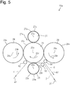
- Embodiment 2 A manufacturing device and a manufacturing method for manufacturing a composite sheet according to Embodiment 2 will be described referring to Figs. 5 and 6 .
- Embodiment 2 is different from Embodiment 1 in that the outer diameters of the second and fourth rollers are different from the outer diameter of the first roller.
- the differences from Embodiment 1 and the same components as those in Embodiment 1 are designated by the same reference numerals and signs.
- Fig. 5 is a schematic view showing a configuration of a composite sheet manufacturing device 10a.
- second to fifth rollers 23, 24, 27 and 28 are disposed in this order so as to be adjacent to the first roller 20.
- the rotation center lines 20x, 23x, 24x, 27x and 28x of the first to fifth rollers 20, 23, 24, 27 and 28 are parallel to one another, and the first to fifth rollers 20, 23, 24, 27 and 28 rotate in the directions indicated by arrows 20r, 23r, 24r, 27r and 28r, respectively, in synchronization with one another.
- the first and second sheets 2 and 4 are fed via the first and second guide rollers 50 and 52 and conveyed through a predetermined path along the outer circumferential face 20s of the first roller 20 in synchronization with the rotation of the first roller 20, and then shaped into a predetermined shape by the first and second projections 23a and 27a protruding from the second and fourth outer circumferential faces 23s, 27s of the second and fourth rollers 23 and 27 and bonded to each other.
- the completed composite sheet 6 is ejected via the third guide roller 54 as indicated by an arrow 6f.
- the outer diameters of the third and fifth rollers are equal to the outer diameter of the first roller 20.
- the outer diameters of the second and fourth rollers 23 and 27 are different from the outer diameter of the first roller 20 and are preferably smaller than the outer diameter of the first roller 20.
- the outer diameters of the second and fourth rollers 23 and 27 are approximately 1/3 of the outer diameter of the first roller 20.
- Fig. 6 is a schematic view showing the drive mechanism 11a of the composite sheet manufacturing device 10a, viewed in parallel to the rotation center lines 20x, 23x, 24x, 27x and 28x (see Fig. 5 ).
- second to fifth gears 33, 34, 37 and 38 are disposed around the first gear 30 so as to be engaged with the first gear 30.
- the mechanism is configured so that the rotations of the first to fifth gears 30, 33, 34, 37 and 38 are transmitted to the first to fifth rollers 20, 23, 24, 27 and 28, respectively.
- the numbers of the teeth of the first, third and fifth gears 30, 34 and 38 are the same.
- the numbers of the teeth of the second and fourth gears 33 and 37 are different from the number of the teeth of the first roller 20 and are preferably less than the number of the teeth of the first gear 30.
- timing belts or the like may be used instead of the second and fourth gears 33 and 37. Furthermore, the second and fourth rollers 23 and 27 and the first, third and fifth rollers 20, 24 and 28 may be driven separately.
- Th composite sheet 6 can be manufactured by performing the above-mentioned steps (1) to (6).
- the first, third and fifth rollers 20, 24 and 28 being equal in outer diameter are rotated at the same rotation frequency via the first, third and fifth gears 30, 34 and 38.
- the composite sheet 6 can be manufactured easily at higher speed and the composite sheet 6 having stable quality can be maintained even when the composite sheet 6 is manufactured at higher speed by using the composite sheet manufacturing device 10a.
- the sheets 2 and 4 are held between the first roller 20 and each of the third roller 23 and the fifth roller 28; however, since the projections 23a and 27a of the second and fourth rollers 23 and 27 are inserted into and extracted from the recessed areas 20a of the first roller 20 in a state in which a clearance is provided between each projection thereof and each recessed area 20a of the first roller 20; hence, the upper limit rotation frequency of the third and fifth rollers 24 and 28 is lower than the upper limit rotation frequency of the second and fourth rollers 23 and 27.
- the rotation frequency of the first roller can be made higher than that in the conventional configuration by simply making the rotation frequency of the third and fifth rollers 24 and 28 equal to the rotation frequency of the first roller 20.
- the composite sheet 6 is manufactured easily at higher speed.
- the composite sheet manufacturing device 10a can be made smaller than the composite sheet manufacturing device 10 according to Embodiment 1 in size.
- the relative rotation error between the first roller 20 and the other rollers 23, 24, 27 and 28 becomes larger, the quality of the composite sheet 6 will be degraded, for example, due to the displacement of shaping and bonding positions.
- the first roller 20 and the other rollers 23, 24, 27 and 28 are rotated and driven separately and controlled so as to be synchronized mutually, if the rotation frequency is made higher, the relative rotation error between the first roller 20 and the other rollers 23, 24, 27 and 28 becomes larger, for example, due to delay in control, whereby it becomes difficult to maintain the quality of the composite sheet 6.
- first roller 20 and the third and fifth rollers 24 and 28 that hold the first and second sheets 2 and 4 therebetween so as to bond the sheets are equal in outer diameter, rotate at the same rotation frequency, and are always opposed mutually at the same portions, the rollers fit easily. Hence, the satisfactory bonding state between the first sheet 2 and the second sheet 4 can be maintained.
- first, third and fifth rollers 20, 24 and 28 are equal in outer diameter and since the first roller 20 is opposed mutually to the third and fifth rollers 24 and 28 at the same portions at all times, readjustment at the time of component exchange is made easy, and assembling accuracy is maintained easily. As a result, the quality of the manufactured composite sheet 6 can be maintained constant.
- Modification 2 is configured such that the fourth roller 27 and the fifth roller 28 in the configuration of Embodiment 2 are eliminated.
- the second roller 23 and the third roller 24 may merely be disposed at appropriate angles around the first roller 20.
- the composite sheet can be manufactured easily at higher speed, and even when the composite sheet is manufactured at higher speed, the composite sheet having stable quality can be manufactured.
- the composite sheet manufacturing device and manufacturing method described above the composite sheet can be manufactured easily at higher speed, and even when the composite sheet is manufactured at higher speed, the composite sheet having stable quality can be manufactured.
- the present invention is not limited to the above-mentioned embodiments and can be modified variously and embodied.
Landscapes
- Health & Medical Sciences (AREA)
- Engineering & Computer Science (AREA)
- Mechanical Engineering (AREA)
- Life Sciences & Earth Sciences (AREA)
- General Health & Medical Sciences (AREA)
- Biomedical Technology (AREA)
- Heart & Thoracic Surgery (AREA)
- Vascular Medicine (AREA)
- Veterinary Medicine (AREA)
- Animal Behavior & Ethology (AREA)
- Epidemiology (AREA)
- Public Health (AREA)
- Manufacturing & Machinery (AREA)
- Textile Engineering (AREA)
- Lining Or Joining Of Plastics Or The Like (AREA)
- Laminated Bodies (AREA)
- Absorbent Articles And Supports Therefor (AREA)
- Shaping Of Tube Ends By Bending Or Straightening (AREA)
Applications Claiming Priority (2)
| Application Number | Priority Date | Filing Date | Title |
|---|---|---|---|
| JP2017195674 | 2017-10-06 | ||
| PCT/JP2018/035514 WO2019069751A1 (ja) | 2017-10-06 | 2018-09-25 | 複合シートの製造装置及び製造方法 |
Publications (3)
| Publication Number | Publication Date |
|---|---|
| EP3666499A1 true EP3666499A1 (de) | 2020-06-17 |
| EP3666499A4 EP3666499A4 (de) | 2021-05-26 |
| EP3666499B1 EP3666499B1 (de) | 2022-02-23 |
Family
ID=65994302
Family Applications (1)
| Application Number | Title | Priority Date | Filing Date |
|---|---|---|---|
| EP18863864.7A Not-in-force EP3666499B1 (de) | 2017-10-06 | 2018-09-25 | Vorrichtung und verfahren zur herstellung von verbundfolien |
Country Status (7)
| Country | Link |
|---|---|
| US (1) | US11865746B2 (de) |
| EP (1) | EP3666499B1 (de) |
| JP (1) | JP7057788B2 (de) |
| KR (1) | KR102255637B1 (de) |
| CN (1) | CN111201123B (de) |
| BR (1) | BR112020006876B1 (de) |
| WO (1) | WO2019069751A1 (de) |
Family Cites Families (15)
| Publication number | Priority date | Publication date | Assignee | Title |
|---|---|---|---|---|
| US4280978A (en) * | 1979-05-23 | 1981-07-28 | Monsanto Company | Process of embossing and perforating thermoplastic film |
| JPH0834336B2 (ja) * | 1990-01-31 | 1996-03-29 | シャープ株式会社 | 半導体レーザ素子及びその製造方法 |
| JP4359357B2 (ja) * | 1999-03-09 | 2009-11-04 | 株式会社瑞光 | ヒートシール装置 |
| JP3984500B2 (ja) * | 2002-05-02 | 2007-10-03 | セーレン株式会社 | 透湿防水性シートの製造方法及びその透湿防水性シート |
| JP4090420B2 (ja) | 2002-11-13 | 2008-05-28 | 花王株式会社 | 吸収性物品用の表面シート |
| US7468114B2 (en) * | 2002-11-13 | 2008-12-23 | Kao Corporation | Composite sheet and process and apparatus for producing the same |
| JP4046677B2 (ja) | 2003-10-10 | 2008-02-13 | 花王株式会社 | 複合シートの製造装置 |
| JP2006017568A (ja) * | 2004-07-01 | 2006-01-19 | Ricoh Elemex Corp | 超音波流量計および受信回路 |
| JP4368297B2 (ja) * | 2004-12-22 | 2009-11-18 | 花王株式会社 | 立体シート |
| US7323072B2 (en) * | 2005-04-27 | 2008-01-29 | Kimberly-Clark Worldwide, Inc. | Multi-roll bonding and aperturing |
| EP1905065B1 (de) * | 2005-06-20 | 2014-08-13 | Microcontinuum, Inc. | Mustererstellung von rolle zu rolle |
| WO2013105330A1 (ja) * | 2012-01-11 | 2013-07-18 | 株式会社瑞光 | シート材賦形装置 |
| MY173787A (en) | 2012-11-30 | 2020-02-21 | Zuiko Corp | Composite sheet material, disposable wearing article using the same, and production method and production apparatus for composite sheet material |
| US10111784B2 (en) * | 2013-09-30 | 2018-10-30 | Zuiko Corporation | Device for producing disposable wearable article and method for producing disposable wearable article |
| CN107735061B (zh) | 2015-06-08 | 2021-04-30 | 株式会社瑞光 | 一种复合片材及其生产制造复合片材的装置和方法 |
-
2018
- 2018-09-25 EP EP18863864.7A patent/EP3666499B1/de not_active Not-in-force
- 2018-09-25 KR KR1020207011665A patent/KR102255637B1/ko not_active Expired - Fee Related
- 2018-09-25 CN CN201880064764.3A patent/CN111201123B/zh active Active
- 2018-09-25 US US16/649,822 patent/US11865746B2/en active Active
- 2018-09-25 JP JP2019546645A patent/JP7057788B2/ja not_active Expired - Fee Related
- 2018-09-25 BR BR112020006876-4A patent/BR112020006876B1/pt not_active IP Right Cessation
- 2018-09-25 WO PCT/JP2018/035514 patent/WO2019069751A1/ja not_active Ceased
Also Published As
| Publication number | Publication date |
|---|---|
| CN111201123A (zh) | 2020-05-26 |
| BR112020006876B1 (pt) | 2023-03-14 |
| EP3666499A4 (de) | 2021-05-26 |
| KR102255637B1 (ko) | 2021-05-24 |
| JP7057788B2 (ja) | 2022-04-20 |
| US11865746B2 (en) | 2024-01-09 |
| KR20200051819A (ko) | 2020-05-13 |
| BR112020006876A2 (pt) | 2020-10-06 |
| US20200282608A1 (en) | 2020-09-10 |
| WO2019069751A1 (ja) | 2019-04-11 |
| CN111201123B (zh) | 2021-09-07 |
| JPWO2019069751A1 (ja) | 2020-11-26 |
| EP3666499B1 (de) | 2022-02-23 |
Similar Documents
| Publication | Publication Date | Title |
|---|---|---|
| EP1943994A2 (de) | Verfahren und Apparat, die Servomotoren benutzen, um Teile auf einem sich bewegenden Gewebe zu plazieren | |
| CN101663007A (zh) | 加工装置 | |
| CN111587100B (zh) | 一次性穿着物品的制造方法及制造装置 | |
| EP3666499B1 (de) | Vorrichtung und verfahren zur herstellung von verbundfolien | |
| JPH09322909A (ja) | サニタリー製品の多列式製造設備 | |
| JP5065882B2 (ja) | 複合シートの製造方法及び装置 | |
| JP6034919B2 (ja) | シート材賦形装置 | |
| EP1303240B1 (de) | Verfahren und apparat, welcher servomotoren benutzt, um teile auf einem sich bewegenden gewebe zu plazieren | |
| EP3272321B1 (de) | Transporteinheit und verfahren zur herstellung von einwegverschleissartikeln damit | |
| CN111491782A (zh) | 片熔接体的制造装置、片熔接体的制造方法和抑制树脂烟尘堆积的方法 | |
| JP5426103B2 (ja) | 複合シートの製造方法及び装置 | |
| JP2021134045A (ja) | 伸縮シートの製造方法および装置 | |
| JP2002035027A (ja) | 着用物品の製造設備 | |
| CN113195179B (zh) | 有关吸收性物品的连续片的复合体的制造方法以及制造装置 | |
| JPH0332820A (ja) | シート加工装置 | |
| JP2004016611A (ja) | 吸収性物品の製造方法及び製造装置 | |
| JP2007099477A (ja) | 伸縮性部材の加工方法 | |
| JP2012091918A (ja) | シートの搬送装置及び搬送方法 | |
| WO2025158952A1 (ja) | 積層体製造装置 | |
| JP2007302983A (ja) | 材料圧縮加工装置 | |
| JPH0494371A (ja) | シート処理機の動力伝達装置 | |
| JP2021020708A (ja) | シール装置、包装装置及びアンビル | |
| JPH0311258B2 (de) | ||
| HK1008973B (en) | Multi-row production equipment of sanitary products |
Legal Events
| Date | Code | Title | Description |
|---|---|---|---|
| STAA | Information on the status of an ep patent application or granted ep patent |
Free format text: STATUS: THE INTERNATIONAL PUBLICATION HAS BEEN MADE |
|
| PUAI | Public reference made under article 153(3) epc to a published international application that has entered the european phase |
Free format text: ORIGINAL CODE: 0009012 |
|
| STAA | Information on the status of an ep patent application or granted ep patent |
Free format text: STATUS: REQUEST FOR EXAMINATION WAS MADE |
|
| 17P | Request for examination filed |
Effective date: 20200309 |
|
| AK | Designated contracting states |
Kind code of ref document: A1 Designated state(s): AL AT BE BG CH CY CZ DE DK EE ES FI FR GB GR HR HU IE IS IT LI LT LU LV MC MK MT NL NO PL PT RO RS SE SI SK SM TR |
|
| AX | Request for extension of the european patent |
Extension state: BA ME |
|
| DAV | Request for validation of the european patent (deleted) | ||
| DAX | Request for extension of the european patent (deleted) | ||
| A4 | Supplementary search report drawn up and despatched |
Effective date: 20210429 |
|
| RIC1 | Information provided on ipc code assigned before grant |
Ipc: B29C 59/04 20060101ALN20210422BHEP Ipc: B32B 38/06 20060101ALI20210422BHEP Ipc: A61F 13/511 20060101ALI20210422BHEP Ipc: A61F 13/15 20060101AFI20210422BHEP |
|
| REG | Reference to a national code |
Ref country code: DE Ref legal event code: R079 Ref document number: 602018031408 Country of ref document: DE Free format text: PREVIOUS MAIN CLASS: B29C0059040000 Ipc: A61F0013150000 |
|
| RIC1 | Information provided on ipc code assigned before grant |
Ipc: B29C 59/04 20060101ALN20210823BHEP Ipc: B32B 38/06 20060101ALI20210823BHEP Ipc: A61F 13/511 20060101ALI20210823BHEP Ipc: A61F 13/15 20060101AFI20210823BHEP |
|
| GRAP | Despatch of communication of intention to grant a patent |
Free format text: ORIGINAL CODE: EPIDOSNIGR1 |
|
| STAA | Information on the status of an ep patent application or granted ep patent |
Free format text: STATUS: GRANT OF PATENT IS INTENDED |
|
| INTG | Intention to grant announced |
Effective date: 20211008 |
|
| GRAS | Grant fee paid |
Free format text: ORIGINAL CODE: EPIDOSNIGR3 |
|
| GRAA | (expected) grant |
Free format text: ORIGINAL CODE: 0009210 |
|
| STAA | Information on the status of an ep patent application or granted ep patent |
Free format text: STATUS: THE PATENT HAS BEEN GRANTED |
|
| AK | Designated contracting states |
Kind code of ref document: B1 Designated state(s): AL AT BE BG CH CY CZ DE DK EE ES FI FR GB GR HR HU IE IS IT LI LT LU LV MC MK MT NL NO PL PT RO RS SE SI SK SM TR |
|
| REG | Reference to a national code |
Ref country code: GB Ref legal event code: FG4D |
|
| REG | Reference to a national code |
Ref country code: CH Ref legal event code: EP |
|
| REG | Reference to a national code |
Ref country code: AT Ref legal event code: REF Ref document number: 1469876 Country of ref document: AT Kind code of ref document: T Effective date: 20220315 |
|
| REG | Reference to a national code |
Ref country code: IE Ref legal event code: FG4D |
|
| REG | Reference to a national code |
Ref country code: DE Ref legal event code: R096 Ref document number: 602018031408 Country of ref document: DE |
|
| REG | Reference to a national code |
Ref country code: LT Ref legal event code: MG9D |
|
| REG | Reference to a national code |
Ref country code: NL Ref legal event code: MP Effective date: 20220223 |
|
| REG | Reference to a national code |
Ref country code: AT Ref legal event code: MK05 Ref document number: 1469876 Country of ref document: AT Kind code of ref document: T Effective date: 20220223 |
|
| PG25 | Lapsed in a contracting state [announced via postgrant information from national office to epo] |
Ref country code: SE Free format text: LAPSE BECAUSE OF FAILURE TO SUBMIT A TRANSLATION OF THE DESCRIPTION OR TO PAY THE FEE WITHIN THE PRESCRIBED TIME-LIMIT Effective date: 20220223 Ref country code: RS Free format text: LAPSE BECAUSE OF FAILURE TO SUBMIT A TRANSLATION OF THE DESCRIPTION OR TO PAY THE FEE WITHIN THE PRESCRIBED TIME-LIMIT Effective date: 20220223 Ref country code: PT Free format text: LAPSE BECAUSE OF FAILURE TO SUBMIT A TRANSLATION OF THE DESCRIPTION OR TO PAY THE FEE WITHIN THE PRESCRIBED TIME-LIMIT Effective date: 20220623 Ref country code: NO Free format text: LAPSE BECAUSE OF FAILURE TO SUBMIT A TRANSLATION OF THE DESCRIPTION OR TO PAY THE FEE WITHIN THE PRESCRIBED TIME-LIMIT Effective date: 20220523 Ref country code: NL Free format text: LAPSE BECAUSE OF FAILURE TO SUBMIT A TRANSLATION OF THE DESCRIPTION OR TO PAY THE FEE WITHIN THE PRESCRIBED TIME-LIMIT Effective date: 20220223 Ref country code: LT Free format text: LAPSE BECAUSE OF FAILURE TO SUBMIT A TRANSLATION OF THE DESCRIPTION OR TO PAY THE FEE WITHIN THE PRESCRIBED TIME-LIMIT Effective date: 20220223 Ref country code: HR Free format text: LAPSE BECAUSE OF FAILURE TO SUBMIT A TRANSLATION OF THE DESCRIPTION OR TO PAY THE FEE WITHIN THE PRESCRIBED TIME-LIMIT Effective date: 20220223 Ref country code: ES Free format text: LAPSE BECAUSE OF FAILURE TO SUBMIT A TRANSLATION OF THE DESCRIPTION OR TO PAY THE FEE WITHIN THE PRESCRIBED TIME-LIMIT Effective date: 20220223 Ref country code: BG Free format text: LAPSE BECAUSE OF FAILURE TO SUBMIT A TRANSLATION OF THE DESCRIPTION OR TO PAY THE FEE WITHIN THE PRESCRIBED TIME-LIMIT Effective date: 20220523 |
|
| PG25 | Lapsed in a contracting state [announced via postgrant information from national office to epo] |
Ref country code: PL Free format text: LAPSE BECAUSE OF FAILURE TO SUBMIT A TRANSLATION OF THE DESCRIPTION OR TO PAY THE FEE WITHIN THE PRESCRIBED TIME-LIMIT Effective date: 20220223 Ref country code: LV Free format text: LAPSE BECAUSE OF FAILURE TO SUBMIT A TRANSLATION OF THE DESCRIPTION OR TO PAY THE FEE WITHIN THE PRESCRIBED TIME-LIMIT Effective date: 20220223 Ref country code: GR Free format text: LAPSE BECAUSE OF FAILURE TO SUBMIT A TRANSLATION OF THE DESCRIPTION OR TO PAY THE FEE WITHIN THE PRESCRIBED TIME-LIMIT Effective date: 20220524 Ref country code: FI Free format text: LAPSE BECAUSE OF FAILURE TO SUBMIT A TRANSLATION OF THE DESCRIPTION OR TO PAY THE FEE WITHIN THE PRESCRIBED TIME-LIMIT Effective date: 20220223 Ref country code: AT Free format text: LAPSE BECAUSE OF FAILURE TO SUBMIT A TRANSLATION OF THE DESCRIPTION OR TO PAY THE FEE WITHIN THE PRESCRIBED TIME-LIMIT Effective date: 20220223 |
|
| PG25 | Lapsed in a contracting state [announced via postgrant information from national office to epo] |
Ref country code: IS Free format text: LAPSE BECAUSE OF FAILURE TO SUBMIT A TRANSLATION OF THE DESCRIPTION OR TO PAY THE FEE WITHIN THE PRESCRIBED TIME-LIMIT Effective date: 20220623 |
|
| PG25 | Lapsed in a contracting state [announced via postgrant information from national office to epo] |
Ref country code: SM Free format text: LAPSE BECAUSE OF FAILURE TO SUBMIT A TRANSLATION OF THE DESCRIPTION OR TO PAY THE FEE WITHIN THE PRESCRIBED TIME-LIMIT Effective date: 20220223 Ref country code: SK Free format text: LAPSE BECAUSE OF FAILURE TO SUBMIT A TRANSLATION OF THE DESCRIPTION OR TO PAY THE FEE WITHIN THE PRESCRIBED TIME-LIMIT Effective date: 20220223 Ref country code: RO Free format text: LAPSE BECAUSE OF FAILURE TO SUBMIT A TRANSLATION OF THE DESCRIPTION OR TO PAY THE FEE WITHIN THE PRESCRIBED TIME-LIMIT Effective date: 20220223 Ref country code: EE Free format text: LAPSE BECAUSE OF FAILURE TO SUBMIT A TRANSLATION OF THE DESCRIPTION OR TO PAY THE FEE WITHIN THE PRESCRIBED TIME-LIMIT Effective date: 20220223 Ref country code: DK Free format text: LAPSE BECAUSE OF FAILURE TO SUBMIT A TRANSLATION OF THE DESCRIPTION OR TO PAY THE FEE WITHIN THE PRESCRIBED TIME-LIMIT Effective date: 20220223 Ref country code: CZ Free format text: LAPSE BECAUSE OF FAILURE TO SUBMIT A TRANSLATION OF THE DESCRIPTION OR TO PAY THE FEE WITHIN THE PRESCRIBED TIME-LIMIT Effective date: 20220223 |
|
| REG | Reference to a national code |
Ref country code: DE Ref legal event code: R097 Ref document number: 602018031408 Country of ref document: DE |
|
| PG25 | Lapsed in a contracting state [announced via postgrant information from national office to epo] |
Ref country code: AL Free format text: LAPSE BECAUSE OF FAILURE TO SUBMIT A TRANSLATION OF THE DESCRIPTION OR TO PAY THE FEE WITHIN THE PRESCRIBED TIME-LIMIT Effective date: 20220223 |
|
| PLBE | No opposition filed within time limit |
Free format text: ORIGINAL CODE: 0009261 |
|
| STAA | Information on the status of an ep patent application or granted ep patent |
Free format text: STATUS: NO OPPOSITION FILED WITHIN TIME LIMIT |
|
| 26N | No opposition filed |
Effective date: 20221124 |
|
| PG25 | Lapsed in a contracting state [announced via postgrant information from national office to epo] |
Ref country code: SI Free format text: LAPSE BECAUSE OF FAILURE TO SUBMIT A TRANSLATION OF THE DESCRIPTION OR TO PAY THE FEE WITHIN THE PRESCRIBED TIME-LIMIT Effective date: 20220223 |
|
| PG25 | Lapsed in a contracting state [announced via postgrant information from national office to epo] |
Ref country code: MC Free format text: LAPSE BECAUSE OF FAILURE TO SUBMIT A TRANSLATION OF THE DESCRIPTION OR TO PAY THE FEE WITHIN THE PRESCRIBED TIME-LIMIT Effective date: 20220223 |
|
| REG | Reference to a national code |
Ref country code: CH Ref legal event code: PL |
|
| GBPC | Gb: european patent ceased through non-payment of renewal fee |
Effective date: 20220925 |
|
| REG | Reference to a national code |
Ref country code: BE Ref legal event code: MM Effective date: 20220930 |
|
| PG25 | Lapsed in a contracting state [announced via postgrant information from national office to epo] |
Ref country code: LU Free format text: LAPSE BECAUSE OF NON-PAYMENT OF DUE FEES Effective date: 20220925 |
|
| P01 | Opt-out of the competence of the unified patent court (upc) registered |
Effective date: 20230621 |
|
| PG25 | Lapsed in a contracting state [announced via postgrant information from national office to epo] |
Ref country code: LI Free format text: LAPSE BECAUSE OF NON-PAYMENT OF DUE FEES Effective date: 20220930 Ref country code: IT Free format text: LAPSE BECAUSE OF FAILURE TO SUBMIT A TRANSLATION OF THE DESCRIPTION OR TO PAY THE FEE WITHIN THE PRESCRIBED TIME-LIMIT Effective date: 20220223 Ref country code: IE Free format text: LAPSE BECAUSE OF NON-PAYMENT OF DUE FEES Effective date: 20220925 Ref country code: FR Free format text: LAPSE BECAUSE OF NON-PAYMENT OF DUE FEES Effective date: 20220930 Ref country code: CH Free format text: LAPSE BECAUSE OF NON-PAYMENT OF DUE FEES Effective date: 20220930 |
|
| PG25 | Lapsed in a contracting state [announced via postgrant information from national office to epo] |
Ref country code: BE Free format text: LAPSE BECAUSE OF NON-PAYMENT OF DUE FEES Effective date: 20220930 |
|
| PG25 | Lapsed in a contracting state [announced via postgrant information from national office to epo] |
Ref country code: GB Free format text: LAPSE BECAUSE OF NON-PAYMENT OF DUE FEES Effective date: 20220925 |
|
| PGFP | Annual fee paid to national office [announced via postgrant information from national office to epo] |
Ref country code: DE Payment date: 20230920 Year of fee payment: 6 |
|
| PG25 | Lapsed in a contracting state [announced via postgrant information from national office to epo] |
Ref country code: CY Free format text: LAPSE BECAUSE OF FAILURE TO SUBMIT A TRANSLATION OF THE DESCRIPTION OR TO PAY THE FEE WITHIN THE PRESCRIBED TIME-LIMIT Effective date: 20220223 |
|
| PG25 | Lapsed in a contracting state [announced via postgrant information from national office to epo] |
Ref country code: MK Free format text: LAPSE BECAUSE OF FAILURE TO SUBMIT A TRANSLATION OF THE DESCRIPTION OR TO PAY THE FEE WITHIN THE PRESCRIBED TIME-LIMIT Effective date: 20220223 Ref country code: HU Free format text: LAPSE BECAUSE OF FAILURE TO SUBMIT A TRANSLATION OF THE DESCRIPTION OR TO PAY THE FEE WITHIN THE PRESCRIBED TIME-LIMIT; INVALID AB INITIO Effective date: 20180925 |
|
| PG25 | Lapsed in a contracting state [announced via postgrant information from national office to epo] |
Ref country code: TR Free format text: LAPSE BECAUSE OF FAILURE TO SUBMIT A TRANSLATION OF THE DESCRIPTION OR TO PAY THE FEE WITHIN THE PRESCRIBED TIME-LIMIT Effective date: 20220223 |
|
| PG25 | Lapsed in a contracting state [announced via postgrant information from national office to epo] |
Ref country code: MT Free format text: LAPSE BECAUSE OF FAILURE TO SUBMIT A TRANSLATION OF THE DESCRIPTION OR TO PAY THE FEE WITHIN THE PRESCRIBED TIME-LIMIT Effective date: 20220223 |
|
| REG | Reference to a national code |
Ref country code: DE Ref legal event code: R119 Ref document number: 602018031408 Country of ref document: DE |
|
| PG25 | Lapsed in a contracting state [announced via postgrant information from national office to epo] |
Ref country code: DE Free format text: LAPSE BECAUSE OF NON-PAYMENT OF DUE FEES Effective date: 20250401 |