EP3666444B1 - Verfahren zur herstellung eines mehrschichtigen elements für luft- und raumfahrtanwendungen - Google Patents
Verfahren zur herstellung eines mehrschichtigen elements für luft- und raumfahrtanwendungen Download PDFInfo
- Publication number
- EP3666444B1 EP3666444B1 EP19215404.5A EP19215404A EP3666444B1 EP 3666444 B1 EP3666444 B1 EP 3666444B1 EP 19215404 A EP19215404 A EP 19215404A EP 3666444 B1 EP3666444 B1 EP 3666444B1
- Authority
- EP
- European Patent Office
- Prior art keywords
- sheets
- sheet
- stack
- straps
- multilayer member
- Prior art date
- Legal status (The legal status is an assumption and is not a legal conclusion. Google has not performed a legal analysis and makes no representation as to the accuracy of the status listed.)
- Active
Links
Images

Classifications
-
- B—PERFORMING OPERATIONS; TRANSPORTING
- B23—MACHINE TOOLS; METAL-WORKING NOT OTHERWISE PROVIDED FOR
- B23K—SOLDERING OR UNSOLDERING; WELDING; CLADDING OR PLATING BY SOLDERING OR WELDING; CUTTING BY APPLYING HEAT LOCALLY, e.g. FLAME CUTTING; WORKING BY LASER BEAM
- B23K20/00—Non-electric welding by applying impact or other pressure, with or without the application of heat, e.g. cladding or plating
- B23K20/12—Non-electric welding by applying impact or other pressure, with or without the application of heat, e.g. cladding or plating the heat being generated by friction; Friction welding
- B23K20/122—Non-electric welding by applying impact or other pressure, with or without the application of heat, e.g. cladding or plating the heat being generated by friction; Friction welding using a non-consumable tool, e.g. friction stir welding
-
- B—PERFORMING OPERATIONS; TRANSPORTING
- B64—AIRCRAFT; AVIATION; COSMONAUTICS
- B64G—COSMONAUTICS; VEHICLES OR EQUIPMENT THEREFOR
- B64G1/00—Cosmonautic vehicles
- B64G1/22—Parts of, or equipment specially adapted for fitting in or to, cosmonautic vehicles
- B64G1/46—Arrangements or adaptations of devices for control of environment or living conditions
- B64G1/50—Arrangements or adaptations of devices for control of environment or living conditions for temperature control
-
- H—ELECTRICITY
- H05—ELECTRIC TECHNIQUES NOT OTHERWISE PROVIDED FOR
- H05K—PRINTED CIRCUITS; CASINGS OR CONSTRUCTIONAL DETAILS OF ELECTRIC APPARATUS; MANUFACTURE OF ASSEMBLAGES OF ELECTRICAL COMPONENTS
- H05K7/00—Constructional details common to different types of electric apparatus
- H05K7/20—Modifications to facilitate cooling, ventilating, or heating
- H05K7/2039—Modifications to facilitate cooling, ventilating, or heating characterised by the heat transfer by conduction from the heat generating element to a dissipating body
-
- H—ELECTRICITY
- H10—SEMICONDUCTOR DEVICES; ELECTRIC SOLID-STATE DEVICES NOT OTHERWISE PROVIDED FOR
- H10W—GENERIC PACKAGES, INTERCONNECTIONS, CONNECTORS OR OTHER CONSTRUCTIONAL DETAILS OF DEVICES COVERED BY CLASS H10
- H10W40/00—Arrangements for thermal protection or thermal control
- H10W40/10—Arrangements for heating
-
- H—ELECTRICITY
- H10—SEMICONDUCTOR DEVICES; ELECTRIC SOLID-STATE DEVICES NOT OTHERWISE PROVIDED FOR
- H10W—GENERIC PACKAGES, INTERCONNECTIONS, CONNECTORS OR OTHER CONSTRUCTIONAL DETAILS OF DEVICES COVERED BY CLASS H10
- H10W40/00—Arrangements for thermal protection or thermal control
- H10W40/20—Arrangements for cooling
- H10W40/25—Arrangements for cooling characterised by their materials
-
- H—ELECTRICITY
- H10—SEMICONDUCTOR DEVICES; ELECTRIC SOLID-STATE DEVICES NOT OTHERWISE PROVIDED FOR
- H10W—GENERIC PACKAGES, INTERCONNECTIONS, CONNECTORS OR OTHER CONSTRUCTIONAL DETAILS OF DEVICES COVERED BY CLASS H10
- H10W70/00—Package substrates; Interposers; Redistribution layers [RDL]
- H10W70/01—Manufacture or treatment
- H10W70/02—Manufacture or treatment of conductive package substrates serving as an interconnection, e.g. of metal plates
Definitions
- the present invention relates to a method of manufacturing a multilayer member for aeronautic and aerospace applications.
- Multilayer members for aeronautic and aerospace applications comprise thermal straps.
- the thermal straps used in the aeronautical and aerospace fields are generally of two types.
- the thermal strap comprises a stack of thermally conductive sheets made of a metallic material such as, for example, aluminium or copper or alloys thereof or of a non-metallic material such as, for example, graphite or graphene or carbon fibres.
- the sheets have, for example, an elongated rectangular shape, and comprise a flexible central portion and two mechanical coupling interfaces on opposite sides of the central portion to enable the thermal strap to be connected to the two objects.
- the sheets are mutually separated at the central portion, and are mutually connected, for example through pressing, at the mechanical coupling interfaces.
- each mechanical coupling interface is connected to the corresponding object through at least one screw or clamping bolt mounted through the sheets.
- the thermal strap comprises at least one braid or strand comprising, in turn, a plurality of thermally conductive wires made of a metallic material such as, for example, aluminium or copper or alloys thereof or of a non-metallic material such as, for example, graphite or graphene or carbon fibres.
- the braid or strand comprises a flexible central portion and two mechanical coupling interfaces on opposite sides of the central portion to enable the thermal strap to be connected to the two objects.
- the wires are mutually separated at the central portion, and are mutually connected, for example through pressing, at the mechanical coupling interfaces.
- each mechanical coupling interface is connected to the corresponding object through at least one screw or clamping bolt mounted through the wires.
- WO2018219515 A1 discloses flexible connector comprising a multilayer metal strip and at least one connecting element arranged at at least one strip end, wherein the layers of the metal strip are joined together in the region of the strip end by friction welding, and a reinforcement element (6) is arranged at the strip end (2) and is bonded to the strip.
- US 2016/128227 A1 discloses a heat transfer system comprising a heat source, a first heat exchanger coupled to the heat source to remove heat from the heat source, and a second heat exchanger, which is coupled to the first heat exchanger to remove heat from the first heat exchanger.
- the heat transfer system also comprises, furthermore, a heat duplicator coupled to the second heat exchanger to remove heat from the second heat exchanger, a first heat pipe coupled to the heat duplicator to remove heat from the heat duplicator, and a second heat pipe, which is coupled to the first heat pipe to remove heat from the first heat pipe.
- US 2017/216958 A1 discloses a method of diffusion bonding and forming metallic sheets.
- the method comprises stacking a first metallic sheet and a second metallic sheet to define a sheet slack; creating a pneumatic seal between the first metallic sheet and the second metallic sheet to define a sealed sheet stack that defines a pneumatically isolated region; increasing a surface area of the sealed sheet stack to define an expanded sheet stack; and compressing at least a portion of the expanded sheet stack to form a diffusion bond between a corresponding portion of the first metallic sheet and an opposed portion of the second metallic sheet, thereby defining a diffusion bonded sheet stack.
- Thermal conductance characterization of a pressed copper rope strap between 0.13 K and 10 K relates to a method of mechanical pressing the ends of a solid copper braid to build seamless conductive belts for cryogenic applications.
- thermal straps of the above-described type have some drawbacks mainly due to the fact that, at the mechanical coupling interfaces, each pair of adjacent sheets or wires exposes a discontinuity of material, which leads to additional thermal resistance, and limits the correct and homogeneous transmission of heat along the thermal strap.
- thermal straps of the above-described type also have the additional drawback that the costs and time for their procurement are relatively high.
- the aim of the present invention is to provide a method of manufacturing a multilayer member for aeronautic and aerospace applications.
- reference numeral 1 references, as a whole, a thermal strap to mutually connect two objects (not shown), in particular two objects having different temperatures.
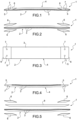
- the thermal strap 1 comprises a stack 2 of thermally conductive sheets 3.
- the stack 2 comprises a number of sheets 3 ranging between 10 to 2000, and each sheet 3 has an elongated rectangular shape and is 0.005 mm to 2 mm thick.
- Sheets 3 are made of a thermally conductive metallic material such as, for example, aluminium or copper or alloys thereof, or of a thermally conductive non-metallic material such as, for example, graphite or graphene or carbon fibres.
- sheets 3 are made of the same material and have the same thickness.
- Thermal strap 1 further defines a flexible central portion 4, where sheets 3 are mutually separated, i.e., they are not mutually connected, and two end portions 5 arranged on opposite sides of the flexible central portion 4.
- sheets 3 are mutually welded and further welded to a pair of thermally conductive straps 6, which are arranged on opposite sides of sheets 3, are made of either the same material as, or a different material from, sheets 3, and each of which is thicker than a sheet 3, in particular a thickness of at least 0.8 mm.
- Sheets 3 and straps 6 are mutually welded through a Friction Stir Welding (FSW) process, namely a solid state friction stir welding and remixing process wherein the material to be welded fails to reach melting temperature and the weld bead is generated by contact between a rotating welding tool, straps 6, and sheets 3.
- the welding tool comprises a shoulder, rotation of which generates friction and, hence, heat, making the material plastic; and a pin, the rotation of which remixes the plasticised material by mutually joining sheets 3 and straps 6.
- Each end portion 5 defines a mechanical connection interface provided with a pair of coupling holes 7, which enable end portion 5 to be connected to the corresponding object (not shown) through respective clamping screws (not shown) or respective clamping bolts (not shown) mounted through coupling holes 7.
- the number of holes 7 in each mechanical connection interface may be different from two.
- each end portion 5 is joined to only one strap 6 arranged on an end face of stack 2 where welding of sheets 3 and of strap 6 is carried out.
- Sheet 8 is made of either the same material as, or a different material from, sheets 3, and is thicker than a sheet 3.
- Sheets 3, straps 6, and sheet 8 are mutually welded at the two end portions 5 through Friction Stir Welding. Sheets 3 and 8 are mutually separated, i.e., they are not mutually connected, at the flexible central portion 4.
- thermal strap 1 comprises two sheets 8 arranged on opposite sides of the stack 2 of sheets 3.
- straps 6 are removed and sheets 3 and 8 are mutually welded at the end portions 5 to define corresponding mechanical connection interfaces, and are mutually separated, i.e., they are not mutually connected, at the flexible central portion 4.
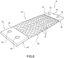
- Figure 6 shows a thermal strap 9 having at least one braid or strand 10 comprising a plurality of thermally conductive wires 11 made of a metallic material such as, for example, aluminium or copper or alloys thereof, or of a non-metallic material such as, for example, graphite or graphene or carbon fibres.
- a metallic material such as, for example, aluminium or copper or alloys thereof
- a non-metallic material such as, for example, graphite or graphene or carbon fibres.
- wires 11 are made of the same material and have the same diameter.
- Thermal strap 9 further comprises a flexible central portion 12, at which wires 11 are mutually separated, i.e., they are not mutually connected, and two end portions 13 arranged on opposite sides of the flexible central portion 12.
- wires 11 are mutually welded and also welded to a pair of thermally conductive straps 14, which are arranged on opposite sides of wires 11, are made either of the same material as, or a different material from, wires 11, and each of which has a given thickness, in particular a thickness of at least 0.8 mm.
- Wires 11 and straps 14 are mutually welded through a Friction Stir Welding process.
- Each end portion 13 defines a mechanical connection interface provided with a pair of coupling holes 15, which enable end portion 13 to be connected to the corresponding object (not shown) through respective clamping screws (not shown) or respective clamping bolts (not shown) mounted through holes 15.
- the number of holes 15 in each mechanical connection interface may be different from two.
- Figures 7 and 8 show a multilayer member 16 for use, for example, as a meteoritic impact protection panel.
- Multilayer member 16 comprises a stack 17 of sheets 18 having, in the example shown, a quadrilateral shape. Obviously, in a variant not shown, sheets 18 may have a different shape from quadrilateral.
- Stack 17 comprises a number of sheets 18 ranging between 10 to 2000 and each sheet 18 is 0.005 mm to 2 mm thick, and is made of either a metallic material such as, for example, aluminium or aluminium metallic alloys or a non-metallic material such as, for example, a polymeric material.
- a metallic material such as, for example, aluminium or aluminium metallic alloys
- a non-metallic material such as, for example, a polymeric material.
- sheets 18 are made of the same material and have the same thickness.
- Multilayer member 16 further comprises an end sheet 19, which has substantially the same shape as sheets 18, overlaps sheets 18, is made of either the same material as or a different material from, sheets 18, and is thicker than a sheet 18.
- multilayer member 16 comprises two sheets 19 arranged on opposite sides of sheets 18.
- Stack 17 comprises a central portion 20 and a perimetral edge 21 extending around at least part of portion 20.
- Sheets 18 and 19 are mutually separated, i.e., they are not mutually connected, at the central portion 20, and are mutually welded along at least part of perimetral edge 21.
- sheets 18 and 19 are mutually welded at the perimetral edge 21 through a Friction Stir Welding process.
- sheet 19 is replaced with a strap, which is arranged along perimetral edge 21, is made of either the same material as or a different material from, sheets 18, and is thicker than a sheet 18.
- Sheets 18 and strap are mutually welded along perimetral edge 21 through a Friction Stir Welding process and, in order to ensure relatively high flexibility of multilayer member 16, at central portion 20.
Landscapes
- Engineering & Computer Science (AREA)
- Life Sciences & Earth Sciences (AREA)
- Environmental & Geological Engineering (AREA)
- Microelectronics & Electronic Packaging (AREA)
- Mechanical Engineering (AREA)
- Health & Medical Sciences (AREA)
- Physics & Mathematics (AREA)
- Biodiversity & Conservation Biology (AREA)
- Thermal Sciences (AREA)
- Environmental Sciences (AREA)
- General Health & Medical Sciences (AREA)
- Toxicology (AREA)
- Remote Sensing (AREA)
- Aviation & Aerospace Engineering (AREA)
- Pressure Welding/Diffusion-Bonding (AREA)
Claims (2)
- Verfahren zur Herstellung eines mehrschichtigen Elements (16) für Luft- und Raumfahrtanwendungen, das aufweist:- Ausbilden eines Stapels (17) von Lagen (18), wobei der Stapel (17) eine Anzahl von Lagen (18) im Bereich zwischen 10 und 2000 aufweist, und wobei jede Lage (18) 0,005 mm bis 2 mm dick ist; und- wenigstens teilweise wechselseitiges Schweißen der Lagen (18) durch Rührreibschweißen entlang wenigstens eines Teils eines Umfangsrands (21) des Stapels (17) von Lagen (18), um das mehrschichtige Element (16) auszubilden.
- Verfahren nach Anspruch 1, das außerdem die folgenden Schritte aufweist:- Anordnen entweder einer Endlage (19) auf dem Stapel (17) von Lagen (18) oder wenigstens eines Endstreifens entlang wenigstens eines Teils des Umfangsrands (21) des Stapels (17) von Lagen (18); und- Verschweißen entweder der Endlage (19) oder des Endstreifens entlang wenigstens eines Teils des Umfangsrands (21) mit den anderen Lagen (18), um das mehrschichtige Element (16) auszubilden;wobei die Endlage (19) oder der Endstreifen aus dem gleichen Material oder einem dazu verschiedenen Material wie die anderen Lagen (18) und/oder mit einer größeren Dicke als die anderen Lagen (18) hergestellt ist.
Applications Claiming Priority (1)
| Application Number | Priority Date | Filing Date | Title |
|---|---|---|---|
| IT201800010987 | 2018-12-11 |
Publications (2)
| Publication Number | Publication Date |
|---|---|
| EP3666444A1 EP3666444A1 (de) | 2020-06-17 |
| EP3666444B1 true EP3666444B1 (de) | 2025-01-29 |
Family
ID=65861566
Family Applications (1)
| Application Number | Title | Priority Date | Filing Date |
|---|---|---|---|
| EP19215404.5A Active EP3666444B1 (de) | 2018-12-11 | 2019-12-11 | Verfahren zur herstellung eines mehrschichtigen elements für luft- und raumfahrtanwendungen |
Country Status (2)
| Country | Link |
|---|---|
| EP (1) | EP3666444B1 (de) |
| ES (1) | ES3010406T3 (de) |
Families Citing this family (1)
| Publication number | Priority date | Publication date | Assignee | Title |
|---|---|---|---|---|
| FI20235273A1 (en) * | 2023-03-09 | 2024-09-10 | Teknologian Tutkimuskeskus Vtt Oy | Heat belt and method for making a heat belt |
Citations (1)
| Publication number | Priority date | Publication date | Assignee | Title |
|---|---|---|---|---|
| WO2018219515A1 (de) * | 2017-06-01 | 2018-12-06 | Auto-Kabel Management Gmbh | Verbinder und verfahren zur herstellung eines verbinders |
Family Cites Families (2)
| Publication number | Priority date | Publication date | Assignee | Title |
|---|---|---|---|---|
| US10225953B2 (en) | 2014-10-31 | 2019-03-05 | Thermal Corp. | Vehicle thermal management system |
| US10155281B2 (en) | 2016-01-29 | 2018-12-18 | The Boeing Company | Methods and process flows for diffusion bonding and forming metallic sheets |
-
2019
- 2019-12-11 EP EP19215404.5A patent/EP3666444B1/de active Active
- 2019-12-11 ES ES19215404T patent/ES3010406T3/es active Active
Patent Citations (1)
| Publication number | Priority date | Publication date | Assignee | Title |
|---|---|---|---|---|
| WO2018219515A1 (de) * | 2017-06-01 | 2018-12-06 | Auto-Kabel Management Gmbh | Verbinder und verfahren zur herstellung eines verbinders |
Also Published As
| Publication number | Publication date |
|---|---|
| ES3010406T3 (en) | 2025-04-02 |
| EP3666444A1 (de) | 2020-06-17 |
Similar Documents
| Publication | Publication Date | Title |
|---|---|---|
| Xiong et al. | Resistance welding technology of fiber reinforced polymer composites: a review | |
| KR100570312B1 (ko) | 접합 방법 및 조인트용 밀봉제 | |
| US3072225A (en) | Honeycomb sandwich structure | |
| JP6554263B2 (ja) | 超塑性成形され超音波溶接された金属構造体 | |
| EP3088163B1 (de) | Rührreibschweissen von thermoplasten | |
| US3479730A (en) | Method of and assembly for the joining of elements of different materials | |
| HU218763B (hu) | Eljárás megerősített, hőre lágyuló tagok, főleg csövek összekapcsolására | |
| US9931809B2 (en) | Composite material structure and method of manufacturing composite material structure | |
| US7690164B2 (en) | System, method, and apparatus for structural lug formed from a combination of metal and composite laminate materials | |
| EP1875981A2 (de) | System, Verfahren und Vorrichtung für eine dreidimensionale strukturelle Verbindung einer Metallgewebevorform | |
| JP2020104172A (ja) | バスバー製造方法 | |
| EP3666444A1 (de) | Thermisches band, mehrschichtiges element für luft- und raumfahrtanwendungen sowie verfahren zu dessen herstellung | |
| CN110014660B (zh) | 用于制造载具构件的方法、载具构件及具有载具构件的载具 | |
| US3807044A (en) | Method for making heating mats | |
| JP5189578B2 (ja) | 集束チューブを用いた樹脂製熱交換器 | |
| EP4603260A1 (de) | Verfahren zum verbinden von thermoplastischen verbundkomponenten | |
| WO2018078917A1 (ja) | エスカレータ手摺及びその製造方法 | |
| JP6690619B2 (ja) | 金属樹脂接合体およびその製造方法 | |
| JP3160339B2 (ja) | 壁組立体、およびその製造方法 | |
| TWI645423B (zh) | 分流電阻器之製造方法 | |
| US12005515B2 (en) | Different material joining method | |
| CN122071141A (zh) | 聚合物基复合材料接头、用于处理聚合物基复合材料接头的系统和方法 | |
| EP4501601A1 (de) | Verfahren zur aktiven kühlung und abstützung von bauteilen beim thermoplastischen verbundschweissen | |
| JP6851934B2 (ja) | 筒状ゴムシートの製造方法 | |
| EP4219133A1 (de) | Verfahren zur oberflächenstrukturierung |
Legal Events
| Date | Code | Title | Description |
|---|---|---|---|
| PUAI | Public reference made under article 153(3) epc to a published international application that has entered the european phase |
Free format text: ORIGINAL CODE: 0009012 |
|
| STAA | Information on the status of an ep patent application or granted ep patent |
Free format text: STATUS: THE APPLICATION HAS BEEN PUBLISHED |
|
| AK | Designated contracting states |
Kind code of ref document: A1 Designated state(s): AL AT BE BG CH CY CZ DE DK EE ES FI FR GB GR HR HU IE IS IT LI LT LU LV MC MK MT NL NO PL PT RO RS SE SI SK SM TR |
|
| AX | Request for extension of the european patent |
Extension state: BA ME |
|
| STAA | Information on the status of an ep patent application or granted ep patent |
Free format text: STATUS: REQUEST FOR EXAMINATION WAS MADE |
|
| 17P | Request for examination filed |
Effective date: 20201126 |
|
| RBV | Designated contracting states (corrected) |
Designated state(s): AL AT BE BG CH CY CZ DE DK EE ES FI FR GB GR HR HU IE IS IT LI LT LU LV MC MK MT NL NO PL PT RO RS SE SI SK SM TR |
|
| STAA | Information on the status of an ep patent application or granted ep patent |
Free format text: STATUS: EXAMINATION IS IN PROGRESS |
|
| 17Q | First examination report despatched |
Effective date: 20220725 |
|
| P01 | Opt-out of the competence of the unified patent court (upc) registered |
Effective date: 20230518 |
|
| GRAP | Despatch of communication of intention to grant a patent |
Free format text: ORIGINAL CODE: EPIDOSNIGR1 |
|
| STAA | Information on the status of an ep patent application or granted ep patent |
Free format text: STATUS: GRANT OF PATENT IS INTENDED |
|
| GRAJ | Information related to disapproval of communication of intention to grant by the applicant or resumption of examination proceedings by the epo deleted |
Free format text: ORIGINAL CODE: EPIDOSDIGR1 |
|
| STAA | Information on the status of an ep patent application or granted ep patent |
Free format text: STATUS: EXAMINATION IS IN PROGRESS |
|
| INTG | Intention to grant announced |
Effective date: 20240613 |
|
| INTC | Intention to grant announced (deleted) | ||
| GRAP | Despatch of communication of intention to grant a patent |
Free format text: ORIGINAL CODE: EPIDOSNIGR1 |
|
| STAA | Information on the status of an ep patent application or granted ep patent |
Free format text: STATUS: GRANT OF PATENT IS INTENDED |
|
| INTG | Intention to grant announced |
Effective date: 20240819 |
|
| GRAS | Grant fee paid |
Free format text: ORIGINAL CODE: EPIDOSNIGR3 |
|
| GRAA | (expected) grant |
Free format text: ORIGINAL CODE: 0009210 |
|
| STAA | Information on the status of an ep patent application or granted ep patent |
Free format text: STATUS: THE PATENT HAS BEEN GRANTED |
|
| AK | Designated contracting states |
Kind code of ref document: B1 Designated state(s): AL AT BE BG CH CY CZ DE DK EE ES FI FR GB GR HR HU IE IS IT LI LT LU LV MC MK MT NL NO PL PT RO RS SE SI SK SM TR |
|
| REG | Reference to a national code |
Ref country code: GB Ref legal event code: FG4D |
|
| REG | Reference to a national code |
Ref country code: CH Ref legal event code: EP |
|
| REG | Reference to a national code |
Ref country code: DE Ref legal event code: R096 Ref document number: 602019065350 Country of ref document: DE |
|
| REG | Reference to a national code |
Ref country code: IE Ref legal event code: FG4D |
|
| REG | Reference to a national code |
Ref country code: NL Ref legal event code: FP |
|
| REG | Reference to a national code |
Ref country code: ES Ref legal event code: FG2A Ref document number: 3010406 Country of ref document: ES Kind code of ref document: T3 Effective date: 20250402 |
|
| PG25 | Lapsed in a contracting state [announced via postgrant information from national office to epo] |
Ref country code: RS Free format text: LAPSE BECAUSE OF FAILURE TO SUBMIT A TRANSLATION OF THE DESCRIPTION OR TO PAY THE FEE WITHIN THE PRESCRIBED TIME-LIMIT Effective date: 20250429 |
|
| PG25 | Lapsed in a contracting state [announced via postgrant information from national office to epo] |
Ref country code: FI Free format text: LAPSE BECAUSE OF FAILURE TO SUBMIT A TRANSLATION OF THE DESCRIPTION OR TO PAY THE FEE WITHIN THE PRESCRIBED TIME-LIMIT Effective date: 20250129 |
|
| PG25 | Lapsed in a contracting state [announced via postgrant information from national office to epo] |
Ref country code: PL Free format text: LAPSE BECAUSE OF FAILURE TO SUBMIT A TRANSLATION OF THE DESCRIPTION OR TO PAY THE FEE WITHIN THE PRESCRIBED TIME-LIMIT Effective date: 20250129 |
|
| REG | Reference to a national code |
Ref country code: LT Ref legal event code: MG9D |
|
| PG25 | Lapsed in a contracting state [announced via postgrant information from national office to epo] |
Ref country code: NO Free format text: LAPSE BECAUSE OF FAILURE TO SUBMIT A TRANSLATION OF THE DESCRIPTION OR TO PAY THE FEE WITHIN THE PRESCRIBED TIME-LIMIT Effective date: 20250429 Ref country code: IS Free format text: LAPSE BECAUSE OF FAILURE TO SUBMIT A TRANSLATION OF THE DESCRIPTION OR TO PAY THE FEE WITHIN THE PRESCRIBED TIME-LIMIT Effective date: 20250529 |
|
| REG | Reference to a national code |
Ref country code: AT Ref legal event code: MK05 Ref document number: 1762975 Country of ref document: AT Kind code of ref document: T Effective date: 20250129 |
|
| PG25 | Lapsed in a contracting state [announced via postgrant information from national office to epo] |
Ref country code: HR Free format text: LAPSE BECAUSE OF FAILURE TO SUBMIT A TRANSLATION OF THE DESCRIPTION OR TO PAY THE FEE WITHIN THE PRESCRIBED TIME-LIMIT Effective date: 20250129 |
|
| PG25 | Lapsed in a contracting state [announced via postgrant information from national office to epo] |
Ref country code: PT Free format text: LAPSE BECAUSE OF FAILURE TO SUBMIT A TRANSLATION OF THE DESCRIPTION OR TO PAY THE FEE WITHIN THE PRESCRIBED TIME-LIMIT Effective date: 20250529 Ref country code: LV Free format text: LAPSE BECAUSE OF FAILURE TO SUBMIT A TRANSLATION OF THE DESCRIPTION OR TO PAY THE FEE WITHIN THE PRESCRIBED TIME-LIMIT Effective date: 20250129 |
|
| PG25 | Lapsed in a contracting state [announced via postgrant information from national office to epo] |
Ref country code: GR Free format text: LAPSE BECAUSE OF FAILURE TO SUBMIT A TRANSLATION OF THE DESCRIPTION OR TO PAY THE FEE WITHIN THE PRESCRIBED TIME-LIMIT Effective date: 20250430 Ref country code: BG Free format text: LAPSE BECAUSE OF FAILURE TO SUBMIT A TRANSLATION OF THE DESCRIPTION OR TO PAY THE FEE WITHIN THE PRESCRIBED TIME-LIMIT Effective date: 20250129 |
|
| PG25 | Lapsed in a contracting state [announced via postgrant information from national office to epo] |
Ref country code: AT Free format text: LAPSE BECAUSE OF FAILURE TO SUBMIT A TRANSLATION OF THE DESCRIPTION OR TO PAY THE FEE WITHIN THE PRESCRIBED TIME-LIMIT Effective date: 20250129 |
|
| PG25 | Lapsed in a contracting state [announced via postgrant information from national office to epo] |
Ref country code: SE Free format text: LAPSE BECAUSE OF FAILURE TO SUBMIT A TRANSLATION OF THE DESCRIPTION OR TO PAY THE FEE WITHIN THE PRESCRIBED TIME-LIMIT Effective date: 20250129 |
|
| PG25 | Lapsed in a contracting state [announced via postgrant information from national office to epo] |
Ref country code: SM Free format text: LAPSE BECAUSE OF FAILURE TO SUBMIT A TRANSLATION OF THE DESCRIPTION OR TO PAY THE FEE WITHIN THE PRESCRIBED TIME-LIMIT Effective date: 20250129 |
|
| PG25 | Lapsed in a contracting state [announced via postgrant information from national office to epo] |
Ref country code: DK Free format text: LAPSE BECAUSE OF FAILURE TO SUBMIT A TRANSLATION OF THE DESCRIPTION OR TO PAY THE FEE WITHIN THE PRESCRIBED TIME-LIMIT Effective date: 20250129 |
|
| PG25 | Lapsed in a contracting state [announced via postgrant information from national office to epo] |
Ref country code: CZ Free format text: LAPSE BECAUSE OF FAILURE TO SUBMIT A TRANSLATION OF THE DESCRIPTION OR TO PAY THE FEE WITHIN THE PRESCRIBED TIME-LIMIT Effective date: 20250129 Ref country code: EE Free format text: LAPSE BECAUSE OF FAILURE TO SUBMIT A TRANSLATION OF THE DESCRIPTION OR TO PAY THE FEE WITHIN THE PRESCRIBED TIME-LIMIT Effective date: 20250129 |
|
| PG25 | Lapsed in a contracting state [announced via postgrant information from national office to epo] |
Ref country code: RO Free format text: LAPSE BECAUSE OF FAILURE TO SUBMIT A TRANSLATION OF THE DESCRIPTION OR TO PAY THE FEE WITHIN THE PRESCRIBED TIME-LIMIT Effective date: 20250129 |
|
| PG25 | Lapsed in a contracting state [announced via postgrant information from national office to epo] |
Ref country code: SK Free format text: LAPSE BECAUSE OF FAILURE TO SUBMIT A TRANSLATION OF THE DESCRIPTION OR TO PAY THE FEE WITHIN THE PRESCRIBED TIME-LIMIT Effective date: 20250129 |
|
| REG | Reference to a national code |
Ref country code: DE Ref legal event code: R097 Ref document number: 602019065350 Country of ref document: DE |
|
| PLBE | No opposition filed within time limit |
Free format text: ORIGINAL CODE: 0009261 |
|
| STAA | Information on the status of an ep patent application or granted ep patent |
Free format text: STATUS: NO OPPOSITION FILED WITHIN TIME LIMIT |
|
| REG | Reference to a national code |
Ref country code: CH Ref legal event code: L10 Free format text: ST27 STATUS EVENT CODE: U-0-0-L10-L00 (AS PROVIDED BY THE NATIONAL OFFICE) Effective date: 20251210 |
|
| REG | Reference to a national code |
Ref country code: CH Ref legal event code: U11 Free format text: ST27 STATUS EVENT CODE: U-0-0-U10-U11 (AS PROVIDED BY THE NATIONAL OFFICE) Effective date: 20260101 |
|
| 26N | No opposition filed |
Effective date: 20251030 |
|
| PGFP | Annual fee paid to national office [announced via postgrant information from national office to epo] |
Ref country code: GB Payment date: 20251223 Year of fee payment: 7 |
|
| PGFP | Annual fee paid to national office [announced via postgrant information from national office to epo] |
Ref country code: IT Payment date: 20251117 Year of fee payment: 7 |
|
| PGFP | Annual fee paid to national office [announced via postgrant information from national office to epo] |
Ref country code: NL Payment date: 20251222 Year of fee payment: 7 Ref country code: FR Payment date: 20251223 Year of fee payment: 7 |
|
| PGFP | Annual fee paid to national office [announced via postgrant information from national office to epo] |
Ref country code: ES Payment date: 20260122 Year of fee payment: 7 |
|
| PGFP | Annual fee paid to national office [announced via postgrant information from national office to epo] |
Ref country code: DE Payment date: 20251229 Year of fee payment: 7 |
|
| PGFP | Annual fee paid to national office [announced via postgrant information from national office to epo] |
Ref country code: CH Payment date: 20260101 Year of fee payment: 7 |