EP3665448B1 - Lastbestimmungsvorrichtung und zugehöriges herstellungsverfahren - Google Patents
Lastbestimmungsvorrichtung und zugehöriges herstellungsverfahren Download PDFInfo
- Publication number
- EP3665448B1 EP3665448B1 EP18743541.7A EP18743541A EP3665448B1 EP 3665448 B1 EP3665448 B1 EP 3665448B1 EP 18743541 A EP18743541 A EP 18743541A EP 3665448 B1 EP3665448 B1 EP 3665448B1
- Authority
- EP
- European Patent Office
- Prior art keywords
- component
- load
- determination device
- load determination
- hull
- Prior art date
- Legal status (The legal status is an assumption and is not a legal conclusion. Google has not performed a legal analysis and makes no representation as to the accuracy of the status listed.)
- Active
Links
Images

Classifications
-
- A—HUMAN NECESSITIES
- A61—MEDICAL OR VETERINARY SCIENCE; HYGIENE
- A61J—CONTAINERS SPECIALLY ADAPTED FOR MEDICAL OR PHARMACEUTICAL PURPOSES; DEVICES OR METHODS SPECIALLY ADAPTED FOR BRINGING PHARMACEUTICAL PRODUCTS INTO PARTICULAR PHYSICAL OR ADMINISTERING FORMS; DEVICES FOR ADMINISTERING FOOD OR MEDICINES ORALLY; BABY COMFORTERS; DEVICES FOR RECEIVING SPITTLE
- A61J9/00—Feeding-bottles in general
- A61J9/06—Holders for bottles
- A61J9/0653—Holders for bottles characterised by the type of support
- A61J9/0684—Holders for bottles characterised by the type of support having a self-supporting base
-
- G—PHYSICS
- G01—MEASURING; TESTING
- G01G—WEIGHING
- G01G21/00—Details of weighing apparatus
- G01G21/28—Frames, Housings
-
- A—HUMAN NECESSITIES
- A61—MEDICAL OR VETERINARY SCIENCE; HYGIENE
- A61J—CONTAINERS SPECIALLY ADAPTED FOR MEDICAL OR PHARMACEUTICAL PURPOSES; DEVICES OR METHODS SPECIALLY ADAPTED FOR BRINGING PHARMACEUTICAL PRODUCTS INTO PARTICULAR PHYSICAL OR ADMINISTERING FORMS; DEVICES FOR ADMINISTERING FOOD OR MEDICINES ORALLY; BABY COMFORTERS; DEVICES FOR RECEIVING SPITTLE
- A61J2200/00—General characteristics or adaptations
- A61J2200/70—Device provided with specific sensor or indicating means
- A61J2200/74—Device provided with specific sensor or indicating means for weight
Definitions
- the present invention relates to a load determination device and a corresponding method for manufacturing such load determination device.
- the invention finds particular applications in household devices including smart feeding bottles and smart bottle sleeves with weighing function, while the present invention is not limited to these applications and can be applied in other fields, including watertight load cell applications and air or gas pressure sensors.
- load cells for determining weight is known in different applications. For instance, as disclosed in US 6,789,435 , load cells for so-called single point applications are known, in which a single load cell is provided to weigh an entire load, for example, the entire load of a weighting platform.
- the product be at least IPX4 proof, i.e. washable under tap water or resistant to splashing water independent from the direction. Further, in terms of hygiene, it is preferred for the product not to contain small uncleanable gaps.
- GB 2 513 136 A discloses scales comprising at least one transducer, a weighing pan arranged such that weight applied to the weighing pan is referred to the transducer, and electronics which receive an output from the transducer and drive a display to provide a user with a visible indication of the weight applied to the weighing pan, wherein the transducer and electronics are contained in a sealed enclosure defined at least in part by a flexible water-tight membrane which is able to move and thereby (a) to accommodate changes of volume of the sealed enclosure without creating a pressure differential between the interior and the exterior of the sealed enclosure and (b) to accommodate movement of the weighing pan.
- JP 2006 071391 A provides an electrical balance of a waterproof construction capable of preventing a measured value from being influenced by a change in instrument inside pressure resulting from a change in load and a change in temperature, a change in outside air pressure, etc., at measurement.
- An instrument inside a pressure adjusting diaphragm is provided for adjusting the change in the instrument inside pressure resulting from the change in load, the change in temperature, and a change in air pressure at measurement.
- JP 2003 329509 A discloses scales with a movable stopper forming a valve to open and close an opening in the scales' casing, the stopper being actuated by a supporting leg. The intention is to open the casing and so equalize pressure and humidity of the trapped air when the scales are placed on a supporting surface ready for use. Lifting the scales form the supporting surface causes the casing to be sealed.
- a load determination device comprising a load cell component comprising a load receiving portion, a fixed portion and a load determination portion, wherein the load determination portion is arranged between the load receiving portion and the fixed portion, a hull component of which the load is to be determined, the hull component being provided in contact with the load receiving portion, a base component for supporting the load cell component on a surface, the base component being provided in contact with the fixed portion, a sealing component for sealing the load cell component within the load determination device, wherein the sealing component is arranged in sealing connection between the hull component and the base component, wherein the sealing component comprises a bellows portion surrounding the base component, wherein the bellows portion comprises a rotational symmetric rolling directed away from the surface.
- the hull component which is in contact with and preferably supported by the load receiving portion of the load cell component, preferentially defines the weight or load detected by the load cell component. Since the fixed portion is in contact with and supported by the base component, the load cell component is preferentially configured to determine the weight of the hull component relative to the base component. In order for the load cell component to accurately determine the load and/or weight of the hull component, it is preferred that all gravitational force of the hull component pass through the load cell component and no other component of the load determination device.
- the load determination device preferentially thus allows for a self-contained determination of the weight of and loads acting on the hull component, respectively.
- the solution according to the invention allows for a sealing component to be arranged between the hull component and the base component, wherein the sealing component allows for the load cell component to be sealed within the load determination device, wherein no gravitational forces of the hull component travel to the base component via the sealing component, but only through the load cell component instead.
- the sealing component comprising a bellows portion having a rotational symmetric rolling.
- the bellows portion comprising a rotational symmetric rolling allows for a decoupling of both vertical and horizontal forces acting on the hull component, for instance through gravity, from the base component by the sealing component, even though the elements are connected by the sealing component.
- the loads acting on one side of the sealing element e.g. the hull component, are thus decoupled through the sealing component from the reference for load determination by the load cell component, i.e. from the base component.
- all loads acting on the hull component, both horizontal and vertical are not transmitted via the sealing component to the base component, but travel through the load cell component from the load receiving portion via the load determination portion to the fixed portion and into the base component.
- the bellows portion comprises the rotational symmetric rolling, loads acting on the rolling are equally distributed and no load peaks, which would cause a load transmission due to reduced elasticity, occur at any rotational position.
- the bellows portion comprises the symmetric rolling being directed away from the surface, the rotational symmetric rolling is not in contact with the surface and will not transfer forces to the surface when the load determination device is supported on the surface.
- all gravitational loads of the load determination device preferably pass through the base component to the surface and are not transmitted via the rotational symmetric rolling.
- the base component can in one example be directly supported on the surface, i.e. be in direct contact with the surface, and thus directly support the load cell component on the surface.
- the load cell component can of course also be indirectly supported on the surface by the base component, which means a further element can be arranged between the base component and the surface.
- the further element can for instance be a part of the sealing component in case it covers the base component on its outside, i.e. the side to be in contact with the surface.
- the sealing component is arranged to completely cover the base component on the face to be in contact with the surface.
- the load determination device is configured to reside on the surface with the base component covered by a part of the sealing component.
- the sealing component can of course be arranged in a different sealing connection with the base component, for instance with a different portion thereof, as long as the sealing component inhibits liquids and/or gas from reaching the load cell component.
- the load cell component is arranged within a closed space surrounded by the hull component, the base component and the sealing component.
- the hull component preferentially comprises a matter reception component for receiving matter therein, such as a container or the like of a feeding bottle in one example.
- the load cell component can then determine the load of the hull component including any matter received within the matter reception component.
- the hull component comprises a force reception component for receiving, for instance, forces from air or gas pressure thereon.
- the hull component is not limited but through the suitability that its weight or loads acting thereon can be determined by the load cell component.
- the load cell component comprises a beam type load cell arrangement as known in the art.
- the load cell component comprises a beam type load cell arrangement as known in the art.
- other known cell components are contemplated.
- the rotational symmetric rolling radially extends from the base component outwards.
- the bellows portion comprises a single rolling, so that no small gaps or edges occur, as would be the case with, for instance, are harmonica or trampoline type flexible sealing concepts.
- the load cell determination device according to the present invention thus not contains small and uncleanable gaps.
- the entire load determination device preferably can be subjected to water, such as for cleaning purposes.
- the rotational symmetric rolling comprises a vertical rolling.
- the vertical direction is understood in the context of this application as direction normal to the base component, i.e. the direction in which gravitational forces act in case the load determination device is arranged on a horizontal surface.
- the vertical rolling according to this preferred embodiment thus extends substantially normal to the horizontal surface in the vertical direction.
- the rotational symmetric rolling thus extends inwardly curved into the load determination device with respect to the base component, more precisely extends inwardly into the load determination device surrounding the base component.
- the vertical rolling achieves a particularly favorable decoupling of horizontal forces acting on the hull component from the base component and thus minimizes an influence on the load determination by the load cell component.
- the vertical rolling comprises an inner side wall and an outer side wall, wherein a lower end of the outer side wall is configured to be vertically elevated with respect to the surface.
- the outer side wall Since the lower end of the outer side wall is vertically elevated with respect to the surface, the outer side and thus the portion of the sealing component closer to the hull component is not in contact with the surface and can thus not insert gravitational forces from the hull component into the surface.
- the outer side wall is vertically decoupled from the inner side wall through the vertical rolling arranged in between and does not couple vertical or gravitational loads from the hull component, preferentially including the matter reception component, to the base component via the rotational symmetric rolling.
- the load cell component is arranged substantially horizontally, wherein the load determination portion is arranged in line with and in between the load receiving portion and the fixed portion.
- the preferred arrangement of the various portions of the load cell component is in line with known examples of beam type load cells. However, in other embodiments, also different types of load cells are of course contemplated.
- the base component comprises a circular plate, wherein the rotational symmetric rolling surrounds the circular plate.
- the circular plate allows for the rotational symmetric rolling to provide a favorable distribution of loads over the entire horizontal plane.
- different shapes such as polygonal or ellipsoid shapes of the base component are of course contemplated.
- the bellows portion is provided horizontally directly adjacent to the base component.
- the bellows portion is provided horizontally directly adjacent to the base component, the space between base component and hull component is optimally used. Since preferably only a single rolling is provided in the space there between, the size of the gap induced by the rolling is maximized and thus most favorable for cleaning, since no small gaps or edges occur.
- the load determination device is a household product. Particularly for household products both clean ability and waterproofness are important. Nevertheless, in other embodiments also other devices, including watertight weight/force load cell applications or air/gas pressure sensors are contemplated.
- the household product is a feeding bottle. Particularly in connection with feeding infants, in particular related to breastfeeding, it is important to precisely determine an amount of breast milk consumed by the infant in order to protect the health of the infant.
- the load determination device can also be any other suitable household product, for instance.
- the hull component comprises a matter reception component including a container for receiving a liquid therein.
- the hull component comprises a matter reception component including a container in case the load determination device is formed as feeding bottle or a different household product.
- the hull component can comprise other elements for receiving matter and/or forces acting thereon.
- the hull component can be formed so as to sense a pressure of air or gases in the surrounding.
- the matter reception component comprises a first material, in particular a first plastic material, wherein the first material has a higher stiffness than the sealing component.
- the matter reception component comprises a first material which is stiff enough to transmit all gravitational forces and/or loads acting on the matter reception component to the load cell component alone. Since the first material is provided with a higher stiffness than the sealing component, it is thus possible to decouple loads acting on the matter reception component from the base component, since they are not transmitted through the sealing component showing a lower stiffness.
- the sealing component comprises a second material, in particular a second plastic material, wherein the second material has a lower stiffness than at least one of the hull component and the base component.
- both the hull component, and the base component experience higher stiffness than the second material which forms the sealing component, so that the relative low stiffness allows for an optimal decoupling of forces between the two stiffer elements.
- the second material comprises a soft rubber type material.
- a soft rubber type material in an embodiment of the load determination device, the second material comprises a soft rubber type material.
- other low stiffness and preferably high elasticity materials are of course contemplated.
- the sealing component is attached to components having a higher stiffness than the sealing component in a portion different from the bellows portion only.
- the sealing component is thus not attached to other components having a higher stiffness in the bellows portion, the advantageous decoupling achieved through the bellows portion is not impeded through contact with higher stiffness components in that region.
- the load cell component's full sensitivity is obtained in the ideal case of a rigid connection of the load receiving portion with the hull component, e.g. the matter reception component thereof, a rigid connection of the fixed portion to the base component and an extremely thin sealing component and bellows portion made out of a very soft material, i.e. a material having a very low stiffness.
- At least part of the hull component and the sealing component are manufactured in a 2K injection molding process.
- the 2K injection molding process allows for a safe connection between both injected materials, while at the same time maintaining a relatively easy and well-understood manufacturing process. Yet, this is only one example of a suitable manufacturing process for manufacturing a load determination device according to the invention, while other manufacturing processes are contemplated.
- a method of manufacturing a load determination device comprises molding at least part of the hull component using a first material, and overmolding the hull component with the sealing component using a second material in a 2K injection molding process.
- Fig. 1 shows schematically and exemplarily a perspective cross-sectional view through a load determination device 1 for illustrating the concept of load cells.
- Load determination device 1 as shown in Fig. 1 comprises a load cell component 10, a hull component 20 and a base component 30.
- Load cell component 10 comprises a load receiving portion 12, a load determination portion 14 and fixed portion 16.
- Load determination portion 14 is arranged in between load receiving portion 12 and fixed portion 16 and is configured to determine loads acting on load receiving portion 12.
- load determination device 1 is formed as a bottle, and thus hull component 20 comprises a matter reception component 22 formed as a container for receiving liquid, and housing parts 24 housing the connection between hull component 20 and load cell component 10.
- hull component 20 can be formed of a single plastic material having a certain stiffness, while in other examples, also multiple elements or parts can be assembled to form hull component 20, wherein these multiple parts or elements can also comprise different materials.
- Load receiving portion 12 is in contact with housing parts 24 of hull component 20 and attached thereto by means of a bolt 42 in this example. It should be noted that there is a connection only in a single point between hull component 20 and load cell component 10, which is realized at load receiving portion 12, in this example by means of bolt 42. Thus, all gravitational forces of hull component 20 including possible liquids received within matter reception component 22 will go through load receiving portion 12 of load cell component 10.
- Base component 30 comprises, in this example, a substantially circular base plate, on which the entire weight of load determination device 1 is supported, when load determination device 1 is placed on a surface with base component 30.
- load cell component 10 extends horizontally with load determination portion 14 arranged in between load receiving portion 12 and fixed portion 16.
- Load determination portion 14 comprises in this example multiple horizontal through holes, which extend substantially in the same plane of load cell component 10 and substantially perpendicular to the extension direction of load cell component 10.
- One or more strain gages can be provided at load determination portion 14 to determine the loads applied to load receiving portion 12 by hull component 20.
- the exemplary load cell component 10 is just one example of several possible load cell variations, wherein other beam type load cells or different load cells as known to the skilled person can be provided instead.
- load determination device 1 shown in Fig. 1 , loads of hull components 20 are transmitted into the surface via base component 30 only via load cell component 10.
- a gap 46 exists between a lower end 26 of hull component 20 and an outer edge 32 of base component 30.
- the gap 46 is necessary so that loads (e.g. gravitational forces) of hull component 20 are not directly transmitted into base component 30 and/or the surface it is based on, i.e. by bypassing load cell component 10.
- gap 46 leads to an unsealed, open space, in which load cell component 10, for instance, is provided.
- possible electronic components or otherwise sensitive components within the unsealed space into which the opening is defined by gap 46 are not protected against, for instance, incoming water and the like.
- the enclosure should preferably seal the inside from intruding water and the like and should not create any small, uncleanable gaps, which is a desired property particularly for load determination devices 10 in the form of household products.
- This enclosure corresponds to sealing component 50, which will be described in detail with reference to Figs. 2 to 4 below.
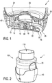
- Fig. 2 shows schematically and exemplarily a feeding bottle 100 as an example of a load determination device 1 comprising hull component 20 and sealing component 50 provided about a lower portion of feeding bottle 100.
- a feeding bottle 100 an opening 110 for inserting liquid into feeding bottle 100 is provided, of which the weight can be determined by the load cell component 10 (not visible in Fig. 2 ).
- Fig. 3 shows schematically and exemplarily a perspective cross-sectional view of load determination device 1, e.g. the exemplary feeding bottle 100 of Fig. 2 .
- Sealing component 50 is configured to seal load cell component 10 within load determination device 1, wherein sealing component 50 provides preferably a flexible, sealing connection between hull component 20 and base component 30.
- sealing component 50 comprises a hull portion 54 and a base portion 56, which are linked to each other by means of a bellows portion 52 surrounding base component 30.
- base portion 56 covers base component 30 on the lower surface thereof entirely, wherein in other examples sealing component 50 is only in contact with at least part of the surface of base component 30 or even only with a different part, for instance a side surface, thereof.
- bellows portion 52 surround base component 30 and seal gap 46 as described with reference to Fig. 1 .
- sealing component 50 does not directly transmit forces to load cell component 10, load cell component 10 is maintained supported on the surface by base component 30, even when base component 30 is partly or fully covered by sealing component 50 on the surface side thereof.
- further elements such as parts of sealing component 50 or other elements, can be provided between base component 30 and the surface without deteriorating the load determination by load cell component 10.
- one or more protruding noses can be provided on the lower surface of load determination device 1.
- the protruding noses can additionally reduce the risk of load determination device 1 gliding over its supporting surface, for example in case of a wet surface.
- three protrusions can be formed and be symetrically arranged on the lower surface side of base component 30 or, preferably, sealing component 50 covering base component 30.
- the number and arrangement of the protrusions is not limited to this example.
- Bellows portion 52 comprises in this example a single rotational symmetric rolling 58 between a lower side of an inner side wall 57 and an outer side wall 59, which is illustrated in more detail in Fig. 4 .
- Fig. 4 shows sealing component 50 in further detail.
- sealing component 50 is only provided to a certain extend over the lower surface of base component 30.
- An arrow 34 indicates that all gravitational loads of hull component 20 are transmitted through base component 30 and not through sealing component 50.
- Fig. 4 illustrates that the decoupling of loads both horizontally and vertically is achieved by sealing component 50, in particular by bellows portion 52 thereof.
- Dashed lines indicate the border between hull portion 54, which is attached or fixed to hull component 20, flexible bellows portion 52, which forms the seal, and fixed base portion 56, which is attached or fixed to based component 30, respectively.
- sealing component 50 is entirely formed of a low stiffness material, such as a rubber material.
- rolling 58 of bellows portion 52 provides very little resistance and thus transmission capabilities for loads applied to hull component 20 and thus hull portion 54 of sealing component 50 attached therewith.
- bellow portion 52 due to the rotational symmetric provision of bellow portion 52, also horizontal loads or forces applied to hull component 20 are not transmitted to base component 30 via sealing component 50, since the rolling 58 provides a favorably low resistance for such forces.
- the bellows arrangement with a single rolling 58 has proven to show less interference with load cell component 10 compared to other flexible sealing components like harmonica and trampoline archetypes. This can, for instance, be demonstrated through finite element simulations as indicated through different gradation of sealing component 50 in Fig. 4 .
- Load cell component 10 works by sensing small deformations, which are caused by the weight of hull component 20, i.e. gravitational loads caused therefrom, when it is placed on a horizontal surface with base component 30, either directly or covered with base portion 56 of sealing component 50.
- Load generated by hull component 20 includes loads or weight of matter reception component 22, for instance the container including the liquid, and housing parts 24, for instance.
- sealing component 50 In order to allow the weight of hull component 20 to be carried mostly by load cell component 10, a compliant bellow-like bellows portion 52 is provided in sealing component 50, which at least partly covers hull component 20 and base component 30.
- Sealing component 50 is preferably made from a low stiffness material, such as rubber, which is attached to a much stiffer material, for instance of hull component 20 or base component 30, except for bellows portion 52, in which sealing component 50 is not attached to a stiffer material.
- the strain in the preferably stiff load cell component 10 is determined by the weight and stiffness of the assembly, which would be unfavorable if the bellows portion 52 would be stiff and the area, in which the fixed portion 16 of load cell component 10 would be secured is flexible, since load cell component 10 would then feel very little of the weight. Instead, load cell component 10 would achieve the full sensitivity in the ideal case of a rigid fixation of load cell component 10 to hull component 20 and to base component 30, wherein sealing component 50 including bellows portions 52 consists of a very soft and thin material.
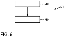
- Fig. 5 shows a flowchart exemplarily illustrating an embodiment of a method 500 of manufacturing a load determination device 1 according to the present invention.
- the method 500 comprises a step 510 of molding at least part of hull component 20 using a first material. Further, one, more or all of the elements of load cell component 10 and base component 30 can be molded in the same or consecutive stages.
- a further step 520 at least part of the hull component 20 is overmolded with the sealing component 50 using a second material in a 2K injection molding process.
- the 2K injection molding process allows a safe link between the first and second material, while at the same time being widely available and a well-understood process.
- a single unit or device may fulfill the functions of several items recited in the claims.
- the mere fact that certain measures are recited in mutually different dependent claims does not indicate that a combination of these measures cannot be used to advantage.
- a load determination device 1 comprising a load cell component 10, a hull component 20 of which the load is to be determined, the hull component 20 being provided in contact with the load cell component 10, a base component 30 for supporting the load cell component 10 on a surface, a sealing component 50 for sealing the load cell component 10 within the load determination device 1 being arranged in sealing connection between the hull component 20 and the base component 30, wherein the sealing component 50 comprises a bellows portion 52 surrounding the base component 30, wherein the bellows portion 52 comprises a rotational symmetric rolling 58 directed away from the surface.
- the load determination device 1 and a corresponding method for manufacturing such load determination device 1 provide an improved sealing of the load cell component 10.
Landscapes
- Physics & Mathematics (AREA)
- General Physics & Mathematics (AREA)
- Health & Medical Sciences (AREA)
- Life Sciences & Earth Sciences (AREA)
- Animal Behavior & Ethology (AREA)
- General Health & Medical Sciences (AREA)
- Public Health (AREA)
- Veterinary Medicine (AREA)
- Measurement Of Force In General (AREA)
- Force Measurement Appropriate To Specific Purposes (AREA)
Claims (15)
- Lastbestimmungsvorrichtung (1), wobei die Lastbestimmungsvorrichtung (1) umfasst:- eine Lastzellenkomponente (10), die einen Lastempfangsabschnitt (12), einen festen Abschnitt (16) und einen Lastbestimmungsabschnitt (14) umfasst, wobei der Lastbestimmungsabschnitt (14) zwischen dem Lastempfangsabschnitt (12) und dem festen Abschnitt (16) angeordnet ist,- eine Mantelkomponente (20), deren Last zu bestimmen ist, wobei die Mantelkomponente (20) in Kontakt mit dem Lastempfangsabschnitt (12) bereitgestellt ist,- eine Basiskomponente (30) zum Tragen der Lastzellenkomponente (10) auf einer Oberfläche, wobei die Basiskomponente (30) in Kontakt mit dem festen Abschnitt (16) bereitgestellt ist,- eine Abdichtungskomponente (50) zum Abdichten der Lastzellenkomponente (10) innerhalb der Lastbestimmungsvorrichtung (1), wobeidie Abdichtungskomponente (50) abdichtend verbindend zwischen der Mantelkomponente (20) und der Basiskomponente (30) angeordnet ist, dadurch gekennzeichnet, dass
die Abdichtungskomponente (50) einen Balgabschnitt (52) umfasst, der die Basiskomponente (30) umgibt, wobei
der Balgabschnitt (52) eine Rotationssymmetrierollung (58) umfasst, die von der Oberfläche weg gerichtet ist. - Lastbestimmungsvorrichtung (1) nach Anspruch 1, wobei die Rotationssymmetrierollung (58) eine vertikale Rollung umfasst.
- Lastbestimmungsvorrichtung (1) nach Anspruch 2, wobei die vertikale Rollung eine innere Seitenwand (57) und eine äußere Seitenwand (59) umfasst, wobei ein unteres Ende (26) der äußeren Seitenwand (59) so konfiguriert ist, dass es in Bezug auf die Oberfläche vertikal angehoben ist.
- Lastbestimmungsvorrichtung (1) nach Anspruch 1, wobei die Lastzellenkomponente (10) im Wesentlichen horizontal angeordnet ist, wobei der Lastbestimmungsabschnitt (14) auf einer Linie mit und zwischen dem Lastempfangsabschnitt (12) und dem festen Abschnitt (16) angeordnet ist.
- Lastbestimmungsvorrichtung (1) nach Anspruch 1, wobei die Basiskomponente (30) eine Kreisplatte umfasst, wobei die Rotationssymmetrierollung (58) die Kreisplatte umgibt.
- Lastbestimmungsvorrichtung (1) nach Anspruch 1, wobei der Balgabschnitt (52) horizontal direkt angrenzend an die Basiskomponente (30) bereitgestellt ist.
- Lastbestimmungsvorrichtung (1) nach Anspruch 1, wobei die Lastbestimmungsvorrichtung (1) ein Haushaltsprodukt ist.
- Lastbestimmungsvorrichtung (1) nach Anspruch 5, wobei das Haushaltsprodukt eine Fütterungsflasche (100) ist.
- Lastbestimmungsvorrichtung (1) nach Anspruch 1, wobei die Mantelkomponente (20) eine Materialaufnahmekomponente (22) umfasst, die einen Behälter einschließt, um darin Flüssigkeit aufzunehmen.
- Lastbestimmungsvorrichtung (1) nach Anspruch 1, wobei die Mantelkomponente (20) ein erstes Material, insbesondere ein erstes Kunststoffmaterial, umfasst, wobei das erste Material eine höhere Steifigkeit aufweist als die Abdichtungskomponente (50).
- Lastbestimmungsvorrichtung (1) nach Anspruch 1, wobei die Abdichtungskomponente (50) ein zweites Material, insbesondere ein zweites Kunststoffmaterial, umfasst, wobei das zweite Material eine geringere Steifigkeit aufweist als die Mantelkomponente (20) und/oder die Basiskomponente (30).
- Lastbestimmungsvorrichtung (1) nach Anspruch 1, wobei das zweite Material ein weichgummiartiges Material umfasst.
- Lastbestimmungsvorrichtung (1) nach Anspruch 1, wobei die Abdichtungskomponente (50) nur in einem Abschnitt, der von dem Balgabschnitt (52) verschieden ist, an Komponenten mit einer höheren Steifigkeit als die Abdichtungskomponente (50) befestigt ist.
- Lastbestimmungsvorrichtung (1) nach Anspruch 1, wobei zumindest ein Teil der Mantelkomponente (20) und der Abdichtungskomponente (50) in einem 2K-Spritzgießprozess hergestellt worden sind.
- Verfahren (500) zum Herstellen einer Lastbestimmungsvorrichtung (1) nach Anspruch 1, wobei das Verfahren umfasst:Formen (510) zumindest eines Teils der Mantelkomponente (20) unter Verwendung eines ersten Materials, undÜberformen (520) der Mantelkomponente (20) mit der Abdichtungskomponente (50) unter Verwendung eines zweiten Materials in einem 2K-Spritzgießprozess.
Applications Claiming Priority (2)
| Application Number | Priority Date | Filing Date | Title |
|---|---|---|---|
| EP17185515.8A EP3441729A1 (de) | 2017-08-09 | 2017-08-09 | Lastbestimmungsvorrichtung und zugehöriges herstellungsverfahren |
| PCT/EP2018/070534 WO2019030029A1 (en) | 2017-08-09 | 2018-07-30 | CHARGE DETERMINATION DEVICE AND METHOD OF MANUFACTURING THE SAME |
Publications (2)
| Publication Number | Publication Date |
|---|---|
| EP3665448A1 EP3665448A1 (de) | 2020-06-17 |
| EP3665448B1 true EP3665448B1 (de) | 2021-03-31 |
Family
ID=59579478
Family Applications (2)
| Application Number | Title | Priority Date | Filing Date |
|---|---|---|---|
| EP17185515.8A Withdrawn EP3441729A1 (de) | 2017-08-09 | 2017-08-09 | Lastbestimmungsvorrichtung und zugehöriges herstellungsverfahren |
| EP18743541.7A Active EP3665448B1 (de) | 2017-08-09 | 2018-07-30 | Lastbestimmungsvorrichtung und zugehöriges herstellungsverfahren |
Family Applications Before (1)
| Application Number | Title | Priority Date | Filing Date |
|---|---|---|---|
| EP17185515.8A Withdrawn EP3441729A1 (de) | 2017-08-09 | 2017-08-09 | Lastbestimmungsvorrichtung und zugehöriges herstellungsverfahren |
Country Status (5)
| Country | Link |
|---|---|
| US (1) | US11422023B2 (de) |
| EP (2) | EP3441729A1 (de) |
| CN (1) | CN111201424B (de) |
| RU (1) | RU2760509C2 (de) |
| WO (1) | WO2019030029A1 (de) |
Families Citing this family (1)
| Publication number | Priority date | Publication date | Assignee | Title |
|---|---|---|---|---|
| EP3992847A1 (de) | 2020-10-27 | 2022-05-04 | Koninklijke Philips N.V. | Flaschenanalysesystem |
Family Cites Families (25)
| Publication number | Priority date | Publication date | Assignee | Title |
|---|---|---|---|---|
| CA174700A (en) | 1916-02-29 | 1917-01-23 | G. R. Lawrence | Power and control mechanism |
| US3196676A (en) * | 1962-12-31 | 1965-07-27 | Baldwin Lima Hamilton Corp | Shear strain type force measuring device |
| GB1494495A (en) * | 1974-05-16 | 1977-12-07 | Darenth Weighing Equipment Ltd | Apparatus for supporting and measuring loads |
| US4383584A (en) * | 1980-02-15 | 1983-05-17 | International Road Dynamics Inc. | Sealed load cell construction |
| GB2150307B (en) | 1983-11-21 | 1988-09-01 | Kubota Ltd | Load cell having flameproof enclosure |
| JPS60118927U (ja) * | 1984-01-13 | 1985-08-12 | 寺岡 武治 | 台秤 |
| US5319161A (en) * | 1992-12-24 | 1994-06-07 | Pitney Bowes Inc. | Mechanism for preventing overload on a weighing scale |
| DE20018255U1 (de) | 2000-10-25 | 2001-01-04 | Universal Weight Enterprise Co., Ltd., Hsin Tien, Taipeh | Wassergeschützte elektronische Waage |
| JP3830420B2 (ja) * | 2002-05-14 | 2006-10-04 | 株式会社タニタ | 防水型秤 |
| US6789435B2 (en) | 2002-10-01 | 2004-09-14 | Hottinger Baldwin Measurements, Inc. | Hermetically sealed load cell |
| JP2006071391A (ja) * | 2004-09-01 | 2006-03-16 | Yamato Scale Co Ltd | 防水式電子秤 |
| CN200968879Y (zh) * | 2006-06-26 | 2007-10-31 | 上海壹衡电子衡器有限公司 | 带传感器防护装置的电子台秤 |
| JP2010096502A (ja) * | 2008-10-14 | 2010-04-30 | Yamato Scale Co Ltd | 計量器 |
| DE102008064169B4 (de) * | 2008-12-22 | 2013-07-18 | Hottinger Baldwin Messtechnik Gmbh | Wägezelle |
| CN201653508U (zh) * | 2009-06-25 | 2010-11-24 | 营口大和衡器有限公司 | 真空式称重传感器 |
| CN201795855U (zh) * | 2010-03-22 | 2011-04-13 | 东莞桥头安迅电子厂 | 一种食品制作测量仪器 |
| DE102010014152B4 (de) * | 2010-04-07 | 2015-12-24 | Hottinger Baldwin Messtechnik Gmbh | Wägezelle |
| CN201765047U (zh) * | 2010-07-08 | 2011-03-16 | 浙江华潮电器有限公司 | 电子厨房秤 |
| EP2700918A1 (de) * | 2012-08-23 | 2014-02-26 | Mettler-Toledo (Albstadt) GmbH | Waage mit gasdurchlässigem Dichtmodul |
| CN103674212B (zh) * | 2012-09-19 | 2017-11-28 | 梅特勒-托利多有限公司 | 测力计称重模块 |
| GB2513136A (en) * | 2013-04-16 | 2014-10-22 | Lakeland Ltd | Weighing Scales |
| DE102013105647B4 (de) * | 2013-05-31 | 2014-12-11 | Wipotec Wiege- Und Positioniersysteme Gmbh | Gehäuse für eine Wägevorrichtung |
| CN104776900B (zh) | 2015-03-13 | 2017-09-22 | 康凯 | 一种防水智能奶瓶套及其密闭式防水称重结构 |
| USD844158S1 (en) | 2016-12-26 | 2019-03-26 | Koninklijke Philips N.V. | Sleeve for baby bottle |
| CN206300717U (zh) * | 2016-12-26 | 2017-07-04 | 杭州塘树科技有限公司 | 一种天平减震器 |
-
2017
- 2017-08-09 EP EP17185515.8A patent/EP3441729A1/de not_active Withdrawn
-
2018
- 2018-07-30 EP EP18743541.7A patent/EP3665448B1/de active Active
- 2018-07-30 RU RU2020109996A patent/RU2760509C2/ru active
- 2018-07-30 US US16/636,351 patent/US11422023B2/en active Active
- 2018-07-30 CN CN201880065577.7A patent/CN111201424B/zh active Active
- 2018-07-30 WO PCT/EP2018/070534 patent/WO2019030029A1/en not_active Ceased
Non-Patent Citations (1)
| Title |
|---|
| None * |
Also Published As
| Publication number | Publication date |
|---|---|
| RU2020109996A (ru) | 2021-09-10 |
| US20200166402A1 (en) | 2020-05-28 |
| EP3441729A1 (de) | 2019-02-13 |
| RU2020109996A3 (de) | 2021-09-10 |
| EP3665448A1 (de) | 2020-06-17 |
| WO2019030029A1 (en) | 2019-02-14 |
| US11422023B2 (en) | 2022-08-23 |
| CN111201424B (zh) | 2022-01-28 |
| RU2760509C2 (ru) | 2021-11-25 |
| CN111201424A (zh) | 2020-05-26 |
Similar Documents
| Publication | Publication Date | Title |
|---|---|---|
| US20160069737A1 (en) | Weighing Scales | |
| CN102589791B (zh) | 具有低成本封装的压力传感器 | |
| US7554043B2 (en) | Weighing scale having dual housings | |
| JP6041635B2 (ja) | 計量装置 | |
| EP3290571B1 (de) | Sensorvorrichtung und elektrisches gerät zum waschen und mit dieser sensorvorrichtung | |
| EP3665448B1 (de) | Lastbestimmungsvorrichtung und zugehöriges herstellungsverfahren | |
| US20120125116A1 (en) | Sensor | |
| JP5628526B2 (ja) | 電子秤 | |
| CN204188251U (zh) | 一种防水称重装置 | |
| EP3333559B1 (de) | Messvorrichtung für physikalische groessen | |
| JPS62179615A (ja) | 高分解能秤量装置 | |
| JP2006071391A (ja) | 防水式電子秤 | |
| US20230125314A1 (en) | Strain sensor assembly | |
| CN107684348B (zh) | 一种内锅和烹饪器具 | |
| JP4204947B2 (ja) | 秤 | |
| EP3623819B1 (de) | Vorrichtung zum erfassen einer bewegung eines objekts in bezug auf ein fluid | |
| JP5062799B2 (ja) | 秤量装置用一体型筐体 | |
| US20230023999A1 (en) | Submersion Sensor | |
| JP5080344B2 (ja) | 防水秤及びそれに用いる計量ブロック | |
| JP3233096B2 (ja) | 防水型電子秤 | |
| JP2005140625A (ja) | 秤 | |
| JP7704909B2 (ja) | 冷温水機 | |
| KR100900801B1 (ko) | 음식물 쓰레기 수거차량에 장착되는 계근기 | |
| KR101033836B1 (ko) | 음식물 쓰레기 수거차량용 계근기 | |
| JPH04307369A (ja) | 加速度センサ |
Legal Events
| Date | Code | Title | Description |
|---|---|---|---|
| STAA | Information on the status of an ep patent application or granted ep patent |
Free format text: STATUS: UNKNOWN |
|
| STAA | Information on the status of an ep patent application or granted ep patent |
Free format text: STATUS: THE INTERNATIONAL PUBLICATION HAS BEEN MADE |
|
| PUAI | Public reference made under article 153(3) epc to a published international application that has entered the european phase |
Free format text: ORIGINAL CODE: 0009012 |
|
| STAA | Information on the status of an ep patent application or granted ep patent |
Free format text: STATUS: REQUEST FOR EXAMINATION WAS MADE |
|
| 17P | Request for examination filed |
Effective date: 20200309 |
|
| AK | Designated contracting states |
Kind code of ref document: A1 Designated state(s): AL AT BE BG CH CY CZ DE DK EE ES FI FR GB GR HR HU IE IS IT LI LT LU LV MC MK MT NL NO PL PT RO RS SE SI SK SM TR |
|
| AX | Request for extension of the european patent |
Extension state: BA ME |
|
| GRAP | Despatch of communication of intention to grant a patent |
Free format text: ORIGINAL CODE: EPIDOSNIGR1 |
|
| STAA | Information on the status of an ep patent application or granted ep patent |
Free format text: STATUS: GRANT OF PATENT IS INTENDED |
|
| DAV | Request for validation of the european patent (deleted) | ||
| DAX | Request for extension of the european patent (deleted) | ||
| INTG | Intention to grant announced |
Effective date: 20201020 |
|
| GRAS | Grant fee paid |
Free format text: ORIGINAL CODE: EPIDOSNIGR3 |
|
| GRAA | (expected) grant |
Free format text: ORIGINAL CODE: 0009210 |
|
| STAA | Information on the status of an ep patent application or granted ep patent |
Free format text: STATUS: THE PATENT HAS BEEN GRANTED |
|
| AK | Designated contracting states |
Kind code of ref document: B1 Designated state(s): AL AT BE BG CH CY CZ DE DK EE ES FI FR GB GR HR HU IE IS IT LI LT LU LV MC MK MT NL NO PL PT RO RS SE SI SK SM TR |
|
| REG | Reference to a national code |
Ref country code: GB Ref legal event code: FG4D Ref country code: CH Ref legal event code: EP |
|
| REG | Reference to a national code |
Ref country code: AT Ref legal event code: REF Ref document number: 1377447 Country of ref document: AT Kind code of ref document: T Effective date: 20210415 |
|
| REG | Reference to a national code |
Ref country code: DE Ref legal event code: R096 Ref document number: 602018014849 Country of ref document: DE |
|
| REG | Reference to a national code |
Ref country code: IE Ref legal event code: FG4D |
|
| REG | Reference to a national code |
Ref country code: LT Ref legal event code: MG9D |
|
| PG25 | Lapsed in a contracting state [announced via postgrant information from national office to epo] |
Ref country code: BG Free format text: LAPSE BECAUSE OF FAILURE TO SUBMIT A TRANSLATION OF THE DESCRIPTION OR TO PAY THE FEE WITHIN THE PRESCRIBED TIME-LIMIT Effective date: 20210630 Ref country code: HR Free format text: LAPSE BECAUSE OF FAILURE TO SUBMIT A TRANSLATION OF THE DESCRIPTION OR TO PAY THE FEE WITHIN THE PRESCRIBED TIME-LIMIT Effective date: 20210331 Ref country code: FI Free format text: LAPSE BECAUSE OF FAILURE TO SUBMIT A TRANSLATION OF THE DESCRIPTION OR TO PAY THE FEE WITHIN THE PRESCRIBED TIME-LIMIT Effective date: 20210331 Ref country code: NO Free format text: LAPSE BECAUSE OF FAILURE TO SUBMIT A TRANSLATION OF THE DESCRIPTION OR TO PAY THE FEE WITHIN THE PRESCRIBED TIME-LIMIT Effective date: 20210630 |
|
| PG25 | Lapsed in a contracting state [announced via postgrant information from national office to epo] |
Ref country code: SE Free format text: LAPSE BECAUSE OF FAILURE TO SUBMIT A TRANSLATION OF THE DESCRIPTION OR TO PAY THE FEE WITHIN THE PRESCRIBED TIME-LIMIT Effective date: 20210331 Ref country code: RS Free format text: LAPSE BECAUSE OF FAILURE TO SUBMIT A TRANSLATION OF THE DESCRIPTION OR TO PAY THE FEE WITHIN THE PRESCRIBED TIME-LIMIT Effective date: 20210331 Ref country code: LV Free format text: LAPSE BECAUSE OF FAILURE TO SUBMIT A TRANSLATION OF THE DESCRIPTION OR TO PAY THE FEE WITHIN THE PRESCRIBED TIME-LIMIT Effective date: 20210331 |
|
| REG | Reference to a national code |
Ref country code: NL Ref legal event code: MP Effective date: 20210331 |
|
| REG | Reference to a national code |
Ref country code: AT Ref legal event code: MK05 Ref document number: 1377447 Country of ref document: AT Kind code of ref document: T Effective date: 20210331 |
|
| PG25 | Lapsed in a contracting state [announced via postgrant information from national office to epo] |
Ref country code: LT Free format text: LAPSE BECAUSE OF FAILURE TO SUBMIT A TRANSLATION OF THE DESCRIPTION OR TO PAY THE FEE WITHIN THE PRESCRIBED TIME-LIMIT Effective date: 20210331 Ref country code: CZ Free format text: LAPSE BECAUSE OF FAILURE TO SUBMIT A TRANSLATION OF THE DESCRIPTION OR TO PAY THE FEE WITHIN THE PRESCRIBED TIME-LIMIT Effective date: 20210331 Ref country code: EE Free format text: LAPSE BECAUSE OF FAILURE TO SUBMIT A TRANSLATION OF THE DESCRIPTION OR TO PAY THE FEE WITHIN THE PRESCRIBED TIME-LIMIT Effective date: 20210331 Ref country code: SM Free format text: LAPSE BECAUSE OF FAILURE TO SUBMIT A TRANSLATION OF THE DESCRIPTION OR TO PAY THE FEE WITHIN THE PRESCRIBED TIME-LIMIT Effective date: 20210331 Ref country code: NL Free format text: LAPSE BECAUSE OF FAILURE TO SUBMIT A TRANSLATION OF THE DESCRIPTION OR TO PAY THE FEE WITHIN THE PRESCRIBED TIME-LIMIT Effective date: 20210331 Ref country code: AT Free format text: LAPSE BECAUSE OF FAILURE TO SUBMIT A TRANSLATION OF THE DESCRIPTION OR TO PAY THE FEE WITHIN THE PRESCRIBED TIME-LIMIT Effective date: 20210331 |
|
| PG25 | Lapsed in a contracting state [announced via postgrant information from national office to epo] |
Ref country code: SK Free format text: LAPSE BECAUSE OF FAILURE TO SUBMIT A TRANSLATION OF THE DESCRIPTION OR TO PAY THE FEE WITHIN THE PRESCRIBED TIME-LIMIT Effective date: 20210331 Ref country code: PT Free format text: LAPSE BECAUSE OF FAILURE TO SUBMIT A TRANSLATION OF THE DESCRIPTION OR TO PAY THE FEE WITHIN THE PRESCRIBED TIME-LIMIT Effective date: 20210802 Ref country code: RO Free format text: LAPSE BECAUSE OF FAILURE TO SUBMIT A TRANSLATION OF THE DESCRIPTION OR TO PAY THE FEE WITHIN THE PRESCRIBED TIME-LIMIT Effective date: 20210331 Ref country code: PL Free format text: LAPSE BECAUSE OF FAILURE TO SUBMIT A TRANSLATION OF THE DESCRIPTION OR TO PAY THE FEE WITHIN THE PRESCRIBED TIME-LIMIT Effective date: 20210331 Ref country code: IS Free format text: LAPSE BECAUSE OF FAILURE TO SUBMIT A TRANSLATION OF THE DESCRIPTION OR TO PAY THE FEE WITHIN THE PRESCRIBED TIME-LIMIT Effective date: 20210731 |
|
| REG | Reference to a national code |
Ref country code: DE Ref legal event code: R097 Ref document number: 602018014849 Country of ref document: DE |
|
| PG25 | Lapsed in a contracting state [announced via postgrant information from national office to epo] |
Ref country code: ES Free format text: LAPSE BECAUSE OF FAILURE TO SUBMIT A TRANSLATION OF THE DESCRIPTION OR TO PAY THE FEE WITHIN THE PRESCRIBED TIME-LIMIT Effective date: 20210331 Ref country code: DK Free format text: LAPSE BECAUSE OF FAILURE TO SUBMIT A TRANSLATION OF THE DESCRIPTION OR TO PAY THE FEE WITHIN THE PRESCRIBED TIME-LIMIT Effective date: 20210331 Ref country code: AL Free format text: LAPSE BECAUSE OF FAILURE TO SUBMIT A TRANSLATION OF THE DESCRIPTION OR TO PAY THE FEE WITHIN THE PRESCRIBED TIME-LIMIT Effective date: 20210331 |
|
| PLBE | No opposition filed within time limit |
Free format text: ORIGINAL CODE: 0009261 |
|
| STAA | Information on the status of an ep patent application or granted ep patent |
Free format text: STATUS: NO OPPOSITION FILED WITHIN TIME LIMIT |
|
| REG | Reference to a national code |
Ref country code: CH Ref legal event code: PL |
|
| 26N | No opposition filed |
Effective date: 20220104 |
|
| PG25 | Lapsed in a contracting state [announced via postgrant information from national office to epo] |
Ref country code: MC Free format text: LAPSE BECAUSE OF FAILURE TO SUBMIT A TRANSLATION OF THE DESCRIPTION OR TO PAY THE FEE WITHIN THE PRESCRIBED TIME-LIMIT Effective date: 20210331 |
|
| REG | Reference to a national code |
Ref country code: BE Ref legal event code: MM Effective date: 20210731 |
|
| PG25 | Lapsed in a contracting state [announced via postgrant information from national office to epo] |
Ref country code: LI Free format text: LAPSE BECAUSE OF NON-PAYMENT OF DUE FEES Effective date: 20210731 Ref country code: CH Free format text: LAPSE BECAUSE OF NON-PAYMENT OF DUE FEES Effective date: 20210731 |
|
| PG25 | Lapsed in a contracting state [announced via postgrant information from national office to epo] |
Ref country code: IS Free format text: LAPSE BECAUSE OF FAILURE TO SUBMIT A TRANSLATION OF THE DESCRIPTION OR TO PAY THE FEE WITHIN THE PRESCRIBED TIME-LIMIT Effective date: 20210731 Ref country code: LU Free format text: LAPSE BECAUSE OF NON-PAYMENT OF DUE FEES Effective date: 20210730 |
|
| PG25 | Lapsed in a contracting state [announced via postgrant information from national office to epo] |
Ref country code: IT Free format text: LAPSE BECAUSE OF FAILURE TO SUBMIT A TRANSLATION OF THE DESCRIPTION OR TO PAY THE FEE WITHIN THE PRESCRIBED TIME-LIMIT Effective date: 20210331 Ref country code: IE Free format text: LAPSE BECAUSE OF NON-PAYMENT OF DUE FEES Effective date: 20210730 Ref country code: BE Free format text: LAPSE BECAUSE OF NON-PAYMENT OF DUE FEES Effective date: 20210731 |
|
| GBPC | Gb: european patent ceased through non-payment of renewal fee |
Effective date: 20220730 |
|
| PG25 | Lapsed in a contracting state [announced via postgrant information from national office to epo] |
Ref country code: GB Free format text: LAPSE BECAUSE OF NON-PAYMENT OF DUE FEES Effective date: 20220730 |
|
| PG25 | Lapsed in a contracting state [announced via postgrant information from national office to epo] |
Ref country code: CY Free format text: LAPSE BECAUSE OF FAILURE TO SUBMIT A TRANSLATION OF THE DESCRIPTION OR TO PAY THE FEE WITHIN THE PRESCRIBED TIME-LIMIT Effective date: 20210331 |
|
| PG25 | Lapsed in a contracting state [announced via postgrant information from national office to epo] |
Ref country code: HU Free format text: LAPSE BECAUSE OF FAILURE TO SUBMIT A TRANSLATION OF THE DESCRIPTION OR TO PAY THE FEE WITHIN THE PRESCRIBED TIME-LIMIT; INVALID AB INITIO Effective date: 20180730 Ref country code: GR Free format text: LAPSE BECAUSE OF FAILURE TO SUBMIT A TRANSLATION OF THE DESCRIPTION OR TO PAY THE FEE WITHIN THE PRESCRIBED TIME-LIMIT Effective date: 20210331 |
|
| PG25 | Lapsed in a contracting state [announced via postgrant information from national office to epo] |
Ref country code: MK Free format text: LAPSE BECAUSE OF FAILURE TO SUBMIT A TRANSLATION OF THE DESCRIPTION OR TO PAY THE FEE WITHIN THE PRESCRIBED TIME-LIMIT Effective date: 20210331 |
|
| PG25 | Lapsed in a contracting state [announced via postgrant information from national office to epo] |
Ref country code: MT Free format text: LAPSE BECAUSE OF FAILURE TO SUBMIT A TRANSLATION OF THE DESCRIPTION OR TO PAY THE FEE WITHIN THE PRESCRIBED TIME-LIMIT Effective date: 20210331 |
|
| PGFP | Annual fee paid to national office [announced via postgrant information from national office to epo] |
Ref country code: DE Payment date: 20250728 Year of fee payment: 8 |
|
| PGFP | Annual fee paid to national office [announced via postgrant information from national office to epo] |
Ref country code: FR Payment date: 20250725 Year of fee payment: 8 |
|
| PG25 | Lapsed in a contracting state [announced via postgrant information from national office to epo] |
Ref country code: TR Free format text: LAPSE BECAUSE OF FAILURE TO SUBMIT A TRANSLATION OF THE DESCRIPTION OR TO PAY THE FEE WITHIN THE PRESCRIBED TIME-LIMIT Effective date: 20210331 |