EP3665443B1 - Débitmètre et canal de mesure - Google Patents
Débitmètre et canal de mesure Download PDFInfo
- Publication number
- EP3665443B1 EP3665443B1 EP18752149.7A EP18752149A EP3665443B1 EP 3665443 B1 EP3665443 B1 EP 3665443B1 EP 18752149 A EP18752149 A EP 18752149A EP 3665443 B1 EP3665443 B1 EP 3665443B1
- Authority
- EP
- European Patent Office
- Prior art keywords
- measuring channel
- flow meter
- measuring
- meter according
- profile
- Prior art date
- Legal status (The legal status is an assumption and is not a legal conclusion. Google has not performed a legal analysis and makes no representation as to the accuracy of the status listed.)
- Active
Links
- 238000010168 coupling process Methods 0.000 claims description 15
- 238000005859 coupling reaction Methods 0.000 claims description 15
- 230000008878 coupling Effects 0.000 claims description 13
- 230000007704 transition Effects 0.000 claims description 7
- 230000005484 gravity Effects 0.000 claims description 3
- 238000005259 measurement Methods 0.000 description 11
- 238000004519 manufacturing process Methods 0.000 description 9
- 238000000034 method Methods 0.000 description 7
- 239000000463 material Substances 0.000 description 4
- 238000004026 adhesive bonding Methods 0.000 description 2
- 238000013461 design Methods 0.000 description 2
- 239000012530 fluid Substances 0.000 description 2
- 238000003698 laser cutting Methods 0.000 description 2
- 230000002093 peripheral effect Effects 0.000 description 2
- 239000007858 starting material Substances 0.000 description 2
- XLYOFNOQVPJJNP-UHFFFAOYSA-N water Substances O XLYOFNOQVPJJNP-UHFFFAOYSA-N 0.000 description 2
- 238000003466 welding Methods 0.000 description 2
- 229910001369 Brass Inorganic materials 0.000 description 1
- RYGMFSIKBFXOCR-UHFFFAOYSA-N Copper Chemical compound [Cu] RYGMFSIKBFXOCR-UHFFFAOYSA-N 0.000 description 1
- 241000792859 Enema Species 0.000 description 1
- 229910000831 Steel Inorganic materials 0.000 description 1
- RTAQQCXQSZGOHL-UHFFFAOYSA-N Titanium Chemical compound [Ti] RTAQQCXQSZGOHL-UHFFFAOYSA-N 0.000 description 1
- 238000009825 accumulation Methods 0.000 description 1
- 229910045601 alloy Inorganic materials 0.000 description 1
- 239000000956 alloy Substances 0.000 description 1
- 229910052782 aluminium Inorganic materials 0.000 description 1
- XAGFODPZIPBFFR-UHFFFAOYSA-N aluminium Chemical compound [Al] XAGFODPZIPBFFR-UHFFFAOYSA-N 0.000 description 1
- 239000010951 brass Substances 0.000 description 1
- 229910052802 copper Inorganic materials 0.000 description 1
- 239000010949 copper Substances 0.000 description 1
- 230000001419 dependent effect Effects 0.000 description 1
- 238000011161 development Methods 0.000 description 1
- 230000018109 developmental process Effects 0.000 description 1
- 238000005553 drilling Methods 0.000 description 1
- 230000000694 effects Effects 0.000 description 1
- 239000007920 enema Substances 0.000 description 1
- 229940095399 enema Drugs 0.000 description 1
- 238000005516 engineering process Methods 0.000 description 1
- 238000009434 installation Methods 0.000 description 1
- 239000007769 metal material Substances 0.000 description 1
- 238000012805 post-processing Methods 0.000 description 1
- 239000011265 semifinished product Substances 0.000 description 1
- 239000010935 stainless steel Substances 0.000 description 1
- 229910001220 stainless steel Inorganic materials 0.000 description 1
- 239000010959 steel Substances 0.000 description 1
- 239000002344 surface layer Substances 0.000 description 1
- 239000010936 titanium Substances 0.000 description 1
- 229910052719 titanium Inorganic materials 0.000 description 1
- 238000002604 ultrasonography Methods 0.000 description 1
Images

Classifications
-
- G—PHYSICS
- G01—MEASURING; TESTING
- G01F—MEASURING VOLUME, VOLUME FLOW, MASS FLOW OR LIQUID LEVEL; METERING BY VOLUME
- G01F1/00—Measuring the volume flow or mass flow of fluid or fluent solid material wherein the fluid passes through a meter in a continuous flow
- G01F1/66—Measuring the volume flow or mass flow of fluid or fluent solid material wherein the fluid passes through a meter in a continuous flow by measuring frequency, phase shift or propagation time of electromagnetic or other waves, e.g. using ultrasonic flowmeters
- G01F1/662—Constructional details
-
- G—PHYSICS
- G01—MEASURING; TESTING
- G01F—MEASURING VOLUME, VOLUME FLOW, MASS FLOW OR LIQUID LEVEL; METERING BY VOLUME
- G01F1/00—Measuring the volume flow or mass flow of fluid or fluent solid material wherein the fluid passes through a meter in a continuous flow
- G01F1/76—Devices for measuring mass flow of a fluid or a fluent solid material
- G01F1/78—Direct mass flowmeters
- G01F1/80—Direct mass flowmeters operating by measuring pressure, force, momentum, or frequency of a fluid flow to which a rotational movement has been imparted
- G01F1/84—Coriolis or gyroscopic mass flowmeters
-
- G—PHYSICS
- G01—MEASURING; TESTING
- G01F—MEASURING VOLUME, VOLUME FLOW, MASS FLOW OR LIQUID LEVEL; METERING BY VOLUME
- G01F15/00—Details of, or accessories for, apparatus of groups G01F1/00 - G01F13/00 insofar as such details or appliances are not adapted to particular types of such apparatus
Definitions
- the invention relates to a flow meter for measuring the flow of fluids in a pipeline or the like according to the preamble of patent claim 1, and a suitable measuring channel.
- EP 2 306 160 A1 discloses a flow meter/flow meter in which the measuring insert accommodates both the ultrasonic converter and forms the actual measuring channel.
- the flow guidance within the measuring channel is determined by a housing insert which can be inserted from the end face of the housing and which also carries reflectors for the ultrasonic signals, so that the ultrasound is emitted by one of the ultrasonic transducers and transmitted via the reflectors to the other, for example downstream ultrasonic transducer is reflected.
- the signal can also be routed in the opposite direction.
- a disadvantage of such solutions is that the measuring channel consists of materials that require a great deal of effort in the manufacturing process.
- the pamphlet U.S. 9,689,727 B2 shows an ultrasonic flowmeter with a measuring tube, the basic cross-section of which is manufactured by applying internal high pressure, i.e. by means of hydroforming. After the hydroforming, a flow drilling process is used to create recesses in the wall of the measuring tube, in which recesses ultrasonic sensors are inserted.
- the measuring tube has a larger nominal diameter in the area of its inlet and outlet than in the area of the recesses or the sensors used.
- inwardly curved reflection zones are formed as a result of the hydroforming.
- This configuration is in accordance with U.S. 9,689,727 B2 achieved by expanding the complete measuring tube during hydroforming.
- the nominal diameter of the starting material is chosen so small that the inward-facing reflective surfaces can remain.
- the invention is based on the object of creating a flow meter/flow counter and a measuring channel that can be produced with little effort in terms of production and process technology.
- the object is achieved according to the invention in that the measuring channel is produced by hydroforming.
- the hydroforming manufacturing process ensures that a relatively thin-walled measuring channel can be manufactured in one production step, regardless of the required size of the measuring channel.
- the manufacturing process can be used regardless of whether it is a measuring channel for a domestic water meter (from DN15) or a bulk water meter (up to DN300).
- Hydroforming is conceivable for measuring channels with a wide range of outer tube wall thicknesses.
- Various metallic materials as the starting material for the pipe allow a wide range of variants and do not require any post-processing.
- Another advantage compared to cast measuring channels is that a more finely structured surface layer is achieved, so that less turbulence can occur in the area of the measuring channel, which would impair the measuring accuracy.
- a hydroformed profile can be adapted to different conditions, whereby the same initial profile can always be used.
- the measuring channel has at least two recesses for accommodating a measuring device. These are spaced apart from one another in the direction of flow on one side of the measuring channel.
- the recesses can, for example, be in the form of elongated holes and can be introduced in the course of the hydroforming.
- the recesses for accommodating a measuring device are dispensed with, so that the sound can be heard through the wall of the measuring channel.
- a cross-sectional profile of the measuring channel is designed with a larger clear width along the direction of flow than transversely thereto.
- the tube diameter is brought into the shape described above.
- these are designed with a rounded design. This applies both to the area from the round tube to the cross-sectional profile mentioned above, as well as in the area of the transitions between the long and narrow side walls of the measuring channel.
- the hydroforming process makes it possible to shape the measuring channel in one step. Only a tube is required as a semi-finished product from which the measuring channel is made in one piece.
- the tube can be designed with a round cross section or with a rectangular or square cross section or in some other way. Both a variant with and without a flange can be implemented in one production step. According to the invention, it is preferred if the connection flanges are formed in a production step following the hydroforming.
- connection flange can be formed in each case by a type of flanging process on the measurement channel itself or by subsequent attachment, for example by welding, shrinking, or gluing of the separately manufactured connection flanges to the measurement channel.
- the measuring channel is formed in such a way that an approximately roof-shaped bulge preferably occurs on one side, the recesses for the sensors then being arranged in the region of two inclined walls of the bulge arranged obliquely to one another.
- the sensors are arranged in the area of the bulge.
- a particular advantage of this design is that the sensors are then arranged at an angle, so that the signals are coupled into and out of the measuring channel at a corresponding angle.
- the alignment of the sensors compared to a straight measuring channel without curvature is considerably easier.
- the approximately rectangular profile is arranged horizontally, so that the smaller width runs in the vertical direction (direction of gravity).
- a measuring channel for a flow meter is produced by hydroforming.
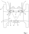
- figure 1 1 shows a longitudinal section of a flow meter 1.
- This representation shows two coupling pieces 2, 4 with two sensors 6 and 8, respectively. These are each inserted in two recesses 10a, 10b.
- the coupling surfaces 12 run flush with the peripheral wall (transverse wall 14 and adjacent areas of a side wall 16) of a measuring channel 18, which is formed by a piece of pipe 20 in this exemplary embodiment.
- a part of a flange 22 thus forms the transverse wall 14 .
- An opposite transverse wall 24 is formed in this embodiment with a pocket 26 open to the outside, in which a reflector 28 is inserted.
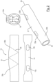
- FIG 2 a measuring channel 18, here without a flange, is shown, which was produced by hydroforming.
- the two recesses 10a, 10b can be clearly seen.
- Top right in figure 1 a cross section of the measuring channel is shown, from which it can be seen that in the flow area of the measuring channel 18 the clear height h is greater than the width b.
- the cross-sectional profile (top right) is shown such that the height h runs vertically (direction of gravity), so that the rectangular profile is arranged upright, so to speak. In field installation, however, it is preferred if the profile is installed "lying" so that the smaller width b is located in the vertical direction. This lying position of use offers the advantage that no accumulation of air can occur in the area of the recesses 10a, which would lead to an erroneous measurement.
- the transitions 30a in the area of the measuring channel and the transitions 30b in the transition area from the initial profile to the area of the measuring channel 18 are rounded.
- the raw part as the starting profile is a round profile for each measuring channel.
- All hydroformable materials are conceivable as materials, i.e. steel, stainless steel, special alloys, aluminum, copper, brass, or even titanium.
- the hydroforming transforms the initial profile, for example a round profile (tube) into the shape of the measuring channel 18 , while remaining a round profile (initial profile) in the area of the inlet 34 and the outlet 36 .
- the measuring channel 18 can be produced both with and without a flange 22. Due to the very low tension and springback, hydroforming achieves a very high level of dimensional accuracy.
- the flanges 22 may also be formed by a post process such as a flare process.
- the flanges can also be connected to the measuring channel formed by hydroforming by welding, shrinking, gluing or in some other way.
- the special shape of the measuring channel 18 can also be seen.
- the recesses 10a, 10b are formed.
- This bulge 31 can significantly facilitate the positioning and alignment of the sensors 6, 8 and the coupling pieces 2, 4, in contrast to a measuring channel 18 without a bulge 31.
- the recesses 10 are arranged on inclined walls 33 due to the shape of the bulge 31 .
- the recesses 10 arranged in this way make it possible for the signals from the sensors 6, 8 to then be able to couple into and out of the measuring channel 18 at an adapted angle.
- a different reflector arrangement can be used than in the exemplary embodiment described above.
- a reflector arrangement with three reflectors is installed instead of just one reflector 18 on the transverse wall 24 opposite the sensors 6, 8. Two of the reflectors 18 are formed on the transverse wall 24 and one reflector 18 between the sensors 6, 8 in the area of the bulge 31, so that a W-shaped signal path 35 is formed, as in FIG 2 indicated (reflectors are not shown).
- a reflector arrangement is provided 1 actionable.
- the representations in figure 3 show two exemplary embodiments of a measuring channel, one with the dimension DN50 and one with the dimension DN100.
- two pairs of sensors 6, 6′ and 8, 8′ are arranged in each coupling piece 2, 4, so that measurement signals are coupled in and out in parallel.
- a difference between the two embodiments according to figure 3 consists in the fact that with the nominal width DN50 the coupling pieces 2, 4 encompass a comparatively large part of the outer wall of the measuring channel due to the relatively small measuring channel cross section, the distance between the sensors 6, 6' and 8, 8' with the smaller nominal diameter is less than with the large nominal diameter DN100, so that the measuring signals are coupled in and out at a greater distance from one another.
- the coupling pieces 2, 4 are completely in the area of the transverse wall 14.
- the coupling pieces 2, 4 with the sensors 6, 6', 8, 8' are inserted in the recesses 10 provided for this purpose.
- the recesses 10 can also be produced from the initial profile, independently of the material, in one production step during hydroforming. In a preferred exemplary embodiment, however, the recesses 10 are only formed after the hydroforming, for example by laser cutting or in some other way.
- the transitions 32 from the transverse walls 14, 24 to the side walls 16, inside the measuring channel 18, are also designed as rounded portions.
- a flow meter is disclosed with at least two measuring sensors, preferably ultrasonic sensors, spaced apart from one another, the measuring signals being coupled in and out of a fluid via a coupling piece which is inserted into a peripheral wall of a measuring channel produced by hydroforming.
- the measurement signals can also be coupled and decoupled through a wall of the measurement channel.
Landscapes
- Physics & Mathematics (AREA)
- Fluid Mechanics (AREA)
- General Physics & Mathematics (AREA)
- Electromagnetism (AREA)
- Measuring Volume Flow (AREA)
Claims (11)
- Débitmètre, dans lequel un profil de section transversale d'un canal de mesure (18) est formé par hydroformage, dans lequel le canal de mesure (18) présente des évidements (10a, 10b) pour des capteurs (6, 8) logés dans des pièces de couplage (2, 4), caractérisé en ce qu' une seule zone du canal de mesure (18) est hydroformée, qui ne se trouve pas dans la zone d'une entrée (34) et d'une sortie (36), de sorte que le profil de section transversale dans la zone de l'entrée (34) et de la sortie (36) est un profil initial.
- Débitmètre selon la revendication 1, caractérisé en ce que le canal de mesure (18) présente une section transversale non ronde dans la zone des évidements (10a, 10b).
- Débitmètre selon la revendication 2, caractérisé en ce que la section transversale présente une hauteur (h) supérieure à la largeur (b) sensiblement dans la direction de couplage/découplage de signaux de mesure.
- Débitmètre selon la revendication 3, caractérisé en ce que dans la position d'utilisation, la section transversale est agencée horizontalement, de sorte que la plus petite largeur (b) est agencée approximativement dans la direction de la gravité.
- Débitmètre selon l'une quelconque des revendications précédentes, caractérisé en ce que les transitions (30a, 30b, 32) du canal de mesure (18) sont arrondies dans la zone de la déformation.
- Débitmètre selon l'une quelconque des revendications précédentes, caractérisé en ce que le canal de mesure est conçu d'un seul tenant et avec ou sans bride.
- Débitmètre selon l'une quelconque des revendications précédentes, caractérisé en ce qu'un renflement est produit dans la zone des évidements (10a, 10b) lors de l'hydroformage.
- Débitmètre selon la revendication 7, caractérisé en ce que les capteurs sont agencés dans la zone du renflement.
- Débitmètre selon l'une quelconque des revendications précédentes, caractérisé en ce que le profil de section transversale dans la zone de l'entrée (34) et de la sortie (36) est un profil rond.
- Débitmètre selon l'une quelconque des revendications 1, 3, 4, 5, 8, caractérisé en ce que des capteurs (6, 8) émettent un son à travers une paroi du canal de mesure.
- Canal de mesure pour un débitmètre selon l'une quelconque des revendications 1 à 10, caractérisé en ce que le canal de mesure est réalisé par hydroformage.
Applications Claiming Priority (2)
| Application Number | Priority Date | Filing Date | Title |
|---|---|---|---|
| DE102017118042 | 2017-08-08 | ||
| PCT/EP2018/071402 WO2019030229A1 (fr) | 2017-08-08 | 2018-08-07 | Débitmètre et canal de mesure |
Publications (2)
| Publication Number | Publication Date |
|---|---|
| EP3665443A1 EP3665443A1 (fr) | 2020-06-17 |
| EP3665443B1 true EP3665443B1 (fr) | 2023-04-26 |
Family
ID=63143151
Family Applications (1)
| Application Number | Title | Priority Date | Filing Date |
|---|---|---|---|
| EP18752149.7A Active EP3665443B1 (fr) | 2017-08-08 | 2018-08-07 | Débitmètre et canal de mesure |
Country Status (11)
| Country | Link |
|---|---|
| US (1) | US11422014B2 (fr) |
| EP (1) | EP3665443B1 (fr) |
| JP (1) | JP2020529599A (fr) |
| CN (1) | CN111033185A (fr) |
| BR (1) | BR112020001868A2 (fr) |
| DK (1) | DK3665443T3 (fr) |
| ES (1) | ES2948286T3 (fr) |
| IL (1) | IL272172B2 (fr) |
| PL (1) | PL3665443T3 (fr) |
| RU (1) | RU2766999C2 (fr) |
| WO (1) | WO2019030229A1 (fr) |
Families Citing this family (1)
| Publication number | Priority date | Publication date | Assignee | Title |
|---|---|---|---|---|
| WO2021180623A1 (fr) * | 2020-03-10 | 2021-09-16 | Endress+Hauser Flowtec Ag | Procédé de détermination d'un facteur d'étalonnage pour un tube de mesure, paire de tubes de mesure et dispositif de mesure de coriolis comportant une paire de tubes de mesure |
Citations (4)
| Publication number | Priority date | Publication date | Assignee | Title |
|---|---|---|---|---|
| US6189389B1 (en) * | 1996-05-28 | 2001-02-20 | Krohne A.G. | Ultrasonic flowmeter |
| US20020124661A1 (en) * | 1998-03-02 | 2002-09-12 | Georg F. Wagner | Apparatus for measuring flows |
| DE102011090082A1 (de) * | 2011-12-29 | 2013-07-04 | Endress + Hauser Flowtec Ag | Ultraschallwandler für ein Durchflussmessgerät |
| KR101327182B1 (ko) * | 2012-12-28 | 2013-11-06 | (주)와이즈산전 | 유체관과 초음파 진동자의 결합구조 및 이를 이용한 초음파 유량계 |
Family Cites Families (26)
| Publication number | Priority date | Publication date | Assignee | Title |
|---|---|---|---|---|
| US5437194A (en) * | 1991-03-18 | 1995-08-01 | Panametrics, Inc. | Ultrasonic transducer system with temporal crosstalk isolation |
| DE19729473A1 (de) | 1997-07-10 | 1999-02-04 | Meinecke Ag H | Ultraschall-Durchflußmesser |
| DE10120355A1 (de) | 2001-04-26 | 2002-10-31 | Elster Gmbh | Verfahren und Vorrichtung zur Ultraschall-Durchflußmessung von Fluiden |
| DE10248593A1 (de) * | 2002-10-17 | 2004-04-29 | Endress + Hauser Flowtec Ag, Reinach | Durchflußmeßgerät |
| US20070151362A1 (en) * | 2003-12-26 | 2007-07-05 | Michitsugu Mori | Ultrasonic flowmeter, wedge for ultrasonic flowmeter, method for setting ultrasonic transmitting/receiving unit, and ultrasonic transmitting/receiving unit |
| DE102005003398A1 (de) * | 2005-01-24 | 2006-08-03 | Endress + Hauser Flowtec Ag | Vorrichtung zur Bestimmung und/oder Überwachung des Volumen- und/oder Massendurchflusses |
| DE102007010500A1 (de) * | 2007-03-05 | 2008-09-11 | Robert Bosch Gmbh | Ultraschallwandler mit direkt eingebettetem Piezo |
| DE102008057755B4 (de) * | 2008-11-17 | 2015-12-17 | Krohne Ag | Magnetisch-induktives Durchflußmeßgerät |
| DE102008055030A1 (de) | 2008-12-19 | 2010-07-01 | Endress + Hauser Flowtec Ag | Messrohr eines Ultraschall-Durchfluss-Messsystems |
| DE102009048011A1 (de) | 2009-10-02 | 2011-04-14 | Hydrometer Gmbh | Messeinsatz sowie Durchflusszähler |
| US8181533B2 (en) * | 2010-01-06 | 2012-05-22 | Daniel Measurement And Control, Inc. | Ultrasonic flow meter and transducer assembly with isolated transformer capsule |
| US8181534B2 (en) * | 2010-01-06 | 2012-05-22 | Daniel Measurement And Control, Inc. | Ultrasonic flow meter with transducer assembly, and method of manufacturing the same while maintaining the radial position of the piezoelectric element |
| DE102010020338A1 (de) | 2010-05-12 | 2011-11-17 | Hydrometer Gmbh | Gehäuseanordnung für Ultraschall-Durchflussmesser sowie Ultaschall-Durchflussmesser |
| JP6101922B2 (ja) * | 2012-06-05 | 2017-03-29 | パナソニックIpマネジメント株式会社 | 超音波流量計測ユニット及びその製造方法 |
| DE102013006825A1 (de) * | 2012-09-20 | 2014-03-20 | Em-Tec Gmbh | Messvorrichtung basierend auf akustischen Strömungsmessverfahren in einem Pumpensystem und Verfahren zur Herstellung einer Messvorrichtung |
| US9389109B2 (en) * | 2013-03-14 | 2016-07-12 | Blue-White Industries, Ltd. | Inline ultrasonic transducer assembly device and methods |
| DE102013104544B4 (de) | 2013-05-03 | 2015-03-12 | Endress + Hauser Flowtec Ag | Ultraschallwandler und Ultraschall-Durchflussmessgerät |
| DE102013104542B4 (de) | 2013-05-03 | 2015-04-09 | Endress + Hauser Flowtec Ag | Koppelelement, Ultraschallwandler und Ultraschall- Durchflussmessgerät |
| DE102013105922A1 (de) * | 2013-06-07 | 2014-12-11 | Endress + Hauser Flowtec Ag | Ultraschall-Durchflussmessgerät |
| DE102013113728A1 (de) * | 2013-12-09 | 2015-06-11 | Bürkert SAS | Steuerkopf einer Fluid steuernden oder messenden Vorrichtung, Fluid steuernde oder messende Vorrichtung sowie Verfahren zum Herstellen eines Steuerkopfs |
| DE102014106927A1 (de) * | 2014-05-16 | 2015-11-19 | Endress + Hauser Flowtec Ag | Messgerät, insbesondere Durchflussmessgerät, und Verfahren zur zur Herstellung eines Messrohres für ein Messgerät |
| DE102014118187A1 (de) * | 2014-12-09 | 2016-06-09 | Endress + Hauser Flowtec Ag | Ultraschall-Durchflussmessgerät |
| JP2017072398A (ja) * | 2015-10-05 | 2017-04-13 | アズビル株式会社 | 超音波センサ |
| EP3246668B1 (fr) | 2016-05-19 | 2018-07-25 | SICK Engineering GmbH | Dispositif de mesure et procede de determination de la vitesse d'ecoulement d'un fluide s'ecoulant dans une conduite |
| WO2018011372A1 (fr) * | 2016-07-13 | 2018-01-18 | Gwf Messsysteme Ag | Débitmètre doté d'un canal de mesure |
| EP3588017A1 (fr) * | 2018-06-27 | 2020-01-01 | Sensus Spectrum LLC | Dispositif de mesure par ultrasons |
-
2018
- 2018-08-07 ES ES18752149T patent/ES2948286T3/es active Active
- 2018-08-07 PL PL18752149.7T patent/PL3665443T3/pl unknown
- 2018-08-07 WO PCT/EP2018/071402 patent/WO2019030229A1/fr unknown
- 2018-08-07 CN CN201880051791.7A patent/CN111033185A/zh active Pending
- 2018-08-07 JP JP2020505220A patent/JP2020529599A/ja active Pending
- 2018-08-07 BR BR112020001868-6A patent/BR112020001868A2/pt active IP Right Grant
- 2018-08-07 RU RU2020109865A patent/RU2766999C2/ru active
- 2018-08-07 EP EP18752149.7A patent/EP3665443B1/fr active Active
- 2018-08-07 US US16/632,399 patent/US11422014B2/en active Active
- 2018-08-07 DK DK18752149.7T patent/DK3665443T3/da active
-
2020
- 2020-01-21 IL IL272172A patent/IL272172B2/en unknown
Patent Citations (4)
| Publication number | Priority date | Publication date | Assignee | Title |
|---|---|---|---|---|
| US6189389B1 (en) * | 1996-05-28 | 2001-02-20 | Krohne A.G. | Ultrasonic flowmeter |
| US20020124661A1 (en) * | 1998-03-02 | 2002-09-12 | Georg F. Wagner | Apparatus for measuring flows |
| DE102011090082A1 (de) * | 2011-12-29 | 2013-07-04 | Endress + Hauser Flowtec Ag | Ultraschallwandler für ein Durchflussmessgerät |
| KR101327182B1 (ko) * | 2012-12-28 | 2013-11-06 | (주)와이즈산전 | 유체관과 초음파 진동자의 결합구조 및 이를 이용한 초음파 유량계 |
Also Published As
| Publication number | Publication date |
|---|---|
| RU2766999C2 (ru) | 2022-03-16 |
| PL3665443T3 (pl) | 2023-10-02 |
| RU2020109865A3 (fr) | 2021-09-10 |
| RU2020109865A (ru) | 2021-09-10 |
| IL272172A (en) | 2020-03-31 |
| EP3665443A1 (fr) | 2020-06-17 |
| ES2948286T3 (es) | 2023-09-07 |
| DK3665443T3 (da) | 2023-07-31 |
| CN111033185A (zh) | 2020-04-17 |
| BR112020001868A2 (pt) | 2020-08-18 |
| JP2020529599A (ja) | 2020-10-08 |
| IL272172B2 (en) | 2023-06-01 |
| US20200232830A1 (en) | 2020-07-23 |
| US11422014B2 (en) | 2022-08-23 |
| WO2019030229A1 (fr) | 2019-02-14 |
Similar Documents
| Publication | Publication Date | Title |
|---|---|---|
| DE102008049891B4 (de) | Strömungsrichter für ein Durchflussmessgerät, insbesondere ein Ultraschallmessgerät | |
| EP1975575B1 (fr) | Débitmètre | |
| EP1936333B1 (fr) | Débitmètre à ultrasons | |
| EP3004812B1 (fr) | Débitmètre ultrasonique | |
| EP3314214B1 (fr) | Débitmètre comprenant un canal de mesure et des canaux auxiliaires | |
| EP3230696B1 (fr) | Débitmètre ultrasonique | |
| EP3404372B1 (fr) | Débitmètre ultrasonique | |
| WO2010069869A1 (fr) | Tube de mesure pour un système de mesure de débit par ultrasons | |
| EP3321645B1 (fr) | Compteur d'écoulement à ultrasons | |
| DE10103745C2 (de) | Ultraschallzähler mit einer austauschbaren Meßstrecke mit zentraler Fühleranbringung | |
| DE102016008302A1 (de) | Ultraschallzähler zur Erfassung einer Durchflussmenge eines Fluids | |
| EP3665443B1 (fr) | Débitmètre et canal de mesure | |
| WO2015185460A1 (fr) | Coude de déviation | |
| WO2011061021A1 (fr) | Appareil de mesure | |
| EP3757527B1 (fr) | Débitmètre à ultra sons | |
| EP2226545B1 (fr) | Elément de conduite et utilisation correspondante | |
| EP3139138A1 (fr) | Vanne de debitmetre | |
| EP3599446B1 (fr) | Compteur à ultrasons | |
| DE10235033B4 (de) | Durchflußmesser | |
| EP1255094B1 (fr) | Arrangement de mesure de la vitesse d'écoulement d'un milieu | |
| EP3505875B1 (fr) | Dispositif de mesure de débit à ultrasons pourvu de tube de mesure optimisé du point de vue de l'écoulement | |
| DE102014106927A1 (de) | Messgerät, insbesondere Durchflussmessgerät, und Verfahren zur zur Herstellung eines Messrohres für ein Messgerät | |
| EP3575753B1 (fr) | Débitmètre à induction magnétique et tube de mesure | |
| DE102005018227A1 (de) | Durchflussmessgerät nach dem Vortex-Prinzip mit Strömungsgitter | |
| DE20122634U1 (de) | Ultraschallzähler mit einer austauschbaren Meßstrecke mit zentraler Fühleranbringung |
Legal Events
| Date | Code | Title | Description |
|---|---|---|---|
| STAA | Information on the status of an ep patent application or granted ep patent |
Free format text: STATUS: UNKNOWN |
|
| STAA | Information on the status of an ep patent application or granted ep patent |
Free format text: STATUS: THE INTERNATIONAL PUBLICATION HAS BEEN MADE |
|
| PUAI | Public reference made under article 153(3) epc to a published international application that has entered the european phase |
Free format text: ORIGINAL CODE: 0009012 |
|
| STAA | Information on the status of an ep patent application or granted ep patent |
Free format text: STATUS: REQUEST FOR EXAMINATION WAS MADE |
|
| 17P | Request for examination filed |
Effective date: 20200306 |
|
| AK | Designated contracting states |
Kind code of ref document: A1 Designated state(s): AL AT BE BG CH CY CZ DE DK EE ES FI FR GB GR HR HU IE IS IT LI LT LU LV MC MK MT NL NO PL PT RO RS SE SI SK SM TR |
|
| AX | Request for extension of the european patent |
Extension state: BA ME |
|
| DAV | Request for validation of the european patent (deleted) | ||
| DAX | Request for extension of the european patent (deleted) | ||
| STAA | Information on the status of an ep patent application or granted ep patent |
Free format text: STATUS: EXAMINATION IS IN PROGRESS |
|
| 17Q | First examination report despatched |
Effective date: 20210318 |
|
| REG | Reference to a national code |
Ref country code: DE Ref legal event code: R079 Ref document number: 502018012041 Country of ref document: DE Free format text: PREVIOUS MAIN CLASS: G01F0001660000 Ipc: G01F0015000000 |
|
| GRAP | Despatch of communication of intention to grant a patent |
Free format text: ORIGINAL CODE: EPIDOSNIGR1 |
|
| STAA | Information on the status of an ep patent application or granted ep patent |
Free format text: STATUS: GRANT OF PATENT IS INTENDED |
|
| RIC1 | Information provided on ipc code assigned before grant |
Ipc: G01F 1/66 20060101ALI20221011BHEP Ipc: G01F 15/00 20060101AFI20221011BHEP |
|
| INTG | Intention to grant announced |
Effective date: 20221109 |
|
| GRAS | Grant fee paid |
Free format text: ORIGINAL CODE: EPIDOSNIGR3 |
|
| GRAA | (expected) grant |
Free format text: ORIGINAL CODE: 0009210 |
|
| STAA | Information on the status of an ep patent application or granted ep patent |
Free format text: STATUS: THE PATENT HAS BEEN GRANTED |
|
| AK | Designated contracting states |
Kind code of ref document: B1 Designated state(s): AL AT BE BG CH CY CZ DE DK EE ES FI FR GB GR HR HU IE IS IT LI LT LU LV MC MK MT NL NO PL PT RO RS SE SI SK SM TR |
|
| REG | Reference to a national code |
Ref country code: GB Ref legal event code: FG4D Free format text: NOT ENGLISH |
|
| REG | Reference to a national code |
Ref country code: CH Ref legal event code: EP |
|
| REG | Reference to a national code |
Ref country code: DE Ref legal event code: R096 Ref document number: 502018012041 Country of ref document: DE |
|
| REG | Reference to a national code |
Ref country code: AT Ref legal event code: REF Ref document number: 1563128 Country of ref document: AT Kind code of ref document: T Effective date: 20230515 |
|
| REG | Reference to a national code |
Ref country code: IE Ref legal event code: FG4D Free format text: LANGUAGE OF EP DOCUMENT: GERMAN |
|
| REG | Reference to a national code |
Ref country code: DK Ref legal event code: T3 Effective date: 20230724 |
|
| REG | Reference to a national code |
Ref country code: LT Ref legal event code: MG9D |
|
| REG | Reference to a national code |
Ref country code: NL Ref legal event code: MP Effective date: 20230426 |
|
| REG | Reference to a national code |
Ref country code: ES Ref legal event code: FG2A Ref document number: 2948286 Country of ref document: ES Kind code of ref document: T3 Effective date: 20230907 |
|
| PG25 | Lapsed in a contracting state [announced via postgrant information from national office to epo] |
Ref country code: NL Free format text: LAPSE BECAUSE OF FAILURE TO SUBMIT A TRANSLATION OF THE DESCRIPTION OR TO PAY THE FEE WITHIN THE PRESCRIBED TIME-LIMIT Effective date: 20230426 |
|
| PG25 | Lapsed in a contracting state [announced via postgrant information from national office to epo] |
Ref country code: SE Free format text: LAPSE BECAUSE OF FAILURE TO SUBMIT A TRANSLATION OF THE DESCRIPTION OR TO PAY THE FEE WITHIN THE PRESCRIBED TIME-LIMIT Effective date: 20230426 Ref country code: PT Free format text: LAPSE BECAUSE OF FAILURE TO SUBMIT A TRANSLATION OF THE DESCRIPTION OR TO PAY THE FEE WITHIN THE PRESCRIBED TIME-LIMIT Effective date: 20230828 Ref country code: NO Free format text: LAPSE BECAUSE OF FAILURE TO SUBMIT A TRANSLATION OF THE DESCRIPTION OR TO PAY THE FEE WITHIN THE PRESCRIBED TIME-LIMIT Effective date: 20230726 |
|
| PGFP | Annual fee paid to national office [announced via postgrant information from national office to epo] |
Ref country code: IT Payment date: 20230831 Year of fee payment: 6 Ref country code: GB Payment date: 20230824 Year of fee payment: 6 Ref country code: ES Payment date: 20230918 Year of fee payment: 6 Ref country code: CH Payment date: 20230902 Year of fee payment: 6 |
|
| PG25 | Lapsed in a contracting state [announced via postgrant information from national office to epo] |
Ref country code: RS Free format text: LAPSE BECAUSE OF FAILURE TO SUBMIT A TRANSLATION OF THE DESCRIPTION OR TO PAY THE FEE WITHIN THE PRESCRIBED TIME-LIMIT Effective date: 20230426 Ref country code: LV Free format text: LAPSE BECAUSE OF FAILURE TO SUBMIT A TRANSLATION OF THE DESCRIPTION OR TO PAY THE FEE WITHIN THE PRESCRIBED TIME-LIMIT Effective date: 20230426 Ref country code: LT Free format text: LAPSE BECAUSE OF FAILURE TO SUBMIT A TRANSLATION OF THE DESCRIPTION OR TO PAY THE FEE WITHIN THE PRESCRIBED TIME-LIMIT Effective date: 20230426 Ref country code: IS Free format text: LAPSE BECAUSE OF FAILURE TO SUBMIT A TRANSLATION OF THE DESCRIPTION OR TO PAY THE FEE WITHIN THE PRESCRIBED TIME-LIMIT Effective date: 20230826 Ref country code: HR Free format text: LAPSE BECAUSE OF FAILURE TO SUBMIT A TRANSLATION OF THE DESCRIPTION OR TO PAY THE FEE WITHIN THE PRESCRIBED TIME-LIMIT Effective date: 20230426 Ref country code: GR Free format text: LAPSE BECAUSE OF FAILURE TO SUBMIT A TRANSLATION OF THE DESCRIPTION OR TO PAY THE FEE WITHIN THE PRESCRIBED TIME-LIMIT Effective date: 20230727 |
|
| PGFP | Annual fee paid to national office [announced via postgrant information from national office to epo] |
Ref country code: PL Payment date: 20230802 Year of fee payment: 6 Ref country code: FR Payment date: 20230821 Year of fee payment: 6 Ref country code: DK Payment date: 20230823 Year of fee payment: 6 Ref country code: DE Payment date: 20230712 Year of fee payment: 6 |
|
| PG25 | Lapsed in a contracting state [announced via postgrant information from national office to epo] |
Ref country code: FI Free format text: LAPSE BECAUSE OF FAILURE TO SUBMIT A TRANSLATION OF THE DESCRIPTION OR TO PAY THE FEE WITHIN THE PRESCRIBED TIME-LIMIT Effective date: 20230426 |
|
| PG25 | Lapsed in a contracting state [announced via postgrant information from national office to epo] |
Ref country code: SK Free format text: LAPSE BECAUSE OF FAILURE TO SUBMIT A TRANSLATION OF THE DESCRIPTION OR TO PAY THE FEE WITHIN THE PRESCRIBED TIME-LIMIT Effective date: 20230426 |
|
| REG | Reference to a national code |
Ref country code: DE Ref legal event code: R097 Ref document number: 502018012041 Country of ref document: DE |
|
| PG25 | Lapsed in a contracting state [announced via postgrant information from national office to epo] |
Ref country code: SM Free format text: LAPSE BECAUSE OF FAILURE TO SUBMIT A TRANSLATION OF THE DESCRIPTION OR TO PAY THE FEE WITHIN THE PRESCRIBED TIME-LIMIT Effective date: 20230426 Ref country code: SK Free format text: LAPSE BECAUSE OF FAILURE TO SUBMIT A TRANSLATION OF THE DESCRIPTION OR TO PAY THE FEE WITHIN THE PRESCRIBED TIME-LIMIT Effective date: 20230426 Ref country code: RO Free format text: LAPSE BECAUSE OF FAILURE TO SUBMIT A TRANSLATION OF THE DESCRIPTION OR TO PAY THE FEE WITHIN THE PRESCRIBED TIME-LIMIT Effective date: 20230426 Ref country code: EE Free format text: LAPSE BECAUSE OF FAILURE TO SUBMIT A TRANSLATION OF THE DESCRIPTION OR TO PAY THE FEE WITHIN THE PRESCRIBED TIME-LIMIT Effective date: 20230426 Ref country code: CZ Free format text: LAPSE BECAUSE OF FAILURE TO SUBMIT A TRANSLATION OF THE DESCRIPTION OR TO PAY THE FEE WITHIN THE PRESCRIBED TIME-LIMIT Effective date: 20230426 |
|
| PLBE | No opposition filed within time limit |
Free format text: ORIGINAL CODE: 0009261 |
|
| STAA | Information on the status of an ep patent application or granted ep patent |
Free format text: STATUS: NO OPPOSITION FILED WITHIN TIME LIMIT |
|
| PG25 | Lapsed in a contracting state [announced via postgrant information from national office to epo] |
Ref country code: MC Free format text: LAPSE BECAUSE OF FAILURE TO SUBMIT A TRANSLATION OF THE DESCRIPTION OR TO PAY THE FEE WITHIN THE PRESCRIBED TIME-LIMIT Effective date: 20230426 |
|
| PG25 | Lapsed in a contracting state [announced via postgrant information from national office to epo] |
Ref country code: MC Free format text: LAPSE BECAUSE OF FAILURE TO SUBMIT A TRANSLATION OF THE DESCRIPTION OR TO PAY THE FEE WITHIN THE PRESCRIBED TIME-LIMIT Effective date: 20230426 |
|
| 26N | No opposition filed |
Effective date: 20240129 |
|
| PG25 | Lapsed in a contracting state [announced via postgrant information from national office to epo] |
Ref country code: LU Free format text: LAPSE BECAUSE OF NON-PAYMENT OF DUE FEES Effective date: 20230807 |
|
| PG25 | Lapsed in a contracting state [announced via postgrant information from national office to epo] |
Ref country code: LU Free format text: LAPSE BECAUSE OF NON-PAYMENT OF DUE FEES Effective date: 20230807 |
|
| PG25 | Lapsed in a contracting state [announced via postgrant information from national office to epo] |
Ref country code: SI Free format text: LAPSE BECAUSE OF FAILURE TO SUBMIT A TRANSLATION OF THE DESCRIPTION OR TO PAY THE FEE WITHIN THE PRESCRIBED TIME-LIMIT Effective date: 20230426 |
|
| REG | Reference to a national code |
Ref country code: BE Ref legal event code: MM Effective date: 20230831 |
|
| REG | Reference to a national code |
Ref country code: IE Ref legal event code: MM4A |