EP3664575A1 - Amélioration de l'inflammabilité d'un câble chauffant - Google Patents
Amélioration de l'inflammabilité d'un câble chauffant Download PDFInfo
- Publication number
- EP3664575A1 EP3664575A1 EP19214628.0A EP19214628A EP3664575A1 EP 3664575 A1 EP3664575 A1 EP 3664575A1 EP 19214628 A EP19214628 A EP 19214628A EP 3664575 A1 EP3664575 A1 EP 3664575A1
- Authority
- EP
- European Patent Office
- Prior art keywords
- braid
- jacket
- heating cable
- self
- final
- Prior art date
- Legal status (The legal status is an assumption and is not a legal conclusion. Google has not performed a legal analysis and makes no representation as to the accuracy of the status listed.)
- Withdrawn
Links
Images


Classifications
-
- H—ELECTRICITY
- H05—ELECTRIC TECHNIQUES NOT OTHERWISE PROVIDED FOR
- H05B—ELECTRIC HEATING; ELECTRIC LIGHT SOURCES NOT OTHERWISE PROVIDED FOR; CIRCUIT ARRANGEMENTS FOR ELECTRIC LIGHT SOURCES, IN GENERAL
- H05B3/00—Ohmic-resistance heating
- H05B3/40—Heating elements having the shape of rods or tubes
- H05B3/54—Heating elements having the shape of rods or tubes flexible
- H05B3/56—Heating cables
- H05B3/565—Heating cables flat cables
-
- H—ELECTRICITY
- H05—ELECTRIC TECHNIQUES NOT OTHERWISE PROVIDED FOR
- H05B—ELECTRIC HEATING; ELECTRIC LIGHT SOURCES NOT OTHERWISE PROVIDED FOR; CIRCUIT ARRANGEMENTS FOR ELECTRIC LIGHT SOURCES, IN GENERAL
- H05B2203/00—Aspects relating to Ohmic resistive heating covered by group H05B3/00
- H05B2203/017—Manufacturing methods or apparatus for heaters
-
- H—ELECTRICITY
- H05—ELECTRIC TECHNIQUES NOT OTHERWISE PROVIDED FOR
- H05B—ELECTRIC HEATING; ELECTRIC LIGHT SOURCES NOT OTHERWISE PROVIDED FOR; CIRCUIT ARRANGEMENTS FOR ELECTRIC LIGHT SOURCES, IN GENERAL
- H05B2203/00—Aspects relating to Ohmic resistive heating covered by group H05B3/00
- H05B2203/02—Heaters using heating elements having a positive temperature coefficient
Definitions
- Self-regulating heating cables generally include two conductor wires embedded in a heating core made of a semi-conductive polymer having a resistivity with a positive temperature coefficient (i.e., a "PTC material").
- the core creates electrical paths between the conductor wires and heat is generated in the PTC material as electric current passes through these electrical paths between the conductor wires.
- the number of microscopic parallel electrical paths between the wires changes in response to temperature fluctuations.
- the core contracts microscopically. This contraction decreases the core's electrical resistance and creates numerous microscopic electrical paths between the wires. Current then flows across these paths to warm the core.
- the core expands microscopically, decreasing the number of microscopic electrical paths and increasing electrical resistance between the wires so that less heat is produced.
- the heating core is surrounded by multiple layers, including electrical and thermal insulation layers, ground plane layers, mechanical and chemical barriers, etc.
- Many self-regulating heating cables use, within various layers, materials that can function as a flame retardant.
- the cable may have a final jacket layer that can function as a flame retardant among other functions.
- the final jacket layer can expand during a flame application and lose contact with the layer underneath, such as a braid.
- the braid can act as a heat sink to lower the temperature of the final jacket and/or aid in flammability protection for the cable.
- the braid cannot function as a heat sink when the final jacket layer loses contact with the braid.
- a self-regulating heating cable with improved contact between a jacket layer and a braid for improved flammability protection is desired.
- LSZH low smoke zero halogen
- Embodiments of the invention provide a self-regulating heating cable.
- the cable includes a semi-conductive heating core.
- the cable also includes two conductive wires embedded within and separated by the semi-conductive heating core.
- the cable also includes a primary jacket surrounding the semi-conductive core and including a first low-smoke, zero halogen material.
- the cable also includes a braid surrounding the primary jacket.
- the cable also includes a final jacket surrounding the braid and including a second low-smoke, zero halogen material.
- the final jacket is formed to the braid during an extrusion process in order to create a mated connection between the final jacket and the braid.
- FIG. 1 illustrates a self-regulating heating cable 10 according to some embodiments of the invention.
- the cable 10 includes parallel conductor wires 12, a core 14, a primary jacket 16, an optional barrier layer 18, a braid 20, and a final jacket 22.
- the conductor wires 12 can be made of nickel-coated copper and are surrounded by the core 14, which can be made of a semi-conductive polymer material. More specifically, the core 14 can be made of positive temperature coefficient (PTC) material comprising one or more polymers mixed with conductive carbon black or another suitable conductive filler. This blend of materials can create microscopic electrical paths for conducting current between the parallel conductor wires 12 along the length of the cable 10. The number of electrical paths can change in response to ambient temperature fluctuations.
- PTC positive temperature coefficient
- the core 14 contracts microscopically. This contraction decreases the core's electrical resistance and creates numerous microscopic electrical paths between the wires 12. Current can then flow across these paths between the wires 12 to warm the core 14. Conversely, as the ambient temperature rises, the core 14 expands microscopically, decreasing the number of microscopic electrical paths and increasing electrical resistance between the wires 12 so that less heat is produced.
- the core 14 can be coated by the primary jacket 16, which can be an electrically-insulating polymer compound.
- the primary jacket 16 can have a nominal thickness of about 0.033 inches. However, other thicknesses may be contemplated in other embodiments.
- the optional barrier layer 18 can act as a barrier for the interior components (e.g., protecting them from water and/or chemicals).
- the barrier layer 18 can be a metallic foil, such as aluminum foil.
- the braid 20 (e.g., a tinned-copper or other metallic braid) surrounds the aluminum foil 18 or the primary jacket 16 and acts as a ground path.
- the braid 20 can also act as a heat sink.
- the braid 20 can include one or more metals such as tinned-copper.
- the final jacket 22 acts as a mechanical protection layer, and can have a nominal thickness of about 0.021 inches, in one embodiment.
- the core 14, the primary jacket 16, and/or the final jacket 22 can be cross-linked.
- cross-linking can increase performance, strength, stability, and/or longevity of the cable 10.
- cross-linking the core 14 can prevent a negative temperature coefficient (NTC) effect at temperatures above the melt temperature of the core 14.
- NTC negative temperature coefficient
- Cross-linking the primary jacket 16 and/or the final jacket 22 can increase performance such as thermal, chemical, and abrasion resistance, as well as other mechanical properties, and increase the softening temperature of the material.
- cross-linking the final jacket 22 can help the cable 10 meet the higher temperature rating.
- Cross-linking can be achieved in some embodiments by electron beam (e-beam) irradiation, peroxide cross-linking, silane cross-linking, or other methods, and can be performed during or after extrusion.
- e-beam electron beam
- a wide range of materials have been used in existing heating cables similar to the heating cable 10.
- existing cables use materials, such as a polyolefin with a flame retardant or fluoropolymer that contains a halogen in the formulation and/or cannot be considered low smoke.
- some embodiments of the invention provide a low smoke, zero halogen (LSZH) self-regulating heating cable 10.
- the heating cable 10 can have a primary jacket 16 and a final jacket 22 that are made to conform to the International Electrotechnical Commission (IEC) 60754-1 standard, which specifies a procedure for determining the amount of halogen acid gas evolved during material combustion, and the IEC 61034 standard for "low" smoke emission, or similar standards.
- IEC International Electrotechnical Commission
- a primary jacket 32 and/or a final jacket 36 of cables 24, 26 are made of or include an LSZH compound.
- the cables 24, 26 contain no halogen (i.e., in any components) and may be considered low smoke (e.g., burns cleanly with less smoke generation).
- the materials of a core 30, primary jacket 32, and/or final jacket 36 may be cross-linked.
- cross-linking provides benefits, such as improved resistance to heat deformation, abrasion, and chemicals, it is an additional step in the manufacturing process and has attendant material, equipment, labor, and quality assurance costs. Further, experimentation has shown that cross-linking the material does not improve the LSZH properties of the heating cable 24.
- one or more of the core 30, the primary jacket 32, and the final jacket 36 may not be cross-linked to maintain a relatively low manufacturing cost.
- the primary jacket 32 may be cross-linked in order to tolerate higher temperatures due to the proximity to the core 30, but the final jacket 36 may not be cross-linked because it is not subjected to such high temperatures.
- the core 30 may also be a zero-halogen material.
- an LSZH compound may include polyolefins flame retarded with inorganic hydrated mineral fillers, such as aluminum trihydrate and magnesium hydroxide.
- the LSZH compound is an ECCOHTM engineered polymer compound manufactured by PolyOne Corporation.
- other LSZH compounds may be used in other embodiments.
- any of the layers/jackets that are not cross-linked may include thermoplastic elastomers (e.g., composed of EPDM and polypropylene) flame-retarded with one or more organo-phosphorus-based flame retardants, such as poly-2,4-piperazinyl-6-morpholinyl-1,3,5-triazine and/or ammonium polyphosphate.
- the compound contains no halogen per the IEC 60754-1 standard and is deemed to be low smoke when tested under the IEC 61034 standard.
- the cable 24 includes parallel conductor wires 28, a core 30, a primary jacket 32, a braid 34, and a final jacket 36.
- the cable 26 includes the same components along with an optional barrier layer 38 (such as metallic foil or aluminum foil) between the primary jacket 32 and the braid 34.
- the conductor wires 28, the core 30, the foil 38, and the braid 34 may be similar in size and composition to those components of the cable 10 of FIG. 1 .
- the braid 34 can act as a heat sink. In particular, the braid 34 can absorb heat from the final jacket 36 when a flame is applied to the cables 24, 26.
- the final jacket 36 may be formed to the braid 34 in order to create a mated connection having a uniform thermal contact area between the final jacket 36 and the braid 34.
- the mated connection can provide sufficient thermal contact area between the final jacket 36 and the braid 34 to allow heat applied to the final jacket 36 to transfer to the braid 34.
- the final jacket 36 may can help provide sufficient flammability protection for the cables 24, 26 in order for the cables 24, 26 to pass a flammability test, including vertical flame tests such as VW-1.
- the cables 24, 26 can be VW-1 rated in some embodiments.
- the braid 34 can act as a heat sink for the final jacket 36 and help prevent expansion of the final jacket 36.
- the mated connection may increase the flammability protection of the cable 24, 26 as compared to other cables formed without a mated connection. For example, cables including final jackets formed with semi-pressure extrusion methods may not have a mated connection.
- the final jacket 36 can be formed to the braid 34 in order to create a mated connection between the final jacket 36 and the braid 34. If the final jacket 36 is made using certain methods such as using an extruder with draw down or semi-pressure tooling, a mated connection may not be formed between the final jacket 36 and the braid 34. These methods may cause the final jacket 36 to sit on top of the braid 34, which can decrease the thermal contact area between the final jacket 36 and the braid 34. If the final jacket 36 is made using certain methods such as using an extruder with draw down or semi-pressure tooling, the final jacket 36 may be formed to a predetermined cross-sectional profile.
- the braid 34 is formed with a pattern that changes a cross-sectional profile (e.g., substantially constantly) of the braid 34 along the length of the cables 24, 26. If the final jacket 36 is made using an extruder with draw down or semi-pressure tooling, the final jacket 36 may not be able to contact the braid 34 in many locations along the length of the cables 24, 26 because the final jacket 36 is not formed to the cross-sectional profile of the braid 34 at a given location. More specifically, thermal contact between the braid 34 and the final layer 36 is dependent on how far radially outward the braid 34 extends at a given location along the length of the cables 24, 26.
- a first portion 34A of the braid 34 may be positioned below one or more other portions of the braid 34 and thus be positioned radially inward in comparison to a second portion 34B of the braid 34. Even if the final jacket 36 is in thermal contact with the second portion 34B, the final jacket 36 may not be in thermal contact with the first portion 34A, and a mated connection will not be formed between the braid 34 and the final jacket 36 if an extruder with draw down or semi-pressure tooling is used to form the final jacket 36.
- the first portion 34A can be a portion of a strand of metal or other material included in the braid 34.
- the second portion 34B can be a portion of another strand of metal or other material included in the braid 34.
- the final jacket 36 can be formed to the braid 34 during an extrusion process in order to create the mated connection between the final jacket 36 and the braid 34.
- the final jacket 36 can be in thermal contact with portions of the braid 34 (e.g., the first portion 34A and the second portion 34B) positioned at different radial locations of the braid 34.
- the final jacket 36 can be embedded into the braid 34, and more specifically, portions of the braid 34 (e.g., the first portion 34A and the second portion 34B) positioned at different radial positions in comparison with each other.
- the final jacket 36 can be embedded into the first portion 34A and the second portion 34B, the first portion 34A being positioned radially inward in comparison to the second portion 34B.
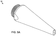
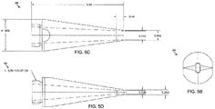
- FIGS. 4A-C show a die 60 and FIGS. 5A-D show a tip 64 for use in this process. In FIGS. 5C and 5D , internal surfaces of the tip 64 are marked with dashed lines.
- FIGS. 6A-B show a pressure tip and die assembly 68, with portions of the die 60 removed. One embodiment of approximate dimensions of the die 60 and the tip 64 are shown in inches.
- the pressure tip and die assembly 68 can include the tip 64 and the die 60.
- the pressure tip and die assembly 68 can include the tip 64 inserted into a die-tip cavity 72 of the die 60.
- the pressure tip and die assembly 68 can be used with a screw manufacturing machine (not shown) in order to form the final jacket 36 to the braid 34.
- the adhesion of the final jacket 36 to the braid 34 can be improved by increasing melt pressure in the die-tip cavity 72 of the pressure tip and die assembly 68.
- One method for increasing the melt pressure in the die-tip cavity 72 is to push the tip 64 further into the die-tip cavity 72 towards a die exit 74.
- the braid 34 will be forced into the final jacket 36 and will further penetrate the final jacket 36, increasing adhesion of the jacket 36 to the braid 34.
- the braid 34 is forced into the final jacket 36 too much, the final jacket 36 may not be thick enough to pass certain mechanical tests such as impact resistance, so the distance the tip 64 is inserted into the die 60 toward the die exit 74 can be limited accordingly.
- the final jacket 36 can be made using an extruder with pressure tooling such as the pressure tip and die assembly 68 in order to force the molten polymer pumped by the extruder to wrap the surface of the braid 34 when the final jacket 36 is inside the flow channel between a die (i.e., the die 60) and a tip (e.g., the tip 64) of the extruder.
- the final jacket 36 can be made using vacuum extrusion. Extrusion using pressure tooling may be more desirable than vacuum extrusion because the LSZH materials used to form the final jacket 36 are generally highly filled and viscous, which can make it more difficult to conform the final jacket 36 to the braid 34 using vacuum extrusion for tube-down extrusion.
- the final jacket 36 can be made using an extruder with post extrusion compression or forming to press the final jacket 36 into the braid 34.
- the post extrusion compression can include the application of multiple rollers to the somewhat pliable final jacket 36 in order to press the final jacket 36 into the braid 34.
- Forming the final jacket 36 to the braid using processes including using an extruder with pressure tooling, using vacuum extrusion, or using an extruder with post extrusion compression or forming as described above may cause the jacket 36 to be harder to strip, and therefore increase the difficulty of installing the cable 24, 26.
- the additional flammability protection afforded by the forming of the jacket 36 to the braid 34 may be desirable even with the potential difficulty in installing the heating cable 24, 26.
- the final jacket 36 can thermally contact multiple overlapping portions of the braid 34. More specifically, the final jacket 36 can be in thermal contact with the first portion 34A and the second portion 34B of the braid. Even though the first portion 34A is arranged below the second portion 34B, the final jacket 36 can thermally contact a sufficient portion of the braid in order to achieve the mated connection as a result of an appropriate forming process such as pressure extrusion, vacuum extrusion, or extrusion with post extrusion compression or forming, such as applying multiple rollers to the final jacket 36 after extrusion.
- an appropriate forming process such as pressure extrusion, vacuum extrusion, or extrusion with post extrusion compression or forming, such as applying multiple rollers to the final jacket 36 after extrusion.
- the final jacket 36 can be configured to conduct an approximately equal amount of heat to the first portion 34A and the second portion 34B, despite the different radial positions of the first portion 34A and the second portion 34B. In some embodiments, the amount of heat conducted to the first portion 34A may be within about twenty percent of the amount heat conducted to the second portion 34B.
- FIGS. 7 and 8 illustrate cables subjected to a flame test.
- the cables were made with an extruder and semi-pressure tooling.
- the cables were made with an extruder and pressure tooling to form the final jackets to the braids in order to create a mated connection between the final jackets and the braid. All cables were made with LSZH materials. All cables were subjected to a vertical flame test with five applications of flame for a duration of fifteen seconds. Between each application of flame, the flame is removed and the cables are allowed to cool down for fifteen seconds. Tables 1 and 2 below provide the results of the tests of the cables made with semi-pressure tooling and pressure tooling.
- the after burn time is the duration of time the cable was on fire after the flame was removed after each flame application.
- the cables made with semi-pressure tooling were ignited on the first or second flame application, forming a char layer, while the cables made with pressure tooling were not ignited until the third or fourth flame application.
- the final jackets of the cables made with semi-pressure tooling expanded during the first flame application, which made the final jackets lose contact with the braids, which prevented the braids from acting as a heat sink. Additionally, the final jackets of the cables made with semi-pressure tooling were burned through by the end of testing, exposing the braid and other layers. As shown in FIG. 7 , each cable made with semi-pressure tooling had a braid 80, 82, 84 exposed as a result of the flame applications.
- the final jackets of the cables made with pressure tooling did not freely expand, and remained intact throughout the testing.
- the cables made with pressure tooling provided superior flammability protection as compared to the cables made with semi-pressure tooling. While the final jackets of the cables were constructed with LSZH materials, other types of flame retarded jackets than LSZH may benefit from being formed to the braid in order to create the mated connection between the final jacket and the braid.
- FIG. 9 illustrate a manufacturing process 100 for producing a heating cable having increased flammability protection according to some embodiments of the invention.
- the heating cable can be the cable 24 or the cable 26 of FIGS. 2 and 3 .
- the manufacturing process 100 can be used to produce a cable having a final jacket, for example the final jacket 36, formed to a braid, for example the braid 34, in order to create a mated connection between the final jacket 36 and the braid 34 in order to increase the flammability protection of the heating cable.
- the manufacturing process 100 can receive (at 104) a partially finished heating cable including parallel conductor wires 28, the core 30, the primary jacket 32, and the braid 34.
- the partially finished heating cable may include the optional barrier layer 38.
- the manufacturing process 100 can produce and form (at 108) the final jacket 36 to the braid 34 to create the mated connection between the final jacket 36 and the braid 34.
- the final jacket can be formed using LSZH materials that may include a polyolefin flame-retarded with inorganic hydrated mineral fillers.
- the forming of the final jacket 36 to the braid 34 to create the mated connection between the final jacket 36 and the braid 34 can include forming the final jacket 36 to the braid 34 using an extruder with pressure tooling.
- the final jacket 36 can be made using an extruder with pressure tooling in order to force the molten polymer pumped by the extruder to wrap the surface of the braid 34 when the final jacket 36 is inside the flow channel between a die and a tip of the extruder.
- the extruder with pressure tooling can include the pressure tip and die assembly 68.
- the forming of the final jacket 36 to the braid 34 to create the mated connection between the final jacket 36 and the braid 34 can include producing and forming the final jacket 36 to the braid 34 using vacuum extrusion.
- the forming of the final jacket 36 to the braid 34 to create the mated connection between the final jacket 36 and the braid 34 can include producing and forming the final jacket 36 to the braid 34 using an extruder with post extrusion compression or forming to press the final jacket 36 into the braid 34.
- the post extrusion compression or forming can include applying multiple rollers to the final jacket 36 after extrusion while the final jacket 36 is still somewhat pliable.
- the heating cable e.g., the cable 24 or the cable 26 described above
- the manufacturing process 100 can output (at 112) a finished heating cable including the parallel conductor wires 28, the core 30, the primary jacket 32, the braid 34, and the final jacket 36 formed to the braid 34 and having a mated connection with the braid 34.
- the finished heating cable can have increased flammability protection as a result of mated connection by causing the braid 34 to act as a heat sink for the final jacket 36 and help to prevent the final jacket 36 from expanding away from the braid 34 during a flame application.
- the finished heating cable can optionally include the barrier layer 38.
- LSZH self-regulating heating cables 24, 26 described above are monolithic self-regulating heating cables (that is, having a solid conductive core 30), the principles of the invention may be used with fiber-wrap self-regulating heating cables.
Landscapes
- Insulated Conductors (AREA)
Applications Claiming Priority (1)
| Application Number | Priority Date | Filing Date | Title |
|---|---|---|---|
| US201862776592P | 2018-12-07 | 2018-12-07 |
Publications (1)
| Publication Number | Publication Date |
|---|---|
| EP3664575A1 true EP3664575A1 (fr) | 2020-06-10 |
Family
ID=68847945
Family Applications (1)
| Application Number | Title | Priority Date | Filing Date |
|---|---|---|---|
| EP19214628.0A Withdrawn EP3664575A1 (fr) | 2018-12-07 | 2019-12-09 | Amélioration de l'inflammabilité d'un câble chauffant |
Country Status (2)
| Country | Link |
|---|---|
| US (2) | US11778700B2 (fr) |
| EP (1) | EP3664575A1 (fr) |
Cited By (1)
| Publication number | Priority date | Publication date | Assignee | Title |
|---|---|---|---|---|
| US20230284344A1 (en) * | 2017-02-01 | 2023-09-07 | Nvent Services Gmbh | Low Smoke, Zero Halogen Self-Regulating Heating Cable |
Families Citing this family (1)
| Publication number | Priority date | Publication date | Assignee | Title |
|---|---|---|---|---|
| RU2735946C1 (ru) * | 2020-03-26 | 2020-11-11 | Михаил Леонидович Струпинский | Нагревательное устройство |
Citations (3)
| Publication number | Priority date | Publication date | Assignee | Title |
|---|---|---|---|---|
| EP0536165A1 (fr) * | 1990-05-07 | 1993-04-14 | Raychem Corp | Dispositif de chauffage allonge a resistance electrique. |
| WO2001033908A1 (fr) * | 1999-11-03 | 2001-05-10 | Tyco Electronics Corporation | Cable electrique a plan de terre polymere sans tresse, fournissant une detection des defauts |
| US20180220495A1 (en) * | 2017-02-01 | 2018-08-02 | Pentair Flow Services Ag | Low Smoke, Zero Halogen Self-Regulating Heating Cable |
Family Cites Families (29)
| Publication number | Priority date | Publication date | Assignee | Title |
|---|---|---|---|---|
| US4271350A (en) | 1980-05-19 | 1981-06-02 | Sunbeam Corporation | Blanket wire utilizing positive temperature coefficient resistance heater |
| US4309596A (en) | 1980-06-24 | 1982-01-05 | Sunbeam Corporation | Flexible self-limiting heating cable |
| GB2294801B (en) | 1994-11-07 | 1999-04-21 | Bka | Improvements in and relating to electrical cables |
| US6563990B1 (en) | 1998-06-22 | 2003-05-13 | Corning Cable Systems, Llc | Self-supporting cables and an apparatus and methods for making the same |
| US6542674B1 (en) | 2000-08-25 | 2003-04-01 | Corning Cable Systems Llc | Fiber optic cables with strength members |
| US20040096166A1 (en) | 2002-11-15 | 2004-05-20 | Alcatel | Jacket materials and cable design for duct application |
| CA2627269C (fr) | 2005-10-27 | 2014-05-06 | Prysmian Cavi E Sistemi Energia S.R.L. | Cable autoextinguible a faible fumee et composition ignifugeante comprenant de l'hydroxyde de magnesium naturel |
| US8422843B2 (en) | 2008-03-28 | 2013-04-16 | Adc Telecommunications, Inc. | Multi-fiber fiber optic cable |
| BR112014002385B1 (pt) | 2011-08-04 | 2020-03-10 | Prysmian Telecom Cables And Systems Uk Limited | Cabo de telecomunicação, método para instalação de um cabo de telecomunicação, e, processo para fabricação de um cabo de telecomunicação |
| MX348660B (es) | 2011-11-04 | 2017-05-29 | Servicios Condumex Sa | Composicion para aislamientos termoplasticos libres de halogenos, retardantes a la flama, con baja emision de humos obscuros y buenas propiedades electricas en agua. |
| US20140037956A1 (en) * | 2012-08-01 | 2014-02-06 | Umesh Kumar Sopory | High voltage high temperature heater cables, connectors, and insulations |
| CN103440921B (zh) | 2013-08-29 | 2015-09-23 | 宁夏瑞银有色金属科技有限公司 | 低烟无卤高阻燃电力电缆 |
| US9378868B2 (en) | 2013-09-05 | 2016-06-28 | Equistar Chemicals, Lp | Low-smoke, non-halogenated flame retardant composition and related power cable jackets |
| US10809475B2 (en) | 2014-03-18 | 2020-10-20 | Corning Optical Communications LLC | Jacket for a fiber optic cable |
| CN103985472B (zh) | 2014-04-11 | 2017-03-08 | 安徽省赛华电缆有限公司 | 骨架连接的扁形电力电缆 |
| US9482835B2 (en) | 2014-06-27 | 2016-11-01 | Corning Optical Communications LLC | Extreme environment optical fiber cable with crack-resistant layer |
| US20160018612A1 (en) | 2014-07-15 | 2016-01-21 | Ofs Fitel, Llc | Systems and methods for cable distribution |
| CN204305377U (zh) | 2014-09-05 | 2015-04-29 | 天津三佳线缆有限公司 | 一种发热电缆 |
| WO2016075120A1 (fr) | 2014-11-10 | 2016-05-19 | Tyco Electronics Uk Infrastructure Limited | Câble optique avec éléments ignifuges résistants à la traction |
| CN104681159A (zh) | 2015-03-18 | 2015-06-03 | 中天科技装备电缆有限公司 | 一种轻型柔软低烟无卤耐火低压船用电缆及其工艺流程 |
| PL3702821T3 (pl) | 2015-08-18 | 2023-09-11 | Corning Optical Communications LLC | Wiązka światłowodowa |
| ES2945057T3 (es) | 2015-11-30 | 2023-06-28 | Corning Optical Communications LLC | Recubrimiento coextruido para cables de fibra óptica retardantes de llama |
| US9696510B1 (en) | 2015-12-30 | 2017-07-04 | Hitachi Cable America Inc. | Small form factor flame resistant low smoke halogen free fiber optic cable |
| CN106128598B (zh) * | 2016-07-07 | 2018-04-27 | 扬州曙光电缆股份有限公司 | 一种轨道交通车辆用环保电缆 |
| US10283239B2 (en) | 2016-12-20 | 2019-05-07 | American Fire Wire, Inc. | Fire resistant coaxial cable and manufacturing technique |
| US9773585B1 (en) | 2016-12-20 | 2017-09-26 | American Fire Wire, Inc. | Fire resistant coaxial cable |
| US10845558B2 (en) | 2017-02-07 | 2020-11-24 | Ofs Fitel, Llc | High count optical fiber cable configuration |
| CN110690008A (zh) * | 2019-10-15 | 2020-01-14 | 江苏上上电缆集团有限公司 | 一种核电站用耐辐射的小截面高压直流电缆及其制造方法 |
| CN217767940U (zh) * | 2022-05-26 | 2022-11-08 | 江苏上上电缆集团有限公司 | 额定电压35kV地铁用低烟无卤B1级阻燃电力电缆 |
-
2019
- 2019-12-09 US US16/708,173 patent/US11778700B2/en active Active
- 2019-12-09 EP EP19214628.0A patent/EP3664575A1/fr not_active Withdrawn
-
2023
- 2023-10-03 US US18/480,369 patent/US20240032157A1/en active Pending
Patent Citations (3)
| Publication number | Priority date | Publication date | Assignee | Title |
|---|---|---|---|---|
| EP0536165A1 (fr) * | 1990-05-07 | 1993-04-14 | Raychem Corp | Dispositif de chauffage allonge a resistance electrique. |
| WO2001033908A1 (fr) * | 1999-11-03 | 2001-05-10 | Tyco Electronics Corporation | Cable electrique a plan de terre polymere sans tresse, fournissant une detection des defauts |
| US20180220495A1 (en) * | 2017-02-01 | 2018-08-02 | Pentair Flow Services Ag | Low Smoke, Zero Halogen Self-Regulating Heating Cable |
Cited By (2)
| Publication number | Priority date | Publication date | Assignee | Title |
|---|---|---|---|---|
| US20230284344A1 (en) * | 2017-02-01 | 2023-09-07 | Nvent Services Gmbh | Low Smoke, Zero Halogen Self-Regulating Heating Cable |
| US11956865B2 (en) * | 2017-02-01 | 2024-04-09 | Nvent Services Gmbh | Low smoke, zero halogen self-regulating heating cable |
Also Published As
| Publication number | Publication date |
|---|---|
| US20200187308A1 (en) | 2020-06-11 |
| US11778700B2 (en) | 2023-10-03 |
| US20240032157A1 (en) | 2024-01-25 |
Similar Documents
| Publication | Publication Date | Title |
|---|---|---|
| US20240032157A1 (en) | Improving Flammability of Heating Cable | |
| US11956865B2 (en) | Low smoke, zero halogen self-regulating heating cable | |
| JP6621168B2 (ja) | ノンハロゲン難燃性樹脂組成物を用いた送電ケーブル | |
| CN108369841B (zh) | 耐火电缆 | |
| US20090078446A1 (en) | Fire-resistant safety cable provided with a single insulating covering | |
| JP2019011448A (ja) | ケーブル | |
| WO2014010509A1 (fr) | Composition de résine ignifuge résistante à la chaleur, fil électrique isolé, et tube | |
| US20170062092A1 (en) | Insulated electric wire and cable using halogen-free flame-retardant resin composition | |
| WO2004025679A1 (fr) | Fusible thermique a noyau et a gaine | |
| JP6410184B2 (ja) | 多層熱回復物品及び接続構造 | |
| US10692629B2 (en) | Fire resistant cable | |
| JP6795481B2 (ja) | 絶縁電線 | |
| US20240106221A1 (en) | Heat shrinkable tube, heat shrinkable coupling component, method of manufacturing heat shrinkable tube, and method of manufacturing heat shrinkable coupling component | |
| JP6388216B2 (ja) | 絶縁電線及びケーブル | |
| RU2808049C1 (ru) | Способ изготовления силового кабеля и кабель, изготавливаемый данным способом | |
| JP7380494B2 (ja) | 絶縁電線およびケーブル | |
| CN1972536A (zh) | 应用在低温级自控温加热电缆中的阻燃型发热元件 | |
| JP2017212156A (ja) | ケーブル |
Legal Events
| Date | Code | Title | Description |
|---|---|---|---|
| PUAI | Public reference made under article 153(3) epc to a published international application that has entered the european phase |
Free format text: ORIGINAL CODE: 0009012 |
|
| STAA | Information on the status of an ep patent application or granted ep patent |
Free format text: STATUS: THE APPLICATION HAS BEEN PUBLISHED |
|
| AK | Designated contracting states |
Kind code of ref document: A1 Designated state(s): AL AT BE BG CH CY CZ DE DK EE ES FI FR GB GR HR HU IE IS IT LI LT LU LV MC MK MT NL NO PL PT RO RS SE SI SK SM TR |
|
| AX | Request for extension of the european patent |
Extension state: BA ME |
|
| STAA | Information on the status of an ep patent application or granted ep patent |
Free format text: STATUS: THE APPLICATION IS DEEMED TO BE WITHDRAWN |
|
| 18D | Application deemed to be withdrawn |
Effective date: 20201211 |