EP3664527B1 - Procédé de réglage de temporisation de liaison montante dans un système de communication sans fil et dispositif associé - Google Patents
Procédé de réglage de temporisation de liaison montante dans un système de communication sans fil et dispositif associé Download PDFInfo
- Publication number
- EP3664527B1 EP3664527B1 EP18843736.2A EP18843736A EP3664527B1 EP 3664527 B1 EP3664527 B1 EP 3664527B1 EP 18843736 A EP18843736 A EP 18843736A EP 3664527 B1 EP3664527 B1 EP 3664527B1
- Authority
- EP
- European Patent Office
- Prior art keywords
- command
- cell
- random access
- timing
- base station
- Prior art date
- Legal status (The legal status is an assumption and is not a legal conclusion. Google has not performed a legal analysis and makes no representation as to the accuracy of the status listed.)
- Active
Links
- 238000000034 method Methods 0.000 title claims description 227
- 238000004891 communication Methods 0.000 title claims description 41
- 230000005540 biological transmission Effects 0.000 claims description 65
- 230000004044 response Effects 0.000 claims description 43
- 210000004027 cell Anatomy 0.000 description 215
- 230000002776 aggregation Effects 0.000 description 45
- 238000004220 aggregation Methods 0.000 description 45
- 210000004457 myocytus nodalis Anatomy 0.000 description 25
- 230000008569 process Effects 0.000 description 21
- 238000001994 activation Methods 0.000 description 17
- 239000000969 carrier Substances 0.000 description 17
- 230000004913 activation Effects 0.000 description 16
- 230000009849 deactivation Effects 0.000 description 12
- 238000010586 diagram Methods 0.000 description 12
- 230000006870 function Effects 0.000 description 11
- 230000015654 memory Effects 0.000 description 11
- 230000007420 reactivation Effects 0.000 description 8
- 239000000872 buffer Substances 0.000 description 7
- 238000010295 mobile communication Methods 0.000 description 6
- 230000008859 change Effects 0.000 description 5
- 125000004122 cyclic group Chemical group 0.000 description 5
- 238000005516 engineering process Methods 0.000 description 5
- 238000012544 monitoring process Methods 0.000 description 5
- 230000008901 benefit Effects 0.000 description 4
- 230000004048 modification Effects 0.000 description 4
- 238000012986 modification Methods 0.000 description 4
- 238000002360 preparation method Methods 0.000 description 4
- CSRZQMIRAZTJOY-UHFFFAOYSA-N trimethylsilyl iodide Substances C[Si](C)(C)I CSRZQMIRAZTJOY-UHFFFAOYSA-N 0.000 description 4
- 230000002441 reversible effect Effects 0.000 description 3
- 230000001174 ascending effect Effects 0.000 description 2
- 230000001419 dependent effect Effects 0.000 description 2
- 238000007726 management method Methods 0.000 description 2
- 238000013507 mapping Methods 0.000 description 2
- 238000012545 processing Methods 0.000 description 2
- 230000009467 reduction Effects 0.000 description 2
- 230000001360 synchronised effect Effects 0.000 description 2
- 101000741965 Homo sapiens Inactive tyrosine-protein kinase PRAG1 Proteins 0.000 description 1
- 102100038659 Inactive tyrosine-protein kinase PRAG1 Human genes 0.000 description 1
- 101100465000 Mus musculus Prag1 gene Proteins 0.000 description 1
- 230000004308 accommodation Effects 0.000 description 1
- 230000003213 activating effect Effects 0.000 description 1
- 238000003491 array Methods 0.000 description 1
- 238000012937 correction Methods 0.000 description 1
- 230000003111 delayed effect Effects 0.000 description 1
- 238000011161 development Methods 0.000 description 1
- 230000009977 dual effect Effects 0.000 description 1
- 230000007774 longterm Effects 0.000 description 1
- 239000011159 matrix material Substances 0.000 description 1
- 230000006855 networking Effects 0.000 description 1
- 238000011084 recovery Methods 0.000 description 1
- 238000013468 resource allocation Methods 0.000 description 1
- 230000011664 signaling Effects 0.000 description 1
- 238000001228 spectrum Methods 0.000 description 1
- 239000013589 supplement Substances 0.000 description 1
- 238000012546 transfer Methods 0.000 description 1
- 238000012384 transportation and delivery Methods 0.000 description 1
Images


Classifications
-
- H—ELECTRICITY
- H04—ELECTRIC COMMUNICATION TECHNIQUE
- H04W—WIRELESS COMMUNICATION NETWORKS
- H04W56/00—Synchronisation arrangements
- H04W56/004—Synchronisation arrangements compensating for timing error of reception due to propagation delay
- H04W56/005—Synchronisation arrangements compensating for timing error of reception due to propagation delay compensating for timing error by adjustment in the receiver
-
- H—ELECTRICITY
- H04—ELECTRIC COMMUNICATION TECHNIQUE
- H04W—WIRELESS COMMUNICATION NETWORKS
- H04W56/00—Synchronisation arrangements
- H04W56/004—Synchronisation arrangements compensating for timing error of reception due to propagation delay
- H04W56/0045—Synchronisation arrangements compensating for timing error of reception due to propagation delay compensating for timing error by altering transmission time
-
- H—ELECTRICITY
- H04—ELECTRIC COMMUNICATION TECHNIQUE
- H04L—TRANSMISSION OF DIGITAL INFORMATION, e.g. TELEGRAPHIC COMMUNICATION
- H04L27/00—Modulated-carrier systems
- H04L27/26—Systems using multi-frequency codes
- H04L27/2601—Multicarrier modulation systems
- H04L27/2602—Signal structure
- H04L27/26025—Numerology, i.e. varying one or more of symbol duration, subcarrier spacing, Fourier transform size, sampling rate or down-clocking
-
- H—ELECTRICITY
- H04—ELECTRIC COMMUNICATION TECHNIQUE
- H04L—TRANSMISSION OF DIGITAL INFORMATION, e.g. TELEGRAPHIC COMMUNICATION
- H04L27/00—Modulated-carrier systems
- H04L27/26—Systems using multi-frequency codes
- H04L27/2601—Multicarrier modulation systems
- H04L27/2602—Signal structure
- H04L27/2605—Symbol extensions, e.g. Zero Tail, Unique Word [UW]
- H04L27/2607—Cyclic extensions
-
- H—ELECTRICITY
- H04—ELECTRIC COMMUNICATION TECHNIQUE
- H04W—WIRELESS COMMUNICATION NETWORKS
- H04W56/00—Synchronisation arrangements
- H04W56/001—Synchronization between nodes
-
- H—ELECTRICITY
- H04—ELECTRIC COMMUNICATION TECHNIQUE
- H04W—WIRELESS COMMUNICATION NETWORKS
- H04W72/00—Local resource management
- H04W72/04—Wireless resource allocation
- H04W72/044—Wireless resource allocation based on the type of the allocated resource
- H04W72/0446—Resources in time domain, e.g. slots or frames
-
- H—ELECTRICITY
- H04—ELECTRIC COMMUNICATION TECHNIQUE
- H04W—WIRELESS COMMUNICATION NETWORKS
- H04W72/00—Local resource management
- H04W72/04—Wireless resource allocation
- H04W72/044—Wireless resource allocation based on the type of the allocated resource
- H04W72/0453—Resources in frequency domain, e.g. a carrier in FDMA
-
- H—ELECTRICITY
- H04—ELECTRIC COMMUNICATION TECHNIQUE
- H04W—WIRELESS COMMUNICATION NETWORKS
- H04W74/00—Wireless channel access, e.g. scheduled or random access
- H04W74/002—Transmission of channel access control information
-
- H—ELECTRICITY
- H04—ELECTRIC COMMUNICATION TECHNIQUE
- H04W—WIRELESS COMMUNICATION NETWORKS
- H04W74/00—Wireless channel access, e.g. scheduled or random access
- H04W74/08—Non-scheduled or contention based access, e.g. random access, ALOHA, CSMA [Carrier Sense Multiple Access]
- H04W74/0833—Non-scheduled or contention based access, e.g. random access, ALOHA, CSMA [Carrier Sense Multiple Access] using a random access procedure
- H04W74/0841—Non-scheduled or contention based access, e.g. random access, ALOHA, CSMA [Carrier Sense Multiple Access] using a random access procedure with collision treatment
-
- H—ELECTRICITY
- H04—ELECTRIC COMMUNICATION TECHNIQUE
- H04W—WIRELESS COMMUNICATION NETWORKS
- H04W76/00—Connection management
- H04W76/20—Manipulation of established connections
- H04W76/27—Transitions between radio resource control [RRC] states
-
- H—ELECTRICITY
- H04—ELECTRIC COMMUNICATION TECHNIQUE
- H04L—TRANSMISSION OF DIGITAL INFORMATION, e.g. TELEGRAPHIC COMMUNICATION
- H04L5/00—Arrangements affording multiple use of the transmission path
- H04L5/0001—Arrangements for dividing the transmission path
- H04L5/0003—Two-dimensional division
- H04L5/0005—Time-frequency
- H04L5/0007—Time-frequency the frequencies being orthogonal, e.g. OFDM(A), DMT
- H04L5/001—Time-frequency the frequencies being orthogonal, e.g. OFDM(A), DMT the frequencies being arranged in component carriers
-
- H—ELECTRICITY
- H04—ELECTRIC COMMUNICATION TECHNIQUE
- H04L—TRANSMISSION OF DIGITAL INFORMATION, e.g. TELEGRAPHIC COMMUNICATION
- H04L5/00—Arrangements affording multiple use of the transmission path
- H04L5/003—Arrangements for allocating sub-channels of the transmission path
- H04L5/0053—Allocation of signaling, i.e. of overhead other than pilot signals
-
- H—ELECTRICITY
- H04—ELECTRIC COMMUNICATION TECHNIQUE
- H04W—WIRELESS COMMUNICATION NETWORKS
- H04W74/00—Wireless channel access, e.g. scheduled or random access
- H04W74/002—Transmission of channel access control information
- H04W74/006—Transmission of channel access control information in the downlink, i.e. towards the terminal
-
- H—ELECTRICITY
- H04—ELECTRIC COMMUNICATION TECHNIQUE
- H04W—WIRELESS COMMUNICATION NETWORKS
- H04W80/00—Wireless network protocols or protocol adaptations to wireless operation
- H04W80/02—Data link layer protocols
-
- Y—GENERAL TAGGING OF NEW TECHNOLOGICAL DEVELOPMENTS; GENERAL TAGGING OF CROSS-SECTIONAL TECHNOLOGIES SPANNING OVER SEVERAL SECTIONS OF THE IPC; TECHNICAL SUBJECTS COVERED BY FORMER USPC CROSS-REFERENCE ART COLLECTIONS [XRACs] AND DIGESTS
- Y02—TECHNOLOGIES OR APPLICATIONS FOR MITIGATION OR ADAPTATION AGAINST CLIMATE CHANGE
- Y02D—CLIMATE CHANGE MITIGATION TECHNOLOGIES IN INFORMATION AND COMMUNICATION TECHNOLOGIES [ICT], I.E. INFORMATION AND COMMUNICATION TECHNOLOGIES AIMING AT THE REDUCTION OF THEIR OWN ENERGY USE
- Y02D30/00—Reducing energy consumption in communication networks
- Y02D30/70—Reducing energy consumption in communication networks in wireless communication networks
Definitions
- the present disclosure relates to a wireless communication system and, more particularly, to a method of adjusting uplink timing and an apparatus supporting the same.
- Mobile communication systems have been generally developed to provide voice services while guaranteeing user mobility. Such mobile communication systems have gradually expanded their coverage from voice services through data services up to high-speed data services. However, as current mobile communication systems suffer resource shortages and users demand even higher-speed services, development of more advanced mobile communication systems is needed.
- the requirements of the next-generation mobile communication system may include supporting huge data traffic, a remarkable increase in the transfer rate of each user, the accommodation of a significantly increased number of connection devices, very low end-to-end latency, and high energy efficiency.
- various techniques such as small cell enhancement, dual connectivity, massive multiple input multiple output (MIMO), in-band full duplex, non-orthogonal multiple access (NOMA), supporting super-wide band, and device networking, have been researched.
- This disclosure proposes a method of adjusting uplink timing in a wireless communication system and an apparatus therefor.
- a base station has the meaning of a terminal node of a network over which the base station directly communicates with a terminal.
- a specific operation that is described to be performed by a base station may be performed by an upper node of the base station according to circumstances. That is, it is evident that in a network including a plurality of network nodes including a base station, various operations performed for communication with a terminal may be performed by the base station or other network nodes other than the base station.
- the base station may be substituted with another term, such as a fixed station, a Node B, an eNB (evolved-NodeB), a base transceiver system (BTS), an access point (AP), or next generation NB (general NB, gNodeB, gNB).
- the terminal may be fixed or may have mobility and may be substituted with another term, such as user equipment (UE), a mobile station (MS), a user terminal (UT), a mobile subscriber station (MSS), a subscriber station (SS), an advanced mobile station (AMS), a wireless terminal (WT), a machine-type communication (MTC) device, a machine-to-Machine (M2M) device, or a device-to-device (D2D) device.
- UE user equipment
- MS mobile station
- UT user terminal
- MSS mobile subscriber station
- SS subscriber station
- AMS advanced mobile station
- WT wireless terminal
- MTC machine-type communication
- M2M machine-to-Machine
- D2D device-to-device
- downlink means communication from a base station to UE
- uplink means communication from UE to a base station.
- a transmitter may be part of a base station, and a receiver may be part of UE.
- a transmitter may be part of UE, and a receiver may be part of a base station.
- CDMA code division multiple access
- FDMA frequency division multiple access
- TDMA time division multiple access
- OFDMA orthogonal frequency division multiple access
- SC-FDMA single carrier frequency division multiple access
- NOMA non-orthogonal multiple access
- CDMA may be implemented using a radio technology, such as universal terrestrial radio access (UTRA) or CDMA2000.
- TDMA may be implemented using a radio technology, such as global system for mobile communications (GSM)/general packet radio service (GPRS)/enhanced data rates for GSM evolution (EDGE).
- GSM global system for mobile communications
- GPRS general packet radio service
- EDGE enhanced data rates for GSM evolution
- OFDMA may be implemented using a radio technology, such as Institute of electrical and electronics engineers (IEEE) 802.11 (Wi-Fi), IEEE 802.16 (WiMAX), IEEE 802.20, or evolved UTRA (E-UTRA).
- UTRA is part of a universal mobile telecommunications system (UMTS).
- 3rd generation partnership project (3GPP) Long term evolution (LTE) is part of an evolved UMTS (E-UMTS) using evolved UMTS terrestrial radio access (E-UTRA), and it adopts OFDMA in downlink and adopts SC-FDMA in uplink.
- LTE-advanced (LTE-A) is the evolution of 3GPP LTE.
- a 5G new radio defines an enhanced mobile broadband (eMBB), massive machine type communications (mMTC), ultra-reliable and low latency communications (URLLC), and vehicle-to-everything (V2X) based on a usage scenario.
- eMBB enhanced mobile broadband
- mMTC massive machine type communications
- URLLC ultra-reliable and low latency communications
- V2X vehicle-to-everything
- the 5G NR standard is divided into standalone (SA) and non-standalone (NSA) based on co-existence between the NR system and the LTE system.
- the 5G NR supports various subcarrier spacings, and supports CP-OFDM in the downlink and supports CP-OFDM and DFT-s-OFDM (SC-OFDM) in the uplink.
- Embodiments of the present disclosure may be supported by the standard documents disclosed in at least one of IEEE 802, 3GPP, and 3GPP2, that is, radio access systems. That is, steps or portions that belong to the embodiments of the present disclosure and that are not described may be supported by the documents. Furthermore, all terms disclosed in this document may be described by the standard documents.
- 3GPP LTE/LTE-A/New RAT is chiefly described, but the technical characteristics of the present disclosure are not limited thereto.
- a network function is a logical node in a network infra that has a well-defined external interface and a well-defined functional operation.
- FIG. 1 is a diagram illustrating an example of an overall structure of a new radio (NR) system to which a method proposed by the present disclosure may be implemented.
- NR new radio
- an NG-RAN is composed of gNBs that provide an NG-RA user plane (new AS sublayer/PDCP/RLC/MAC/PHY) and a control plane (RRC) protocol terminal for a UE (User Equipment).
- NG-RA user plane new AS sublayer/PDCP/RLC/MAC/PHY
- RRC control plane
- the gNBs are connected to each other via an Xn interface.
- the gNBs are also connected to an NGC via an NG interface.
- the gNBs are connected to a Access and Mobility Management Function (AMF) via an N2 interface and a User Plane Function (UPF) via an N3 interface.
- AMF Access and Mobility Management Function
- UPF User Plane Function
- multiple numerologies may be supported.
- the numerologies may be defined by subcarrier spacing and a CP (Cyclic Prefix) overhead. Spacing between the plurality of subcarriers may be derived by scaling basic subcarrier spacing into an integer N (or ⁇ ).
- N or ⁇
- a numerology to be used may be selected independent of a frequency band.
- OFDM Orthogonal Frequency Division Multiplexing
- a plurality of OFDM numerologies supported in the NR system may be defined as in Table 1.
- ⁇ f max 480 ⁇ 10 3
- N f 4096.
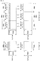
- FIG. 2 illustrates a relationship between a UL frame and a DL frame in a wireless communication system to which a method proposed by the present disclosure may be implemented.
- slots are numbered in ascending order of n s ⁇ ⁇ 0 , ... , N subframe slots , ⁇ ⁇ 1 in a subframe, and in ascending order of n s , f ⁇ ⁇ 0 , ... , N frame slots , ⁇ ⁇ 1 in a radio frame.
- One slot is composed of continuous OFDM symbols of N symb ⁇ , and N symb ⁇ is determined depending on a numerology in use and slot configuration.
- the start of slots n s ⁇ in a subframe is temporally aligned with the start of OFDM symbols n s ⁇ N symb ⁇ in the same subframe.
- Not all UEs are able to transmit and receive at the same time, and this means that not all OFDM symbols in a DL slot or an UL slot are available to be used.
- Table 2 shows the number of OFDM symbols per slot for a normal CP in the numerology ⁇
- Table 3 shows the number of OFDM symbols per slot for an extended CP in the numerology ⁇ .
- [Table 2] ⁇ Slot configuration 0 1 N symb ⁇ N frame slots , ⁇ N subframe slots , ⁇ N symb ⁇ N frame slots , ⁇ N subframe slots , ⁇ 0 14 10 1 7 20 2 1 14 20 2 7 40 4 2 14 40 4 7 80 8 3 14 80 8 - - - 4 14 160 16 - - - 5 14 320 32 - - - [Table 3] ⁇ Slot configuration 0 1 N symb ⁇ N frame slots , ⁇ N subframe slots , ⁇ N symb ⁇ N frame slots , ⁇ N subframe slots , ⁇ 0 12 10 1 6 20 2 1 12 20 2 6 40 4 2 12 40 4 6 80 8 3 12 80 8 - - - 4 12 160 16
- an antenna port a resource grid, a resource element, a resource block, a carrier part, etc. may be considered.
- the antenna port is defined such that a channel over which a symbol on one antenna port is transmitted can be inferred from another channel over which a symbol on the same antenna port is transmitted.
- the two antenna ports may be in a QC/QCL (quasi co-located or quasi co-location) relationship.
- the large-scale properties may include at least one of delay spread, Doppler spread, Doppler shift, average gain, and average delay.
- FIG. 3 illustrates an example of a resource grid supported in a wireless communication system to which a method proposed by the present disclosure may be implemented.
- a resource grid is composed of N RB ⁇ N sc RB subcarriers in a frequency domain, each subframe composed of 14 ⁇ 2 ⁇ OFDM symbols, but the present disclosure is not limited thereto.
- a transmitted signal is described by one or more resource grids, composed of N RB ⁇ N sc RB subcarriers, and 2 ⁇ N symb ⁇ OFDM symbols
- N RB ⁇ ⁇ N RB max , ⁇ indicates the maximum transmission bandwidth, and it may change not just between numerologies, but between UL and DL.
- one resource grid may be configured for the numerology ⁇ and an antenna port p.
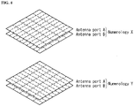
- FIG. 4 illustrates examples of resource grids for each antenna port and numerology to which a method proposed in this disclosure may be applied.
- Each element of the resource grid for the numerology ⁇ and the antenna port p is indicated as a resource element, and may be uniquely identified by an index pair ( k , l ).
- the index pair (k, l ) is used.
- l 0 , ... , N symb ⁇ ⁇ 1 .
- the resource element (k, l ) for the numerology ⁇ and the antenna port p corresponds to a complex value a k , l ⁇ p ⁇ .
- the indexes p and ⁇ may be dropped and thereby the complex value may become a k , l ⁇ p or a k, l .
- physical resource blocks may be numbered from 0 to N RB ⁇ ⁇ 1 .
- n PRB ⁇ k N sc RB ⁇
- a UE may be configured to receive or transmit the carrier part using only a subset of a resource grid.
- a set of resource blocks which the UE is configured to receive or transmit are numbered from 0 to N URB ⁇ ⁇ 1 in the frequency region.
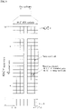
- a self-contained slot structure such as FIG. 5 may be taken into consideration.
- FIG. 5 is a diagram showing an example of a self-contained slot structure to which a method proposed in this disclosure may be applied.
- a deviant crease line area 510 indicates a downlink (DL) control region and a black portion 520 indicates an uplink (UL) control region.
- a portion 530 not having indication may be used for downlink data transmission or uplink data transmission.
- the characteristic of such a structure is that DL transmission and UL transmission are sequentially performed within one slot and DL data can be transmitted and UL Ack/Nack can also be transmitted and received within one slot.
- Such a slot may be defined as a "self-contained slot.”
- a base station can reduce the time taken to perform data retransmission to a UE when a data transmission error occurs and thus can minimize latency of the final data delivery.
- a base station and a UE require a time gap for a process of switching from a transmission mode to a reception mode or a process of switching from the reception mode to the transmission mode.
- some OFDM symbols when DL switches to UL are configured as a guard period (GP).
- a communication environment considered in embodiments of the present disclosure includes multi-carrier supporting environments. That is, a multi-carrier system or a carrier aggregation system used in the present disclosure means a system that aggregates and uses one or more component carriers (CCs) having a smaller bandwidth smaller than a target band at the time of configuring a target wideband in order to support a wideband.
- CCs component carriers
- a multi-carrier means an aggregation of carriers (alternatively carrier aggregation).
- the aggregation of carriers means both an aggregation between continuous carriers and an aggregation between non-contiguous carriers.
- the number of component carriers aggregated between downlink and uplink may be differently set.
- DL CC downlink component carriers
- UL CC uplink component carriers
- asymmetric aggregation a case where the number of downlink component carriers and the number of uplink component carriers are different is referred to as an "asymmetric aggregation.”
- the carrier aggregation may be used interchangeably with a term, such as a bandwidth aggregation or a spectrum aggregation.
- a carrier aggregation configured by combining two or more component carriers aims at supporting up to a bandwidth of 100 MHz in the LTE-A system.
- the bandwidth of the carriers to be combined may be limited to a bandwidth used in the existing system in order to maintain backward compatibility with the existing IMT system.
- the existing 3GPP LTE system supports bandwidths of 1.4, 3, 5, 10, 15, and 20 MHz and a 3GPP LTE-advanced system (that is, LTE-A) may be configured to support a bandwidth larger than 20 MHz by using on the bandwidth for compatibility with the existing system.
- the carrier aggregation system used in the preset invention may be configured to support the carrier aggregation by defining a new bandwidth regardless of the bandwidth used in the existing system.
- the LTE-A system uses a concept of the cell in order to manage a radio resource.
- the carrier aggregation environment may be called a multi-cell environment.
- the cell is defined as a combination of a pair of a downlink resource (DL CC) and an uplink resource (UL CC), but the uplink resource is not required. Therefore, the cell may be constituted by only the downlink resource or both the downlink resource and the uplink resource.
- the cell may have one DL CC and one UL CC, but when the specific terminal has two or more configured serving cells, the cell has DL CCs as many as the cells and the number of UL CCs may be equal to or smaller than the number of DL CCs.
- the DL CC and the UL CC may be configured. That is, when the specific terminal has multiple configured serving cells, a carrier aggregation environment having UL CCs more than DL CCs may also be supported. That is, the carrier aggregation may be appreciated as aggregation of two or more cells having different carrier frequencies (center frequencies).
- the described 'cell' needs to be distinguished from a cell as an area covered by the base station which is generally used.
- the cell used in the LTE-A system includes a primary cell (PCell) and a secondary cell (SCell.
- the P cell and the S cell may be used as the serving cell.
- a terminal which is in an RRC_CONNECTED state but does not have the configured carrier aggregation or does not support the carrier aggregation
- only one serving constituted by only the P cell is present.
- one or more serving cells may be present and the P cell and one or more S cells are included in all serving cells.
- the serving cell may be configured through an RRC parameter.
- PhysCellId as a physical layer identifier of the cell has integer values of 0 to 503.
- SCellIndex as a short identifier used to identify the S cell has integer values of 1 to 7.
- ServCellIndex as a short identifier used to identify the serving cell (P cell or S cell) has the integer values of 0 to 7. The value of 0 is applied to the P cell and SCellIndex is previously granted for application to the S cell. That is, a cell having a smallest cell ID (alternatively, cell index) in ServCellIndex becomes the P cell.
- the P cell means a cell that operates on a primary frequency (alternatively a primary CC).
- the terminal may be used to perform an initial connection establishment process or a connection re-establishment process and may be designated as a cell indicated during a handover process.
- the P cell means a cell which becomes the center of control associated communication among serving cells configured in the carrier aggregation environment. That is, the terminal may be allocated with and transmit the PUCCH only in the P cell thereof and use only the P cell to acquire the system information or change a monitoring procedure.
- An evolved universal terrestrial radio access may change only the P cell for the handover procedure to the terminal supporting the carrier aggregation environment by using an RRC connection reconfiguration message (RRCConnectionReconfigutaion) message of an upper layer including mobile control information (mobilityControlInfo).
- RRCConnectionReconfigutaion RRC connection reconfiguration message
- mobilityControlInfo mobile control information
- the S cell means a cell that operates on a secondary frequency (alternatively, secondary CC). Only one P cell may be allocated to a specific terminal and one or more S cells may be allocated to the specific terminal.
- the S cell may be configured after RRC connection establishment is achieved and used for providing an additional radio resource.
- the PUCCH is not present in residual cells other than the P cell, that is, the S cells among the serving cells configured in the carrier aggregation environment.
- the E-UTRAN may provide all system information associated with a related cell which is in an RRC_CONNECTED state through a dedicated signal at the time of adding the S cells to the terminal that supports the carrier aggregation environment.
- a change of the system information may be controlled by releasing and adding the related S cell and in this case, the RRC connection reconfiguration (RRCConnectionReconfigutaion) message of the upper layer may be used.
- the E-UTRAN may perform having different parameters for each terminal rather than broadcasting in the related S cell.
- the E-UTRAN adds the S cells to the P cell initially configured during the connection establishment process to configure a network including one or more S cells.
- the P cell and the S cell may operate as the respective component carriers.
- the primary component carrier (PCC) may be used as the same meaning as the P cell and the secondary component carrier (SCC) may be used as the same meaning as the S cell.
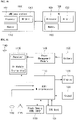
- FIG. 6 illustrates examples of a component carrier and carrier aggregation in the wireless communication system to which the present disclosure can be applied.
- FIG. 6(a) illustrates a single carrier structure used in an LTE system.
- the component carrier includes the DL CC and the UL CC.
- One component carrier may have a frequency range of 20 MHz.
- FIG. 6(b) illustrates a carrier aggregation structure used in the LTE system.
- a case is illustrated, in which three component carriers having a frequency magnitude of 20 MHz are combined.
- Each of three DL CCs and three UL CCs is provided, but the number of DL CCs and the number of UL CCs are not limited.
- the terminal may simultaneously monitor three CCs, and receive downlink signal/data and transmit uplink signal/data.
- the network may allocate M (M ⁇ N) DL CCs to the terminal.
- the terminal may monitor only M limited DL CCs and receive the DL signal.
- the network gives L (L ⁇ M ⁇ N) DL CCs to allocate a primary DL CC to the terminal and in this case, UE needs to particularly monitor L DL CCs.
- Such a scheme may be similarly applied even to uplink transmission.
- a linkage between a carrier frequency (alternatively, DL CC) of the downlink resource and a carrier frequency (alternatively, UL CC) of the uplink resource may be indicated by an upper-layer message such as the RRC message or the system information.
- a combination of the DL resource and the UL resource may be configured by a linkage defined by system information block type 2 (SIB2).
- the linkage may mean a mapping relationship between the DL CC in which the PDCCH transporting a UL grant and a UL CC using the UL grant and mean a mapping relationship between the DL CC (alternatively, UL CC) in which data for the HARQ is transmitted and the UL CC (alternatively, DL CC) in which the HARQ ACK/NACK signal is transmitted.
- a network may activate or deactivate the configured S cell(s).
- a P cell is always activated.
- the network activates or deactivates the S cell(s) by sending an activation/deactivation MAC control element.
- the activation/deactivation MAC control element has a fixed size and includes a single octet including seven C fields and one R field.
- the C field is configured for each S cell index "SCellIndex", and indicates the activation/deactivation state of the S cell. When the value of the C field is set to "1", it indicates that an S cell having a corresponding S cell index is activated. When the value of the C field is set to "0", it indicates that an S cell having a corresponding S cell index is deactivated.
- the UE maintains a timer "sCellDeactivationTimer" for each configured S cell and deactivates a related S cell when the timer expires.
- the same initial value of the timer is applied to each instance of the timer "sCellDeactivationTimer” and set by RRC signaling.
- initial S cell(s) are a deactivation state.
- the UE performs the following operation on each of the configured S cell(s) in each TTI.
- carrier aggregation deployment scenarios that may be taken into consideration in the 5G NR system may be the same as FIG. 7 .
- FIG. 7 illustrates examples of deployment scenarios into which carrier aggregations in an NR system are taken into consideration.
- F1 and F2 may mean a cell configured as a first frequency (or a first frequency band, a first carrier frequency or a first center frequency) and a cell configured as a second frequency (or a second frequency band, a second carrier frequency or a second center frequency).
- FIG. 7(a) illustrates a first CA deployment scenario.
- the F1 cell and the F2 cell may be co-located (or overlaid). In this case, both the two layers may provide sufficient coverage and mobility in the two layers may be supported.
- the first CA deployment scenario may include a case where the F1 cell and the F2 cell are present in the same band. In the first CA deployment scenario, it may be expected that an aggregation may be possible between the overlaid F1 cell and F2 cell.
- FIG. 7(b) illustrates a second CA deployment scenario.
- the F1 cell and the F2 cell may be co-located (or overlaid), but the F2 cell may support smaller coverage due to a greater path loss.
- the F1 cell provides sufficient coverage, and the F2 cell may be used to improve throughput.
- mobility may be performed based on the coverage of the F1 cell.
- the second CA deployment scenario may include a case where the F1 cell and the F2 cell are present in different bands (e.g., the F1 cell is present in ⁇ 800 MHz, 2 GHz ⁇ and the F2 cell is present in ⁇ 3.5 GHz ⁇ ).
- it may be expected that an aggregation may be possible between the overlaid F1 cell and F2 cell.
- FIG. 7(c) illustrates a third CA deployment scenario.
- the F1 cell and the F2 cell are co-located (or overlaid), but the antenna of the F2 cell may be connected to the boundary of the F2 cell in order to increase throughput at a cell edge.
- the F1 cell provides sufficient coverage, but the F2 cell may have a hole attributable to a potentially greater path loss.
- mobility may be performed based on the coverage of the F1 cell.
- the third CA deployment scenario may include a case where the F1 cell and the F2 cell are present in different bands (e.g., the F1 cell is present in ⁇ 800 MHz, 2 GHz ⁇ and the F2 cell is present in ⁇ 3.5 GHz ⁇ ).
- it may be expected that an aggregation may be possible in the area where coverage between the F1 cell and F2 cell of the same base station.
- FIG. 7(d) illustrates a fourth CA deployment scenario.
- the F1 cell provides macro coverage
- F2 remote radio heads (RRHs) may be used to improve throughput in a hot spot.
- mobility may be performed based on the coverage of the F1 cell.
- the fourth CA deployment scenario may include both a case where the F1 cell and the F2 cell correspond to a DL non-contiguous carrier in the same band (e.g., 1.7 GHz) and a case where the F1 cell and the F2 cell are present in different bands (e.g., the F1 cell is present in ⁇ 800 MHz, 2 GHz ⁇ and the F2 cell is present in ⁇ 3.5 GHz ⁇ ).
- FIG. 7(e) illustrates a fifth CA deployment scenario.
- the fifth CA deployment scenario is similar to the second CA deployment scenario, but frequency selective repeaters may be disposed so that coverage for one of carrier frequencies can be extended.
- it may be expected that an aggregation may be possible in the area where coverage is overlaid between the F1 cell and F2 cell of the same base station.
- a reception timing difference in the physical layer of UL grants and DL assignments for the same TTI may not affect a MAC operation.
- a UE may need to process a relative propagation delay difference up to 30 us from among CCs to be aggregated in both an intra-band discontiguous CA and an inter-band discontiguous CS. This may mean that the UE needs to process delay spread up to 30.26 us from among CCs monitored in a receiver because the time alignment of a base station is specified as a maximum of 0.26 us. Furthermore, this may mean that a UE must process a maximum uplink transmission timing difference between TAGs of 36.37 us with respect to an inter-band CA having multiple TAGs.
- frame timing and a system frame number (SFN) may be aligned over aggregated cells.
- the random access procedure is used for a UE to obtain uplink synchronization with an eNB or to have uplink radio resources allocated thereto.
- the UE When the UE is powered on, the UE obtains downlink synchronization with an initial cell and receives system information.
- the UE obtains information about a set of available random access preambles and radio resources used to send a random access preamble from the system information.
- the radio resources used to send the random access preamble may be specified as a combination of at least one subframe index and an index in a frequency domain.
- the UE sends a random access preamble randomly selected from the set of random access preambles.
- An eNB that has received the random access preamble sends a timing alignment (TA) value for uplink synchronization to the UE through a random access response. Accordingly, the UE obtains uplink synchronization.
- TA timing alignment
- the random access procedure is common to frequency division duplex (FDD) and time division duplex (TDD).
- FDD frequency division duplex
- TDD time division duplex
- the random access procedure is not related to a cell size and is also not related to the number of serving cells if a component aggregation (CA) has been configured.
- CA component aggregation
- the UE may perform the random access procedure as in the following cases.
- a method for applying a timing advance (TA) value applicable to one specific cell (e.g., a P cell) to a plurality of cells in common in a radio access system supporting a component aggregation has been taken into consideration.
- a UE may aggregate a plurality of cells belonging to different frequency bands (i.e., greatly spaced apart on the frequency) or a plurality of cells having different propagation properties.
- a eNB i.e., a macro eNB
- a secondary eNB i.e., repeater
- RRH remote radio header
- a small cell such as a femto cell or a pico cell, or the SeNB has been disposed within the cell
- a plurality of cells may have different delay properties.
- a plurality of TAs may be used in a CA situation in which a plurality of cells has been aggregated.
- the independent allocation of the TAs may be taken into consideration for each specific cell group. This is called a TA group (TAG).
- the TAG may include one or more cells.
- the same TA may be applied to one or more cells included in a TAG in common.
- an MAC TA command control element includes a TAG identity (ID) of 2 bits and a TA command field of 6 bits.
- a UE in which a CA has been configured performs a random access procedure if it performs the random access procedure in relation to a P cell.
- a TAG to which the P cell belongs i.e., a primary TAG (pTAG)
- pTAG primary TAG
- TA determined based on the P cell or coordinated through a random access procedure involved in the P cell may be applied to all of cell(s) within the pTAG.
- a TAG including only an S cell i.e., a secondary TAG (sTAG)
- sTAG secondary TAG
- TA determined based on a specific S cell within the sTAG may be applied to all of cell(s) within the corresponding sTAG.
- the TA may be obtained by a random access procedure initiated by an eNB.
- the S cell is configured as a random access channel (RACH) resource within the sTAG.
- RACH random access channel
- the eNB requests RACH access in the S cell. That is, the eNB initiates RACH transmission on S cells in response to a PDCCH order transmitted in the P cell.
- a response message for an S cell preamble is transmitted through a P cell using an RA-RNTI.
- the UE may apply TA, determined based on an S cell to which random access has been successfully completed, to all of cell(s) within a corresponding sTAG.
- the random access procedure may be performed even in an S cell in order to obtain the TA of an sTAG to which the S cell belongs even in the corresponding S cell.
- An LTE/LTE-A system provides a contention-based random access procedure for randomly selecting, by a UE, one preamble within a specific set and using the selected preamble and a non-contention-based random access procedure for using a random access preamble allocated to only a specific UE by an eNB in a process of selecting a random access preamble (RACH preamble).
- the non-contention-based random access procedure may be used for only UE positioning and/or timing advance alignment for an sTAG if it is requested in the handover process or in response to a command from the eNB. After the random access procedure is completed, common uplink/downlink transmission is performed.
- a relay node also supports both the contention-based random access procedure and the non-contention-based random access procedure.
- a relay node performs the random access procedure, it suspends an RN subframe configuration at that point of time. That is, this means that it temporarily discards an RN subframe. Thereafter, an RN subframe configuration is restarted at a point of time at which a random access procedure is successfully completed.
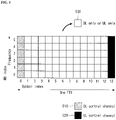
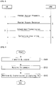
- FIG. 8 is a diagram for illustrating a contention-based random access procedure in a wireless communication system to which an embodiment of the present disclosure may be applied.
- a UE randomly selects one random access preamble (RACH preamble) from a set of random access preambles indicated by system information or a handover command, selects a physical RACH (PRACH) resource capable of sending the random access preamble, and sends the selected physical RACH (PRACH).
- RACH preamble random access preamble
- PRACH physical RACH
- the random access preamble is transmitted through 6 bits in an RACH transport channel.
- the 6 bits include a random identity of 5 bits for identifying the UE that has performed RACH transmission and 1 bit (e.g., indicate the size of a third message Msg3) for indicating additional information.
- An eNB that has received the random access preamble from the UE decodes the random access preamble and obtains an RA-RNTI.
- the RA-RNTI related to the PRACH in which the random access preamble has been transmitted is determined by the time-frequency resource of the random access preamble transmitted by the corresponding UE.
- the eNB sends a random access response, addressed by the RA-RNTI obtained through the preamble on the first message, to the UE.
- the random access response may include a random access (RA) preamble index/identifier, uplink (UL) assignment providing notification of uplink radio resources, a temporary C-RNTI, and a time alignment command (TAC).
- the TAC is information indicative of a time alignment command that is transmitted from the eNB to the UE in order to maintain uplink time alignment.
- the UE updates uplink transmission timing using the TAC. When the UE updates time synchronization, it initiates or restarts a time alignment timer.
- An UL grant includes uplink resource allocation used for the transmission of a scheduling message (third message) to be described later and a transmit power command (TPC).
- TPC transmit power command
- the UE After the UE sends the random access preamble, it attempts to receive its own random access response within a random access response window indicated by the eNB through system information or a handover command, detects a PDCCH masked with an RA-RNTI corresponding to the PRACH, and receives a PDSCH indicated by the detected PDCCH.
- Information about the random access response may be transmitted in the form of a MAC packet data unit (PDU).
- the MAC PDU may be transferred through the PDSCH.
- the PDCCH may include information about the UE that needs to receive the PDSCH, information about the frequency and time of the radio resources of the PDSCH, and the transmission format of the PDSCH. As described above, once the UE successfully detects the PDCCH transmitted thereto, it may properly receive the random access response transmitted through the PDSCH based on the pieces of information of the PDCCH.
- the random access response window means a maximum time interval during which the UE that has sent the preamble waits to receive the random access response message.
- the random access response window has a length of "ra-ResponseWindowSize" that starts from a subframe subsequent to three subframes from the last subframe in which the preamble is transmitted. That is, the UE waits to receive the random access response during a random access window secured after three subframes from a subframe in which the preamble has been transmitted.
- the UE may obtain the parameter value of a random access window size "ra-ResponseWindowsize" through the system information.
- the random access window size may be determined to be a value between 2 and 10.
- the UE When the UE successfully receives the random access response having the same random access preamble index/identifier as the random access preamble transmitted to the eNB, it suspends the monitoring of the random access response. In contrast, if the UE has not received a random access response message until the random access response window is terminated or the UE does not receive a valid random access response having the same random access preamble index as the random access preamble transmitted to the eNB, the UE considers the reception of a random access response to be a failure and then may perform preamble retransmission.
- the reason why the random access preamble index is necessary for the random access response is to provide notification that an UL grant, a TC-RNTI and a TAC are valid for which UE because random access response information for one or more UEs may be included in one random access response.
- the UE When the UE receives a valid random access response, it processes each of pieces of information included in the random access response. That is, the UE applies a TAC to each of the pieces of information and stores a TC-RNTI. Furthermore, the UE sends data, stored in the buffer of the UE, or newly generated data to the eNB using an UL grant. If the UE performs first connection, an RRC connection request generated in the RRC layer and transferred through a CCCH may be included in the third message and transmitted. In the case of an RRC connection re-establishment procedure, an RRC connection re-establishment request generated in the RRC layer and transferred through a CCCH may be included in the third message and transmitted. Furthermore, the third message may include an NAS access request message.
- the third message may include the identity of the UE.
- the eNB In the contention-based random access procedure, the eNB is unable to determine which UE can perform the random access procedure. The reason for this is that the UE has to be identified in order to perform a collision resolution.
- a method for including the identity of UE includes two methods.
- the first method if UE has already had a valid cell identity(C-RNTI) allocated in a corresponding cell prior to a random access procedure, the UE sends its own cell identity through an uplink transmission signal corresponding to an UL grant.
- the UE if a valid cell identity has not been allocated to the UE prior to a random access procedure, the UE includes its own unique identity (e.g., an S-TMSI or a random number) in an uplink transmission signal and sends the uplink transmission signal.
- the unique identity is longer than a C-RNTI.
- UE-specific scrambling is used.
- the scrambling may not be based on the C-RNTI, and instead a TC-RNTI received in a random access response is used. If the UE has sent data corresponding to the UL grant, it initiates a timer for a collision resolution (i.e., a contention resolution timer).
- a collision resolution i.e., a contention resolution timer
- the eNB When the C-RNTI of the UE is received through the third message from the UE, the eNB sends a fourth message to the UE using the received C-RNTI.
- the eNB receives a unique identity (i.e., an S-TMSI or a random number) through the third message from the UE, it sends the fourth message to the UE using a TC-RNTI allocated to the corresponding UE in a random access response.
- the fourth message may correspond to an RRC connection setup message including a C-RNTI.
- the UE After the UE sends data including its own identity through the UL grant included in the random access response, it waits for an instruction from the eNB for a collision resolution. That is, the UE attempts to receive a PDCCH in order to receive a specific message.
- a method for receiving the PDCCH includes two methods. As described above, if the third message transmitted in response to the UL grant includes a C-RNTI as its own identity, the UE attempts the reception of a PDCCH using its own C-RNTI. If the identity is a unique identity (i.e., an S-TMSI or a random number), the UE attempts the reception of a PDCCH using a TC-RNTI included in the random access response.
- the UE determines that the random access procedure has been normally performed and terminates the random access procedure.
- the UE checks data in which a PDSCH indicated by the PDCCH is transferred. If, as a result of the check, it is found that the unique identity of the UE has been included in the contents of the data, the UE determines that the random access procedure has been normally performed and terminates the random access procedure. The UE obtains the C-RNTI through the fourth message. Thereafter, the UE and a network send or receive a UE-dedicated message using the C-RNTI.
- the reason why a collision occurs in performing random access is that the number of random access preambles is basically limited. That is, a UE randomly selects one of common random access preambles and sends the selected random access preamble because an eNB cannot assign a random access preamble unique to a UE to all of UEs. Accordingly, two or more UEs may select the same random access preamble and send it through the same radio resources (PRACH resource), but the eNB determines the received random access preambles to be one random access preamble transmitted by one UE. For this reason, the eNB sends a random access response to the UE, and expects that the random access response will be received by one UE.
- PRACH resource radio resources
- the eNB performs an operation according to the reception of each random access response for each UE. That is, there is a problem in that the two or more UEs send different data through the same radio resources using one UL grant included in the random access response. Accordingly, the transmission of the data may all fail, and the eNB may receive only the data of a specific UE depending on the location or transmission power of the UEs. In the latter case, all of the two or more UEs assume that the transmission of their data was successful, and thus the eNB has to notify UEs that have failed in the contention of information about the failure. That is, providing notification of information about the failure or success of the contention is called a collision resolution.
- a collision resolution method includes two methods. One method is a method using a collision resolution timer, and the other method is a method of sending the identity of a UE that was successful in a contention to other UEs.
- the former method is used when a UE already has a unique C-RNTI prior to a random access process. That is, the UE that has already had the C-RNTI sends data, including its own C-RNTI, to an eNB in response to a random access response, and drives a collision resolution timer. Furthermore, when PDCCH information indicated by its own C-RNTI is received before the collision resolution timer expires, the UE determines that it was successful in the contention and normally terminates the random access.
- the UE determines that it failed in the contention and may perform a random access process again or may notify a higher layer of the failure of the contention.
- the method of sending the identity of a successful UE is used if a UE does not have a unique cell identity prior to a random access process. That is, if the UE does not have its own cell identity, the UE includes an identity (or an S-TMSI or a random number) higher than the cell identity in data based on UL grant information included in a random access response, sends the data, and drives a collision resolution timer.
- the UE determines that the random access process was successful. In contrast, if data including its own higher identity is not received through a DL-SCH before the collision resolution timer expires, the UE determines that the random access process has failed.
- the operation in the non-contention-based random access procedure is terminated by only the transmission of the first message and the second message.
- the eNB allocates the random access preamble to the UE, and the UE sends the allocated random access preamble to the eNB as the first message and receives a random access response from the eNB. Accordingly, the random connection procedure is terminated.
- the numerology may mean subcarrier spacing and a cyclic prefix (CP).
- this disclosure proposes a method of supporting timing adjustment, that is, transmission/reception timing adjustment, in the carrier aggregation (CA) situation of an NR system in which numerology may be different for each CC and/or between CCs.
- CA carrier aggregation
- Timing advance (TA) described in this disclosure may mean a timing offset applied in a UE for synchronization between an uplink (UL) subframe and a downlink (DL) subframe in order for a base station to perform orthogonal DL/UL transmission and reception.
- TA Timing advance
- the NR system can support multiple timing advance groups (TAGs), that is, multiple TAGs, by taking into consideration the aforementioned CA deployment scenarios (e.g., the fourth CA deployment scenario (HetNet)).
- TAGs timing advance groups
- HetNet fourth CA deployment scenario
- a TAG that belongs to TAGs and that includes a PCell may be denoted as a pTAG
- a TAG that belongs to TAGs and that includes only an SCell may be denoted as an sTAG.
- initial timing information about an initial pTAG may be obtained through a random access procedure (RA procedure). Thereafter, timing information about an sTAG may be obtained through a contention-free RA procedure (or non-contention RA procedure) based on a PDCCH (or NPDCCH) order by taking into consideration the state in which a UE has set up an RRC connection (i.e., RRC_CONNECTED state).
- RA procedure random access procedure
- PDCCH or NPDCCH
- a method of obtaining pTAG timing information a method of obtaining sTAG timing information, a method of configuring a TA command, a method of configuring activation/re-activation timing of an SCell, and a method of determining a timing difference requirement are described in detail by taking into consideration a carrier aggregation (CA) operation in the aforementioned NR system.
- CA carrier aggregation
- a random access procedure (hereinafter referred to as an "RA procedure") may be used as the method of obtaining pTAG timing information by taking into consideration a CA operation in the NR system.
- RA preamble a random access preamble
- a contention-based RA procedure or a contention-free RA procedure may be used as an RA procedure for obtaining TA information about a pTAG.
- numerology of each component carrier may be selected from among various values (e.g., subcarrier spacings 15 kHz, 30 kHz, 60 kHz, and 120 kHz)
- a difference between the various values may need to be taken into consideration.
- the length of a symbol, a slot and/or a subframe may be differently set based on a difference between subcarrier spacings.
- a difference, such as differently set transmission timing or counter size in each step may need to be taken into consideration.
- Method 1 a procedure of obtaining pTAG timing information
- Method 1-2 a method 1-2 using a contention-free RA procedure
- Method 1) and method 2) have been divided for convenience of description only, and they may be applied by combining them or substituting some elements.
- a base station e.g., gNB
- a preamble i.e., the aforementioned Msg 1
- it may transmit an RAR message (i.e., a message in a second step, that is, the aforementioned Msg 2) to the UE within a random access response (RAR) window that starts after a specific time from the transmission start point (e.g., n-th subframe) of a preamble.
- RAR random access response
- the start point and end point of the RAR window may be configured in a subframe and/or slot unit.
- the RAR window may be configured to start in an (n+k0)-th subframe.
- n may be the transmission start subframe of a preamble or may correspond to the last subframe.
- an absolute time corresponding to k0 may be scaled (i.e., expanded or reduced based on a specific condition/value) based on numerology of a CC. Accordingly, a preparation time for RAR transmission in a base station is insufficient or a disadvantage may occur in the latency or power aspect because the preparation time is excessively increased.
- a k0 value may be configured as an absolute time or RAR window timing may be configured in a symbol, slot and/or subframe unit configured in association with numerology or independently.
- the set value may be applied to all of numerologies in common or may be differently applied for each numerology.
- the aforementioned method of configuring RAR window timing in association with numerology may be a method of interpreting an RAR window start point as a k0 ⁇ M subframe by taking into consideration that the length of a subframe is reduced to 1/M when subcarrier spacing is increased M times.
- a configuration may be performed so that an RAR message (i.e., Msg 2) transmitted from a base station to a UE is transmitted in an (n+k1)-th subframe within an RAR window.
- n may be the transmission start subframe of a preamble or may correspond to the last subframe.
- a k1 value may be configured as an absolute time or RAR window timing may be configured in a symbol, a slot and/or a subframe unit configured in association with numerology or independently.
- the set value may be applied to all of numerologies in common or may be differently applied for each numerology.
- the aforementioned method of configuring RAR transmission timing in association with numerology may be a method of interpreting an RAR transmission start point as a k1 ⁇ M subframe by taking into consideration that the length of the subframe is reduced to 1/M when subcarrier spacing is increased M times.
- a UE may transmit the message (i.e., the aforementioned Msg 3) of a third step after a specific time from an RAR reception subframe (i.e., a subframe in which an RAR has been received). For example, assuming that the RAR reception subframe is an n-th subframe, the UE may be configured to transmit the message of the third step in an (n+k2)-th subframe.
- a k2 value may be configured as an absolute time or window timing for the message of the third step may be configured in a symbol, a slot and/or a subframe unit configured in association with numerology or independently.
- the set value may be applied to all of numerologies in common or may be differently applied for each numerology.
- the aforementioned method of configuring transmission timing for Msg 3 in association with numerology may be a method of interpreting a transmission start point for Msg 3 as a k2 ⁇ M subframe by taking into consideration that the length of the subframe is reduced to 1/M when subcarrier spacing is increased M times.
- a method of obtaining pTAG timing information using a contention-free RA procedure is described below.
- a UE When a UE receives information about a PDCCH order (PDCCH order) from a base station (e.g., gNB), the UE may transmit the message (i.e., Msg 1) of a first step through a PDCCH resource generated (or assigned) after a specific time from a subframe (e.g., an n-th subframe) to which a PDCCH order belongs.
- a minimum value of transmission timing of the message i.e., transmission timing of Msg 1 of the first step may be configured in a subframe unit.
- the UE may be configured to transmit a preamble through a PRACH resource at the earliest point of time that starts from an (n+k0)-th subframe or thereafter. Since a subframe length is differently set based on numerology of a CC, an absolute time corresponding to k0 is scaled (i.e., expanded or reduced based on a specific condition/value). Accordingly, a preparation time for the transmission of a preamble in the UE is insufficient or a disadvantage may occur in the latency or power aspect because the preparation time is excessively increased.
- a k0 value is configured (or set) as an absolute time or may be configured in a symbol, a slot and/or a subframe unit configured in association with numerology or independently.
- the configured value may be applied to all of numerologies in common or may be differently applied for each numerology.
- the aforementioned method of configuring a k0 value in association with numerology may be a method of interpreting the start point of message (i.e., Msg 1) transmission of a first step as a k0 ⁇ M subframe by taking into consideration that when subcarrier spacing is increased M times, the length of the subframe is reduced to 1/M.
- an RAR window configuration and RAR transmission timing may be configured as an absolute time or may be configured in a symbol, a slot and/or a subframe unit configured in association with numerology or independently.
- the configured value may be applied to all of numerologies in common or may be differently applied for each numerology.
- transmission timing of the message of a third step may be configured as an absolute time or may be configured in a symbol, a slot and/or a subframe unit configured in association with numerology or independently. Even in this case, the configured value may be applied to all of numerologies in common or may be differently applied for each numerology.
- a method of obtaining sTAG timing information by taking into consideration a CA operation in the NR system is described.
- an RA procedure may be used as the method of obtaining sTAG timing information by taking into consideration a CA operation in the NR system.
- a UE may enter an RRC connection setup state (RRC_CONNECTED state).
- RRC_CONNECTED state RRC connection setup state
- an SCell may be activated through an SCell addition procedure for a configured SCell.
- a base station e.g., gNB
- gNB may signal the UE as to which the SCell belongs to the pTAG or an sTAG.
- the SCell may share the same TA command with the PCell. If not, that is, the SCell belongs to an sTAG, the UE may perform an RA procedure for the activated SCell in order to obtain timing information about the sTAG.
- the RA procedure performed by the UE may be initiated when the base station transmits a PDCCH order because the corresponding UE is already in the RRC connection setup state.
- the PDCCH order may be for an SCell that wants to obtain timing information or another activated SCell (i.e., scheduled SCell) that belongs to the same sTAG as the corresponding SCell.
- a case where a UE receives a PDCCH order from an SCell that transmits a preamble may be assumed by taking into consideration the PDCCH order according to self-carrier scheduling.
- the UE when the UE receives the PDCCH order from a base station, the UE may transmit the message (i.e., Msg 1) of a first step through a PDCCH resource generated (or assigned) after a specific time from a subframe (e.g., n-th subframe) to which the PDCCH order belongs.
- a minimum value of transmission timing of the message i.e., transmission timing for Msg 1 of the first step may be configured in a subframe unit.
- a UE may be configured to transmit a preamble through a PRACH resource at the earliest point of time that starts from an (n+k0)-th subframe or thereafter.
- a k0 value may be configured as an absolute time or may be configured in a symbol, a slot and/or a subframe unit configured in association with numerology or independently.
- the set value may be applied to all of numerologies in common or may be differently applied for each numerology.
- the aforementioned method of setting a k0 value in association with numerology may be a method of interpreting the start point of message (i.e., Msg 1) transmission of the first step as a k0 ⁇ M subframe by taking into consideration th at the length of a subframe is reduced to 1/M when subcarrier spacing is increased M times.
- an RAR window configuration and RAR transmission timing may be configured as an absolute time or may be configured in a symbol, a slot and/or a subframe unit configured in association with numerology or independently.
- the set value may be applied to all of numerologies in common or may be differently applied for each numerology.
- transmission timing of the message (i.e., Msg 3) of the third step may be configured as an absolute time or may be configured in a symbol, a slot and/or a subframe unit configured in association with numerology or independently.
- the set value may be applied to all of numerologies in common or may be differently applied for each numerology.
- a UE may determine the timings (e.g., Msg 1 transmission timing, RAR window timing, RAR transmission timing and Msg 3 transmission timing) of the steps through an RA procedure for a PCell before it performs an RA procedure on an SCell. Accordingly, in this case, timing in each step of an RA procedure for a pTAG may be identically applied to the RA procedure for the SCell. Alternatively, the UE may configure and use timing in each step separately from the PCell according to the aforementioned method. Alternatively, timing in each step of the RA procedure for the pTAG may be applied identically conditionally if the numerologies of an SCell and a PCell that want to obtain TA information are the same or correspond to a specific combination.
- the timings e.g., Msg 1 transmission timing, RAR window timing, RAR transmission timing and Msg 3 transmission timing
- an initial timing adjustment procedure in the NR system may be performed as follows.
- a base station estimates initial TA from a preamble (i.e., RA preamble) transmitted by a UE and may then transmit a TA command to the UE in a next step (i.e., RAR transmission step). Thereafter, the UE may transmit a message (i.e., Msg 3) by adjusting the message (i.e., Msg 3) transmission timing of a third step to the initial TA received through the TA command, and may enter (or reach) an RRC connection setup state through the remaining RA procedure.
- a message i.e., Msg 3
- TA tracking may be performed through a specific uplink signal (e.g., a PUSCH, a PUCCH or an SRS).
- a specific uplink signal e.g., a PUSCH, a PUCCH or an SRS.
- the TA tracking may mean an operation of determining whether TA needs to be modified or updated based on the uplink signal transmitted by the UE.
- the base station may instruct the UE to perform TA modification (or correction or update) by transmitting a TA command medium access control-control element (MAC-CE) to the UE.
- MAC-CE medium access control-control element
- the TA command MAC-CE may mean a message configured to transmit the TA command in the MAC layer.
- the time (i.e., offset) from timing when the UE has received the TA command to timing when the UE first corrects the TA in an uplink subframe (or slot) using a received TA value may be configured in a subframe unit (or slot unit).
- the UE may be configured to perform uplink transmission by incorporating a TA command received in an (n+k)-th subframe.
- the subframe unit can be scaled (i.e., expanded or reduced) according to subcarrier spacing.
- timing into which the TA command is incorporated may be configured as an absolute time or may be configured in a symbol, a slot and/or a subframe unit configured in association with numerology or independently.
- the TA command may be configured taking into consideration a maximum supportable radius of a cell and control (e.g., control resolution) within a cyclic prefix (CP).
- CP cyclic prefix
- the TA command in the NR system may be configured using at least one of the following method 3-1) to method 3-3).
- the method 3-1) to method 3-3) have been classified for convenience of description and may be applied by combining them or substituting some elements.
- a frequency resource region described in the present embodiment may be interpreted as a concept corresponding to a cell.
- numerology of a specific cell may be the same as numerology configured in a specific frequency resource region.
- the unit of a TA command may mean a TA value indicated by a TA command or the unit of a corresponding value, and may mean a unit in which a TA command is instructed or interpreted for a UE.
- the unit of a TA command may be configured as an absolute time (e.g., microseconds (us), etc.). That is, a TA value or the unit of a TA value indicated by a TA command may be represented as an absolute time.
- a maximum TA value (this may have a correlation with the size of TA) may be set as a fixed value. Furthermore, a corresponding method may be identically applied to all of numerologies.
- the unit of a TA command may be interpreted in association with numerology of a frequency resource region (e.g., cell, Component Carrer (CC), etc.) to which TA will be applied. That is, the TA command may be (scaled and) interpreted based on numerology of a frequency resource region to which the corresponding TA will be applied.
- a frequency resource region e.g., cell, Component Carrer (CC), etc.
- a maximum TA value (this may be related to the size of the TA) may be set as a fixed value or may be set by a base station.
- the maximum TA value may be delivered as system information (SI) through broadcast information (e.g., system information block (SIB)).
- SI system information
- SIB system information block
- the corresponding method may mean a method of interpreting the value of TA indicated by a TA command by scaling (i.e., expanding or reducing) the value based on subcarrier spacing.
- the unit of a TA command is determined by a base station, and information about a TA command is broadcasted through system information (e.g., system information block). That is, the unit of a TA command is configured by a base station, and information about the unit of a TA command is delivered through a system information block.
- system information e.g., system information block
- a maximum TA value (this may have a correlation with the size of TA) may also be set by a base station or may be set as a fixed value.
- the system information block may be implicitly indicated through a PRACH format configuration.
- Method 3-1) the selection or application of Method 3-3) may be differently taken into consideration.
- Method 3-1) may be applied because a base station cannot assume that a UE is now in which state (e.g., RRC setup connection state).
- Method 3-2) that is operating or based on a specific numerology (e.g., reference numerology) may be applied.
- a method of configuring an absolute time and/or a method of configuring a TA command based on numerology in particular, numerology of a frequency resource region (e.g., a frequency domain corresponding to a specific cell) to which corresponding TA will be applied with respect to a TA command may be applied.
- numerology e.g., a frequency domain corresponding to a specific cell
- Method 3-2 into which numerology is incorporated is applied because a base station can be aware that the state of the UE is in the RRC connection setup state.
- Method 3-3) may be applied for the flexibility of a TA command configuration.
- a TA command transmitted by the base station is interpreted based on numerology of a frequency resource region to which the corresponding TA will be applied.
- a TA command indicated by the corresponding TA is delivered to the UE through a MAC-CE.
- Method 3-1) may be applied because a base station cannot assume that the UE is now in which state (e.g., RRC setup connection state).
- Method 3-2) is applied based on an operating or specific numerology (e.g., reference numerology).
- Method 3-2 in which numerology is taken into consideration may be applied because a base station can be aware that the state of a UE is in an RRC connection setup state.
- Method 3-3) may be applied for the flexibility of a TA command configuration.
- a method of configuring a TA command i.e., the unit of a TA command
- a maximum TA value this may have a correlation with the size of TA
- a base station is aware of numerology of a UE (i.e., numerology applied for the UE to perform uplink transmission) (e.g., in the case of the first example and/or the second example) is described in detail.
- a TA command and/or a maximum TA value may be configured based on a specific numerology (e.g., the largest subcarrier spacing) belonging to the TAG. That is, if the TAG consists of multiple numerologies, the TA command and/or maximum TA value for the corresponding TAG may be configured or interpreted based on a specific numerology configuring the corresponding TAG. Such a method may be performed as in a next example.
- Method 3-2 if Method 3-2) or Method 3-3) is selected and applied, a method of configuring a TA command and/or maximum TA value based on a specific subcarrier spacing belonging to a TAG may be taken into consideration. That is, a reference for configuring or interpreting the range of a TA command may be configured as a specific one of multiple subcarrier spacings belonging to a corresponding TAG.
- the unit of a TA command may be configured as the largest subcarrier spacing unit and/or a maximum TA value may be configured as a minimum subcarrier spacing unit.
- the largest subcarrier spacing and the minimum subcarrier spacing may mean a maximum value and minimum value of subcarrier spacings of multiple resource regions respectively configuring corresponding TAGs.
- the TA command unit 16Ts of the LTE system is applied to a case where the subcarrier spacings of frequency resource regions (e.g., cells) configuring a TAG in the NR system are 15 kHz and 60 kHz, respectively, without any change, the CP length of a TA command is reduced to 1/4 in the 16Ts state in a frequency resource region using the 60 kHz subcarrier spacing.
- frequency resource regions e.g., cells
- subcarrier spacings 15 kHz and 120 kHz
- TA adjustment itself is practically impossible because 1 TA adjustment unit is present within a CP.
- TA fine adjustment of at least LTE system level can be supported with respect to all of frequency resource regions (e.g., cells) configuring a TAG regardless of numerology by configuring the aforementioned TA command (i.e., TA command unit) as the largest subcarrier spacing unit. For example, about 9 TA command units may be configured to be present within a CP length through such a method.
- CP length is in reverse proportion to a subcarrier spacing if CP overhead is the same.
- CP overhead i.e., a ratio of a CP length and an OFDM symbol valid period
- a maximum TA value may be set based on a minimum subcarrier spacing of a frequency resource region (e.g., cell) configuring a TAG. For example, if different cell ranges are supported through different subcarrier spacings in the same site (e.g., if a minimum subcarrier spacing is used for services supporting a maximum cell range or if the largest subcarrier spacing is used for services supporting a minimum cell range), the same TAG may be configured due to the same site. In this case, in order to support up to service supporting maximum cell range using the same TA command, a maximum TA value may be configured based on the minimum subcarrier spacing.
- a TA command i.e., TA command unit
- a maximum TA value may be determined based on the subcarrier spacing of a component carrier (CC) that has transmitted the corresponding signal.
- a transmitted uplink signal may be previously configured or defined.
- a TA command i.e., TA command unit
- a maximum TA value may be configured to be determined based on the subcarrier spacing of a configured uplink signal or an actually transmitted uplink signal of configured uplink signals.
- Such a method has an advantage in that the size of a TA command field can be optimized compared to a method of configuring a TA command unit based on the largest subcarrier spacing of multiple subcarrier spacings configuring a corresponding TAG and determining a maximum TA value based on a minimum subcarrier spacing. That is, this method has an advantage in the overhead reduction aspect of a TA command field.
- a TA command i.e., TA command unit
- a maximum TA value may be determined based on the subcarrier spacing of a component carrier (CC) used by a base station when it transmits an (N)PDCCH order.
- CC component carrier
- An RA procedure based on an (N)PDCCH order is an operation in the RRC connection setup state and is a method for a base station to instruct a specific UE to perform an RA procedure on a specific frequency resource region (e.g., cell). Accordingly, there is an advantage in that the size of a TA command field can be optimized because a TA command unit and a maximum TA value are configured based on the subcarrier spacing of a corresponding frequency resource region (e.g., cell), compared to a method of configuring a TA command unit based on the largest subcarrier spacing and determining a maximum TA value based on a minimum subcarrier spacing. That is, there is an advantage in the overhead reduction aspect of a TA command field.
- the bit field sizes of the initial TA command and the tracking TA command is differently set or a minimum adjustment unit is differently configured.
- a maximum adjustment range may be configured smaller than the case of an initial TA command and a minimum adjustment unit may be configured smaller than the case of an initial TA command.
- bit fields of the same size or different sizes may be configured to be differently interpreted depending on an initial TA command or a tracking TA command.
- information configured by a base station may be broadcasted as system information or may be implicitly delivered through a PRACH format configuration.
- a TA adjustment unit (e.g., Ts" or Tc") practically applied by a UE may be determined according to the following methods.
- Ts may be determined based on a maximum bandwidth that may be configured in a corresponding frequency band.
- a TA reference adjustment unit Ts' (or Tc') may be determined based on the determined Ts (or Tc).
- Ts' may be expressed as k ⁇ Ts.
- k may be determined based on an operating or specific (reference) numerology (e.g., a specific subcarrier spacing or a specific CP).
- an actual TA adjustment unit of a UE may be determined based on a relation with the operating or specific (reference) numerology.
- the TA adjustment unit Ts" of the UE may be expressed as m ⁇ Ts' (i.e., m ⁇ k ⁇ Ts).
- m may mean a reference subcarrier spacing/UE subcarrier spacing if only a subcarrier spacing is taken into consideration. For example, if the reference subcarrier spacing is 15 kHz and the UE subcarrier spacing is 60 kHz, m may be 1/4.
- a TA command may be configured as a combination of numerologies belonging to the TAG. For example, if a TA adjustment unit of a E having a first subcarrier spacing is Ts_1 and a TA adjustment unit of a UE having a second subcarrier spacing is Ts_2, a TA command may be configured in the form of a ⁇ Ts_1 + b ⁇ Ts_2.
- one SCell or some or all of multiple-configured SCells not used by a UE may be deactivated in order to reduce power.
- a method of activating the one SCell or some or all of the multiple-configured SCells again if the corresponding UE requires the one SCell or some or all of the multiple-configured SCells may be taken into consideration.
- the UE may be configured to start the deactivation timer (i.e., SCellDeactivationTimer) of the SCell after a specific time from the reception of the activation or deactivation indication or to restart the deactivation timer in the case of reactivation.
- the start point of the corresponding timer may be configured in a subframe or slot unit.
- the corresponding timer may be configured to start or restart in an (n+k3)-th subframe.
- the following methods 4-1) to 4-3) may be taken into consideration when the start or restart timing of the deactivation timer of an SCell is configured.
- the start or restart timing of the deactivation timer of an SCell may include SRS transmission timing, CSI reporting timing, PDCCH monitoring timing and/or power headroom report (PHR) triggering timing after SCell (re)activation.
- SRS transmission timing CSI reporting timing
- PDCCH monitoring timing PDCCH monitoring timing
- PHR power headroom report
- timing related to the activation or reactivation of an SCell may be configured as an absolute time (e.g., microseconds (us), etc.).
- Method 4-1 may be identically applied to all of numerologies.
- timing related to the activation or reactivation of an SCell may be interpreted in association with the numerology of a corresponding cell (i.e., the frequency resource region of a corresponding cell).
- the value of the corresponding timing may be scaled based on subcarrier spacing and interpreted.
- timing related to the activation or reactivation of an SCell may be determined by a base station, and corresponding information may be broadcasted through system information (e.g., system information block). That is, a base station may configure timing related to the activation or reactivation of an SCell and broadcast the timing through a system information block.
- system information e.g., system information block
- the cell radius and the number of TAGs may be configured to be limited by taking into consideration the buffer size of a receiver. To this end, a requirement for a timing difference that may be tolerated by a UE needs to be configured. When a cell radius and/or the number of TAGs are determined, such a requirement may be taken into consideration.
- a maximum receiver bandwidth and a cyclic prefix (CP) that may be configured in a corresponding frequency band may need to be taken into consideration.
- the reason for this is that if the same UE buffer size is assumed, delay that may be tolerated when control information is more delayed than data in the downlink and reaches a UE may be reduced because data throughput increases as a receiver bandwidth becomes greater and a CP becomes smaller.
- a UE buffer size is related to UE capability, the number of TAGs supportable by a corresponding UE may be limited depending on the UE buffer size or UE capability.
- a method of restricting cross-carrier scheduling by taking into consideration a burden of a receiver buffer size for a scheduled cell and/or HARQ latency for a scheduled cell may also be taken into consideration.
- cross-CC scheduling between two component carriers (CCs) in which a TA difference exceeds "X us” and/or a difference between subcarrier spacings exceeds "Y times” may not be permitted.
- cross-CC scheduling between two CCs in which a difference between the TA of a scheduling cell and the TA of a scheduled cell exceeds "X us” and/or the subcarrier spacing of a scheduling cell is "Y times" than the subcarrier spacing of a scheduled cell may not be permitted.
- FIG. 9 illustrates a flowchart of an operation of a UE for adjusting uplink timing in a wireless communication system to which a method proposed in this disclosure may be applied.
- FIG. 9 is for convenience of description only and does not limit the scope of the present disclosure.
- the UE supports a carrier aggregation (CA) operation in the NR system and operates based on the aforementioned embodiments of this disclosure.
- CA carrier aggregation
- the UE may be configured to adjust uplink timing (i.e., uplink transmission timing) based on the TA command configuration method described in the third embodiment.
- the UE may transmit an uplink signal (e.g., the aforementioned RA preamble, PUCCH, PUSCH or SRS, etc.) to a base station (step S905).
- an uplink signal e.g., the aforementioned RA preamble, PUCCH, PUSCH or SRS, etc.
- the UE may receive a TA command configured based on the uplink signal, transmitted by the UE, from the base station (step S910).
- the TA command may be configured based on the aforementioned method (e.g., the third embodiment).
- the UE that has received the TA command may perform uplink transmission by applying TA indicated by the TA command (step S915).
- the TA command may be interpreted based on the subcarrier spacing of at least one frequency resource region (e.g., a frequency resource region corresponding to a cell) to which the TA will be applied.
- at least one frequency resource region e.g., a frequency resource region corresponding to a cell
- the UE may further receive information about a TAG from the base station. This operation may be performed before the TA command is received from the base station.
- the TA command received by the UE may be a TA command corresponding to a TAG indicated by the base station.
- the TA command may be included in an RAR (i.e., RAR message) transmitted by the base station as a response to the preamble.
- RAR i.e., RAR message
- a TA command may be received through a MAC-CE.
- RRC radio resource control
- a TA command is configured based on the largest subcarrier spacing of the subcarrier spacings of frequency resource regions (e.g., a frequency resource region corresponding to a cell) configuring a TAG. Furthermore, a maximum TA value indicated by a TA command is configured based on a minimum subcarrier spacing of the subcarrier spacings of frequency resource regions configuring a TAG. Furthermore, an offset between reception timing of a TA command and timing when uplink transmission is performed by applying the TA command is configured in a subframe or slot unit based on subcarrier spacing.
- FIG. 10 illustrates a block diagram of a wireless communication apparatus according to an embodiment of the present disclosure.
- the wireless communication system includes a base station (eNB) 1010 and a user equipment (UE) 1020.
- eNB base station
- UE user equipment
- the eNB 1010 includes a processor 1011, a memory 1012 and communication module 1013.
- the processor 1011 implements the functions, processes and/or methods proposed in FIGS. 1 to 9 above.
- the layers of wireless interface protocol may be implemented by the processor 1011.
- the memory 1012 is connected to the processor 1011, and stores various types of information for driving the processor 1011.
- the communication module 1013 is connected to the processor 1011, and transmits and/or receives radio signals.
- the communication module 1013 includes radio frequency unit (RF unit) for transmitting and receiving radio signal.
- RF unit radio frequency unit
- the UE 1020 includes a processor 1021, a memory 1022 and a communication module (or radio frequency unit) 1823.
- the processor 1021 implements the functions, processes and/or methods proposed in FIGS. 1 to 9 above.
- the layers of wireless interface protocol may be implemented by the processor 1021.
- the memory 1022 is connected to the processor 1021, and stores various types of information for driving the processor 1021.
- the communication module 1023 is connected to the processor 1021, and transmits and/or receives radio signals.
- the memories 1012 and 1022 may be located interior or exterior of the processors 1011 and 1021, and may be connected to the processors 1011 and 1021 with well known means.
- the eNB 1010 and/or the UE 1020 may have a single antenna or multiple antennas.
- FIG. 11 is a block diagram of a communication device according to an embodiment of the present disclosure.
- FIG. 11 is a diagram illustrating a UE shown in FIG. 10 in more detail.
- the UE includes a processor (or digital signal processor (DSP)) 1110, an RF module (or RF unit) 1135, a power management module 1105, an antenna 1140, a battery 1155, a display 1115, a keypad 1120, a memory 1130, a subscriber identification module (SIM) card 1125 (optional), a speaker 1145 and a microphone 1150.
- the UE may include a single antenna or multiple antennas.
- the processor 1110 may be configured to implement the functions, procedures and/or methods proposed by the present disclosure as described in FIGS. 1 to 9 . Layers of a wireless interface protocol may be implemented by the processor 1110.
- the memory 1130 is connected to the processor 1110 and stores information related to operations of the processor 1110.
- the memory 1130 may be located inside or outside the processor and may be connected to the processors through various well-known means.
- a user enters instructional information, such as a telephone number, for example, by pushing the buttons of a keypad 1120 or by voice activation using the microphone 1150.
- the processor receives and processes the instructional information to perform the appropriate function, such as to dial the telephone number.
- Operational data may be retrieved from the SIM card 1125 or the memory 1130 to perform the function.
- the processor may display the instructional and operational information on the display 1115 for the user's reference and convenience.
- the RF module 1135 is connected to the processor and transmits and/or receives an RF signal.
- the processor forwards instructional information to the RF module, to initiate communication, for example, transmits radio signals comprising voice communication data.
- the RF module includes a receiver and a transmitter to receive and transmit radio signals.
- An antenna 1140 facilitates the transmission and reception of radio signals.
- the RF module may forward and convert the signals to baseband frequency for processing by the processor.
- the processed signals may be transformed into audible or readable information outputted via the speaker 1145.
- the embodiments of the present disclosure may be achieved by various means, for example, hardware, firmware, software, or a combination thereof.
- the methods according to the embodiments of the present disclosure may be achieved by one or more ASICs (Application Specific Integrated Circuits), DSPs (Digital Signal Processors), DSPDs (Digital Signal Processing Devices), PLDs (Programmable Logic Devices), FPGAs (Field Programmable Gate Arrays), processors, controllers, microcontrollers, microprocessors, etc.
- ASICs Application Specific Integrated Circuits
- DSPs Digital Signal Processors
- DSPDs Digital Signal Processing Devices
- PLDs Programmable Logic Devices
- FPGAs Field Programmable Gate Arrays
- processors controllers, microcontrollers, microprocessors, etc.
- the embodiments of the present disclosure may be implemented in the form of a module, a procedure, a function, etc.
- Software code may be stored in the memory and executed by the processor.
- the memory may be located at the interior or exterior of the processor and may transmit data to and receive data from the processor via various known means.
- the method of adjusting uplink timing in a wireless communication system according to the present disclosure has been described based on an example in which the method is applied to the 3GPP LTE/LTE-A system and 5G, but may be applied to various wireless communication systems in addition to the example.
Claims (5)
- Procédé de réglage, par un équipement utilisateur (1020) d'une synchronisation en liaison montante dans un système de communication sans fil, le procédé consistant à :transmettre (S905), à la station de base (1010), un préambule d'accès aléatoire ;recevoir (S910), en provenance de la station de base (1010), une réponse d'accès aléatoire comprenant une première instruction d'avance temporelle, TA, basée sur le préambule d'accès aléatoire ; ettransmettre (S915), à la station de base (1010), un signal montant par application d'une valeur d'avance temporelle, TA, basée sur la première instruction de TA,dans lequel la première instruction TA est basée sur le plus large espacement de sous-porteuses, parmi des espacements de sous-porteuse d'une pluralité de régions de ressources fréquentielles configurant un groupe d'avances temporelles, TAG, etdans lequel une valeur maximum de la valeur TA est basée sur un espacement de sous-porteuses minimum, parmi des espacements de sous-porteuses d'une pluralité de régions de ressources fréquentielles configurant un TAG,dans lequel, pour une mise à jour de la temporisation montante configurée précédemment, une seconde instruction de TA est reçue par un élément de commande d'accès au support, MAC-CE,dans lequel une unité de réglage de la seconde instruction de TA est déterminée par la station de base (1010),dans lequel l'unité de réglage de la seconde instruction de TA est reçue par un bloc d'informations système, etdans lequel une taille de champ de bit de la seconde instruction de TA est configurée différemment de la première instruction de TA.
- Procédé selon la revendication 1, dans lequel une connexion de commande de ressource radio a été établie dans l'équipement utilisateur (1020), et
dans lequel le signal montant est au moins l'un parmi un canal physique de contrôle montant, un canal physique montant partagé et un signal de référence de sondage. - Procédé selon la revendication 1, dans lequel une taille de champ de la première instruction de TA est configurée en fonction d'un espacement de sous-porteuses minimum des espacements de sous-porteuses des régions de ressources fréquentielles configurant la TAG.
- Procédé selon la revendication 1, dans lequel un décalage entre la synchronisation de réception de la première instruction de TA et la synchronisation d'une transmission en liaison montante est configurée dans une unité de créneaux selon l'espacement de sous-porteuses.
- Équipement utilisateur (1020), UE, conçu pour régler une synchronisation en liaison montante dans un système de communication sans fil, l'équipement utilisateur (1020) comprenant :au moins un émetteur-récepteur (1023) pour émettre et recevoir des signaux radio ; etau moins un processeur (1021) connecté fonctionnellement à l'au moins un émetteur-récepteur (1023),dans lequel l'au moins un processeur (1021) commande pour :transmettre, à une station de base (1010), un préambule d'accès aléatoire ;recevoir, en provenance de la station de base (1010), une réponse d'accès aléatoire comprenant une première instruction d'avance temporelle, TA, basée sur le préambule d'accès aléatoire ; ettransmettre, à la station de base (1010), un signal montant par application d'une valeur d'avance temporelle, TA, basée sur la première instruction de TA, etdans lequel la première instruction de TA est basée sur le plus large espacement de sous-porteuses, parmi des espacements de sous-porteuses d'une pluralité de régions de ressources fréquentielles configurant un groupe d'avances temporelles, TAG, etdans lequel une valeur maximum de la valeur TA est basée sur un espacement de sous-porteuses minimum, parmi des espacements de sous-porteuses d'une pluralité de régions de ressources fréquentielles configurant un TAG,dans lequel, pour une mise à jour de la synchronisation en liaison montante configurée précédemment, une seconde instruction de TA est reçue par un élément de commande d'accès au support, MAC-CE,dans lequel une unité de réglage de la seconde instruction de TA est déterminée par la station de base (1010),dans lequel l'unité de réglage de la seconde instruction de TA est reçue par un bloc d'informations système, etdans lequel une taille de champ de bit de la seconde instruction de TA est configurée différemment de la première instruction de TA.
Applications Claiming Priority (2)
| Application Number | Priority Date | Filing Date | Title |
|---|---|---|---|
| US201762544238P | 2017-08-11 | 2017-08-11 | |
| PCT/KR2018/009218 WO2019031934A1 (fr) | 2017-08-11 | 2018-08-10 | Procédé de réglage de temporisation de liaison montante dans un système de communication sans fil et dispositif associé |
Publications (3)
| Publication Number | Publication Date |
|---|---|
| EP3664527A1 EP3664527A1 (fr) | 2020-06-10 |
| EP3664527A4 EP3664527A4 (fr) | 2020-08-19 |
| EP3664527B1 true EP3664527B1 (fr) | 2022-10-05 |
Family
ID=65272514
Family Applications (1)
| Application Number | Title | Priority Date | Filing Date |
|---|---|---|---|
| EP18843736.2A Active EP3664527B1 (fr) | 2017-08-11 | 2018-08-10 | Procédé de réglage de temporisation de liaison montante dans un système de communication sans fil et dispositif associé |
Country Status (6)
| Country | Link |
|---|---|
| US (3) | US10638442B2 (fr) |
| EP (1) | EP3664527B1 (fr) |
| JP (1) | JP6977066B2 (fr) |
| KR (2) | KR102084735B1 (fr) |
| CN (1) | CN110999427B (fr) |
| WO (1) | WO2019031934A1 (fr) |
Families Citing this family (24)
| Publication number | Priority date | Publication date | Assignee | Title |
|---|---|---|---|---|
| KR102417648B1 (ko) * | 2017-09-11 | 2022-07-07 | 노키아 테크놀로지스 오와이 | 다수의 뉴머럴러지를 가진 업 링크 타이밍 조정 |
| US10517045B2 (en) | 2017-11-17 | 2019-12-24 | Qualcomm Incorporated | Techniques for power control using carrier aggregation in wireless communications |
| EP3739974A4 (fr) * | 2018-01-10 | 2021-01-06 | Fujitsu Limited | Procédé et dispositif d'obtention de quantité d'avance temporelle de transmission en liaison montante et système de communication |
| US10419257B2 (en) * | 2018-02-15 | 2019-09-17 | Huawei Technologies Co., Ltd. | OFDM communication system with method for determination of subcarrier offset for OFDM symbol generation |
| US11019590B2 (en) * | 2018-02-27 | 2021-05-25 | Qualcomm Incorporated | Timing adjustments with mixed numerologies |
| US20200045581A1 (en) * | 2018-08-06 | 2020-02-06 | Verizon Patent And Licensing Inc. | Carrier aggregation management for dual-connectivity wireless access |
| US10798745B2 (en) | 2018-09-28 | 2020-10-06 | Verizon Patent And Licensing Inc. | Determining device locations based on random access channel signaling |
| US20210392601A1 (en) * | 2018-10-16 | 2021-12-16 | Ntt Docomo, Inc. | Terminal and communication method |
| WO2020170405A1 (fr) * | 2019-02-21 | 2020-08-27 | 株式会社Nttドコモ | Équipement utilisateur et appareil de station de base |
| US20220167385A1 (en) * | 2019-03-29 | 2022-05-26 | Ntt Docomo, Inc. | User equipment, base station apparatus and communication method |
| US20220173878A1 (en) * | 2019-04-08 | 2022-06-02 | Telefonaktiebolaget Lm Ericsson (Publ) | Serving cell activation and deactivation |
| CN114364009A (zh) * | 2019-04-29 | 2022-04-15 | 华为技术有限公司 | 终端设备的ta确定方法及装置 |
| KR20210015562A (ko) | 2019-08-02 | 2021-02-10 | 삼성전자주식회사 | 무선 통신 시스템에서 전력 제어를 위한 장치 및 방법 |
| CN112788532A (zh) * | 2019-11-07 | 2021-05-11 | 索尼公司 | 电子设备、用户设备、无线通信方法和存储介质 |
| WO2021163835A1 (fr) * | 2020-02-17 | 2021-08-26 | Oppo广东移动通信有限公司 | Procédé, appareil et dispositif pour acquérir une avance temporelle, et support de stockage |
| US11678284B2 (en) | 2020-04-17 | 2023-06-13 | Electronics And Telecommunications Research Institute | Radio communication method for time-sensitive network, and apparatus therefor |
| KR20210133789A (ko) * | 2020-04-29 | 2021-11-08 | 삼성전자주식회사 | 통신 시스템에서 시간 및 주파수 오프셋 지시 방법 및 장치 |
| US11856591B2 (en) * | 2020-07-30 | 2023-12-26 | Qualcomm Incorporated | Inter-frequency sounding reference signal for positioning during a measurement period |
| KR20220017787A (ko) * | 2020-08-05 | 2022-02-14 | 삼성전자주식회사 | Urllc 서비스를 지원하기 위한 방법 및 장치 |
| KR102642584B1 (ko) * | 2020-08-24 | 2024-02-29 | 한국전자통신연구원 | 무선 통신 시스템에서의 타이밍 제어 방법 및 장치 |
| US20220061009A1 (en) * | 2020-08-24 | 2022-02-24 | Electronics And Telecommunications Research Institute | Method and apparatus for timing control in wireless communication system |
| CN113261218B (zh) * | 2021-01-13 | 2023-07-25 | 北京小米移动软件有限公司 | 定时调整方法及装置、存储介质 |
| CN113225802B (zh) * | 2021-03-17 | 2022-05-10 | 传世智能科技(南通)有限公司 | 一种面向noma上行链路的定时同步方法 |
| CN117279030A (zh) * | 2022-06-10 | 2023-12-22 | 上海朗帛通信技术有限公司 | 一种被用于无线通信的节点中的方法和装置 |
Family Cites Families (16)
| Publication number | Priority date | Publication date | Assignee | Title |
|---|---|---|---|---|
| US8730854B2 (en) * | 2009-08-20 | 2014-05-20 | Qualcomm Incorporated | Timing adjustments in a communication system |
| KR101790593B1 (ko) * | 2010-04-01 | 2017-10-26 | 선 페이턴트 트러스트 | 물리적 랜덤 액세스 채널들에 대한 송신 전력 제어 |
| WO2012042736A1 (fr) * | 2010-09-30 | 2012-04-05 | パナソニック株式会社 | Appareil de communication sans fil, système de communication sans fil et terminal de communication sans fil |
| KR102073027B1 (ko) * | 2011-04-05 | 2020-02-04 | 삼성전자 주식회사 | 반송파 집적 기술을 사용하는 무선통신시스템에서 복수 개의 타임 정렬 타이머 운용 방법 및 장치 |
| KR101810121B1 (ko) * | 2011-05-27 | 2017-12-18 | 애플 인크. | 무선 통신 시스템에서 랜덤 액세스의 수행장치 및 방법 |
| WO2013095003A1 (fr) * | 2011-12-20 | 2013-06-27 | 엘지전자 주식회사 | Procédé et appareil d'acquisition de synchronisation de liaison montante dans un système de communication sans fil |
| US9237537B2 (en) * | 2012-01-25 | 2016-01-12 | Ofinno Technologies, Llc | Random access process in a multicarrier base station and wireless device |
| US8995405B2 (en) * | 2012-01-25 | 2015-03-31 | Ofinno Technologies, Llc | Pathloss reference configuration in a wireless device and base station |
| CN103298136B (zh) * | 2012-02-29 | 2016-11-23 | 华为技术有限公司 | 一种随机接入方法、终端、基站及系统 |
| US20130258862A1 (en) * | 2012-04-01 | 2013-10-03 | Esmael Hejazi Dinan | Radio Access for a Wireless Device and Base Station |
| MX361265B (es) * | 2014-05-09 | 2018-12-03 | Lg Electronics Inc | Metodo para transmitir señal de sincronizacion para comunicacion directa entre terminales en un sistema de comunicacion inalambrica y aparato para el mismo. |
| WO2016004634A1 (fr) * | 2014-07-11 | 2016-01-14 | Mediatek Singapore Pte. Ltd. | Procédé pour la transmission et la réception de liaison montante par un enb et un ue |
| US9992759B2 (en) * | 2015-03-09 | 2018-06-05 | Ofinno Technologies, Llc | Downlink multicast channel and data channel in a wireless network |
| KR101994235B1 (ko) * | 2015-07-01 | 2019-06-28 | 한국전자통신연구원 | 상향링크 시간 동기 수행 방법 및 장치 |
| WO2017052319A1 (fr) | 2015-09-24 | 2017-03-30 | 엘지전자 주식회사 | Procédé permettant d'émettre un signal d'accès aléatoire dans un système de communication sans fil et appareil pour le procédé |
| CN116709494A (zh) * | 2017-08-10 | 2023-09-05 | 三星电子株式会社 | 用于确定上行链路发送定时的方法和装置 |
-
2018
- 2018-08-10 JP JP2019570546A patent/JP6977066B2/ja active Active
- 2018-08-10 WO PCT/KR2018/009218 patent/WO2019031934A1/fr unknown
- 2018-08-10 EP EP18843736.2A patent/EP3664527B1/fr active Active
- 2018-08-10 KR KR1020180093955A patent/KR102084735B1/ko active IP Right Grant
- 2018-08-10 CN CN201880052194.6A patent/CN110999427B/zh active Active
- 2018-08-13 US US16/101,845 patent/US10638442B2/en active Active
-
2020
- 2020-02-27 KR KR1020200024492A patent/KR102225636B1/ko active IP Right Grant
- 2020-03-17 US US16/821,343 patent/US11259262B2/en active Active
-
2022
- 2022-02-04 US US17/665,149 patent/US11558842B2/en active Active
Also Published As
| Publication number | Publication date |
|---|---|
| JP2020524463A (ja) | 2020-08-13 |
| WO2019031934A1 (fr) | 2019-02-14 |
| KR102084735B1 (ko) | 2020-03-04 |
| CN110999427B (zh) | 2022-07-22 |
| US20200221410A1 (en) | 2020-07-09 |
| US20220159598A1 (en) | 2022-05-19 |
| US10638442B2 (en) | 2020-04-28 |
| KR20190017707A (ko) | 2019-02-20 |
| US11558842B2 (en) | 2023-01-17 |
| EP3664527A1 (fr) | 2020-06-10 |
| JP6977066B2 (ja) | 2021-12-08 |
| KR102225636B1 (ko) | 2021-03-12 |
| US20190082408A1 (en) | 2019-03-14 |
| CN110999427A (zh) | 2020-04-10 |
| KR20200024194A (ko) | 2020-03-06 |
| EP3664527A4 (fr) | 2020-08-19 |
| US11259262B2 (en) | 2022-02-22 |
Similar Documents
| Publication | Publication Date | Title |
|---|---|---|
| EP3664527B1 (fr) | Procédé de réglage de temporisation de liaison montante dans un système de communication sans fil et dispositif associé | |
| US10708021B2 (en) | Method for transmitting SRS in a wireless communication system and apparatus therefor | |
| US11729833B2 (en) | Enhanced random access channel (RACH) procedure | |
| US20220174747A1 (en) | Method and apparatus for improving msg3 transmission of random access procedure in a wireless communication system | |
| EP3675576B1 (fr) | Procédé et dispositif d'émission et de réception de signal à l'aide d'agrégation de porteuse dans un système de communication sans fil | |
| EP2425661B1 (fr) | Procédés et appareils pour une affectation de ressources pour un accès aléatoire dans des systèmes de télécommunication sans fil avec agrégation de porteuses | |
| CN106256160B (zh) | 在无线通信系统中发送和接收设备到设备通信的信号的方法及其装置 | |
| EP2897428A2 (fr) | Procédé de gestion de la synchronisation en liaison montante et dispositif de communication associé | |
| KR20150024333A (ko) | 무선 통신 시스템에서 d2d(device-to-device) 통신을 위한 신호 송수신 방법 및 장치 | |
| KR20130001096A (ko) | 무선 통신 시스템에서 랜덤 액세스의 수행장치 및 방법 | |
| KR20130125075A (ko) | 반 이중 단말 및 반 이중 단말의 랜덤 억세스 방법 | |
| KR101911211B1 (ko) | 무선 통신 시스템에서 랜덤 액세스의 수행장치 및 방법 |
Legal Events
| Date | Code | Title | Description |
|---|---|---|---|
| STAA | Information on the status of an ep patent application or granted ep patent |
Free format text: STATUS: THE INTERNATIONAL PUBLICATION HAS BEEN MADE |
|
| PUAI | Public reference made under article 153(3) epc to a published international application that has entered the european phase |
Free format text: ORIGINAL CODE: 0009012 |
|
| STAA | Information on the status of an ep patent application or granted ep patent |
Free format text: STATUS: REQUEST FOR EXAMINATION WAS MADE |
|
| 17P | Request for examination filed |
Effective date: 20200122 |
|
| AK | Designated contracting states |
Kind code of ref document: A1 Designated state(s): AL AT BE BG CH CY CZ DE DK EE ES FI FR GB GR HR HU IE IS IT LI LT LU LV MC MK MT NL NO PL PT RO RS SE SI SK SM TR |
|
| AX | Request for extension of the european patent |
Extension state: BA ME |
|
| A4 | Supplementary search report drawn up and despatched |
Effective date: 20200722 |
|
| RIC1 | Information provided on ipc code assigned before grant |
Ipc: H04W 74/00 20090101ALI20200716BHEP Ipc: H04W 74/08 20090101ALI20200716BHEP Ipc: H04W 56/00 20090101AFI20200716BHEP Ipc: H04L 5/00 20060101ALI20200716BHEP |
|
| DAV | Request for validation of the european patent (deleted) | ||
| DAX | Request for extension of the european patent (deleted) | ||
| STAA | Information on the status of an ep patent application or granted ep patent |
Free format text: STATUS: EXAMINATION IS IN PROGRESS |
|
| 17Q | First examination report despatched |
Effective date: 20210504 |
|
| REG | Reference to a national code |
Ref country code: DE Ref legal event code: R079 Ref document number: 602018041506 Country of ref document: DE Free format text: PREVIOUS MAIN CLASS: H04W0056000000 Ipc: H04L0027260000 |
|
| RIC1 | Information provided on ipc code assigned before grant |
Ipc: H04W 74/00 20090101ALI20220316BHEP Ipc: H04W 56/00 20090101ALI20220316BHEP Ipc: H04L 5/00 20060101ALI20220316BHEP Ipc: H04L 27/26 20060101AFI20220316BHEP |
|
| GRAP | Despatch of communication of intention to grant a patent |
Free format text: ORIGINAL CODE: EPIDOSNIGR1 |
|
| STAA | Information on the status of an ep patent application or granted ep patent |
Free format text: STATUS: GRANT OF PATENT IS INTENDED |
|
| INTG | Intention to grant announced |
Effective date: 20220426 |
|
| GRAS | Grant fee paid |
Free format text: ORIGINAL CODE: EPIDOSNIGR3 |
|
| GRAA | (expected) grant |
Free format text: ORIGINAL CODE: 0009210 |
|
| STAA | Information on the status of an ep patent application or granted ep patent |
Free format text: STATUS: THE PATENT HAS BEEN GRANTED |
|
| AK | Designated contracting states |
Kind code of ref document: B1 Designated state(s): AL AT BE BG CH CY CZ DE DK EE ES FI FR GB GR HR HU IE IS IT LI LT LU LV MC MK MT NL NO PL PT RO RS SE SI SK SM TR |
|
| REG | Reference to a national code |
Ref country code: GB Ref legal event code: FG4D |
|
| REG | Reference to a national code |
Ref country code: CH Ref legal event code: EP |
|
| REG | Reference to a national code |
Ref country code: AT Ref legal event code: REF Ref document number: 1523474 Country of ref document: AT Kind code of ref document: T Effective date: 20221015 |
|
| REG | Reference to a national code |
Ref country code: IE Ref legal event code: FG4D |
|
| REG | Reference to a national code |
Ref country code: DE Ref legal event code: R096 Ref document number: 602018041506 Country of ref document: DE |
|
| REG | Reference to a national code |
Ref country code: LT Ref legal event code: MG9D |
|
| REG | Reference to a national code |
Ref country code: NL Ref legal event code: MP Effective date: 20221005 |
|
| REG | Reference to a national code |
Ref country code: AT Ref legal event code: MK05 Ref document number: 1523474 Country of ref document: AT Kind code of ref document: T Effective date: 20221005 |
|
| PG25 | Lapsed in a contracting state [announced via postgrant information from national office to epo] |
Ref country code: NL Free format text: LAPSE BECAUSE OF FAILURE TO SUBMIT A TRANSLATION OF THE DESCRIPTION OR TO PAY THE FEE WITHIN THE PRESCRIBED TIME-LIMIT Effective date: 20221005 |
|
| PG25 | Lapsed in a contracting state [announced via postgrant information from national office to epo] |
Ref country code: SE Free format text: LAPSE BECAUSE OF FAILURE TO SUBMIT A TRANSLATION OF THE DESCRIPTION OR TO PAY THE FEE WITHIN THE PRESCRIBED TIME-LIMIT Effective date: 20221005 Ref country code: PT Free format text: LAPSE BECAUSE OF FAILURE TO SUBMIT A TRANSLATION OF THE DESCRIPTION OR TO PAY THE FEE WITHIN THE PRESCRIBED TIME-LIMIT Effective date: 20230206 Ref country code: NO Free format text: LAPSE BECAUSE OF FAILURE TO SUBMIT A TRANSLATION OF THE DESCRIPTION OR TO PAY THE FEE WITHIN THE PRESCRIBED TIME-LIMIT Effective date: 20230105 Ref country code: LT Free format text: LAPSE BECAUSE OF FAILURE TO SUBMIT A TRANSLATION OF THE DESCRIPTION OR TO PAY THE FEE WITHIN THE PRESCRIBED TIME-LIMIT Effective date: 20221005 Ref country code: FI Free format text: LAPSE BECAUSE OF FAILURE TO SUBMIT A TRANSLATION OF THE DESCRIPTION OR TO PAY THE FEE WITHIN THE PRESCRIBED TIME-LIMIT Effective date: 20221005 Ref country code: ES Free format text: LAPSE BECAUSE OF FAILURE TO SUBMIT A TRANSLATION OF THE DESCRIPTION OR TO PAY THE FEE WITHIN THE PRESCRIBED TIME-LIMIT Effective date: 20221005 Ref country code: AT Free format text: LAPSE BECAUSE OF FAILURE TO SUBMIT A TRANSLATION OF THE DESCRIPTION OR TO PAY THE FEE WITHIN THE PRESCRIBED TIME-LIMIT Effective date: 20221005 |
|
| PG25 | Lapsed in a contracting state [announced via postgrant information from national office to epo] |
Ref country code: RS Free format text: LAPSE BECAUSE OF FAILURE TO SUBMIT A TRANSLATION OF THE DESCRIPTION OR TO PAY THE FEE WITHIN THE PRESCRIBED TIME-LIMIT Effective date: 20221005 Ref country code: PL Free format text: LAPSE BECAUSE OF FAILURE TO SUBMIT A TRANSLATION OF THE DESCRIPTION OR TO PAY THE FEE WITHIN THE PRESCRIBED TIME-LIMIT Effective date: 20221005 Ref country code: LV Free format text: LAPSE BECAUSE OF FAILURE TO SUBMIT A TRANSLATION OF THE DESCRIPTION OR TO PAY THE FEE WITHIN THE PRESCRIBED TIME-LIMIT Effective date: 20221005 Ref country code: IS Free format text: LAPSE BECAUSE OF FAILURE TO SUBMIT A TRANSLATION OF THE DESCRIPTION OR TO PAY THE FEE WITHIN THE PRESCRIBED TIME-LIMIT Effective date: 20230205 Ref country code: HR Free format text: LAPSE BECAUSE OF FAILURE TO SUBMIT A TRANSLATION OF THE DESCRIPTION OR TO PAY THE FEE WITHIN THE PRESCRIBED TIME-LIMIT Effective date: 20221005 Ref country code: GR Free format text: LAPSE BECAUSE OF FAILURE TO SUBMIT A TRANSLATION OF THE DESCRIPTION OR TO PAY THE FEE WITHIN THE PRESCRIBED TIME-LIMIT Effective date: 20230106 |
|
| REG | Reference to a national code |
Ref country code: DE Ref legal event code: R097 Ref document number: 602018041506 Country of ref document: DE |
|
| PG25 | Lapsed in a contracting state [announced via postgrant information from national office to epo] |
Ref country code: SM Free format text: LAPSE BECAUSE OF FAILURE TO SUBMIT A TRANSLATION OF THE DESCRIPTION OR TO PAY THE FEE WITHIN THE PRESCRIBED TIME-LIMIT Effective date: 20221005 Ref country code: RO Free format text: LAPSE BECAUSE OF FAILURE TO SUBMIT A TRANSLATION OF THE DESCRIPTION OR TO PAY THE FEE WITHIN THE PRESCRIBED TIME-LIMIT Effective date: 20221005 Ref country code: EE Free format text: LAPSE BECAUSE OF FAILURE TO SUBMIT A TRANSLATION OF THE DESCRIPTION OR TO PAY THE FEE WITHIN THE PRESCRIBED TIME-LIMIT Effective date: 20221005 Ref country code: DK Free format text: LAPSE BECAUSE OF FAILURE TO SUBMIT A TRANSLATION OF THE DESCRIPTION OR TO PAY THE FEE WITHIN THE PRESCRIBED TIME-LIMIT Effective date: 20221005 Ref country code: CZ Free format text: LAPSE BECAUSE OF FAILURE TO SUBMIT A TRANSLATION OF THE DESCRIPTION OR TO PAY THE FEE WITHIN THE PRESCRIBED TIME-LIMIT Effective date: 20221005 |
|
| PLBE | No opposition filed within time limit |
Free format text: ORIGINAL CODE: 0009261 |
|
| STAA | Information on the status of an ep patent application or granted ep patent |
Free format text: STATUS: NO OPPOSITION FILED WITHIN TIME LIMIT |
|
| PG25 | Lapsed in a contracting state [announced via postgrant information from national office to epo] |
Ref country code: SK Free format text: LAPSE BECAUSE OF FAILURE TO SUBMIT A TRANSLATION OF THE DESCRIPTION OR TO PAY THE FEE WITHIN THE PRESCRIBED TIME-LIMIT Effective date: 20221005 Ref country code: AL Free format text: LAPSE BECAUSE OF FAILURE TO SUBMIT A TRANSLATION OF THE DESCRIPTION OR TO PAY THE FEE WITHIN THE PRESCRIBED TIME-LIMIT Effective date: 20221005 |
|
| 26N | No opposition filed |
Effective date: 20230706 |
|
| PG25 | Lapsed in a contracting state [announced via postgrant information from national office to epo] |
Ref country code: SI Free format text: LAPSE BECAUSE OF FAILURE TO SUBMIT A TRANSLATION OF THE DESCRIPTION OR TO PAY THE FEE WITHIN THE PRESCRIBED TIME-LIMIT Effective date: 20221005 |
|
| PGFP | Annual fee paid to national office [announced via postgrant information from national office to epo] |
Ref country code: DE Payment date: 20230705 Year of fee payment: 6 |
|
| PG25 | Lapsed in a contracting state [announced via postgrant information from national office to epo] |
Ref country code: MC Free format text: LAPSE BECAUSE OF FAILURE TO SUBMIT A TRANSLATION OF THE DESCRIPTION OR TO PAY THE FEE WITHIN THE PRESCRIBED TIME-LIMIT Effective date: 20221005 |
|
| REG | Reference to a national code |
Ref country code: CH Ref legal event code: PL |
|
| PG25 | Lapsed in a contracting state [announced via postgrant information from national office to epo] |
Ref country code: MC Free format text: LAPSE BECAUSE OF FAILURE TO SUBMIT A TRANSLATION OF THE DESCRIPTION OR TO PAY THE FEE WITHIN THE PRESCRIBED TIME-LIMIT Effective date: 20221005 |
|
| PG25 | Lapsed in a contracting state [announced via postgrant information from national office to epo] |
Ref country code: LU Free format text: LAPSE BECAUSE OF NON-PAYMENT OF DUE FEES Effective date: 20230810 |
|
| GBPC | Gb: european patent ceased through non-payment of renewal fee |
Effective date: 20230810 |
|
| PG25 | Lapsed in a contracting state [announced via postgrant information from national office to epo] |
Ref country code: LU Free format text: LAPSE BECAUSE OF NON-PAYMENT OF DUE FEES Effective date: 20230810 Ref country code: CH Free format text: LAPSE BECAUSE OF NON-PAYMENT OF DUE FEES Effective date: 20230831 |