EP3675576B1 - Procédé et dispositif d'émission et de réception de signal à l'aide d'agrégation de porteuse dans un système de communication sans fil - Google Patents
Procédé et dispositif d'émission et de réception de signal à l'aide d'agrégation de porteuse dans un système de communication sans fil Download PDFInfo
- Publication number
- EP3675576B1 EP3675576B1 EP18853140.4A EP18853140A EP3675576B1 EP 3675576 B1 EP3675576 B1 EP 3675576B1 EP 18853140 A EP18853140 A EP 18853140A EP 3675576 B1 EP3675576 B1 EP 3675576B1
- Authority
- EP
- European Patent Office
- Prior art keywords
- tag
- max
- maximum
- scs
- cell
- Prior art date
- Legal status (The legal status is an assumption and is not a legal conclusion. Google has not performed a legal analysis and makes no representation as to the accuracy of the status listed.)
- Active
Links
- 238000000034 method Methods 0.000 title claims description 141
- 230000002776 aggregation Effects 0.000 title claims description 54
- 238000004220 aggregation Methods 0.000 title claims description 54
- 238000004891 communication Methods 0.000 title claims description 36
- 230000005540 biological transmission Effects 0.000 description 33
- 239000000872 buffer Substances 0.000 description 27
- 239000000969 carrier Substances 0.000 description 18
- 230000006870 function Effects 0.000 description 12
- 230000015654 memory Effects 0.000 description 11
- 230000008569 process Effects 0.000 description 11
- 230000000694 effects Effects 0.000 description 9
- 238000001994 activation Methods 0.000 description 7
- 230000004913 activation Effects 0.000 description 6
- 230000009849 deactivation Effects 0.000 description 6
- 230000007423 decrease Effects 0.000 description 6
- 238000010586 diagram Methods 0.000 description 6
- 238000010295 mobile communication Methods 0.000 description 6
- 230000008859 change Effects 0.000 description 4
- 238000005516 engineering process Methods 0.000 description 4
- 238000012545 processing Methods 0.000 description 4
- 125000004122 cyclic group Chemical group 0.000 description 3
- 238000012544 monitoring process Methods 0.000 description 3
- 238000002360 preparation method Methods 0.000 description 3
- 238000012546 transfer Methods 0.000 description 3
- 230000001174 ascending effect Effects 0.000 description 2
- 230000003139 buffering effect Effects 0.000 description 2
- 230000003111 delayed effect Effects 0.000 description 2
- 238000013507 mapping Methods 0.000 description 2
- 230000011664 signaling Effects 0.000 description 2
- 235000016936 Dendrocalamus strictus Nutrition 0.000 description 1
- 101000741965 Homo sapiens Inactive tyrosine-protein kinase PRAG1 Proteins 0.000 description 1
- 102100038659 Inactive tyrosine-protein kinase PRAG1 Human genes 0.000 description 1
- 101100274486 Mus musculus Cited2 gene Proteins 0.000 description 1
- 101100465000 Mus musculus Prag1 gene Proteins 0.000 description 1
- 101100533725 Mus musculus Smr3a gene Proteins 0.000 description 1
- 101150096622 Smr2 gene Proteins 0.000 description 1
- 230000004308 accommodation Effects 0.000 description 1
- 238000003491 array Methods 0.000 description 1
- 238000006243 chemical reaction Methods 0.000 description 1
- 238000011161 development Methods 0.000 description 1
- 230000009977 dual effect Effects 0.000 description 1
- 230000007774 longterm Effects 0.000 description 1
- 239000011159 matrix material Substances 0.000 description 1
- 230000006855 networking Effects 0.000 description 1
- 230000001151 other effect Effects 0.000 description 1
- 230000009467 reduction Effects 0.000 description 1
- 230000004044 response Effects 0.000 description 1
- 238000001228 spectrum Methods 0.000 description 1
Images


Classifications
-
- H—ELECTRICITY
- H04—ELECTRIC COMMUNICATION TECHNIQUE
- H04W—WIRELESS COMMUNICATION NETWORKS
- H04W56/00—Synchronisation arrangements
- H04W56/004—Synchronisation arrangements compensating for timing error of reception due to propagation delay
- H04W56/0045—Synchronisation arrangements compensating for timing error of reception due to propagation delay compensating for timing error by altering transmission time
-
- H—ELECTRICITY
- H04—ELECTRIC COMMUNICATION TECHNIQUE
- H04L—TRANSMISSION OF DIGITAL INFORMATION, e.g. TELEGRAPHIC COMMUNICATION
- H04L5/00—Arrangements affording multiple use of the transmission path
- H04L5/0001—Arrangements for dividing the transmission path
- H04L5/0003—Two-dimensional division
- H04L5/0005—Time-frequency
- H04L5/0007—Time-frequency the frequencies being orthogonal, e.g. OFDM(A), DMT
- H04L5/001—Time-frequency the frequencies being orthogonal, e.g. OFDM(A), DMT the frequencies being arranged in component carriers
-
- H—ELECTRICITY
- H04—ELECTRIC COMMUNICATION TECHNIQUE
- H04W—WIRELESS COMMUNICATION NETWORKS
- H04W56/00—Synchronisation arrangements
- H04W56/0005—Synchronisation arrangements synchronizing of arrival of multiple uplinks
-
- H—ELECTRICITY
- H04—ELECTRIC COMMUNICATION TECHNIQUE
- H04W—WIRELESS COMMUNICATION NETWORKS
- H04W72/00—Local resource management
- H04W72/04—Wireless resource allocation
-
- H—ELECTRICITY
- H04—ELECTRIC COMMUNICATION TECHNIQUE
- H04W—WIRELESS COMMUNICATION NETWORKS
- H04W72/00—Local resource management
- H04W72/04—Wireless resource allocation
- H04W72/044—Wireless resource allocation based on the type of the allocated resource
- H04W72/0446—Resources in time domain, e.g. slots or frames
-
- H—ELECTRICITY
- H04—ELECTRIC COMMUNICATION TECHNIQUE
- H04W—WIRELESS COMMUNICATION NETWORKS
- H04W72/00—Local resource management
- H04W72/04—Wireless resource allocation
- H04W72/044—Wireless resource allocation based on the type of the allocated resource
- H04W72/0453—Resources in frequency domain, e.g. a carrier in FDMA
-
- H—ELECTRICITY
- H04—ELECTRIC COMMUNICATION TECHNIQUE
- H04W—WIRELESS COMMUNICATION NETWORKS
- H04W72/00—Local resource management
- H04W72/20—Control channels or signalling for resource management
- H04W72/21—Control channels or signalling for resource management in the uplink direction of a wireless link, i.e. towards the network
-
- H—ELECTRICITY
- H04—ELECTRIC COMMUNICATION TECHNIQUE
- H04W—WIRELESS COMMUNICATION NETWORKS
- H04W72/00—Local resource management
- H04W72/20—Control channels or signalling for resource management
- H04W72/23—Control channels or signalling for resource management in the downlink direction of a wireless link, i.e. towards a terminal
-
- H—ELECTRICITY
- H04—ELECTRIC COMMUNICATION TECHNIQUE
- H04W—WIRELESS COMMUNICATION NETWORKS
- H04W72/00—Local resource management
- H04W72/50—Allocation or scheduling criteria for wireless resources
- H04W72/53—Allocation or scheduling criteria for wireless resources based on regulatory allocation policies
-
- H—ELECTRICITY
- H04—ELECTRIC COMMUNICATION TECHNIQUE
- H04L—TRANSMISSION OF DIGITAL INFORMATION, e.g. TELEGRAPHIC COMMUNICATION
- H04L5/00—Arrangements affording multiple use of the transmission path
- H04L5/003—Arrangements for allocating sub-channels of the transmission path
- H04L5/0053—Allocation of signaling, i.e. of overhead other than pilot signals
-
- Y—GENERAL TAGGING OF NEW TECHNOLOGICAL DEVELOPMENTS; GENERAL TAGGING OF CROSS-SECTIONAL TECHNOLOGIES SPANNING OVER SEVERAL SECTIONS OF THE IPC; TECHNICAL SUBJECTS COVERED BY FORMER USPC CROSS-REFERENCE ART COLLECTIONS [XRACs] AND DIGESTS
- Y02—TECHNOLOGIES OR APPLICATIONS FOR MITIGATION OR ADAPTATION AGAINST CLIMATE CHANGE
- Y02D—CLIMATE CHANGE MITIGATION TECHNOLOGIES IN INFORMATION AND COMMUNICATION TECHNOLOGIES [ICT], I.E. INFORMATION AND COMMUNICATION TECHNOLOGIES AIMING AT THE REDUCTION OF THEIR OWN ENERGY USE
- Y02D30/00—Reducing energy consumption in communication networks
- Y02D30/70—Reducing energy consumption in communication networks in wireless communication networks
Definitions
- the present disclosure relates to a wireless communication system, and more particularly to a method for transmitting and receiving a signal using carrier aggregation (CA) and a device supporting the same.
- CA carrier aggregation
- Mobile communication systems have been generally developed to provide voice services while guaranteeing user mobility. Such mobile communication systems have gradually expanded their coverage from voice services through data services up to high-speed data services. However, as current mobile communication systems suffer resource shortages and users demand even higher-speed services, development of more advanced mobile communication systems is needed.
- the requirements of the next-generation mobile communication system may include supporting huge data traffic, a remarkable increase in the transfer rate of each user, the accommodation of a significantly increased number of connection devices, very low end-to-end latency, and high energy efficiency.
- various techniques such as small cell enhancement, dual connectivity, massive multiple input multiple output (MIMO), in-band full duplex, non-orthogonal multiple access (NOMA), supporting super-wide band, and device networking, have been researched.
- MIMO massive multiple input multiple output
- NOMA non-orthogonal multiple access
- 3GPP Draft No. R1-1713963 discusses scheduling/HARQ for carrier aggregation.
- the present disclosure proposes a method of determining various requirements, TA granularity, a TA maximum value, etc. for supporting a timing advance (TA) or multiple TAs in a new radio (NR) carrier aggregation (CA) situation.
- TA timing advance
- NR new radio
- CA carrier aggregation
- a user equipment for transmitting an uplink signal using a carrier aggregation in a wireless communication system as set forth in the appended claims.
- the present disclosure has an effect capable of efficiently supporting carrier aggregation (CA) in new radio (NR) by defining a method of determining various requirements, TA granularity, and a TA maximum value for supporting a timing advance (TA) or multiple TAs.
- CA carrier aggregation
- NR new radio
- a base station in this document is regarded as a terminal node of a network, which performs communication directly with a UE.
- particular operations regarded to be performed by the base station may be performed by an upper node of the base station depending on situations.
- various operations performed for communication with a UE can be performed by the base station or by network nodes other than the base station.
- the term Base Station (BS) may be replaced with a term such as fixed station, Node B, evolved-NodeB (eNB), Base Transceiver System (BTS), Access Point (AP), or general NB (gNB).
- a terminal can be fixed or mobile; and the term may be replaced with a term such as User Equipment (UE), Mobile Station (MS), User Terminal (UT), Mobile Subscriber Station (MSS), Subscriber Station (SS), Advanced Mobile Station (AMS), Wireless Terminal (WT), Machine-Type Communication (MTC) device, Machine-to-Machine (M2M) device, or Device-to-Device (D2D) device.
- UE User Equipment
- MS Mobile Station
- UT User Terminal
- MSS Mobile Subscriber Station
- SS Subscriber Station
- AMS Advanced Mobile Station
- WT Wireless Terminal
- MTC Machine-Type Communication
- M2M Machine-to-Machine
- D2D Device-to-Device
- downlink refers to communication from a base station to a terminal
- uplink refers to communication from a terminal to a base station.
- DL downlink
- UL uplink
- a transmitter may be part of the base station, and a receiver may be part of the terminal.
- uplink transmission a transmitter may be part of the terminal, and a receiver may be part of the base station.
- CDMA Code Division Multiple Access
- FDMA Frequency Division Multiple Access
- TDMA Time Division Multiple Access
- OFDMA Orthogonal Frequency Division Multiple Access
- SC-FDMA Single Carrier Frequency Division Multiple Access
- NOMA Non-Orthogonal Multiple Access
- CDMA may be implemented by such radio technology as Universal Terrestrial Radio Access (UTRA) or CDMA2000.
- TDMA can be implemented by such radio technology as Global System for Mobile communications (GSM), General Packet Radio Service (GPRS), or Enhanced Data rates for GSM Evolution (EDGE).
- GSM Global System for Mobile communications
- GPRS General Packet Radio Service
- EDGE Enhanced Data rates for GSM Evolution
- OFDMA may be implemented by such radio technology as the IEEE 802.11 (Wi-Fi), the IEEE 802.16 (WiMAX), the IEEE 802-20, or Evolved UTRA (E-UTRA).
- UTRA is part of the Universal Mobile Telecommunications System (UMTS).
- the 3rd Generation Partnership Project (3GPP) Long Term Evolution (LTE) is part of the Evolved UMTS (E-UMTS) which uses the E-UTRA, employing OFDMA for downlink and SC-FDMA for uplink transmission.
- LTE-A Advanced
- the 5G NR defines enhanced Mobile Broadband (eMBB), massive Machine Type Communication (mMTC), Ultra-Reliable and Low Latency Communications (URLLC), and vehicle-to-everything (V2X) depending on usage scenarios.
- eMBB enhanced Mobile Broadband
- mMTC massive Machine Type Communication
- URLLC Ultra-Reliable and Low Latency Communications
- V2X vehicle-to-everything
- SA standalone
- NSA non-standalone
- the 5G NR supports various subcarrier spacing and supports CP-OFDM for downlink transmission while CP-OFDM and DFT-s-OFDM (SC-OFDM) for uplink transmission.
- the embodiments of the present disclosure may be supported by standard documents disclosed for at least one of wireless access systems such as the IEEE 802, 3GPP, and 3GPP2.
- those steps or portions among embodiments of the present disclosure not described to clearly illustrate the technical principles of the present disclosure may be backed up by the aforementioned documents.
- all of the terms disclosed in the present document may be described by the aforementioned standard documents.
- FIG. 1 is a diagram illustrating an example of an overall structure of a new radio (NR) system to which a method described in the present disclosure may be implemented.
- NR new radio
- an NG-RAN is composed of gNBs that provide an NG-RA user plane (new AS sublayer/PDCP/RLC/MAC/PHY) and a control plane (RRC) protocol terminal for a UE (User Equipment).
- NG-RA user plane new AS sublayer/PDCP/RLC/MAC/PHY
- RRC control plane
- the gNBs are connected to each other via an Xn interface.
- the gNBs are also connected to an NGC via an NG interface.
- the gNBs are connected to a Access and Mobility Management Function (AMF) via an N2 interface and a User Plane Function (UPF) via an N3 interface.
- AMF Access and Mobility Management Function
- UPF User Plane Function
- multiple numerologies may be supported.
- the numerologies may be defined by subcarrier spacing and a CP (Cyclic Prefix) overhead. Spacing between the plurality of subcarriers may be derived by scaling basic subcarrier spacing into an integer N (or ⁇ ).
- N or ⁇
- a numerology to be used may be selected independent of a frequency band.
- OFDM Orthogonal Frequency Division Multiplexing
- ⁇ f max 480 ⁇ 10 3
- N f 4096.
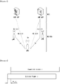
- FIG. 2 illustrates a relationship between a UL frame and a DL frame in a wireless communication system to which a method described in the present disclosure may be implemented.
- slots are numbered in ascending order of n s ⁇ ⁇ 0 , ... , N subframe slots , ⁇ ⁇ 1 in a subframe, and in ascending order of n s , f ⁇ ⁇ 0 , ... , N frame slots , ⁇ ⁇ 1 in a radio frame.
- One slot is composed of continuous OFDM symbols of N symb ⁇ , and N symb ⁇ is determined depending on a numerology in use and slot configuration.
- the start of slots n s ⁇ in a subframe is temporally aligned with the start of OFDM symbols n s ⁇ N symb ⁇ in the same subframe.
- Not all UEs are able to transmit and receive at the same time, and this means that not all OFDM symbols in a DL slot or an UL slot are available to be used.
- Table 2 shows the number of OFDM symbols per slot for a normal CP in the numerology ⁇
- Table 3 shows the number of OFDM symbols per slot for an extended CP in the numerology ⁇ .
- [Table 2] ⁇ Slot Configuration 0 1 N symb ⁇ N frame slots , ⁇ N subframe slots , ⁇ N symb ⁇ N frame slots , ⁇ N subframe slots , ⁇ 0 14 10 1 7 20 2 1 14 20 2 7 40 4 2 14 40 4 7 80 8 3 14 80 8 - - - 4 14 160 16 - - - 5 14 320 32 - - - [Table 3] ⁇ Slot Configuration 0 1 N symb ⁇ N frame slots , ⁇ N subframe slots , ⁇ N symb ⁇ N frame slots , ⁇ N subframe slots , ⁇ 0 12 10 1 6 20 2 1 12 20 2 6 40 4 2 12 40 4 6 80 8 3 12 80 8 - - - 4 12
- an antenna port a resource grid, a resource element, a resource block, a carrier part, etc. may be considered.
- the antenna port is defined such that a channel over which a symbol on one antenna port is transmitted can be inferred from another channel over which a symbol on the same antenna port is transmitted.
- the two antenna ports may be in a QC/QCL (quasi co-located or quasi co-location) relationship.
- the large-scale properties may include at least one of delay spread, Doppler spread, Doppler shift, average gain, and average delay.
- FIG. 3 illustrates an example of a resource grid supported in a wireless communication system to which a method described in the present disclosure may be implemented.
- a resource grid is composed of N RB ⁇ N sc RB subcarriers in a frequency domain, each subframe composed of 14 ⁇ 2 ⁇ OFDM symbols, but the present disclosure is not limited thereto.
- a transmitted signal is described by one or more resource grids, composed of N RB ⁇ N sc RB subcarriers, and 2 ⁇ N symb ⁇ OFDM symbols
- N RB ⁇ ⁇ N RB max , ⁇ indicates the maximum transmission bandwidth, and it may change not just between numerologies, but between UL and DL.
- one resource grid may be configured per the numerology ⁇ and an antenna port p.
- FIG. 4 illustrates examples of a resource grid per antenna port and numerology to which a method described in the present disclosure is applicable.
- the resource element ( k , l ) for the numerology ⁇ and the antenna port p corresponds to a complex value a k , l ⁇ p ⁇ .
- the indexes p and ⁇ may be dropped, and as a result, the complex value may be a k , l ⁇ p or a k , l .
- a relation between a physical resource block number n PRB on the frequency domain and the resource elements ( k , l ) is given by Equation 1.
- n PRB ⁇ k N sc RB ⁇
- a UE may be configured to receive or transmit the carrier part using only a subset of the resource grid.
- a set of resource blocks which the UE is configured to receive or transmit are numbered from 0 to N URB ⁇ ⁇ 1 on the frequency domain.
- FIG. 5 illustrates an example of a self-contained slot structure to which a method described in the present disclosure is applicable.
- a hatched portion 510 denotes a downlink control region
- a black portion 520 denotes an uplink control region
- Such a structure may be characterized in that DL transmission and UL transmission are sequentially performed in one slot, DL data is sent in one slot, and UL Ack/Nack is also transmitted and received in one slot.
- Such a slot may be defined as a 'self-contained slot'.
- the base station reduces the time it takes to retransmit data to the UE when a data transmission error occurs, and thus can minimize latency of final data transfer.
- the base station and the UE require a time gap in a process for switching from a transmission mode to a reception mode or a process for switching from the reception mode to the transmission mode.
- some OFDM symbols at time of switching from DL to UL are configured as a guard period (GP).
- a communication environment to be considered includes all multi-carrier supporting environments. That is, a multi-carrier system or a carrier aggregation (CA) system used in the present disclosure refers to a system that aggregates and uses one or more component carriers (CCs) with a bandwidth less than a target band when configuring a target wideband, in order to support a wideband.
- CA carrier aggregation
- multi-carrier means aggregation of carriers (or carrier aggregation).
- the aggregation of carriers means both aggregation between continuous carriers and aggregation between non-contiguous carriers.
- the number of component carriers aggregated between downlink and uplink may be differently set.
- a case where the number of downlink component carriers (hereinafter referred to as "DL CC") and the number of uplink component carriers (hereinafter, referred to as "UL CC”) are the same is referred to as “symmetric aggregation”
- asymmetric aggregation a case where the number of downlink component carriers and the number of uplink component carriers are different is referred to as "asymmetric aggregation”.
- the carrier aggregation may be used interchangeably with a term such as bandwidth aggregation or spectrum aggregation.
- Carrier aggregation configured by combining two or more component carriers aims at supporting up to a bandwidth of 100 MHz in the LTE-A system.
- a bandwidth of the combined carriers may be limited to a bandwidth used in an existing system in order to maintain backward compatibility with the existing IMT system.
- the existing 3GPP LTE system supports bandwidths of ⁇ 1.4, 3, 5, 10, 15, 20 ⁇ MHz
- a 3GPP LTE-advanced (i.e., LTE-A) system may be configured to support a bandwidth greater than 20 MHz by using only the bandwidths for compatibility with the existing system.
- the carrier aggregation system used in the preset disclosure may be configured to support the carrier aggregation by defining a new bandwidth regardless of the bandwidth used in the existing system.
- the LTE-A system uses a concept of a cell to manage radio resources.
- An environment of the carrier aggregation may be called a multi-cell environment.
- the cell is defined as a combination of a pair of a downlink resource (DL CC) and an uplink resource (UL CC), but the uplink resource is not essential. Therefore, the cell may consist of only the downlink resource or both the downlink resource and the uplink resource.
- DL CC downlink resource
- UL CC uplink resource
- the cell may consist of only the downlink resource or both the downlink resource and the uplink resource.
- the cell may have one DL CC and one UL CC. However, if the specific UE has two or more configured serving cells, the cells have DL CCs as many as the cells, and the number of UL CCs may be equal to or less than the number of DL CCs.
- the DL CC and the UL CC may be configured. That is, when the specific UE has multiple configured serving cells, a carrier aggregation environment, in which the number of UL CCs is more than the number of DL CCs, may also be supported. That is, the carrier aggregation may be understood as aggregation of two or more cells each having a different carrier frequency (center frequency).
- the 'cell' described here should be distinguished from a 'cell' as a region which is generally used and is covered by the base station.
- the cell used in the LTE-A system includes a primary cell (PCell) and a secondary cell (SCell).
- the PCell and the SCell may be used as a serving cell.
- the UE which is in an RRC_CONNECTED state but does not have the configured carrier aggregation or does not support the carrier aggregation, only one serving cell consisting of only the PCell exists.
- the UE which is in the RRC_CONNECTED state and has the configured carrier aggregation one or more serving cells may exist, and the PCell and one or more SCells are included in all serving cells.
- the serving cell may be configured through an RRC parameter.
- PhysCellId as a physical layer identifier of the cell has integer values of 0 to 503.
- SCellIndex as a short identifier used to identify the SCell has integer values of 1 to 7.
- ServCellIndex as a short identifier used to identify the serving cell (PCell or SCell) has integer values of 0 to 7. The value of 0 is applied to the PCell, and SCellIndex is previously given for applying to the SCell. That is, a cell having a smallest cell ID (or cell index) in ServCellIndex is the PCell.
- the PCell means a cell that operates on a primary frequency (or primary CC).
- the PCell may be used for the UE to perform an initial connection establishment process or a connection re-establishment process and may be designated as a cell indicated in a handover process.
- the PCell means a cell which is the center of control-related communication among serving cells configured in the carrier aggregation environment. That is, the UE may be allocated and transmit a PUCCH only in a PCell of the corresponding UE and use only the PCell to acquire system information or change a monitoring procedure.
- An evolved universal terrestrial radio access may change only the PCell for the handover procedure to the UE supporting the carrier aggregation environment by using an RRC connection reconfiguration message RRCConnectionReconfigutaion of higher layer including mobile control information mobilityControlInfo.
- the SCell may mean a cell that operates on a secondary frequency (or secondary CC). Only one PCell may be allocated to a specific UE, and one or more SCells may be allocated to the specific UE.
- the SCell can be configured after RRC connection establishment is achieved and used to provide an additional radio resource.
- the PUCCH does not exist in residual cells, i.e., the SCells excluding the PCell from the serving cells configured in the carrier aggregation environment.
- the E-UTRAN may provide all system information related to an operation of a related cell, which is in an RRC_CONNECTED state, through a dedicated signal when adding the SCells to the UE that supports the carrier aggregation environment.
- a change of the system information may be controlled by releasing and adding the related SCell, and in this case, the RRC connection reconfiguration message RRCConnectionReconfigutaion of higher layer may be used.
- the E-UTRAN may perform dedicated signaling having a different parameter for each UE rather than broadcasting in the related SCell.
- the E-UTRAN can add the SCells to the initially configured PCell in the connection establishment process to configure a network including one or more SCells.
- the PCell and the SCell may operate as the respective component carriers.
- a primary component carrier (PCC) may be used as the same meaning as the PCell
- SCC secondary component carrier
- FIG. 6 illustrates an example of component carriers and carrier aggregation in a wireless communication system to which the present disclosure is applicable.
- FIG. 6(a) illustrates a single carrier structure used in the LTE system.
- a component carrier includes a DL CC and an UL CC.
- One component carrier may have a frequency range of 20 MHz.
- FIG. 6(b) illustrates a carrier aggregation structure used in the LTE-A system. More specifically, FIG. 6(b) illustrates that three component carriers having a frequency magnitude of 20 MHz are combined. Three DL CCs and three UL CCs are provided, but the number of DL CCs and the number of UL CCs are not limited. In the case of carrier aggregation, the UE may simultaneously monitor three CCs, receive downlink signal/data, and transmit uplink signal/data.
- the network may allocate M (M ⁇ N) DL CCs to the UE. In this instance, the UE may monitor only M limited DL CCs and receive the DL signal. Further, the network may prioritize L (L ⁇ M ⁇ N) DL CCs and allocate a primary DL CC to the UE. In this case, the UE has to monitor the L DL CCs. Such a scheme may be equally applied to uplink transmission.
- a linkage between a carrier frequency of a downlink resource (or DL CC) and a carrier frequency of an uplink resource (or UL CC) may be indicated by a higher layer message, such as a RRC message, or system information.
- a higher layer message such as a RRC message
- system information such as system information block type 2 (SIB2).
- the linkage may mean a mapping relation between the DL CC, on which a PDCCH carrying a UL grant is transmitted, and the UL CC using the UL grant, and mean a mapping relation between the DL CC (or UL CC) on which data for HARQ is transmitted and the UL CC (or DL CC) on which HARQ ACK/NACK signal is transmitted.
- the network may activate or deactivate the configured SCell(s).
- the PCell is always activated.
- the network activates or deactivates the SCell(s) by sending an activation/deactivation MAC control element.
- the activation/deactivation MAC control element has a fixed size and consists of a single octet including seven C-fields and one R-field.
- the C-field is configured for each SCell index (SCellIndex), and indicates the activation/deactivation state of the SCell. If a value of the C-field is set to '1', it indicates that a SCell having a corresponding SCell index is activated. If a value of the C-field is set to '0', it indicates that a SCell having a corresponding SCell index is deactivated.
- the UE maintains a timer sCellDeactivationTimer per configured SCell and deactivates the associated SCell when the timer expires.
- the same initial timer value is applied to each instance of the timer sCellDeactivationTimer and is configured by RRC signaling.
- initial SCell(s) are in a deactivation state.
- the UE performs the following operation on each of the configured SCell(s) in each TTI.
- carrier aggregation has been described based on the LTE/LTE-A system, but it is for convenience of description and can be equally or similarly extended and applied to the 5G NR system.
- carrier aggregation deployment scenarios that may be considered in the 5G NR system may be the same as FIG. 7 .
- FIG. 7 illustrates examples of deployment scenarios considering carrier aggregation in a NR system.
- F1 and F2 may respectively mean a cell configured to a first frequency (or a first frequency band, a first carrier frequency, a first center frequency) and a cell configured as a second frequency (or a second frequency band, a second carrier frequency or a second center frequency).
- FIG. 7(a) illustrates a first CA deployment scenario.
- the F1 cell and the F2 cell may be co-located and overlaid. In this case, both the two layers can provide sufficient coverage, and mobility can be supported on the two layers.
- the first CA deployment scenario may include a case where the F1 cell and the F2 cell are present in the same band. In the first CA deployment scenario, it may be expected that aggregation is possible between the overlaid F1 and F2 cells.
- FIG. 7(b) illustrates a second CA deployment scenario.
- the F1 cell and the F2 cell may be co-located and overlaid, but the F2 cell may support smaller coverage due to a larger path loss. In this case, only the F1 cell provides sufficient coverage, and the F2 cell may be used to improve throughput. In this instance, mobility may be performed based on the coverage of the F1 cell.
- the second CA deployment scenario may include a case where the F1 cell and the F2 cell are present in different bands (e.g., the F1 cell is present in ⁇ 800 MHz, 2 GHz ⁇ and the F2 cell is present in ⁇ 3.5 GHz ⁇ ). In the second CA deployment scenario, it may be expected that aggregation is possible between the overlaid F1 and F2 cells.
- FIG. 7(c) illustrates a third CA deployment scenario.
- the F1 cell and the F2 cell are co-located and overlaid, but antennas of the F2 cell may be directed to boundaries of the F2 cell so that cell edge throughput is increased.
- the F1 cell provides sufficient coverage, but the F2 cell may potentially have holes due to a larger path loss.
- mobility may be performed based on the coverage of the F1 cell.
- the third CA deployment scenario may include a case where the F1 cell and the F2 cell are present in different bands (e.g., the F1 cell is present in ⁇ 800 MHz, 2 GHz ⁇ and the F2 cell is present in ⁇ 3.5 GHz ⁇ ).
- the F1 and F2 cells of the same base station e.g., eNB
- FIG. 7(d) illustrates a fourth CA deployment scenario.
- the F1 cell provides macro coverage
- F2 remote radio heads (RRHs) may be used to improve throughput at hot spots.
- mobility may be performed based on the coverage of the F1 cell.
- the fourth CA deployment scenario may include both a case where the F1 cell and the F2 cell correspond to DL non-contiguous carriers on the same band (e.g., 1.7 GHz) and a case where the F1 cell and the F2 cell are present on different bands (e.g., the F1 cell is present in ⁇ 800 MHz, 2 GHz ⁇ and the F2 cell is present in ⁇ 3.5 GHz ⁇ ).
- the F2 cells i.e., RRHs
- FIG. 7(e) illustrates a fifth CA deployment scenario.
- the fifth CA deployment scenario is similar to the second CA deployment scenario, but frequency selective repeaters may be deployed so that coverage can be extended for one of the carrier frequencies.
- it may be expected that the F1 and F2 cells of the same base station can be aggregated in a region where coverage overlaps.
- a reception timing difference at the physical layer of UL grants and DL assignments for the same TTI (e.g., depending on the number of control symbols, propagation and deployment scenario) although it is caused by different serving cells may not affect a MAC operation.
- the UE may need to cope with a relative propagation delay difference of up to 30 us among the CCs to be aggregated in both intra-band non-contiguous CA and inter-band non-contiguous CS. This may mean that the UE needs to cope with a delay spread of up to 30.26 us among the CCs monitored at a receiver because a time alignment of the base station is specified to be up to 0.26 us. This may also mean that the UE have to cope with a maximum uplink transmission timing difference between TAGs of 36.37 us for inter-band CA with multiple TAGs.
- a frame timing and a system frame number (SFN) may be aligned across aggregated cells.
- Table 4 represents an example of a PRACH format supported in current LTE.
- a maximum cell radius supported in the current LTE is 100.2 km.
- a cell radius support of at least the same level is necessary for an in-band operation using a LTE network.
- the LTE supports a 4-step contention-based RACH procedure as follows.
- An operation after the Msg4 proceeds with transmission of a RRC connection setup complete message including HARQ-ACK and UE ID for the Msg4.
- a new radio supports various numerologies for each component carrier (CC) considering use case scenarios (eMBB, mMTC, URLLC, V2X) considered in a NR system and deployments in various frequency bands.
- the numerology refers to a subcarrier spacing (SCS) and a cyclic prefix CP).
- the present disclosure provides a method for supporting a timing adjustment (TA) in a NR carrier aggregation (CA) situation where the numerology may be different for each CC and/or between CCs.
- TA timing adjustment
- CA NR carrier aggregation
- 'A and/or B' used in the present disclosure may be interpreted as the same meaning as 'including at least one of A or B'.
- the TA may be expressed as a time adjustment or a timing advance.
- the timing advance refers to a timing offset that the UE applies upon the uplink transmission, for the purpose of orthogonal uplink/downlink transmission/reception at a base station (e.g., eNB), i.e., in order to adjust synchronization of an uplink slot (or subframe) and a downlink slot (or subframe).
- a base station e.g., eNB
- the NR can configure multiple timing advance groups (TAGs), i.e., multiple TAGs to support CA deployment scenario 4 (HetNet), etc. of FIG. 7 , apply a different TA for each TAG, and perform the uplink transmission.
- TAGs timing advance groups
- HetNet CA deployment scenario 4
- the TAG may include at least one cell (or CC).
- a TAG including the PCell among the TAGs is expressed as a pTAG, and a TAG consisting of only SCell is expressed as a sTAG.
- Initial timing information about an initial pTAG is acquired through a random access (RA) procedure.
- RA random access
- timing information about the sTAG may be acquired through a contention-free RA procedure in a narrowband PDCCH (NPDCCH) order in a RRC-CONNECTED state.
- NPDCCH narrowband PDCCH
- the present disclosure provides a method of determining various requirements, TA granularity, and a TA maximum value for supporting a TA or multiple TAs in the NR CA.
- a first embodiment relates to a method of determining a max DL receive timing difference requirement. This embodiment is not part of the invention.
- a receive timing difference between downlink CCs in NR CA affects a receive buffer, latency, a max TA of a UE, and the like.
- the max TA means a maximum value of the TA.
- the first embodiment describes a method of determining the max DL receive timing difference requirement for the purpose of a reduction in a receiver buffer size burden and latency, or considering the max TA.
- the max DL receive timing difference requirement may be determined based on the following various methods (Methods 1 to 3).
- Method 1 is a method of determining the max DL receive timing difference requirement considering receive buffer requirements.
- the UE may have a burden of buffering data before processing control data.
- the max DL receive timing difference requirement can be determined based on a DL receive buffer size.
- CP overhead is the same and receive bandwidth of the UE is the same
- data received from CC2 has the same transfer data rate regardless of a subcarrier spacing (SCS).
- SCS subcarrier spacing
- the DL receive buffer requirement is the same regardless of the SCS.
- DL receive buffer requirements of the receiver may be differently configured because an effective data rate except the CP is different.
- an actual DL receive buffer requirement of the UE is reduced because a CP overload of the extended CP is greater than that of a normal CP.
- the method may determine each max DL receive timing difference requirement that can be supported within a limit of each DL receive buffer size, and use a max DL receive timing difference requirement corresponding to the max DL receive timing difference requirement determined depending on the UE capability.
- the method may stipulate a minimum requirement of the DL receive buffer size, determine a max DL receive timing difference requirement as a maximum DL receive timing difference value that can be supported by a DL receive buffer corresponding to the minimum requirement, and commonly use it for the UE.
- the max DL receive timing difference requirement may be determined based on a minimum value of the DL receive buffer requirement supporting within one or multiple TAG(s), and the corresponding value may be commonly used for the UE.
- the DL receive bandwidth should be considered when determining the max DL receive timing difference requirement.
- the DL receive buffer requirement is also increased N times.
- the max DL receive timing difference requirement can be determined as follows, considering the DL receive buffer size, and/or DL receive bandwidth X and/or CP overhead.
- the DL receive bandwidth may mean a maximum DL receive bandwidth supported in the UE or a maximum receive bandwidth supported in a corresponding CC or the like for convenience of operation.
- the DL receive buffer size may mean a minimum DL receive buffer size or a minimum DL receive buffer requirement or the like that can be configured in a corresponding CC.
- the normal CP can support the smaller max DL receive timing difference than the extended CP under the same DL receive buffer size.
- the max DL receive timing difference can be determined based on the normal CP.
- Method 2 is a method of determining the max DL receive timing difference requirement considering latency requirements.
- a time from a downlink control reception time to a data decoding complete time may be delayed.
- the max DL receive timing difference requirement may be limited for services, in which latency is important, due to the latency requirements.
- Method 3 is a method of determining the max DL receive timing difference requirement considering max TA requirement.
- the UE After the reception of downlink control, the UE performs the operation such as uplink transmission after downlink control decoding, uplink data preparation, or downlink data decoding (HARQ-ACK preparation if necessary).
- the operation such as uplink transmission after downlink control decoding, uplink data preparation, or downlink data decoding (HARQ-ACK preparation if necessary).
- the UE Upon the uplink transmission, the UE applies the TA.
- the max DL receive timing difference may be limited.
- a second embodiment relates to a method of determining a max UL transmit timing difference requirement.
- the NR may configure multiple TAGs to support CA deployment scenario 4 (HetNet), etc., apply a different TA for each TAG, and perform the uplink transmission.
- HetNet CA deployment scenario 4
- An effect of the power allocation problem due to the UL transmit timing difference is more serious when a slot length is short under a given UL transmit timing difference (e.g., when SCS is large).
- the slot length is 1/N as the SCS increases N times
- a ratio affected by the power allocation problem within the slot is increased N times.
- Method 1 is to configure a max UL transmit timing difference requirement based on max SCS.
- the method can allow the max UL transmit timing difference requirement to be configured based on the max SCS.
- a value of the max UL transmit timing difference requirement configured for each max SCS may be a value that has an inverse proportional relationship with a magnitude of the max SCS.
- a value of the max UL transmit timing difference requirement may be 1/N times of a value of the max UL transmit timing difference requirement when the max SCS is 15 kHz.
- the max SCS may be a maximum value among all of SCS values supported in a corresponding system or a frequency band or a center frequency or a TAG or a CC.
- a relation between the value of the max UL transmit timing difference requirement and the (max) SCS may be described in the form of a table in the standard document, and in this case, the above descriptions may be applied.
- the max SCS supported in the TAG or the CC may be a configured TAG or CC or an activated TAG or CC that actually performs UL transmission.
- Method 2 is to determine a max UL transmit timing difference requirement by means of a fixed specific value.
- the Method 2 uses a fixed value as the max UL transmit timing difference requirement regardless of SCS.
- the max UL transmit timing difference requirement is determined based on a specific SCS (e.g., based on 15 kHz SCS), and is applied regardless of numerology actually using it.
- the Method 2 may be applied when the effect of the power allocation problem within the slot does not need to be maintained at a certain ratio.
- one TB can be transmitted uniformly across N slots, and the UE can again gather and decode one TB transmitted across multiple slots.
- the Method 2 does not need to maintain the effect of the power allocation problem within the slot at a certain ratio, as in the Method 1 described above.
- Examples of the case in which one TB is transmitted uniformly across N slots may include a slot aggregation or a multi-slot scheduling.
- Method 3 is to select one of the Method 1 or the Method 2 according to a scheduling method.
- the Method 3 may determine the Method 1 or the Method 2 depending on whether there is the slot aggregation or the multi-slot scheduling.
- the Method 1 may be determined. Otherwise, the Method 2 may be determined.
- the slot aggregation or the multi-slot scheduling may be configured in line with the Method 1 or the Method 2.
- Method 1 For example, if the Method 1 is configured, all of a single-slot scheduling and the slot aggregation or the multi-slot scheduling can be selected.
- Method 2 may be limited to select only the slot aggregation or the multi-slot scheduling because a specific slot may be greatly affected by the power allocation problem.
- the single-slot scheduling refers to a general case in which one TB is transmitted in one slot.
- the slot aggregation or the multi-slot scheduling refers to another method in which one TB is transmitted uniformly across N slots.
- the corresponding fixed value may be a fixed value that is pre-defined in the standard document, or a value that is RRC-configured in advance.
- a third embodiment relates to a method of determining TA granularity.
- TA granularity is fixed to 16Ts.
- a length of LTE normal CP is 144Ts (or 160Ts)
- about two TA adjustment units may exist in the CP.
- the adjustment for the TA granularity is necessary in the NR.
- the TA granularity may be determined based on the following methods depending on a single TAG and multiple TAGs.
- Method 1 It is a case where a TAG consists of a single numerology.
- a value of the TA granularity configured for each SCS may be inversely proportional to the SCS.
- the TA granularity may be configured to scale down to 1/N times compared to the TA granularity of 15 kHz.
- Method 2 It is a case where the TAG consists of a mixed numerology.
- the TA granularity may be configured based on a max SCS in the TAG.
- the TA granularity may be configured based on a max SCS among them.
- the TA granularity may be configured to scale down to 1/N times compared to the TA granularity of 15 kHz.
- Method 1 It is a case where each TAG consists of a single numerology.
- the TA granularity may be configured for each SCS of each TAG.
- TA granularity corresponding to the corresponding SCS may be configured for each TAG.
- Method 1 may be used as a method of configuring the TA granularity for each TAG.
- the TA granularity may be configured based on a max SCS in multiple TAGs.
- the TA granularity may be configured based on a maximum value (i.e., max SCS) among SCSs constituting each TAG for the purpose of common TA granularity application.
- the TA granularity may be configured to scale down to 1/N times compared to the TA granularity of 15 kHz.
- the TA granularity may be configured based on a max SCS of each TAG.
- the TA granularity may be configured based on a max SCS of each TAG.
- a method of configuring the TA granularity based on a max SCS of each TAG may use the (Method 2) for the single TAG.
- the TA granularity may be configured based on a max SCS in multiple TAGs.
- the TA granularity may be configured based on a maximum value (i.e., max SCS) among SCSs constituting each TAG for the purpose of common application of the TA granularity.
- the corresponding fixed max TA value or TA granularity value may be a fixed value that is pre-defined in the standard document, or a value that is RRC-configured in advance.
- the TAG consists of the single numerology, the following three methods are described as the max TA determination method.
- Method 1 It is a method of configuring the max TA for each SCS.
- the max TA configured for each SCS may be a value that is configured to have an inverse proportional relationship with the SCS.
- MAC RAR and MAC CE TA command bit size may increase or decrease.
- the TA granularity may be a value configured to have an inverse proportional relationship with the SCS in the same method as the max TA.
- Method 2 It is a method in which the max TA is fixed.
- This method configures the max TA value as a fixed value regardless of the SCS constituting the TAG.
- the fixed value may be a value fixed to the same max TA as LTE in order to support the same max TA as the existing LTE.
- the TA granularity may be used as a fixed value together with the max TA.
- the fixed value may be a value set based on the configurable max SCS.
- the max TA is fixed, and the TA granularity may apply the method of determining the TA granularity for each SCS described above and may use a different configuration value depending on the SCS.
- the MAC RAR TA command bit size may increase or decrease depending on the SCS.
- the max TA is fixed, and the TA granularity is reduced to 1/N times.
- the MAC RAR TA command bit size can be extended to log2(N) bit.
- Method 3 It is a method in which a hybrid max TA is configured.
- This method configures a max TA required for an initial TA to a fixed value in this case and allows the max TA to have the LTE level max TA.
- this method can differently configure the max TA in a TA tracking situation for each max SCS, and thus efficiently manage MAC CE.
- the max TA in the TA tracking situation may be a value considering the SCS and/or the CP.
- the max TA may be a value configured to have an inverse proportional relationship with the SCS.
- the TAG consists of the mixed numerology, the following three methods are described as the max TA determination method.
- Method 1 It is a method in which the max TA is configured based on a min SCS in the TAG.
- This method configures the max TA based on a min SCS among multiple SCSs constituting the TAG.
- this method supports at least LTE level max TA.
- min SCS exceeds 15 kHz, a configured max TA value is applied for the min SCS.
- the max TA values applied for each min SCS may be values configured to have an inverse proportional relationship with the SCS. For example, if the SCS is N times 15 kHz, the max TA may be configured to be 1/N times compared to the max TA of 15 kHz.
- Method 2 It is a method in which the max TA is fixed.
- This method is a method of configuring a fixed max TA value regardless of SCSs constituting the TAG.
- the fixed max TA value may be the same max TA value as the existing LTE, or a max TA value that is newly defined in NR.
- Method 3 It is a method in which the max TA is configured based on a max SCS in the TAG.
- This method is a method of configuring the max TA based on a max SCS among multiple SCSs constituting the TAG. If the TAG consists of a mixed numerology in NR, a method of configuring TA granularity based on a max SCS among them is described.
- the TA granularity is configured to scale down to 1/N times compared to the TA granularity of 15 kHz.
- the max TA may be configured based on the max SCS.
- the MAC CE TA command bit size is equally maintained regardless of the max SCS value, and an integer value of a TA command expressed by the same bit size becomes the form of being scaled and interpreted depending on the max SCS value.
- the integer value of the TA command may be multiplied by 1/N and may be the form of applying as an actual TA value.
- the corresponding fixed max TA value or TA granularity value may be a fixed value that is pre-defined in the standard document, or a value that is RRC-configured in advance.
- a fifth embodiment is to configure a restriction on DL buffering and UL power control mentioned above. This embodiment is not part of the invention.
- a max DL receive timing difference may be restricted by a UE DL receive buffer size.
- a supportable max DL receive timing difference is extended, and thus there may be many combinations of CCs capable of DL CA.
- the DL receive buffer size may be reported to the eNB in the form of UE capability, or may be a minimum DL receive buffer size that all the UEs should mandatorily have in order to meet a max DL receiver timing difference requirement.
- the max DL receive timing difference may be restricted by a UE DL receive bandwidth.
- the UE DL receive bandwidth may be a configured DL bandwidth, or an activated DL bandwidth receiving actual DA data, or a maximum DL bandwidth provided by a corresponding frequency band, or a maximum DL bandwidth that the UE is able to receive.
- a max UL transmit timing difference may be restricted because of the power allocation problem mentioned above, and a supportable max UL transmit timing difference decreases as the max SCS increases.
- combinations of CCs capable of UL CA may be restricted.
- the following restriction may be considered.
- the sTAG When one of the UL transmissions has to drop, the sTAG first drops if it is UL CA for a pTAG and a sTAG.
- a drop order may be determined according to order of TAG ID.
- a TAG having a large TAG ID value may first drop.
- the supportable max UL transmit timing difference may be a value configured for each max SCS or a fixed value regardless of the max SCS.
- the X value of the above restriction may be a value changed for each max SCS.
- the X value may be a value that has an inverse proportional relationship with the max SCS.
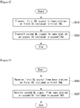
- FIG. 8 illustrates an example of an operation of a user equipment (UE) transmitting an uplink signal in a CA situation described in the present disclosure.
- UE user equipment
- a UE transmits a first uplink signal to a base station on a first component carrier included in a first timing advance group (TAG) in S810.
- TAG timing advance group
- the UE transmits a second uplink signal to the base station on a second component carrier included in a second TAG in S820.
- the first TAG and the second TAG apply different timing advances (TAs).
- a maximum uplink timing difference between the first uplink signal and the second uplink signal is determined based on a maximum subcarrier spacing.
- the maximum uplink timing difference may be reduced to 1/N times.
- the maximum subcarrier spacing may be set to a maximum value among subcarrier spacings supported in a specific frequency band, a wireless communication system or a TAG.
- a TA granularity for the first TAG and the second TAG is configured based on the maximum subcarrier spacing.
- Each of the first TAG and the second TAG may be configured with a single numerology or multiple numerologies.
- a maximum TA may be configured for each subcarrier spacing.
- a maximum TA in each TAG is configured based on a minimum subcarrier spacing.
- the first TAG may be a primary TAG (pTAG)
- the second TAG may be a secondary TAG (sTAG).
- FIG. 9 illustrates an example of an operation of a UE receiving a downlink signal in a CA situation described in the present disclosure. This example is not part of the invention.
- a UE receives a first downlink signal from a base station on a first component carrier included in a first timing advance group (TAG) in S910.
- TAG timing advance group
- the UE receives a second downlink signal from the base station on a second component carrier included in a second TAG in S920.
- a maximum uplink timing difference between the first downlink signal and the second downlink signal may be determined based on at least one of a receive buffer size, a latency or a maximum TA.
- the first downlink signal may be a downlink control signal
- the second downlink signal may be downlink data.
- FIG. 10 illustrates a block configuration diagram of a wireless communication device to which methods described in the present disclosure are applicable.
- a wireless communication system includes a base station 1010 and multiple UEs 1020 located in a region of the base station.
- Each of the base station 1010 and the UE 1020 may be represented as a radio device.
- the base station 1010 includes a processor 1011, a memory 1012, and a radio frequency (RF) module 1013.
- the processor 1011 implements functions, processes, and/or methods described in FIGS. 1 to 9 . Layers of radio interface protocol may be implemented by the processor 1011.
- the memory 1012 is connected to the processor 1011 and stores various types of information for driving the processor 1011.
- the RF module 1013 is connected to the processor 1011 and transmits and/or receives radio signals.
- the UE 1020 includes a processor 1021, a memory 1022, and a RF module 1023.
- the processor 1021 implements functions, processes, and/or methods described in FIGS. 1 to 9 .
- Layers of radio interface protocol may be implemented by the processor 1021.
- the memory 1022 is connected to the processor 1021 and stores various types of information for driving the processor 1021.
- the RF module 1023 is connected to the processor 1021 and transmits and/or receives radio signals.
- the memories 1012 and 1022 may be inside or outside the processors 1011 and 1021 and may be connected to the processors 1011 and 1021 through various well-known means.
- the base station 1010 and/or the UE 1020 may have a single antenna or multiple antennas.
- FIG. 11 illustrates a block configuration diagram of a communication device according to an embodiment of the present disclosure.
- FIG. 11 illustrates in more detail the UE illustrated in FIG. 10 .
- the UE may include a processor (or digital signal processor (DSP)) 1110, an RF module (or RF unit) 1135, a power management module 1105, an antenna 1140, a battery 1155, a display 1115, a keypad 1120, a memory 1130, a subscriber identification module (SIM) card 1125 (which is optional), a speaker 1145, and a microphone 1150.
- the UE may also include a single antenna or multiple antennas.
- the processor 1110 implements functions, processes, and/or methods described in FIGS. 1 to 9 . Layers of a radio interface protocol may be implemented by the processor 1110.
- the memory 1130 is connected to the processor 1110 and stores information related to operations of the processor 1110.
- the memory 1130 may be inside or outside the processor 1110 and may be connected to the processors 1110 through various well-known means.
- a user inputs instructional information, such as a telephone number, for example, by pushing (or touching) buttons of the keypad 1120 or by voice activation using the microphone 1150.
- the processor 1110 receives and processes the instructional information to perform an appropriate function, such as to dial the telephone number.
- Operational data may be extracted from the SIM card 1125 or the memory 1130. Further, the processor 1110 may display instructional information or operational information on the display 1115 for the user's reference and convenience.
- the RF module 1135 is connected to the processor 1110 and transmits and/or receives a RF signal.
- the processor 1110 forwards instructional information to the RF module 1135 in order to initiate communication, for example, transmit a radio signal configuring voice communication data.
- the RF module 1135 consists of a receiver and a transmitter to receive and transmit the radio signal.
- the antenna 1140 functions to transmit and receive the radio signal.
- the RF module 1135 may forward a signal to be processed by the processor 1110 and convert the signal into a baseband.
- the processed signal may be converted into audible or readable information output via the speaker 1145.
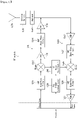
- FIG. 12 illustrates an example of a RF module of a wireless communication device to which a method described in the present disclosure is applicable.
- FIG. 12 illustrates an example of an RF module that can be implemented in a frequency division duplex (FDD) system.
- FDD frequency division duplex
- the processor described in FIGS. 10 and 11 processes data to be transmitted and provides an analog output signal to a transmitter 1210.
- the analog output signal is filtered by a low pass filter (LPF) 1211 to remove images caused by a digital-to-analog conversion (ADC), is up-converted from a baseband to an RF by an up-converter (mixer) 1212, and is amplified by a variable gain amplifier (VGA) 1213.
- the amplified signal is filtered by a filter 1214, is additionally amplified by a power amplifier (PA) 1215, is routed through duplexer(s) 1250/antenna switch(es) 1260, and is transmitted through an antenna 1270.
- LPF low pass filter
- ADC digital-to-analog conversion
- VGA variable gain amplifier
- the antenna 1270 receives signals from the outside and provides the received signals, and the signals are routed through the antenna switch(es) 1260/duplexers 1250 and are provided to a receiver 1220.
- the received signals are amplified by a low noise amplifier (LNA) 1223, are filtered by a bans pass filter 1224, and are down-converted from the RF to the baseband by a down-converter (mixer) 1225.
- LNA low noise amplifier
- Mixer down-converter
- the down-converted signal is filtered by a low pass filter (LPF) 1226 and is amplified by a VGA 1227 to obtain an analog input signal, and the analog input signal is provided to the processor described in FIGS. 10 and 11 .
- LPF low pass filter
- a local oscillator (LO) generator 1240 generates transmitted and received LO signals and provides them to each of the up-converter 1212 and the down-converter 1225.
- LO local oscillator
- phase locked loop (PLL) 1230 receives control information from the processor in order to generate the transmitted and received LO signals at appropriate frequencies and provides control signals to the LO generator 1240.
- PLL phase locked loop
- the circuits illustrated in FIG. 12 may be arranged differently from the configuration illustrated in FIG. 12 .
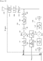
- FIG. 13 illustrates another example of a RF module of a wireless communication device to which a method described in the present disclosure is applicable.
- FIG. 13 illustrates an example of an RF module that can be implemented in a time division duplex (TDD) system.
- TDD time division duplex
- a transmitter 1310 and a receiver 1320 of the RF module in the TDD system have the same structure as the transmitter and the receiver of the RF module in the FDD system.
- a signal amplified by a power amplifier (PA) 1315 of the transmitter 1310 is routed through a band select switch 1350, a band pass filter (BPF) 1360, and antenna switch(es) 1370 and is transmitted via an antenna 1380.
- PA power amplifier
- BPF band pass filter
- the antenna 1380 receives signals from the outside and provides the received signals, and the signals are routed through the antenna switch(es) 1370, the band pass filter 1360, and the band select switch 1350 and are provided to the receiver 1320.
- Embodiments of the present disclosure can be implemented by various means, for example, hardware, firmware, software, or combinations thereof.
- one embodiment of the present disclosure can be implemented by one or more application specific integrated circuits (ASICs), digital signal processors (DSPs), digital signal processing devices (DSPDs), programmable logic devices (PLDs), field programmable gate arrays (FPGAs), processors, controllers, microcontrollers, microprocessors, and the like.
- ASICs application specific integrated circuits
- DSPs digital signal processors
- DSPDs digital signal processing devices
- PLDs programmable logic devices
- FPGAs field programmable gate arrays
- processors controllers, microcontrollers, microprocessors, and the like.
- one embodiment of the present disclosure can be implemented by modules, procedures, functions, etc. performing functions or operations described above.
- Software code can be stored in a memory and can be driven by a processor.
- the memory is provided inside or outside the processor and can exchange data with the processor by various well-known means.
Landscapes
- Engineering & Computer Science (AREA)
- Signal Processing (AREA)
- Computer Networks & Wireless Communication (AREA)
- Mobile Radio Communication Systems (AREA)
Claims (8)
- Procédé d'émission, par un équipement utilisateur (1020), d'un signal de liaison montante en utilisant une agrégation de porteuses dans un système de communication sans fil, le procédé comprenant :l'émission, vers une station de base, BS (1010), d'un premier signal de liaison montante sur une première porteuse composante, CC, comprise dans un premier groupe d'avance temporelle, TAG ; etl'émission, vers la BS (1010), d'un second signal de liaison montante sur une seconde CC comprise dans un second TAG,dans lequel le premier TAG et le second TAG appliquent des avances temporelles, TA, différentes,dans lequel une différence temporelle maximale de liaison montante entre le premier signal de liaison montante et le second signal de liaison montante est déterminée sur la base d'un espacement maximal entre sous-porteuses,caractérisé en ce qu'une granularité de TA pour le premier TAG et le second TAG est configurée sur la base de l'espacement maximal entre sous-porteuses,dans lequel chacun du premier TAG et du second TAG est configuré avec de multiples numérologies,dans lequel, si chacun du premier TAG et du second TAG est configuré avec les multiples numérologies, une TA maximale dans chaque TAG est configurée sur la base d'un espacement minimal entre sous-porteuses.
- Procédé selon la revendication 1, dans lequel, quand l'espacement maximal entre sous-porteuses augmente N fois, la différence temporelle maximale de liaison montante est réduite à 1/N fois.
- Procédé selon la revendication 1, dans lequel l'espacement maximal entre sous-porteuses est fixé à une valeur maximale parmi des espacements entre sous-porteuses pris en charge dans une bande de fréquences spécifique, le système de communication sans fil ou un TAG.
- Procédé selon la revendication 1, dans lequel le premier TAG est un TAG primaire, pTAG, et le second TAG est un TAG secondaire, sTAG.
- Equipement utilisateur, UE (1020), configuré pour émettre un signal de liaison montante en utilisant une agrégation de porteuses dans un système de communication sans fil, l'UE (1020) comprenant :au moins un émetteur-récepteur (1023) configuré pour émettre et recevoir un signal radio ; etau moins un processeur (1021) connecté en fonctionnement à l'au moins un émetteur-récepteur (1023),dans lequel l'au moins un processeur (1021) est configuré pour :émettre, à une station de base, BS (1010) via l'au moins un émetteur-récepteur (1023), un premier signal de liaison montante sur une première porteuse composante, CC, comprise dans un premier groupe d'avance temporelle, TAG ; etémettre, à la BS (1010) via l'au moins un émetteur-récepteur (1023), un second signal de liaison montante sur une seconde CC comprise dans un second TAG,dans lequel le premier TAG et le second TAG appliquent des avances temporelles, TA, différentes,dans lequel une différence temporelle maximale de liaison montante entre le premier signal de liaison montante et le second signal de liaison montante est déterminée sur la base d'un espacement maximal entre sous-porteuses,caractérisé en ce qu'une granularité de TA pour le premier TAG et le second TAG est configurée sur la base de l'espacement maximal entre sous-porteuses,dans lequel chacun du premier TAG et du second TAG est configuré avec de multiples numérologies,dans lequel, si chacun du premier TAG et du second TAG est configuré avec les multiples numérologies, une TA maximale dans chaque TAG est configurée sur la base d'un espacement minimal entre sous-porteuses.
- UE (1020) selon la revendication 5, dans lequel, quand l'espacement maximal entre sous-porteuses augmente N fois, la différence temporelle maximale de liaison montante est réduite à 1/N fois.
- UE (1020) selon la revendication 5, dans lequel l'espacement maximal entre sous-porteuses est fixé à une valeur maximale parmi des espacements entre sous-porteuses pris en charge dans une bande de fréquences spécifique, le système de communication sans fil ou un TAG.
- UE (1020) selon la revendication 5, dans lequel le premier TAG est un TAG primaire, pTAG, et le second TAG est un TAG secondaire, sTAG.
Applications Claiming Priority (2)
| Application Number | Priority Date | Filing Date | Title |
|---|---|---|---|
| US201762556503P | 2017-09-10 | 2017-09-10 | |
| PCT/KR2018/010575 WO2019050370A1 (fr) | 2017-09-10 | 2018-09-10 | Procédé et dispositif d'émission et de réception de signal à l'aide d'agrégation de porteuse dans un système de communication sans fil |
Publications (3)
| Publication Number | Publication Date |
|---|---|
| EP3675576A1 EP3675576A1 (fr) | 2020-07-01 |
| EP3675576A4 EP3675576A4 (fr) | 2020-11-11 |
| EP3675576B1 true EP3675576B1 (fr) | 2022-11-02 |
Family
ID=65635095
Family Applications (1)
| Application Number | Title | Priority Date | Filing Date |
|---|---|---|---|
| EP18853140.4A Active EP3675576B1 (fr) | 2017-09-10 | 2018-09-10 | Procédé et dispositif d'émission et de réception de signal à l'aide d'agrégation de porteuse dans un système de communication sans fil |
Country Status (6)
| Country | Link |
|---|---|
| US (1) | US10917205B2 (fr) |
| EP (1) | EP3675576B1 (fr) |
| JP (1) | JP7041250B2 (fr) |
| KR (2) | KR102370452B1 (fr) |
| CN (1) | CN111066362B (fr) |
| WO (1) | WO2019050370A1 (fr) |
Families Citing this family (10)
| Publication number | Priority date | Publication date | Assignee | Title |
|---|---|---|---|---|
| BR112020008456A2 (pt) * | 2017-10-31 | 2020-11-03 | Ntt Docomo, Inc. | terminal e método de transmissão para um terminal |
| US11665659B2 (en) * | 2017-11-14 | 2023-05-30 | Telefonaktiebolaget Lm Ericsson (Publ) | Method for managing time alignment for uplink transmission between a UE and a network node in a wireless communication network |
| CN113455070B (zh) * | 2019-02-21 | 2024-05-03 | 株式会社Ntt都科摩 | 用户装置以及基站装置 |
| WO2021033114A1 (fr) * | 2019-08-16 | 2021-02-25 | Telefonaktiebolaget Lm Ericsson (Publ) | Amélioration de l'avance temporelle |
| US11606789B2 (en) * | 2019-10-18 | 2023-03-14 | Qualcomm Incorporated | Asynchronous carrier aggregation slot alignment |
| KR20230043793A (ko) * | 2020-07-23 | 2023-03-31 | 인텔 코포레이션 | 물리 다운링크 공유 채널(pdsch) 송신들을 위한 레이트-매칭 자원들 및 상이한 타이밍들을 갖는 업링크 송신들의 멀티플렉싱 |
| CN114258127B (zh) * | 2020-09-25 | 2023-09-15 | 维沃移动通信有限公司 | 信息确定方法、信息发送方法、装置和设备 |
| CN116671213A (zh) * | 2021-01-07 | 2023-08-29 | 华为技术有限公司 | 确定发送功率的方法及装置 |
| US11849428B2 (en) * | 2021-06-21 | 2023-12-19 | AT&T Technical Services Company, Inc. | System and methods for coverage extension based on carrier aggregation |
| WO2023159366A1 (fr) * | 2022-02-23 | 2023-08-31 | Qualcomm Incorporated | Commutation dynamique entre différents minutages d'ul pour mtrp de mdci |
Family Cites Families (9)
| Publication number | Priority date | Publication date | Assignee | Title |
|---|---|---|---|---|
| KR102088021B1 (ko) * | 2011-03-11 | 2020-03-11 | 엘지전자 주식회사 | 반송파 집성 기법이 적용된 무선 통신 시스템에서 단말이 신호를 송수신하는 방법 및 이를 위한 장치 |
| EP2811808A1 (fr) * | 2013-04-01 | 2014-12-10 | Innovative Sonic Corporation | Procédé et appareil pour déclencher un rapport d'état de tampon (BSR) dans une connectivité double |
| US20150327198A1 (en) * | 2014-05-12 | 2015-11-12 | Telefonaktiebolaget L M Ericsson (Publ) | Handling of Cells Associated with Timing Advance Groups in a Wireless Communications System |
| EP3636036B1 (fr) * | 2017-05-05 | 2022-01-19 | Samsung Electronics Co., Ltd. | Appareils et procédés de gestion d'une configuration de canal d'accès aléatoire dans un système de communication sans fil |
| US11240774B2 (en) * | 2017-06-02 | 2022-02-01 | Qualcomm Incorporated | Timing advance group for new radio |
| US20180359149A1 (en) * | 2017-06-08 | 2018-12-13 | Sharp Laboratories Of America, Inc. | Systems and methods for adding and modifying signaling radio bearers and data radio bearers that include numerology (sub-carrier spacing) information |
| US10548126B2 (en) * | 2017-06-16 | 2020-01-28 | Qualcomm Incorporated | Carrier aggregation under different subframe structures in new radio |
| CN116709494A (zh) * | 2017-08-10 | 2023-09-05 | 三星电子株式会社 | 用于确定上行链路发送定时的方法和装置 |
| US11032816B2 (en) * | 2017-08-10 | 2021-06-08 | Qualcomm Incorporated | Techniques and apparatuses for variable timing adjustment granularity |
-
2018
- 2018-09-10 KR KR1020217032531A patent/KR102370452B1/ko active IP Right Grant
- 2018-09-10 CN CN201880058330.2A patent/CN111066362B/zh active Active
- 2018-09-10 JP JP2020514274A patent/JP7041250B2/ja active Active
- 2018-09-10 KR KR1020207006269A patent/KR102313324B1/ko active IP Right Grant
- 2018-09-10 EP EP18853140.4A patent/EP3675576B1/fr active Active
- 2018-09-10 WO PCT/KR2018/010575 patent/WO2019050370A1/fr unknown
-
2020
- 2020-03-10 US US16/814,002 patent/US10917205B2/en active Active
Also Published As
| Publication number | Publication date |
|---|---|
| JP2020533888A (ja) | 2020-11-19 |
| WO2019050370A1 (fr) | 2019-03-14 |
| JP7041250B2 (ja) | 2022-03-23 |
| KR102370452B1 (ko) | 2022-03-04 |
| EP3675576A4 (fr) | 2020-11-11 |
| KR102313324B1 (ko) | 2021-10-15 |
| CN111066362B (zh) | 2023-09-19 |
| KR20200032212A (ko) | 2020-03-25 |
| EP3675576A1 (fr) | 2020-07-01 |
| US20200235871A1 (en) | 2020-07-23 |
| CN111066362A (zh) | 2020-04-24 |
| US10917205B2 (en) | 2021-02-09 |
| KR20210127788A (ko) | 2021-10-22 |
Similar Documents
| Publication | Publication Date | Title |
|---|---|---|
| EP3675576B1 (fr) | Procédé et dispositif d'émission et de réception de signal à l'aide d'agrégation de porteuse dans un système de communication sans fil | |
| US11558842B2 (en) | Method and apparatus for adjusting uplink timing in a wireless communication system | |
| US10708021B2 (en) | Method for transmitting SRS in a wireless communication system and apparatus therefor | |
| KR102364767B1 (ko) | 무선 통신 시스템에서 다수의 슬롯 기반 긴 pucch를 송수신하기 위한 방법 및 이를 위한 장치 | |
| CN111727644B (zh) | 无线通信系统中通过跳频执行上行链路发送的方法及其装置 | |
| CN110915284A (zh) | 无线装置和无线网络中的调度请求 | |
| US11653382B2 (en) | Method and device for transmitting NPRACH preamble in narrowband IoT system supporting frame structure type 2 | |
| CA3081218A1 (fr) | Procede pour la determination d'une zone de ressource devant etre attribuee a une partie de largeur de bande dans un systeme de communication sans fil, et appareil associe | |
| US11350395B2 (en) | Method for transmitting or receiving uplink data in wireless communication system, and device therefor | |
| CN117694017A (zh) | 用于基于单个dci的多上行链路传输的信道占用时间(cot)确定 |
Legal Events
| Date | Code | Title | Description |
|---|---|---|---|
| STAA | Information on the status of an ep patent application or granted ep patent |
Free format text: STATUS: THE INTERNATIONAL PUBLICATION HAS BEEN MADE |
|
| PUAI | Public reference made under article 153(3) epc to a published international application that has entered the european phase |
Free format text: ORIGINAL CODE: 0009012 |
|
| STAA | Information on the status of an ep patent application or granted ep patent |
Free format text: STATUS: REQUEST FOR EXAMINATION WAS MADE |
|
| 17P | Request for examination filed |
Effective date: 20200325 |
|
| AK | Designated contracting states |
Kind code of ref document: A1 Designated state(s): AL AT BE BG CH CY CZ DE DK EE ES FI FR GB GR HR HU IE IS IT LI LT LU LV MC MK MT NL NO PL PT RO RS SE SI SK SM TR |
|
| AX | Request for extension of the european patent |
Extension state: BA ME |
|
| A4 | Supplementary search report drawn up and despatched |
Effective date: 20201013 |
|
| RIC1 | Information provided on ipc code assigned before grant |
Ipc: H04L 5/00 20060101ALI20201007BHEP Ipc: H04W 72/04 20090101AFI20201007BHEP Ipc: H04W 56/00 20090101ALI20201007BHEP |
|
| DAV | Request for validation of the european patent (deleted) | ||
| DAX | Request for extension of the european patent (deleted) | ||
| STAA | Information on the status of an ep patent application or granted ep patent |
Free format text: STATUS: EXAMINATION IS IN PROGRESS |
|
| 17Q | First examination report despatched |
Effective date: 20210528 |
|
| GRAP | Despatch of communication of intention to grant a patent |
Free format text: ORIGINAL CODE: EPIDOSNIGR1 |
|
| STAA | Information on the status of an ep patent application or granted ep patent |
Free format text: STATUS: GRANT OF PATENT IS INTENDED |
|
| INTG | Intention to grant announced |
Effective date: 20220518 |
|
| GRAS | Grant fee paid |
Free format text: ORIGINAL CODE: EPIDOSNIGR3 |
|
| GRAA | (expected) grant |
Free format text: ORIGINAL CODE: 0009210 |
|
| STAA | Information on the status of an ep patent application or granted ep patent |
Free format text: STATUS: THE PATENT HAS BEEN GRANTED |
|
| AK | Designated contracting states |
Kind code of ref document: B1 Designated state(s): AL AT BE BG CH CY CZ DE DK EE ES FI FR GB GR HR HU IE IS IT LI LT LU LV MC MK MT NL NO PL PT RO RS SE SI SK SM TR |
|
| REG | Reference to a national code |
Ref country code: GB Ref legal event code: FG4D |
|
| REG | Reference to a national code |
Ref country code: CH Ref legal event code: EP Ref country code: AT Ref legal event code: REF Ref document number: 1529714 Country of ref document: AT Kind code of ref document: T Effective date: 20221115 |
|
| REG | Reference to a national code |
Ref country code: DE Ref legal event code: R096 Ref document number: 602018042670 Country of ref document: DE |
|
| REG | Reference to a national code |
Ref country code: IE Ref legal event code: FG4D |
|
| REG | Reference to a national code |
Ref country code: LT Ref legal event code: MG9D |
|
| REG | Reference to a national code |
Ref country code: NL Ref legal event code: MP Effective date: 20221102 |
|
| REG | Reference to a national code |
Ref country code: AT Ref legal event code: MK05 Ref document number: 1529714 Country of ref document: AT Kind code of ref document: T Effective date: 20221102 |
|
| PG25 | Lapsed in a contracting state [announced via postgrant information from national office to epo] |
Ref country code: SE Free format text: LAPSE BECAUSE OF FAILURE TO SUBMIT A TRANSLATION OF THE DESCRIPTION OR TO PAY THE FEE WITHIN THE PRESCRIBED TIME-LIMIT Effective date: 20221102 Ref country code: PT Free format text: LAPSE BECAUSE OF FAILURE TO SUBMIT A TRANSLATION OF THE DESCRIPTION OR TO PAY THE FEE WITHIN THE PRESCRIBED TIME-LIMIT Effective date: 20230302 Ref country code: NO Free format text: LAPSE BECAUSE OF FAILURE TO SUBMIT A TRANSLATION OF THE DESCRIPTION OR TO PAY THE FEE WITHIN THE PRESCRIBED TIME-LIMIT Effective date: 20230202 Ref country code: LT Free format text: LAPSE BECAUSE OF FAILURE TO SUBMIT A TRANSLATION OF THE DESCRIPTION OR TO PAY THE FEE WITHIN THE PRESCRIBED TIME-LIMIT Effective date: 20221102 Ref country code: FI Free format text: LAPSE BECAUSE OF FAILURE TO SUBMIT A TRANSLATION OF THE DESCRIPTION OR TO PAY THE FEE WITHIN THE PRESCRIBED TIME-LIMIT Effective date: 20221102 Ref country code: ES Free format text: LAPSE BECAUSE OF FAILURE TO SUBMIT A TRANSLATION OF THE DESCRIPTION OR TO PAY THE FEE WITHIN THE PRESCRIBED TIME-LIMIT Effective date: 20221102 Ref country code: AT Free format text: LAPSE BECAUSE OF FAILURE TO SUBMIT A TRANSLATION OF THE DESCRIPTION OR TO PAY THE FEE WITHIN THE PRESCRIBED TIME-LIMIT Effective date: 20221102 |
|
| PG25 | Lapsed in a contracting state [announced via postgrant information from national office to epo] |
Ref country code: RS Free format text: LAPSE BECAUSE OF FAILURE TO SUBMIT A TRANSLATION OF THE DESCRIPTION OR TO PAY THE FEE WITHIN THE PRESCRIBED TIME-LIMIT Effective date: 20221102 Ref country code: PL Free format text: LAPSE BECAUSE OF FAILURE TO SUBMIT A TRANSLATION OF THE DESCRIPTION OR TO PAY THE FEE WITHIN THE PRESCRIBED TIME-LIMIT Effective date: 20221102 Ref country code: LV Free format text: LAPSE BECAUSE OF FAILURE TO SUBMIT A TRANSLATION OF THE DESCRIPTION OR TO PAY THE FEE WITHIN THE PRESCRIBED TIME-LIMIT Effective date: 20221102 Ref country code: IS Free format text: LAPSE BECAUSE OF FAILURE TO SUBMIT A TRANSLATION OF THE DESCRIPTION OR TO PAY THE FEE WITHIN THE PRESCRIBED TIME-LIMIT Effective date: 20230302 Ref country code: HR Free format text: LAPSE BECAUSE OF FAILURE TO SUBMIT A TRANSLATION OF THE DESCRIPTION OR TO PAY THE FEE WITHIN THE PRESCRIBED TIME-LIMIT Effective date: 20221102 Ref country code: GR Free format text: LAPSE BECAUSE OF FAILURE TO SUBMIT A TRANSLATION OF THE DESCRIPTION OR TO PAY THE FEE WITHIN THE PRESCRIBED TIME-LIMIT Effective date: 20230203 |
|
| PG25 | Lapsed in a contracting state [announced via postgrant information from national office to epo] |
Ref country code: NL Free format text: LAPSE BECAUSE OF FAILURE TO SUBMIT A TRANSLATION OF THE DESCRIPTION OR TO PAY THE FEE WITHIN THE PRESCRIBED TIME-LIMIT Effective date: 20221102 |
|
| PG25 | Lapsed in a contracting state [announced via postgrant information from national office to epo] |
Ref country code: SM Free format text: LAPSE BECAUSE OF FAILURE TO SUBMIT A TRANSLATION OF THE DESCRIPTION OR TO PAY THE FEE WITHIN THE PRESCRIBED TIME-LIMIT Effective date: 20221102 Ref country code: RO Free format text: LAPSE BECAUSE OF FAILURE TO SUBMIT A TRANSLATION OF THE DESCRIPTION OR TO PAY THE FEE WITHIN THE PRESCRIBED TIME-LIMIT Effective date: 20221102 Ref country code: EE Free format text: LAPSE BECAUSE OF FAILURE TO SUBMIT A TRANSLATION OF THE DESCRIPTION OR TO PAY THE FEE WITHIN THE PRESCRIBED TIME-LIMIT Effective date: 20221102 Ref country code: DK Free format text: LAPSE BECAUSE OF FAILURE TO SUBMIT A TRANSLATION OF THE DESCRIPTION OR TO PAY THE FEE WITHIN THE PRESCRIBED TIME-LIMIT Effective date: 20221102 Ref country code: CZ Free format text: LAPSE BECAUSE OF FAILURE TO SUBMIT A TRANSLATION OF THE DESCRIPTION OR TO PAY THE FEE WITHIN THE PRESCRIBED TIME-LIMIT Effective date: 20221102 |
|
| REG | Reference to a national code |
Ref country code: DE Ref legal event code: R097 Ref document number: 602018042670 Country of ref document: DE |
|
| PG25 | Lapsed in a contracting state [announced via postgrant information from national office to epo] |
Ref country code: SK Free format text: LAPSE BECAUSE OF FAILURE TO SUBMIT A TRANSLATION OF THE DESCRIPTION OR TO PAY THE FEE WITHIN THE PRESCRIBED TIME-LIMIT Effective date: 20221102 Ref country code: AL Free format text: LAPSE BECAUSE OF FAILURE TO SUBMIT A TRANSLATION OF THE DESCRIPTION OR TO PAY THE FEE WITHIN THE PRESCRIBED TIME-LIMIT Effective date: 20221102 |
|
| PLBE | No opposition filed within time limit |
Free format text: ORIGINAL CODE: 0009261 |
|
| STAA | Information on the status of an ep patent application or granted ep patent |
Free format text: STATUS: NO OPPOSITION FILED WITHIN TIME LIMIT |
|
| 26N | No opposition filed |
Effective date: 20230803 |
|
| PG25 | Lapsed in a contracting state [announced via postgrant information from national office to epo] |
Ref country code: SI Free format text: LAPSE BECAUSE OF FAILURE TO SUBMIT A TRANSLATION OF THE DESCRIPTION OR TO PAY THE FEE WITHIN THE PRESCRIBED TIME-LIMIT Effective date: 20221102 |
|
| PGFP | Annual fee paid to national office [announced via postgrant information from national office to epo] |
Ref country code: DE Payment date: 20230807 Year of fee payment: 6 |
|
| REG | Reference to a national code |
Ref country code: CH Ref legal event code: PL |
|
| PG25 | Lapsed in a contracting state [announced via postgrant information from national office to epo] |
Ref country code: LU Free format text: LAPSE BECAUSE OF NON-PAYMENT OF DUE FEES Effective date: 20230910 |
|
| GBPC | Gb: european patent ceased through non-payment of renewal fee |
Effective date: 20230910 |