EP3664501A1 - Messverfahren, vorrichtung und system - Google Patents
Messverfahren, vorrichtung und system Download PDFInfo
- Publication number
- EP3664501A1 EP3664501A1 EP17920734.5A EP17920734A EP3664501A1 EP 3664501 A1 EP3664501 A1 EP 3664501A1 EP 17920734 A EP17920734 A EP 17920734A EP 3664501 A1 EP3664501 A1 EP 3664501A1
- Authority
- EP
- European Patent Office
- Prior art keywords
- measured object
- measurement
- network device
- configuration information
- information
- Prior art date
- Legal status (The legal status is an assumption and is not a legal conclusion. Google has not performed a legal analysis and makes no representation as to the accuracy of the status listed.)
- Granted
Links
Images


Classifications
-
- H—ELECTRICITY
- H04—ELECTRIC COMMUNICATION TECHNIQUE
- H04W—WIRELESS COMMUNICATION NETWORKS
- H04W24/00—Supervisory, monitoring or testing arrangements
- H04W24/02—Arrangements for optimising operational condition
-
- H—ELECTRICITY
- H04—ELECTRIC COMMUNICATION TECHNIQUE
- H04W—WIRELESS COMMUNICATION NETWORKS
- H04W24/00—Supervisory, monitoring or testing arrangements
- H04W24/08—Testing, supervising or monitoring using real traffic
-
- H—ELECTRICITY
- H04—ELECTRIC COMMUNICATION TECHNIQUE
- H04W—WIRELESS COMMUNICATION NETWORKS
- H04W24/00—Supervisory, monitoring or testing arrangements
- H04W24/10—Scheduling measurement reports ; Arrangements for measurement reports
-
- H—ELECTRICITY
- H04—ELECTRIC COMMUNICATION TECHNIQUE
- H04W—WIRELESS COMMUNICATION NETWORKS
- H04W72/00—Local resource management
- H04W72/50—Allocation or scheduling criteria for wireless resources
- H04W72/54—Allocation or scheduling criteria for wireless resources based on quality criteria
- H04W72/542—Allocation or scheduling criteria for wireless resources based on quality criteria using measured or perceived quality
-
- H—ELECTRICITY
- H04—ELECTRIC COMMUNICATION TECHNIQUE
- H04W—WIRELESS COMMUNICATION NETWORKS
- H04W16/00—Network planning, e.g. coverage or traffic planning tools; Network deployment, e.g. resource partitioning or cells structures
- H04W16/24—Cell structures
- H04W16/32—Hierarchical cell structures
-
- H—ELECTRICITY
- H04—ELECTRIC COMMUNICATION TECHNIQUE
- H04W—WIRELESS COMMUNICATION NETWORKS
- H04W76/00—Connection management
- H04W76/20—Manipulation of established connections
- H04W76/27—Transitions between radio resource control [RRC] states
Definitions
- This application relates to the communications field, and in particular, to a measurement method, a device, and a system.
- CA Carrier Aggregation
- Pcell Primary Cell
- SCell Secondary Cell
- RRC Radio Resource Control
- a carrier corresponding to the PCell is a DL primary component carrier (down link Primary Component Carrier, DL PCC).
- DL PCC Down link Primary Component Carrier
- uplink UL a carrier corresponding to the PCell is a UL primary component carrier (uplink Primary Component Carrier, UL PCC).
- An SCell is added by using an RRC connection reconfiguration message after an RRC connection initial security activation procedure (initial security activation procedure), and is used to provide an additional radio resource.
- a carrier corresponding to the SCell is a DL secondary component carrier (down link Secondary Component Carrier, DL SCC), and in uplink, a carrier corresponding to the SCell is a UL secondary component carrier (uplink Secondary Component Carrier, UL SCC).
- DL SCC down link Secondary Component Carrier
- UL SCC uplink Secondary Component Carrier
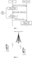
- FIG. 1 a process of adding an SCell for UE is shown in FIG. 1 .
- a PCell After an RRC connection is first established between a base station and the UE, and after the UE enters an RRC connected mode, a PCell performs a measurement configuration on the UE.
- the measurement configuration includes a to-be-measured object and a condition for reporting a measurement report.
- the UE After receiving the measurement configuration, the UE performs a measurement for the SCell. After the measurement is completed, if a measured value satisfies the condition for reporting a measurement report, the UE reports a measurement report to the base station.
- the PCell After receiving the measurement report, the PCell performs SCell addition and activation processes.
- Embodiments of this application provide a measurement method, a device, and a system, to avoid occupying an RRC connected mode in a measurement process, and improve data transmission efficiency of a communications system.
- a measurement method is provided, and is applied to UE.
- the method may include: receiving, by the UE, configuration information sent by a network device, where the configuration information is used by the UE to measure a to-be-measured object; and measuring, by the UE in an RRC idle mode, at least one to-be-measured object based on the configuration information, to obtain a measurement result of the at least one to-be-measured object.
- the UE in the RRC idle mode performs the measurement, to avoid occupying an RRC connected mode in a measurement process, improve data transmission efficiency when the UE is in the RRC connected mode, and further improve data transmission efficiency of a communications system.
- the measuring, by the UE in an RRC idle mode, at least one to-be-measured object based on the configuration information may be specifically implemented as: measuring, by the UE in the RRC idle mode, the at least one to-be-measured object based on the configuration information, where the configuration information is used to instruct the UE in the RRC idle mode to measure the to-be-measured object.
- the network device instructs, by using the configuration information, the UE in the RRC idle mode to perform the measurement. This is easy to implement, a slight change is made to the UE, and compatibility is high.
- the measuring, by the UE in an RRC idle mode, at least one to-be-measured object based on the configuration information may be specifically implemented as: measuring, by the UE in the RRC idle mode, the at least one to-be-measured object based on a notification of the network device or a preconfigured rule, and the configuration information, where the notification of the network device or the preconfigured rule is used to instruct the UE in the RRC idle mode to measure the to-be-measured object.
- the notification of the network device or the preconfigured rule is used to instruct, when the UE receives the configuration information, the UE in the RRC idle mode to perform the measurement.
- a sending moment of the notification of the network device or a configuration moment of the preconfigured rule, or a sending moment of the notification of the network device or content of the preconfigured rule may be determined based on an actual requirement. This is not specifically limited in this solution of this application, so that flexibility of this solution is improved.
- the configuration information may be actively sent by the network device, or may be sent by the network device based on a request of the UE.
- the measurement method provided in this application may further include: sending, by the UE, a measurement request indication to the network device, where the indication is used to instruct the network device to send the configuration information.
- the receiving, by the UE, configuration information sent by a network device may be specifically implemented as: receiving, by the UE, a system broadcast message that is sent by the network device and that includes the configuration information; or receiving, by the UE, an RRC connection release message that is sent by the network device and that includes the configuration information.
- a specific implementation in which the network device sends the configuration information when the UE is in the RRC idle mode or RRC connected mode is provided, so that this solution of this application covers a plurality of application scenarios.
- the measurement method provided in this application may further include: determining, by the UE, whether the UE has a UE feature for performing a measurement; and if the UE has the UE feature for performing a measurement, measuring, by the UE in the RRC idle mode, the at least one to-be-measured object based on the configuration information, to obtain the measurement result of the at least one to-be-measured object.
- the UE determines, based on the feature of the UE, whether to measure the to-be-measured object based on the configuration information when receiving the configuration information.
- the UE feature for performing a measurement may include but is not limited to at least one of the following features: a capability of the UE that is higher than or equal to a preset capability, a type of a service to be initiated by the UE, a preset UE type, and the like.
- the measurement method provided in this application may further include: sending, by the UE, a measurement report to the network device, where the measurement report includes report content of some or all of the at least one to-be-measured object, and report content of one to-be-measured object includes identification (identification, ID) information of the to-be-measured object, or ID information and a measurement result of the to-be-measured object.
- the UE feeds back the report to the network device based on the measurement performed by the UE in the RRC idle mode on the to-be-measured object, to respond to the configuration information sent by the network device.
- the measurement report may include: report content of a to-be-measured object that is in the at least one to-be-measured object and whose measurement result satisfies a preset condition; or the measurement report may include: report content of the at least one to-be-measured object.
- the measurement report may include: after the measuring, by the UE in an RRC idle mode, at least one to-be-measured object based on the configuration information, to obtain a measurement result of the at least one to-be-measured object, the measurement method provided in this application may further include: if the UE enters an RRC connection establishment process or an RRC connected mode, sending, by the UE, the measurement report to the network device; and if the UE is in the RRC idle mode, measuring, by the UE in the RRC idle mode, the at least one to-be-measured object based on the configuration information again, to obtain a measurement result of the at least one to-be-measured object, where a latest measurement result is recorded for a same to-be-measured object.
- content in this implementation may be cyclically performed for a plurality of times until the UE enters the RRC connection establishment process or the RRC connected mode, and then the UE sends the measurement report to the network device, to ensure that content of the measurement report is in a latest network state.
- the sending, by the UE, the measurement report to the network device may be specifically implemented as: sending, by the UE in the RRC connected mode, the measurement report to the network device by using RRC signaling or a media access control (Media Access Control, MAC) control element (control element, CE); or sending, by the UE, the measurement report to the network device by using an Msg3 message or an Msg5 message in the RRC connection establishment process.
- RRC signaling or a media access control (Media Access Control, MAC) control element (control element, CE); or sending, by the UE, the measurement report to the network device by using an Msg3 message or an Msg5 message in the RRC connection establishment process.
- MAC Media Access Control
- CE media access control element
- the measurement method provided in this application may further include: receiving, by the UE, a request message that is sent by the network device and that is used to request the UE to send the measurement report; and the sending, by the UE, the measurement report to the network device may be specifically implemented as: after receiving the request message, sending, by the UE, the measurement report to the network device.
- the UE sends the measurement report based on the request of the network device, to implement reporting as required and save system resources.
- the request message used to request the UE to send the measurement report may include a random access response (Random access response, RAR) message or an Msg4 message, and a function of the request message may be implemented by using indication information in the message.
- RAR Random access response
- Msg4 Msg4 message
- the measurement report includes report content of to-be-measured objects arranged in descending order of measurement results.
- the configuration information may further include at least one of the following information: a preset condition, bandwidth information of the to-be-measured object, information indicating whether the to-be-measured object is a licensed carrier, period information, and a UE feature for performing a measurement.
- a preset condition bandwidth information of the to-be-measured object
- information indicating whether the to-be-measured object is a licensed carrier period information
- a UE feature for performing a measurement In content included in the configuration information, a specific manner of measuring the to-be-measured object by the UE based on the configuration information is configured.
- the preset condition may include: a to-be-measured object measurement criterion, or a preset event, or being greater than or equal to a preset threshold.
- the to-be-measured object includes: a to-be-measured cell, or a to-be-measured carrier, or a to-be-measured beam beam, or a to-be-measured pilot.
- the configuration information may further include ID information of the at least one to-be-measured object.
- the at least one to-be-measured object is specified in the configuration information.
- the at least one to-be-measured object may alternatively be customized by the UE.
- the at least one to-be-measured object may be a to-be-measured object that already serves the UE within a preset time period, or a to-be-measured object that currently serves the UE.
- ID information of a to-be-measured object is used to uniquely identify the to-be-measured object. Any information that can uniquely determine a to-be-measured object may be referred to as the ID information of the to-be-measured object described in this application.
- the ID information of the to-be-measured object may include but is not limited to: a physical layer cell ID of the to-be-measured object, or a conversion ID of a physical layer cell ID of the to-be-measured object, or a global cell ID of the to-be-measured object, or a conversion ID of a global cell ID of the to-be-measured object, or center frequency information of the to-be-measured object, or frequency information of a to-be-measured carrier.
- the configuration information may further include a measurement parameter
- the measuring, by the UE in an RRC idle mode, at least one to-be-measured object based on the configuration information may be specifically implemented as: measuring, by the UE in the RRC idle mode, the measurement parameter for the at least one to-be-measured object based on the configuration information.
- the network device specifies, in the configuration information, the measurement parameter for measuring the to-be-measured object.
- the measurement parameter used when the UE measures the to-be-measured object may alternatively be stipulated in a preset rule or a protocol.
- another measurement method is provided, and is applied to a network device.
- the method may include: sending, by the network device, configuration information, where the configuration information is used by UE to measure a to-be-measured object; and receiving, by the network device, a measurement report sent by the UE, where the measurement report is obtained by the UE in an idle mode by measuring at least one to-be-measured object.
- the UE in the RRC idle mode measures the to-be-measured object, to avoid occupying an RRC connected mode in a measurement process, improve data transmission efficiency when the UE is in the RRC connected mode, and further improve data transmission efficiency of a communications system.
- the configuration information is used to instruct the UE to measure the to-be-measured object in the RRC idle mode.
- the network device instructs, by using the configuration information, the UE in the RRC idle mode to perform the measurement. This is easy to implement, a slight change is made to the UE, and compatibility is high.
- the sending, by the network device, configuration information may be specifically implemented as: sending, by the network device, a system broadcast message including the configuration information; or sending, by the network device, an RRC connection release message including the configuration information.
- a specific implementation in which the network device sends the configuration information to the UE in the RRC idle mode or RRC connected mode is provided, so that this solution of this application covers a plurality of application scenarios.
- the configuration information may be actively sent by the network device, or may be sent by the network device based on a request of the UE.
- the measurement method provided in this application may further include: receiving, by the network device, a measurement request indication sent by the UE, where the indication is used to instruct the network device to send the configuration information.
- the measurement method provided in this application may further include: sending, by the network device to the UE, a request message used to request the UE to send the measurement report.
- the network device instructs, by using the request message, the UE to send the measurement report, to implement reporting as required and save system resources.
- the request message used to request the UE to send the measurement report may include a random access response (Random access response, RAR) message or an Msg4 message, and a function of the request message may be implemented by using indication information in the message.
- RAR Random access response
- Msg4 Msg4 message
- the measurement report includes report content of some or all of the at least one to-be-measured object; and report content of one to-be-measured object includes identification ID information of the to-be-measured object, or identification ID information and a measurement result of the to-be-measured object.
- the measurement method provided in this application may further include: selecting, by the network device based on the measurement report, at least one to-be-measured object and adding the at least one to-be-measured object as a secondary resource of the UE.
- a specific application scenario of the measurement report is implemented.
- the secondary resource is a concept relative to a primary resource.
- the secondary resource may include: a secondary cell, or a secondary carrier, or a secondary beam, or a secondary pilot.
- an embodiment of this application provides UE.
- the UE may implement a function of the UE in the foregoing method example.
- the function may be implemented by using hardware, or may be implemented by hardware by executing corresponding software.
- the hardware or the software includes one or more modules corresponding to the foregoing function.
- a structure of the UE includes a processor and a transceiver.
- the processor is configured to support the UE in performing a corresponding function in the foregoing method.
- the transceiver is configured to support the UE in communicating with another device.
- the UE may further include a memory.
- the memory is configured to: couple to the processor, and store a program instruction and data that are necessary for the UE.
- an embodiment of this application provides a network device.
- the network device may implement a function implemented by the network device in the foregoing method example.
- the function may be implemented by using hardware, or may be implemented by hardware by executing corresponding software.
- the hardware or the software includes one or more modules corresponding to the foregoing function.
- a structure of the network device includes a processor and a transceiver.
- the processor is configured to support the network device in performing a corresponding function in the foregoing method.
- the transceiver is configured to support the network device in communicating with another device.
- the network device may further include a memory.
- the memory is configured to: couple to the processor, and store a program instruction and data that are necessary for the network device.
- an embodiment of this application provides a computer storage medium, configured to store a computer software instruction used by the foregoing UE.
- the computer software instruction includes a program designed to perform the first aspect.
- an embodiment of this application provides a computer storage medium, configured to store a computer software instruction used by the foregoing network device.
- the computer software instruction includes a program designed to perform the second aspect.
- an embodiment of this application provides a communications system, including the UE according to any one of the foregoing aspects or the possible implementations.
- the communications system may further include the network device according to any one of the foregoing aspects or the possible implementations.
- this application provides a measurement method, applied to a network device and UE in a wireless communications system.
- a basic principle of the measurement method is as follows: UE measures a to-be-measured object in an RRC idle mode, to prevent the measurement from occupying an RRC connected mode, thereby improving data transmission efficiency of a communications system.
- the network device described in this application is a network side device that provides a communications service for UE in a wireless communications system.
- network devices may have different names, but all the network devices may be understood as the network device described in this application.
- a type of the network device is also not specifically limited in the embodiments of this application.
- a network device in a universal mobile telecommunications system is referred to as a base station (Base Station, BS)
- a network device in an LTE system is referred to as an evolved NodeB (evolved Node B, eNB)
- a network device in a new radio (NEW Radio, NR) system is referred to as a next generation Node B (next generation Node B, gNB), or the like, which is not enumerated herein.
- All network side devices that provide communications services for UE in a wireless communications system may be understood as the network device described in this application.
- the UE described in this application is a mobile communications device used by a user.
- the UE may be a mobile phone, a tablet computer, a notebook computer, an ultra-mobile personal computer (Ultra-mobile Personal Computer, UMPC), a netbook, a personal digital assistant (Personal Digital Assistant, PDA), an ebook, a mobile television, a wearable device, a personal computer (Personal Computer, PC), or the like.
- terminals may have different names, but all the terminals may be understood as the UE described in this application.
- a type of the UE is not specifically limited in the embodiments of this application.
- the measurement method provided in this application is applied to a wireless communications system architecture shown in FIG. 2 .
- the wireless communications system architecture includes at least one network device 201 and at least one UE 202 that communicates with the network device 201.
- FIG. 2 merely shows an example of a wireless communications network architecture.
- a quantity of network devices 201, a type of the network device 201, a quantity of UEs 202, a type of the UE 202, and the like that are included in the wireless communications system architecture may all be configured based on an actual requirement, and are not specifically limited in FIG. 2 .
- the network device 201 is shown as a base station, and the UE 202 is shown as a mobile phone. This is merely an example for description, and does not constitute a limitation.
- the wireless communications system architecture shown in FIG. 2 may be an LTE network, a universal mobile telecommunications system (Universal Mobile Telecommunications System, UMTS) network, or another network.
- UMTS Universal Mobile Telecommunications System
- Atype of a network to which the solutions of this application are applied is not specifically limited in the embodiments of this application.
- the word such as “example” or “for example” is used to represent giving an example, an illustration, or a description. Any embodiment or design scheme described as an “example” or “for example” in the embodiments of this application should not be explained as being more preferred or having more advantages than another embodiment or design scheme. Exactly, use of the word “example”, “for example”, or the like is intended to present a related concept in a specific manner, to facilitate understanding.
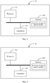
- FIG. 3 shows UE 30 related to the embodiments of this application.
- the UE 30 may be the UE 202 in the wireless communications system architecture shown in FIG. 2 .
- the UE 30 may include a processor 301, a memory 302, and a transceiver 303.
- the memory 302 may be a volatile memory (volatile memory), for example, a random access memory (random-access memory, RAM); or a non-volatile memory (non-volatile memory), for example, a read-only memory (read-only memory, ROM), a flash memory (flash memory), a hard disk (hard disk drive, HDD), or a solid-state drive (solid-state drive, SSD); or a combination of the foregoing types of memories.
- the memory 302 is configured to store program code and a configuration file that can implement the method in this application.
- the processor 301 is a control center of the UE 30, and may be a central processing unit (central processing unit, CPU), may be an application-specific integrated circuit (Application Specific Integrated Circuit, ASIC), or may be configured as one or more integrated circuits, for example, one or more microprocessors (digital signal processor, DSP) or one or more field programmable gate arrays (Field Programmable Gate Array, FPGA), that implement the embodiments of this application.
- the processor 301 may run or execute a software program and/or a module stored in the memory 302, and invoke data stored in the memory 302, to perform various functions of the UE 30.
- the transceiver 303 is used for interaction between the UE 30 and another unit.
- the transceiver 303 may be a transmit and receive antenna of the UE 30.
- the processor 301 runs or executes the software program and/or the module stored in the memory 302, and invokes the data stored in the memory 302, to perform the following functions:
- the transceiver 303 receiving, by using the transceiver 303, configuration information sent by a network device, where the configuration information is used by the UE to measure a to-be-measured object; and measuring at least one to-be-measured object in an RRC idle mode based on the configuration information, to obtain a measurement result of the at least one to-be-measured object.
- FIG. 4 shows a network device 40 related to the embodiments of this application.
- the network device 40 may be the network device 201 in the wireless communications system architecture shown in FIG. 2 .
- the network device 40 may include a processor 401, a memory 402, and a transceiver 403.
- the memory 402 may be a volatile memory, for example, a RAM; or a non-volatile memory, for example, a ROM, a flash memory, an HDD, or an SSD; or a combination of the foregoing types of memories.
- the memory 402 is configured to store program code and a configuration file that can implement the method in this application.
- the processor 401 is a control center of the network device 40, and may be a CPU, may be an ASIC, or may be configured as one or more integrated circuits, for example, one or more DSPs or one or more FPGAs, that implement the embodiments of this application.
- the processor 401 may run or execute a software program and/or a module stored in the memory 402, and invoke data stored in the memory 402, to perform various functions of the network device 40.
- the transceiver 403 is used for interaction between the network device 40 and another unit.
- the transceiver 403 may be a transmit and receive antenna of the network device 40.
- the processor 401 runs or executes the software program and/or the module stored in the memory 402, and invokes the data stored in the memory 402, to perform the following functions: sending, by using the transceiver 403, configuration information, where the configuration information is used by UE to measure a to-be-measured object; and receiving, by using the transceiver 403, a measurement report sent by the UE, where the measurement report is obtained by the UE in an idle mode by measuring at least one to-be-measured object.
- an embodiment of this application provides a measurement method, applied to a process of interaction between UE and a network device in a wireless communications system.
- the measurement method provided in this embodiment of this application is described in detail by describing the process of interaction between the UE and the network device.
- the measurement method may include the following steps.
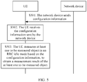
- the network device sends configuration information.
- the configuration information is used by the UE to measure a to-be-measured object.
- the configuration information may be only one piece of indication information used by the UE to measure the to-be-measured object when receiving the configuration information.
- specific details such as the to-be-measured object, measurement content, and a measurement scenario are not limited.
- the configuration information may be used by the UE to measure the to-be-measured object in an RRC idle mode.
- the configuration information may be information that includes a configuration parameter.
- the configuration parameter is used to indicate specific details when the UE measures the to-be-measured object.
- the configuration information may be at least one of the configuration parameters.
- First-type configuration parameter ID information of at least one to-be-measured object.
- the at least one to-be-measured object is a measurement target when the UE performs a measurement.
- the to-be-measured object may include: a to-be-measured cell, or a to-be-measured carrier, or a to-be-measured beam, or a to-be-measured pilot.
- a type of the to-be-measured object is not specifically limited in this embodiment of this application.
- ID information of a to-be-measured object is used to uniquely determine the to-be-measured object.
- ID information of a to-be-measured object is used as a configuration parameter, to indicate a target measurement object when the UE measures a to-be-measured object.
- the ID information of the to-be-measured object may include: a physical layer cell ID of the to-be-measured object, or a conversion ID of a physical layer cell ID of the to-be-measured object, or a global cell ID of the to-be-measured object, or a conversion ID of a global cell ID of the to-be-measured object, or center frequency information of the to-be-measured object, or frequency information of the to-be-measured object.
- Each to-be-measured object has its own dedicated operating frequency band. Therefore, a to-be-measured object can be uniquely determined by using center frequency information of the to-be-measured object.
- the center frequency information may be a frequency value of a center frequency, or may be a channel number of a center frequency, or the like. This is not specifically limited in this embodiment of this application.
- the physical layer cell ID of the to-be-measured object and the global cell ID of the to-be-measured object are unique IDs allocated to the to-be-measured object from physical layer and global perspectives.
- a to-be-measured object can be uniquely determined by using a physical layer cell ID of the to-be-measured object and a global cell ID of the to-be-measured object.
- the conversion ID of the physical layer cell ID of the to-be-measured object and the conversion ID of the global cell ID of the to-be-measured object are IDs obtained after the physical layer cell ID of the to-be-measured object and the global cell ID of the to-be-measured object are converted by using a mapping relationship.
- a to-be-measured object can be uniquely determined by obtaining a physical layer cell ID of the to-be-measured object and a global cell ID of the to-be-measured object by searching for a mapping relationship by using a conversion ID of the physical layer cell ID of the to-be-measured object and a conversion ID of the global cell ID of the to-be-measured object.
- the conversion ID may have different names, for example, a report ID or an index ID. Any ID that corresponds, by using a mapping relationship, to an ID that can uniquely determine a to-be-measured object is the conversion ID referred to in this application.
- Table 1 shows an example of a mapping relationship between a physical layer cell ID of a to-be-measured object and a conversion ID of the physical layer cell ID of the to-be-measured object.
- a conversion ID of a physical layer cell ID of a to-be-measured object is an ID 6
- the physical layer cell ID of the to-be-measured object is an ID 3
- the to-be-measured object can be uniquely determined by using the ID 3.
- Table 1 Physical layer cell ID of a to-be-measured object Conversion ID of the physical layer cell ID of the to-be-measured object ID 1 ID 4 ID 2 ID 5 ID 3 ID 6 ... ...
- Table 1 shows the mapping relationship by merely using an example, and does not specifically limit content and a form of the mapping relationship.
- the foregoing example is merely an example for describing the ID information of the to-be-measured object, and is not a specific limitation thereto. In an actual application, any information that can be used to uniquely determine a to-be-measured object may be used as the ID information of the to-be-measured object described in this application.
- the configuration information when the configuration information includes the first-type configuration parameter, to be specific, includes the ID information of the at least one to-be-measured object, the configuration information indicates an object when the UE performs a measurement.
- Second-type configuration parameter bandwidth information of the to-be-measured object.
- the bandwidth information of the to-be-measured object reflects a quantity of bandwidth resources occupied by the to-be-measured object.
- the configuration information includes the second-type configuration parameter, to be specific, includes the bandwidth information of the to-be-measured object, the configuration information indicates a bandwidth range when the UE performs a measurement.
- Third-type configuration parameter information indicating whether the to-be-measured object is a licensed carrier.
- the information indicating whether the to-be-measured object is a licensed carrier is used to indicate whether the to-be-measured object is a licensed carrier.
- the configuration information includes the third-type configuration parameter, to be specific, includes the information indicating whether the to-be-measured object is a licensed carrier
- the configuration information indicates a feature of the to-be-measured object when the UE performs a measurement, to ensure an accurate measurement, and enable the UE to perform the measurement based on a feature of an unlicensed carrier.
- a time when a secondary component carrier is in a busy mode and a time when the secondary component carrier is in an idle mode are detected in a listen before talk (listen before talk, LBT) manner; or a received signal strength indication (Received Signal Strength Indication, RSSI) measurement manner is performed.
- a listen before talk listen before talk
- RSSI Received Signal Strength Indication
- Fourth-type configuration parameter period information.
- the period information reflects a time interval between two measurements.
- the configuration information includes the fourth-type configuration parameter, to be specific, includes the period information
- the configuration information indicates a period of a measurement performed by the UE.
- the period information may be a preset fixed period, or may be configured based on a discontinuous reception (Discontinuous Reception, DRX) period. This is not specifically limited in this embodiment of this application.
- DRX discontinuous Reception
- Fifth-type configuration parameter a UE feature for performing a measurement.
- Content of the UE feature for performing a measurement is some features of the UE.
- the feature may be a performance feature, or may be a service feature, or may be a UE type feature.
- the configuration information instructs the UE that has the UE feature for performing a measurement to measure the to-be-measured object when receiving the configuration information.
- the UE feature for performing a measurement may be that a service to be initiated by the UE is traffic intensive, or may be that a terminal type of the UE is a video mobile phone.
- the UE feature for performing a measurement may be one or more aspects. This is not specifically limited in this embodiment of this application.
- Sixth-type configuration parameter a measurement parameter.
- the measurement parameter is used to indicate a measured value during a measurement.
- the configuration information includes the measurement parameter, and the configuration information instructs the UE to measure the to-be-measured object, the measured value is a measurement parameter in the measurement configuration parameters.
- the measurement parameter may include but is not limited to: a reference signal received power (Reference Signal Receiving Power, RSRP), or reference signal received quality (Reference Signal Receiving Quality, RSRQ), or a received signal strength indication (Received Signal Strength Indication, RSSI), or a signal to interference plus noise ratio (Signal to Interference plus Noise Ratio, SINR), or the like.
- RSRP Reference Signal Receiving Power
- RSRQ reference signal received quality
- RSSI received Signal Strength Indication
- SINR Signal to Interference plus Noise Ratio
- a type of the measurement parameter may alternatively be configured based on an actual requirement. The foregoing example does not specifically limit the type of the measurement parameter.
- Seventh-type configuration parameter a maximum quantity of UEs that need to perform a measurement.
- the configuration information When the configuration information includes the maximum quantity of UEs that need to perform a measurement, the configuration information indicates a quantity of to-be-measured objects when the UEs perform the measurements.
- the configuration information not only includes ID information of at least one to-be-measured cell that indicates to-be-measured objects, but also includes a maximum quantity N of UEs that need perform a measurement.
- N is less than a quantity of the to-be-measured objects indicated by the ID information of the at least one to-be-measured cell
- the UEs select, from the to-be-measured objects indicated by the ID information of the at least one to-be-measured cell, N to-be-measured objects for the measurements.
- a specific selection manner is not specifically limited in this embodiment of this application.
- Seventh-type configuration parameter a preset condition.
- the preset condition is a preconfigured condition, and if the condition is satisfied, a specific operation can be performed after a measurement is performed.
- the "specific operation" herein may include but is not limited to:
- the to-be-measured object is used as a secondary resource, or a measurement result of the to-be-measured object is sent to the network device, or a measurement result of the to-be-measured object is included in a measurement report.
- content of the specific operation may be configured based on an actual requirement. This is not specifically limited in this embodiment of this application.
- the preset condition may include: a to-be-measured object measurement criterion, or a preset event, or being greater than or equal to a preset threshold.
- Content of the preset condition may be configured based on an actual requirement. This is not specifically limited in this embodiment of this application.
- a definition may be as follows: When the measurement result of the to-be-measured object is greater than or equal to the preset threshold, the to-be-measured object is added to the measurement report.
- the preset event may include an existing defined event A4, or content of the preset event may be configured based on an actual requirement. This is not specifically limited in this embodiment of this application. Content of an event such as a defined event A4 is not described in detail in this embodiment of this application.
- the preset condition may alternatively be configured to be less than or equal to a first preset threshold.
- Values of the preset threshold and the first preset threshold may be configured based on an actual requirement. This is not specifically limited in this embodiment of this application.
- Table 2 Srxlev_Scell Received value (dB) selected for a neighboring to-be-measured object Squal_Scell Quality value (dB) selected for a neighboring to-be-measured object Q offsettemp Offset (dB) between the to-be-measured object and a service object of the UE Q rxlevmeas Received power (RSRP) of the to-be-measured object Q qualmeas Signal quality (RSRQ) of the to-be-measured object Q rxlevmin Minimum required reception range (dBm) for measuring the to-be-measured object Q qualmin Minimum quality range (dB) for measuring the to-be-measured object Q rxlevminoffset Offset of a public land mobile network (public land Mobile Network, PLMN) received value Q qualminoffset Offset of PLMN received quality Pcompensation If the UE supports coverage enhancement (coverage enhancement, CE) or bandwidth reduced low complexity (
- the service object of the UE is an object of a same type as the to-be-measured object.
- the service object of the UE refers to a serving cell of the UE; or when the to-be-measured object is a to-be-measured carrier, the service object of the UE refers to a service carrier of the UE.
- the content of the to-be-measured object measurement criterion is merely a possible implementation, and is not a specific limitation on the to-be-measured object measurement criterion.
- the to-be-measured object measurement criterion may be deformation or conversion of the content of the foregoing example, and some or all of the parameters listed in Table 2 are included. Therefore, all to-be-measured object measurement criteria constructed by using a measurement criterion idea shall fall within the protection scope of the solutions of this application.
- the to-be-measured object measurement criterion may alternatively be an S criterion.
- Content of the S criterion is not described in detail in this embodiment of this application.
- the configuration information may include at least one of the foregoing seven types of configuration parameters, or the measurement configuration parameter may further include another configuration parameter. Details are not described one by one in this embodiment of this application.
- the network device in S501 may send the configuration information through broadcast, to be specific, there is no destination UE; or the network device may send the configuration information to the UE.
- FIG. 5 merely shows a manner of sending the configuration information to the UE in S501, and does not specifically limit the manner.
- the network device may actively send the configuration information, or may send the configuration information based on a request of the UE.
- a prerequisite for performing S501 is not specifically limited in this embodiment of this application.
- the measurement method provided in this embodiment of this application may further include S501a and S501b.
- the UE sends, to the network device, a request indication indicating that the UE expects to perform a measurement when the UE is in the idle mode.
- the network device receives the request indication indicating that the UE expects to perform a measurement when the UE is in the idle mode.
- the UE when the UE is capable of performing a measurement when the UE is in the RRC idle mode, to reduce a latency when the UE is in the RRC connected mode, the UE selects to perform a measurement when the UE is in the RRC idle mode. In this case, the UE sends the request indication to a serving object on which the UE camps, and a network device of the service object performs S501.
- a specific implementation in which the network device sends the configuration information may include but is not limited to the following two implementations:
- Implementation 1 The network device sends a system broadcast message including the configuration information.
- the network device sends the configuration information through broadcast, and the UE in the RRC idle mode receives the configuration information.
- Implementation 2 The network device sends an RRC connection release message including the configuration information.
- the network device sends the configuration information by using the RRC connection release message, and the UE in the RRC connected mode receives the configuration information.
- the UE receives the configuration information sent by the network device.
- the configuration information received by the UE in S502 is the configuration information sent by the network device in S501, and is already described in detail in S501, and details are not described herein again.
- the receiving, by the UE may also include the following two implementations.
- Implementation A The UE receives the system broadcast message that is sent by the network device and that includes the configuration information.
- Implementation B The UE receives the RRC connection release message that is sent by the network device and that includes the configuration information.
- the UE in the RRC idle mode measures at least one to-be-measured object based on the configuration information, to obtain a measurement result of the at least one to-be-measured object.
- the at least one to-be-measured object measured by the UE may be indicated by using ID information of the at least one to-be-measured object that is included in the configuration information, or may be determined by the UE.
- the UE may determine that the at least one to-be-measured object is a to-be-measured object that serves the UE in a preset time period.
- the UE may determine that the at least one to-be-measured object is a to-be-measured object that currently serves the UE.
- a manner of determining the at least one to-be-measured object is not specifically limited in this embodiment of this application.
- a process of determining the at least one to-be-measured object and content of the determined at least one to-be-measured object are not specifically limited in this embodiment of this application either.
- the to-be-measured object when the to-be-measured object is a to-be-measured cell, the to-be-measured cell may be a neighboring cell co-site with a serving cell of the UE, or the to-be-measured cell may be a cell that serves the UE within preset duration.
- the UE measures the to-be-measured object based on a configuration parameter.
- the configuration parameter may be included in the configuration information received in S502, or may be predefined and stored in the UE. This is not specifically limited in this embodiment of this application. Specific content of the configuration parameter is already described in detail in S501, and details are not described herein again.
- S503 may be specifically implemented as:
- the UE in the RRC idle mode measures the measurement parameter for the at least one to-be-measured object based on the configuration information.
- the measurement result of the to-be-measured object is a measurement value of the measurement parameter.
- the measurement parameter may be included in the configuration information received in S502, or may be predefined and stored in the UE.
- the measurement parameter may be an RSRP, RSRQ, an RSSI, or an SINR
- the measurement result is a value of an RSRP, RSRQ, an RSSI, or an SINR that is specifically measured.
- implementations of S503 are also different. Specifically, the following two cases may be included:
- Case 1 The configuration information is used to instruct the UE in the RRC idle mode to measure the to-be-measured object.
- S503 is specifically implemented as: The UE in the RRC idle mode measures the at least one to-be-measured object based on the configuration information.
- Case 2 The UE in the RRC idle mode is instructed, by using a notification of the network device or a preconfigured rule instead of using the configuration information, to measure the to-be-measured object.
- the UE in the RRC idle mode measures the at least one to-be-measured object based on the notification of the network device or the preconfigured rule, and the configuration information.
- the notification of the network device or the preconfigured rule is used to instruct the UE in the RRC idle mode to measure the to-be-measured object.
- the notification of the network device may be a notification specially used to instruct the UE in the RRC idle mode to measure the to-be-measured object.
- a sending moment and content of the notification are not specifically limited in this embodiment of this application.
- the preconfigured rule may be a protocol executed by the UE, and the protocol stipulates that the UE in the RRC idle mode measures the to-be-measured object when receiving the configuration information.
- the preconfigured rule may alternatively be a configuration rule in another form, for example, a rule that is defined by a manufacturer of the UE and that is executed by the UE. Content and a form of the preconfigured rule are not specifically limited in this embodiment of this application.
- S503 of measuring, by the UE in the RRC idle mode, the at least one to-be-measured object may be directly performed after S502 without considering factors such as quality of service of the service object of the UE.
- Condition 1 may be a UE feature for performing a measurement.
- the UE feature for performing a measurement may be a performance feature of the UE, or may be information about a bearer that needs to be established by the UE. This is not specifically limited in this application.
- Condition 1 may be that the UE has the UE feature for performing a measurement, for example, whether the UE supports carrier aggregation. If the UE cannot support carrier aggregation, the UE does not perform the measurement in S503.
- Condition 1 may be that the information about the bearer that needs to be established by the UE indicates that a service to be initiated by the UE is traffic intensive.
- the bearer that needs to be established by the UE is a video service, to be specific, the bearer required by the UE needs a relatively large throughput to ensure a service requirement, and the UE performs the measurement in S503.
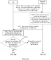
- the at least one to-be-measured object may be performed based on Condition 1 after S502, as shown in FIG. 6A and FIG. 6B , before S503, the measurement method provided in this embodiment of this application may further include S503a.
- the UE determines whether the UE has the UE feature for performing a measurement.
- the UE feature for performing a measurement may be a preset rule, or may be included in the configuration information. This is not specifically limited in this embodiment of this application. Content of the UE feature for performing a measurement is already described in detail in S501, and details are not described herein again.
- S503 is performed. If it is determined in S503a that the UE has the UE feature for performing a measurement, the received configuration information is discarded.
- the UE feature for performing a measurement is that the UE is a video mobile phone.
- the mobile phone receives the configuration information in S502
- the mobile phone performs S503a and determines that the mobile phone is not a video mobile phone, and does not measure the to-be-measured object.
- a process of measuring the to-be-measured object by the UE in S503 is the same as an existing measurement process, so that the process of measuring the to-be-measured object by the UE in S503 is not described in detail in this embodiment of this application. Any measurement performed on the to-be-measured object by the UE in the RRC idle mode shall fall within the protection scope of the solutions of this application.
- the UE in the RRC idle mode performs the measurement, to avoid occupying the RRC connected mode in the measurement process, improve data transmission efficiency when the UE is in the RRC connected mode, and further improve data transmission efficiency of a communications system.
- the measurement in step S503 there may be a plurality of applications for the measurement result.
- the measurement report may be sent, or quality of service is determined.
- the measurement result may be directly applied after S503 is performed.
- an execution condition may alternatively be set for an application of the measurement result. After S503, when the execution condition is satisfied, the measurement result is applied again.
- the execution condition may be a state of the UE, a state of the network device, a state of a network, or the like. Specific content of the execution condition is not limited in this embodiment of this application.
- an execution condition of the application may be set to that the UE enters an RRC connection establishment process or enters the RRC connected mode.
- different execution conditions may be preset for applications of different measurement results, and details are not described herein.
- an execution condition is set for an application of the measurement result, after S503, it is first determined whether the execution condition is satisfied, and if the execution condition is satisfied, the measurement result is applied. If the execution condition is not satisfied, the process of measuring, by the UE in the RRC idle mode, the at least one to-be-measured object based on the configuration information, to obtain a measurement result of the at least one to-be-measured object in S503 is performed again. In a process of performing S503 for a plurality of times, for a same to-be-measured object, a latest measurement result is recorded, to ensure timeliness of the measurement result.
- a feasible application of the measurement result is that the UE sends a measurement report to the network device, to feed back a response to the configuration information sent by the network device in S501. Therefore, as shown in FIG. 6A and FIG. 6B , after S503, the measurement method provided in this embodiment of this application may further include S504 and S505.
- the UE sends a measurement report to the network device.
- the measurement report includes report content of some or all of the at least one to-be-measured object.
- Report content of a to-be-measured object may include ID information of the to-be-measured object, or ID information and a measurement result of the to-be-measured object.
- the UE needs to obtain the measurement report, and then sends the measurement report to the network device. If the measurement in S503 is the first measurement, the measurement report is generated based on content of the measurement report and a measurement report of the at least one to-be-measured object that is obtained through the measurement in S503. If the measurement in S503 is not the first measurement, an existing measurement report is updated based on content of the measurement report and a latest measurement report of the at least one to-be-measured object that is obtained through the measurement in S503.
- the updating an existing measurement report may include: adding content to the measurement report, or deleting partial content from the measurement report, or replacing partial content in the measurement report.
- Content of a stored and updated measurement report is obtained based on a measurement result of a latest measurement.
- the content in the measurement report may be configured based on an actual requirement, and may specifically include but is not limited to the following two implementations.
- the measurement report includes report content of a to-be-measured object that is in the at least one to-be-measured object and whose measurement result satisfies a preset condition.
- the measurement report may include ID information of a to-be-measured object that is in the at least one to-be-measured object and whose measurement result satisfies the preset condition.
- the UE needs to first generate the measurement report, and then sends the measurement report to the network device.
- the measurement report includes the report content of the to-be-measured object whose measurement result satisfies the preset condition, after S503, the UE first compares each measurement result of the at least one measured to-be-measured object with the preset condition, and then generates the measurement report or updates the measurement report.
- the generating the measurement report is storing the report content of the to-be-measured object whose measurement result satisfies the preset condition as the measurement report.
- the updating the measurement report ensures that the measurement report includes report content of a to-be-measured object whose measurement result satisfies the preset condition after a latest measurement.
- Specific implementations may include the following three cases:
- the measurement report includes report content of the at least one to-be-measured object measured by the UE.
- the UE needs to first generate the measurement report, and then sends the measurement report to the network device.
- the measurement report includes the report content of the at least one to-be-measured object measured by the UE in S503, after S503, the UE needs to generate the measurement report or update the measurement report.
- the generating the measurement report is storing the report content of the at least one to-be-measured object measured by the UE in S503 as the measurement report.
- the updating the measurement report ensures that the measurement report includes the report content of the at least one to-be-measured object measured by the UE in S503 after a latest measurement.
- Specific implementations may include the following two cases:
- the measurement report may include report content of to-be-measured objects arranged in descending order of measurement results, to be specific, the report content is sorted and stored in the measurement report.
- a state of the UE may not be limited, and may be configured based on an actual requirement.
- the UE may send the measurement report after entering the RRC connected mode, or in an RRC connection establishment process.
- the UE may alternatively perform S504 in another state in which communication with the network device is supported.
- a dedicated message may be configured for sending the measurement report, or an existing communication message between the UE and the network device may be used to carry the measurement report for sending.
- a form of sending the measurement report is not specifically limited in this embodiment of this application.
- a message for sending the measurement report and a location of the measurement report in the message may be pre-specified and known by both the UE and the network device.
- the UE in the RRC connected mode may send the measurement report to the network device by using RRC signaling or an MAC CE.
- the UE sends the measurement report to the network device by using an Msg3 message or an Msg5 message.
- the measurement method provided in this embodiment of this application may further include S504a.
- the UE queries an RRC mode of the UE.
- the RRC mode may include the RRC idle mode, the RRC connection establishment process, and the RRC connected mode.
- S504a a process of querying the RRC mode of the UE in S504a is not described in detail in this embodiment of this application.
- the UE may perform S504a by querying information such as a status indication bit of the UE or a specific flag bit.
- S504a may be performed in another manner. This is not specifically limited in this application.
- the UE selects to re-perform S503 or S504. If it is queried in S504a that the UE enters the RRC connection establishment process or the RRC connected mode, S504 is performed. If it is queried in S504a that the UE is in the RRC idle mode, S503 is re-performed. When S503 is performed for a plurality of times, a latest measurement result is recorded for a same to-be-measured object, and the measurement report is obtained based on the latest measurement result.
- the network device receives the measurement report sent by the UE.
- the measurement report is obtained by the UE in the RRC idle mode by measuring the at least one to-be-measured object.
- the measurement report received in S505 is the measurement report sent in S504. The content of the measurement report is already described in detail in S504, and details are not described herein again.
- a dedicated message may be configured for sending the measurement report, or an existing communication message between the UE and the network device may be used to carry the measurement report for sending.
- a form of sending the measurement report is not specifically limited in this embodiment of this application.
- a message for sending the measurement report and a location of the measurement report in the message may be pre-specified and known by both the UE and the network device. Therefore, in S505, the network device accurately receives, based on the preconfigured message for sending the measurement report by the UE and the location of the measurement report in the message, the measurement report sent by the UE.
- the network device may receive, in RRC signaling or an MAC CE, the measurement report sent by the UE in the RRC connected mode.
- the network device may receive, in an Msg3 or Msg5 message, the measurement report sent by the UE in the RRC connection establishment process.
- the UE may actively send the measurement report to the network device, or may send the measurement report to the network device based on a request of the network device.
- the measurement method provided in this embodiment of this application may further include S504b and S504c.
- the network device sends, to the UE, a request message used to request the UE to send the measurement report.
- the RRC mode of the UE when the network device sends the request message in S504b may be configured based on an actual requirement. This is not specifically limited in this embodiment of this application.
- the request message sent by the network device in S504b may be separately sent, or may be sent in combination with an existing message. This is also not specifically limited in this embodiment of this application.
- the network device sends the configuration information in S501 and the request message in S504b together, to be specific, combines S501 and S504b into one step for execution.
- the network device adds the request message in S504b to an uplink (Uplink, UL) information request message for sending.
- uplink Uplink, UL
- the UE receives the request message that is sent by the network device and that is used to request the UE to send the measurement report.
- S504 is specifically implemented as: After receiving the request message, the UE sends the measurement report to the network device.
- S504a and S504b may be performed at the same time, or may be performed in sequence. This is not specifically limited in this embodiment of this application.
- FIG. 6A and FIG. 6B merely show an execution sequence of S504a and S504b, and does not constitute a specific limitation.
- the network device may perform a related configuration on the UE based on the measurement report, for example, adding a secondary resource.
- the measurement method provided in this embodiment of this application may further include S506.
- the network device selects, based on the measurement report, at least one to-be-measured object and adds the at least one to-be-measured object as a secondary resource of the UE.
- the network device selects, based on the measurement report, the to-be-measured object and adds the to-be-measured object as the secondary resource of the UE.
- An adding rule may be preset, and the to-be-measured object is added based on the adding rule. A specific adding process is not described in detail in this embodiment of this application.
- the adding rule may be that the first several to-be-measured objects in descending order of measurement results are selected and added as secondary resources of the UE.
- the adding rule may be configured based on an actual requirement, and the example herein does not constitute a specific limitation.
- the secondary resource is a concept relative to a primary resource.
- the secondary resource may include: a secondary cell, or a secondary carrier, or a secondary beam, or a secondary pilot.
- the UE and the network device include a corresponding hardware structure and/or software module for implementing each function.
- the UE and the network device include a corresponding hardware structure and/or software module for implementing each function.
- Persons skilled in the art should easily be aware that, in combination with the examples of units and algorithms steps described in the embodiments disclosed in this specification, this application may be implemented by using hardware or a combination of hardware and computer software in this application. Whether a function is performed by using hardware or hardware driven by computer software depends on particular applications and design constraints of the technical solutions. Persons skilled in the art may use different methods to implement the described functions for each particular application, but it should not be considered that the implementation goes beyond the scope of this application.
- the UE and the network device may be divided into functional modules based on the foregoing method examples.
- each functional module may be obtained through division for each corresponding function, or two or more functions may be integrated into one processing module.
- the integrated module may be implemented in a form of hardware, or may be implemented in a form of a software functional module.
- module division is an example, and is merely a logical function division. In an actual implementation, another division manner may be used.
- FIG. 7 is a possible schematic structural diagram of the UE in the foregoing embodiments.
- UE 70 may include a receiving unit 701 and a measurement unit 702.
- the receiving unit 701 is configured to support the UE 70 in performing processes S502 and S504c in FIG. 5 or FIG. 6A and FIG. 6B .
- the measurement unit 702 is configured to support the UE 70 in performing the process S503 in FIG. 5 or FIG. 6A and FIG. 6B . All related content of the steps in the foregoing method embodiment may be cited for describing functions of corresponding functional modules, and details are not described herein again.
- the UE 70 may further include a determining unit 703.
- the determining unit 703 is configured to support the UE 70 in performing the process S503a in FIG. 6A and FIG. 6B .
- the UE 70 may further include a sending unit 704.
- the sending unit 704 is configured to support the UE 70 in performing the process S504 in FIG. 6A and FIG. 6B .
- FIG. 9 is a possible schematic structural diagram of the UE in the foregoing embodiments.
- UE 90 may include a processing module 901 and a communications module 902.
- the processing module 901 is configured to control and manage an action of the UE 90.
- the processing module 901 is configured to support the UE 90 in performing the processes S503, S503a, and S504a in FIG. 5 or FIG. 6A and FIG. 6B ;
- the communications module 902 is configured to support the air conditioner control apparatus 120 in communicating with another network entity; and the processing module 901 is configured to support the UE 90 in performing processes S502, S504c, and S504 in FIG. 5 or FIG. 6A and FIG. 6B by using the communications module 902.
- the UE 90 may further include a storage module 903, configured to store program code and data of the UE 90.
- the processing module 901 may be the processor 301 in the physical structure of the UE 30 shown in FIG. 3 .
- the processing module 901 may be a processor or a controller, for example, may be a CPU, a general-purpose processor, a DSP, an ASIC, an FPGA or another programmable logic device, a transistor logic device, a hardware component, or any combination thereof.
- the processing module 901 may implement or execute various example logical blocks, modules, and circuits described with reference to content disclosed in this application.
- the processor 901 may be a combination of processors implementing a computing function, for example, a combination of one or more microprocessors, or a combination of a DSP and a microprocessor.
- the communications module 902 may be the transceiver 304 in the physical structure of the UE 30 shown in FIG. 3 .
- the communications module 902 may be a communications port, or may be a transceiver, a transceiver circuit, a communications interface, or the like.
- the storage module 903 may be the memory 302 in the physical structure of the UE 30 shown in FIG. 3 .
- the processing module 901 is a processor
- the communications module 902 is a transceiver
- the storage module 903 is a memory
- the UE 90 in FIG. 9 in this embodiment of this application may be the UE 30 shown in FIG. 3 .
- the UE 70 or the UE 90 provided in this embodiment of this application may be configured to implement the method implemented in the foregoing embodiments of this application.
- the UE 70 or the UE 90 provided in this embodiment of this application may be configured to implement the method implemented in the foregoing embodiments of this application.
- only parts related to this embodiment of this application are shown.
- specific technical details refer to the embodiments of this application.
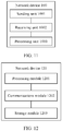
- FIG. 10 is a possible schematic structural diagram of the network device in the foregoing embodiments.
- the network device 100 may include a sending unit 1001 and a receiving unit 1002.
- the sending unit 1001 is configured to support the network device 100 in performing the processes S501 and S504b in FIG. 5 or FIG. 6A and FIG. 6B .
- the receiving unit 1002 is configured to support the network device 100 in performing the processes S501b and S505 in FIG. 5 or FIG. 6A and FIG. 6B . All related content of the steps in the foregoing method embodiments may be cited for describing functions of corresponding functional modules, and details are not described herein again.
- the network device 100 may further include a processing unit 1003.
- the processing unit 1003 is configured to support the network device 100 in performing the process S506 in FIG. 6A and FIG. 6B .
- FIG. 12 is a possible schematic structural diagram of the network device in the foregoing embodiments.
- a network device 120 may include a processing module 1201 and a communications module 1202.
- the processing module 1201 is configured to perform control management on an action of the network device 120.
- the communications module 902 is configured to support the air conditioner control apparatus 120 in communicating with another network entity.
- the processing module 1201 is configured to support, by using the communications module 1202, the network device 120 in performing the processes S501b, S501, S504b, and S505 in FIG. 5 or FIG. 6A and FIG. 6B .
- the processing module 1201 is configured to support the network device 120 in performing the process S506 in FIG. 6A and FIG. 6B .
- the network device 120 may further include a storage module 1203, configured to store program code and data of the network device 120.
- the processing module 1201 may be the processor 401 in the physical structure of the network device 40 shown in FIG. 4 .
- the processing module 1201 may be a processor or a controller, for example, may be a CPU, a general-purpose processor, a DSP, an ASIC, an FPGA or another programmable logic device, a transistor logic device, a hardware component, or any combination thereof.
- the processing module 1201 may implement or execute various example logical blocks, modules, and circuits described with reference to content disclosed in this application.
- the processor 1201 may be a combination of processors implementing a computing function, for example, a combination of one or more microprocessors, or a combination of a DSP and a microprocessor.
- the communications module 1202 may be the transceiver 404 in the physical structure of the network device 40 shown in FIG. 4 .
- the communications module 1202 may be a communications port, or may be a transceiver, a transceiver circuit, a communications interface, or the like.
- the storage module 1203 may be the memory 402 in the physical structure of the network device 40 shown in FIG. 4 .
- the network device 120 in FIG. 12 in the embodiment of this application may be the network device 40 shown in FIG. 4 .
- the network device 100 or the network device 120 provided in the embodiments of this application may be configured to implement the method implemented according to the foregoing embodiments of this application.
- the network device 100 or the network device 120 provided in the embodiments of this application may be configured to implement the method implemented according to the foregoing embodiments of this application.
- only parts related to this embodiment of this application are shown.
- an embodiment of this application provides a measurement system, including the UE according to any one of the foregoing embodiments.
- an embodiment of this application provides a measurement system, including the UE according to any one of the foregoing embodiments and the network device according to any one of the foregoing embodiments.
- the software instruction may include a corresponding software module.
- the software module may be stored in a RAM, a flash memory, a ROM, an erasable programmable read-only memory (Erasable Programmable ROM, EPROM), an electrically erasable programmable read-only memory (Electrically EPROM, EEPROM), a register, a hard disk, a mobile hard disk, a compact disc read-only memory (CD-ROM), or any other form of storage medium well-known in the art.
- a storage medium is coupled to a processor, so that the processor can read information from the storage medium or write information into the storage medium.
- the storage medium may be a component of the processor.
- the processor and the storage medium may be located in an ASIC.
- the ASIC may be located in a core network interface device.
- the processor and the storage medium may exist in the core network interface device as discrete components.
- the computer-readable medium includes a computer storage medium and a communications medium, where the communications medium includes any medium that enables a computer program to be transmitted from one place to another.
- the storage medium may be any available medium accessible to a general-purpose or dedicated computer.
- the disclosed system, apparatus, and method may be implemented in other manners.
- the described apparatus embodiments are merely examples.
- the unit division is merely logical function division and may be other division in actual implementations.
- a plurality of units or components may be combined or integrated into another system, or some features may be ignored or not performed.
- the displayed or discussed mutual couplings or direct couplings or communication connections may be implemented by using some interfaces.
- the indirect couplings or communication connections between the apparatuses or units may be implemented in electronic or other forms.
- the units described as separate parts may or may not be physically separate, and parts displayed as units may or may not be physical units, may be located in one position, or may be distributed on a plurality of network units. Some or all of the units may be selected based on actual requirements to achieve the objectives of the solutions of the embodiments.
- functional units in the embodiments of this application may be integrated into one processing unit, or each of the units may exist alone physically, or two or more units may be integrated into one unit.
- the integrated unit may be implemented in a form of hardware, or may be implemented in a form of hardware in addition to a software functional unit.
- the integrated unit may be stored in a computer-readable storage medium.
- the software functional unit is stored in a storage medium and includes several instructions for instructing a computer device (which may be a personal computer, a server, a network device, or the like) to perform some of the steps of the methods described in the embodiments of this application.
- the foregoing storage medium includes: any medium that can store program code, such as a USB flash drive, a removable hard disk, a read-only memory (Read-Only Memory, ROM), a random access memory (Random Access Memory, RAM), a magnetic disk, or an optical disc.
Landscapes
- Engineering & Computer Science (AREA)
- Computer Networks & Wireless Communication (AREA)
- Signal Processing (AREA)
- Quality & Reliability (AREA)
- Mobile Radio Communication Systems (AREA)
Applications Claiming Priority (1)
| Application Number | Priority Date | Filing Date | Title |
|---|---|---|---|
| PCT/CN2017/097278 WO2019028921A1 (zh) | 2017-08-11 | 2017-08-11 | 一种测量方法、设备及系统 |
Publications (3)
| Publication Number | Publication Date |
|---|---|
| EP3664501A1 true EP3664501A1 (de) | 2020-06-10 |
| EP3664501A4 EP3664501A4 (de) | 2020-07-15 |
| EP3664501B1 EP3664501B1 (de) | 2025-01-01 |
Family
ID=65272782
Family Applications (1)
| Application Number | Title | Priority Date | Filing Date |
|---|---|---|---|
| EP17920734.5A Active EP3664501B1 (de) | 2017-08-11 | 2017-08-11 | Messverfahren, vorrichtung und system |
Country Status (4)
| Country | Link |
|---|---|
| US (1) | US11792669B2 (de) |
| EP (1) | EP3664501B1 (de) |
| CN (2) | CN114125893A (de) |
| WO (1) | WO2019028921A1 (de) |
Cited By (1)
| Publication number | Priority date | Publication date | Assignee | Title |
|---|---|---|---|---|
| EP4521812A4 (de) * | 2022-05-13 | 2025-07-23 | Huawei Tech Co Ltd | Wahrnehmungsverfahren, kommunikationsvorrichtung und computerlesbares speichermedium |
Families Citing this family (10)
| Publication number | Priority date | Publication date | Assignee | Title |
|---|---|---|---|---|
| CN109803280B (zh) * | 2017-11-16 | 2021-04-13 | 维沃移动通信有限公司 | 非连接态用户侧设备的测量方法、装置及用户侧设备 |
| EP3777337A1 (de) * | 2018-04-04 | 2021-02-17 | Telefonaktiebolaget Lm Ericsson (Publ) | Durchführung von zellmessungen |
| CN110636641B (zh) * | 2018-06-25 | 2021-10-15 | 维沃移动通信有限公司 | 一种ca配置信息的处理方法和终端 |
| EP3834571A1 (de) * | 2018-08-10 | 2021-06-16 | Sony Corporation | Frühe messmeldung |
| WO2020190197A1 (en) * | 2019-03-20 | 2020-09-24 | Telefonaktiebolaget Lm Ericsson (Publ) | Flexible early measurement reporting |
| CN111954245B (zh) * | 2019-05-15 | 2022-08-09 | 华为技术有限公司 | 一种通信方法和通信装置 |
| CN116250195A (zh) * | 2020-09-29 | 2023-06-09 | 华为技术有限公司 | 干扰上报的方法与装置 |
| CN112422366A (zh) * | 2020-11-09 | 2021-02-26 | 淄博萃智工业设计咨询有限公司 | 一种前传网络时延特性测量方法及系统 |
| KR20250016344A (ko) * | 2022-08-09 | 2025-02-03 | 노키아 테크놀로지스 오와이 | 라디오 리소스 제어 연결 상태에 대한 개시 |
| WO2024178624A1 (zh) * | 2023-02-28 | 2024-09-06 | 北京小米移动软件有限公司 | 传输测量配置信息的方法、装置以及可读存储介质 |
Family Cites Families (28)
| Publication number | Priority date | Publication date | Assignee | Title |
|---|---|---|---|---|
| CN101374278B (zh) * | 2004-01-08 | 2012-02-29 | 北京三星通信技术研究有限公司 | 通知mbms相关信息的方法 |
| MX2011009554A (es) * | 2009-03-16 | 2011-09-28 | Panasonic Corp | Sistema de comunicacion inalambrica, aparato terminal, aparato de estacion base y metodo de comunicacion inalambrica. |
| US10447441B2 (en) * | 2009-10-29 | 2019-10-15 | Nec Corporation | Wireless communication system, wireless communication method, radio station and program |
| KR101722204B1 (ko) * | 2010-04-27 | 2017-04-03 | 삼성전자주식회사 | 이동통신 시스템에서 핸드오버 지원 정보 제공을 위한 장치 및 방법 |
| CN102111805B (zh) * | 2010-06-18 | 2016-12-28 | 电信科学技术研究院 | 多载波系统的测量配置和上报方法及设备 |
| KR20120118508A (ko) * | 2010-06-18 | 2012-10-26 | 차이나 아카데미 오브 텔레커뮤니케이션즈 테크놀로지 | 멀티캐리어 시스템의 측정배치와 보고방법 및 장치 |
| CN102378240B (zh) * | 2010-08-11 | 2014-01-29 | 电信科学技术研究院 | 一种mdt信息的处理方法和设备 |
| CN102752787B (zh) * | 2011-04-19 | 2016-09-28 | 中兴通讯股份有限公司 | 连接状态最小化路测方法和系统 |
| US9307456B2 (en) * | 2011-07-14 | 2016-04-05 | Lg Electronics Inc. | Method of reporting system information in a wireless communication system and device for supporting same |
| CN102355692A (zh) * | 2011-07-22 | 2012-02-15 | 电信科学技术研究院 | 配置业务质量测量及业务质量测量上报方法和设备 |
| CN102932772A (zh) * | 2011-08-11 | 2013-02-13 | 中兴通讯股份有限公司 | 一种检查记录最小化路测配置的终端及方法 |
| CN103249078A (zh) * | 2012-02-10 | 2013-08-14 | 中兴通讯股份有限公司 | 一种用于最小化路测的吞吐量测量方法和测量节点 |
| CN103260175A (zh) * | 2012-02-16 | 2013-08-21 | 中兴通讯股份有限公司 | 一种基于最小化路测的qos测量方法和系统 |
| CN103634838B (zh) * | 2012-08-24 | 2017-03-29 | 电信科学技术研究院 | 最小化路测测量结果上报方法和设备 |
| KR101817969B1 (ko) * | 2012-10-05 | 2018-01-12 | 닛본 덴끼 가부시끼가이샤 | 무선 통신 시스템, 무선국, 무선 단말, 통신 제어 방법, 및 컴퓨터 판독 가능한 매체 |
| KR102143200B1 (ko) * | 2013-01-09 | 2020-08-28 | 엘지전자 주식회사 | 무선 통신 시스템에서 측정을 수행하기 위한 방법 및 장치 |
| PL3217719T3 (pl) * | 2013-01-18 | 2019-09-30 | Telefonaktiebolaget Lm Ericsson (Publ) | Dostosowywanie sieci mobilnej |
| US9681352B2 (en) * | 2013-05-10 | 2017-06-13 | Telefonaktiebolaget L M Ericsson (Publ) | Bearer configuration signaling |
| US9769693B2 (en) * | 2013-08-08 | 2017-09-19 | Innovative Sonic Corporation | Method and apparatus of improving measurement reporting involving WLAN in a wireless communication system |
| CN104737579A (zh) * | 2013-08-09 | 2015-06-24 | 华为技术有限公司 | 测量方法及装置,信息交互方法及装置,驻留方法及装置技术领域 |
| CN104581777A (zh) * | 2013-10-28 | 2015-04-29 | 中国移动通信集团公司 | 最小化路测测量方法及装置、系统 |
| US10362615B2 (en) * | 2013-10-30 | 2019-07-23 | Kt Corporation | Method and apparatus for configuring dual connection in mobile communication network |
| JP2016213805A (ja) * | 2015-05-08 | 2016-12-15 | 株式会社Nttドコモ | ユーザ装置、基地局、品質測定方法及び品質測定キャリア指定方法 |
| WO2017022870A1 (en) * | 2015-08-03 | 2017-02-09 | Samsung Electronics Co., Ltd. | Method and apparatus for initial access in wireless communication system |
| WO2017034230A1 (ko) * | 2015-08-21 | 2017-03-02 | 삼성전자 주식회사 | 무선 통신 시스템 내 단말의 통신 방법 및 장치 |
| KR101718623B1 (ko) * | 2015-09-03 | 2017-03-21 | 엘지전자 주식회사 | 무선 통신 시스템에서 캐리어 병합을 수행하는 방법 및 이를 위한 장치 |
| WO2018029373A1 (en) * | 2016-08-11 | 2018-02-15 | Sony Corporation | Base station, user equipment and mobile telecommunicatons system method |
| WO2018124276A1 (en) * | 2016-12-30 | 2018-07-05 | Sharp Kabushiki Kaisha | Systems and methods for new radio mobility |
-
2017
- 2017-08-11 CN CN202111220306.4A patent/CN114125893A/zh active Pending
- 2017-08-11 WO PCT/CN2017/097278 patent/WO2019028921A1/zh not_active Ceased
- 2017-08-11 CN CN201780093713.9A patent/CN110999370B/zh active Active
- 2017-08-11 EP EP17920734.5A patent/EP3664501B1/de active Active
-
2020
- 2020-02-11 US US16/787,568 patent/US11792669B2/en active Active
Cited By (1)
| Publication number | Priority date | Publication date | Assignee | Title |
|---|---|---|---|---|
| EP4521812A4 (de) * | 2022-05-13 | 2025-07-23 | Huawei Tech Co Ltd | Wahrnehmungsverfahren, kommunikationsvorrichtung und computerlesbares speichermedium |
Also Published As
| Publication number | Publication date |
|---|---|
| CN110999370A (zh) | 2020-04-10 |
| US20200178107A1 (en) | 2020-06-04 |
| WO2019028921A1 (zh) | 2019-02-14 |
| CN110999370B (zh) | 2021-10-22 |
| US11792669B2 (en) | 2023-10-17 |
| EP3664501A4 (de) | 2020-07-15 |
| EP3664501B1 (de) | 2025-01-01 |
| CN114125893A (zh) | 2022-03-01 |
Similar Documents
| Publication | Publication Date | Title |
|---|---|---|
| US11792669B2 (en) | Measurement method, device, and system | |
| TWI822969B (zh) | 信號傳輸、信號測量上報、定位方法及裝置、電腦存儲介質 | |
| CN112584425B (zh) | 一种测量能力上报的网络系统、电子设备及芯片系统 | |
| US11582661B2 (en) | Terminal measurement method and apparatus, and terminal | |
| US10939410B2 (en) | Communication method, user equipment, and network device | |
| US11616625B2 (en) | Wireless communication method, terminal, and network device | |
| US12028723B2 (en) | Method for frequency measurement and related apparatuses | |
| US20240015615A1 (en) | Mechanisms for layer 1 (l1) measurements on neighbor cell | |
| EP4135368A1 (de) | Energiesparendes konfigurationsverfahren und vorrichtung, energiesparendes verfahren und vorrichtung, kommunikationsknoten und speichermedium | |
| WO2019024812A1 (zh) | 一种邻区测量方法及装置 | |
| WO2023010362A1 (zh) | 收发信号的方法、装置和通信系统 | |
| CN111194084B (zh) | 信息传输方法及装置 | |
| US20210185596A1 (en) | Network reporting in a cellular network | |
| TW202325092A (zh) | 直通鏈路定位參考信號傳輸方法、接收方法及裝置 | |
| WO2023005897A1 (zh) | 信息指示方法、获取方法、装置、网络侧设备及终端 | |
| CN113519184B (zh) | 通信方法、通信设备和网络设备 | |
| WO2021160035A1 (zh) | 无线资源管理测量方法、设备及存储介质 | |
| WO2020164455A1 (zh) | 一种测量信息上报方法以及相关装置 | |
| CN115696512B (zh) | 一种信息传输方法及装置 | |
| EP4408112A1 (de) | Kommunikationsverfahren und -vorrichtung | |
| WO2025156217A1 (zh) | 信道状态信息上报方法、配置方法及装置 | |
| JP2025525118A (ja) | エネルギー節約方法および関連装置 | |
| WO2023165351A1 (zh) | 一种通信方法及装置 | |
| WO2024026897A1 (zh) | 信息处理方法、信息发送方法和装置 | |
| CN117177258A (zh) | 一种检测方法、装置、设备和计算机存储介质 |
Legal Events
| Date | Code | Title | Description |
|---|---|---|---|
| STAA | Information on the status of an ep patent application or granted ep patent |
Free format text: STATUS: THE INTERNATIONAL PUBLICATION HAS BEEN MADE |
|
| PUAI | Public reference made under article 153(3) epc to a published international application that has entered the european phase |
Free format text: ORIGINAL CODE: 0009012 |
|
| STAA | Information on the status of an ep patent application or granted ep patent |
Free format text: STATUS: REQUEST FOR EXAMINATION WAS MADE |
|
| 17P | Request for examination filed |
Effective date: 20200306 |
|
| AK | Designated contracting states |
Kind code of ref document: A1 Designated state(s): AL AT BE BG CH CY CZ DE DK EE ES FI FR GB GR HR HU IE IS IT LI LT LU LV MC MK MT NL NO PL PT RO RS SE SI SK SM TR |
|
| AX | Request for extension of the european patent |
Extension state: BA ME |
|
| A4 | Supplementary search report drawn up and despatched |
Effective date: 20200616 |
|
| RIC1 | Information provided on ipc code assigned before grant |
Ipc: H04W 24/10 20090101AFI20200609BHEP Ipc: H04W 72/04 20090101ALN20200609BHEP |
|
| DAV | Request for validation of the european patent (deleted) | ||
| DAX | Request for extension of the european patent (deleted) | ||
| STAA | Information on the status of an ep patent application or granted ep patent |
Free format text: STATUS: EXAMINATION IS IN PROGRESS |
|
| 17Q | First examination report despatched |
Effective date: 20220223 |
|
| REG | Reference to a national code |
Ref legal event code: R079 Ipc: H04W0024100000 Ref country code: DE Ref document number: 602017087166 Country of ref document: DE Free format text: PREVIOUS MAIN CLASS: H04W0024080000 |
|
| GRAP | Despatch of communication of intention to grant a patent |
Free format text: ORIGINAL CODE: EPIDOSNIGR1 |
|
| STAA | Information on the status of an ep patent application or granted ep patent |
Free format text: STATUS: GRANT OF PATENT IS INTENDED |
|
| RIC1 | Information provided on ipc code assigned before grant |
Ipc: H04W 72/04 20090101ALN20240716BHEP Ipc: H04W 24/10 20090101AFI20240716BHEP |
|
| RIC1 | Information provided on ipc code assigned before grant |
Ipc: H04W 72/04 20090101ALN20240719BHEP Ipc: H04W 24/10 20090101AFI20240719BHEP |
|
| INTG | Intention to grant announced |
Effective date: 20240801 |
|
| GRAS | Grant fee paid |
Free format text: ORIGINAL CODE: EPIDOSNIGR3 |
|
| GRAA | (expected) grant |
Free format text: ORIGINAL CODE: 0009210 |
|
| STAA | Information on the status of an ep patent application or granted ep patent |
Free format text: STATUS: THE PATENT HAS BEEN GRANTED |
|
| AK | Designated contracting states |
Kind code of ref document: B1 Designated state(s): AL AT BE BG CH CY CZ DE DK EE ES FI FR GB GR HR HU IE IS IT LI LT LU LV MC MK MT NL NO PL PT RO RS SE SI SK SM TR |
|
| REG | Reference to a national code |
Ref country code: GB Ref legal event code: FG4D |
|
| REG | Reference to a national code |
Ref country code: CH Ref legal event code: EP |
|
| REG | Reference to a national code |
Ref country code: DE Ref legal event code: R096 Ref document number: 602017087166 Country of ref document: DE |
|
| REG | Reference to a national code |
Ref country code: IE Ref legal event code: FG4D |
|
| REG | Reference to a national code |
Ref country code: LT Ref legal event code: MG9D |
|
| REG | Reference to a national code |
Ref country code: NL Ref legal event code: MP Effective date: 20250101 |
|
| REG | Reference to a national code |
Ref country code: AT Ref legal event code: MK05 Ref document number: 1757568 Country of ref document: AT Kind code of ref document: T Effective date: 20250101 |
|
| PG25 | Lapsed in a contracting state [announced via postgrant information from national office to epo] |
Ref country code: NL Free format text: LAPSE BECAUSE OF FAILURE TO SUBMIT A TRANSLATION OF THE DESCRIPTION OR TO PAY THE FEE WITHIN THE PRESCRIBED TIME-LIMIT Effective date: 20250101 |
|
| PG25 | Lapsed in a contracting state [announced via postgrant information from national office to epo] |
Ref country code: FI Free format text: LAPSE BECAUSE OF FAILURE TO SUBMIT A TRANSLATION OF THE DESCRIPTION OR TO PAY THE FEE WITHIN THE PRESCRIBED TIME-LIMIT Effective date: 20250101 |
|
| PG25 | Lapsed in a contracting state [announced via postgrant information from national office to epo] |
Ref country code: PL Free format text: LAPSE BECAUSE OF FAILURE TO SUBMIT A TRANSLATION OF THE DESCRIPTION OR TO PAY THE FEE WITHIN THE PRESCRIBED TIME-LIMIT Effective date: 20250101 |
|
| PG25 | Lapsed in a contracting state [announced via postgrant information from national office to epo] |
Ref country code: ES Free format text: LAPSE BECAUSE OF FAILURE TO SUBMIT A TRANSLATION OF THE DESCRIPTION OR TO PAY THE FEE WITHIN THE PRESCRIBED TIME-LIMIT Effective date: 20250101 |
|
| PG25 | Lapsed in a contracting state [announced via postgrant information from national office to epo] |
Ref country code: NO Free format text: LAPSE BECAUSE OF FAILURE TO SUBMIT A TRANSLATION OF THE DESCRIPTION OR TO PAY THE FEE WITHIN THE PRESCRIBED TIME-LIMIT Effective date: 20250401 Ref country code: IS Free format text: LAPSE BECAUSE OF FAILURE TO SUBMIT A TRANSLATION OF THE DESCRIPTION OR TO PAY THE FEE WITHIN THE PRESCRIBED TIME-LIMIT Effective date: 20250501 |
|
| PG25 | Lapsed in a contracting state [announced via postgrant information from national office to epo] |
Ref country code: HR Free format text: LAPSE BECAUSE OF FAILURE TO SUBMIT A TRANSLATION OF THE DESCRIPTION OR TO PAY THE FEE WITHIN THE PRESCRIBED TIME-LIMIT Effective date: 20250101 |
|
| PG25 | Lapsed in a contracting state [announced via postgrant information from national office to epo] |
Ref country code: LV Free format text: LAPSE BECAUSE OF FAILURE TO SUBMIT A TRANSLATION OF THE DESCRIPTION OR TO PAY THE FEE WITHIN THE PRESCRIBED TIME-LIMIT Effective date: 20250101 Ref country code: PT Free format text: LAPSE BECAUSE OF FAILURE TO SUBMIT A TRANSLATION OF THE DESCRIPTION OR TO PAY THE FEE WITHIN THE PRESCRIBED TIME-LIMIT Effective date: 20250502 |
|
| PG25 | Lapsed in a contracting state [announced via postgrant information from national office to epo] |
Ref country code: GR Free format text: LAPSE BECAUSE OF FAILURE TO SUBMIT A TRANSLATION OF THE DESCRIPTION OR TO PAY THE FEE WITHIN THE PRESCRIBED TIME-LIMIT Effective date: 20250402 Ref country code: BG Free format text: LAPSE BECAUSE OF FAILURE TO SUBMIT A TRANSLATION OF THE DESCRIPTION OR TO PAY THE FEE WITHIN THE PRESCRIBED TIME-LIMIT Effective date: 20250101 |
|
| PG25 | Lapsed in a contracting state [announced via postgrant information from national office to epo] |
Ref country code: AT Free format text: LAPSE BECAUSE OF FAILURE TO SUBMIT A TRANSLATION OF THE DESCRIPTION OR TO PAY THE FEE WITHIN THE PRESCRIBED TIME-LIMIT Effective date: 20250101 |
|
| PG25 | Lapsed in a contracting state [announced via postgrant information from national office to epo] |
Ref country code: CZ Free format text: LAPSE BECAUSE OF FAILURE TO SUBMIT A TRANSLATION OF THE DESCRIPTION OR TO PAY THE FEE WITHIN THE PRESCRIBED TIME-LIMIT Effective date: 20250101 |
|
| PG25 | Lapsed in a contracting state [announced via postgrant information from national office to epo] |
Ref country code: SE Free format text: LAPSE BECAUSE OF FAILURE TO SUBMIT A TRANSLATION OF THE DESCRIPTION OR TO PAY THE FEE WITHIN THE PRESCRIBED TIME-LIMIT Effective date: 20250101 |
|
| REG | Reference to a national code |
Ref country code: DE Ref legal event code: R097 Ref document number: 602017087166 Country of ref document: DE |
|
| PG25 | Lapsed in a contracting state [announced via postgrant information from national office to epo] |
Ref country code: SM Free format text: LAPSE BECAUSE OF FAILURE TO SUBMIT A TRANSLATION OF THE DESCRIPTION OR TO PAY THE FEE WITHIN THE PRESCRIBED TIME-LIMIT Effective date: 20250101 |
|
| PG25 | Lapsed in a contracting state [announced via postgrant information from national office to epo] |
Ref country code: DK Free format text: LAPSE BECAUSE OF FAILURE TO SUBMIT A TRANSLATION OF THE DESCRIPTION OR TO PAY THE FEE WITHIN THE PRESCRIBED TIME-LIMIT Effective date: 20250101 |
|
| PGFP | Annual fee paid to national office [announced via postgrant information from national office to epo] |
Ref country code: DE Payment date: 20250702 Year of fee payment: 9 |
|
| PG25 | Lapsed in a contracting state [announced via postgrant information from national office to epo] |
Ref country code: IT Free format text: LAPSE BECAUSE OF FAILURE TO SUBMIT A TRANSLATION OF THE DESCRIPTION OR TO PAY THE FEE WITHIN THE PRESCRIBED TIME-LIMIT Effective date: 20250101 |
|
| PG25 | Lapsed in a contracting state [announced via postgrant information from national office to epo] |
Ref country code: EE Free format text: LAPSE BECAUSE OF FAILURE TO SUBMIT A TRANSLATION OF THE DESCRIPTION OR TO PAY THE FEE WITHIN THE PRESCRIBED TIME-LIMIT Effective date: 20250101 |
|
| PG25 | Lapsed in a contracting state [announced via postgrant information from national office to epo] |
Ref country code: RO Free format text: LAPSE BECAUSE OF FAILURE TO SUBMIT A TRANSLATION OF THE DESCRIPTION OR TO PAY THE FEE WITHIN THE PRESCRIBED TIME-LIMIT Effective date: 20250101 |
|
| PG25 | Lapsed in a contracting state [announced via postgrant information from national office to epo] |
Ref country code: SK Free format text: LAPSE BECAUSE OF FAILURE TO SUBMIT A TRANSLATION OF THE DESCRIPTION OR TO PAY THE FEE WITHIN THE PRESCRIBED TIME-LIMIT Effective date: 20250101 |
|
| PLBE | No opposition filed within time limit |
Free format text: ORIGINAL CODE: 0009261 |
|
| STAA | Information on the status of an ep patent application or granted ep patent |
Free format text: STATUS: NO OPPOSITION FILED WITHIN TIME LIMIT |
|
| 26N | No opposition filed |
Effective date: 20251002 |