EP3664201B1 - Kraftstoffzelle - Google Patents
Kraftstoffzelle Download PDFInfo
- Publication number
- EP3664201B1 EP3664201B1 EP17920196.7A EP17920196A EP3664201B1 EP 3664201 B1 EP3664201 B1 EP 3664201B1 EP 17920196 A EP17920196 A EP 17920196A EP 3664201 B1 EP3664201 B1 EP 3664201B1
- Authority
- EP
- European Patent Office
- Prior art keywords
- support plate
- electrode layer
- main body
- battery cell
- fuel battery
- Prior art date
- Legal status (The legal status is an assumption and is not a legal conclusion. Google has not performed a legal analysis and makes no representation as to the accuracy of the status listed.)
- Active
Links
- 239000000446 fuel Substances 0.000 title claims description 84
- 239000003792 electrolyte Substances 0.000 claims description 50
- 238000010248 power generation Methods 0.000 claims description 36
- 230000002093 peripheral effect Effects 0.000 claims description 27
- 229910052751 metal Inorganic materials 0.000 claims description 7
- 239000002184 metal Substances 0.000 claims description 7
- 230000035699 permeability Effects 0.000 claims description 7
- 238000003475 lamination Methods 0.000 claims description 4
- 239000007789 gas Substances 0.000 description 40
- 230000004888 barrier function Effects 0.000 description 12
- 238000006073 displacement reaction Methods 0.000 description 9
- 230000008602 contraction Effects 0.000 description 6
- 238000004519 manufacturing process Methods 0.000 description 5
- 239000007769 metal material Substances 0.000 description 5
- 230000008859 change Effects 0.000 description 4
- 230000000694 effects Effects 0.000 description 3
- 239000000463 material Substances 0.000 description 3
- 238000003825 pressing Methods 0.000 description 3
- 238000007789 sealing Methods 0.000 description 3
- PXHVJJICTQNCMI-UHFFFAOYSA-N Nickel Chemical compound [Ni] PXHVJJICTQNCMI-UHFFFAOYSA-N 0.000 description 2
- 238000001816 cooling Methods 0.000 description 2
- 238000007599 discharging Methods 0.000 description 2
- 239000000203 mixture Substances 0.000 description 2
- 239000007787 solid Substances 0.000 description 2
- 230000008646 thermal stress Effects 0.000 description 2
- 239000011800 void material Substances 0.000 description 2
- 229910001233 yttria-stabilized zirconia Inorganic materials 0.000 description 2
- FVROQKXVYSIMQV-UHFFFAOYSA-N [Sr+2].[La+3].[O-][Mn]([O-])=O Chemical compound [Sr+2].[La+3].[O-][Mn]([O-])=O FVROQKXVYSIMQV-UHFFFAOYSA-N 0.000 description 1
- 230000008901 benefit Effects 0.000 description 1
- 239000011195 cermet Substances 0.000 description 1
- 230000007423 decrease Effects 0.000 description 1
- 238000003487 electrochemical reaction Methods 0.000 description 1
- 239000002737 fuel gas Substances 0.000 description 1
- 230000020169 heat generation Effects 0.000 description 1
- 230000006872 improvement Effects 0.000 description 1
- 238000010030 laminating Methods 0.000 description 1
- 229910002075 lanthanum strontium manganite Inorganic materials 0.000 description 1
- 238000000034 method Methods 0.000 description 1
- 229910052759 nickel Inorganic materials 0.000 description 1
- 230000003647 oxidation Effects 0.000 description 1
- 238000007254 oxidation reaction Methods 0.000 description 1
- 238000004663 powder metallurgy Methods 0.000 description 1
- 230000008569 process Effects 0.000 description 1
- 239000007784 solid electrolyte Substances 0.000 description 1
- 238000004544 sputter deposition Methods 0.000 description 1
- 230000035882 stress Effects 0.000 description 1
Images


Classifications
-
- H—ELECTRICITY
- H01—ELECTRIC ELEMENTS
- H01M—PROCESSES OR MEANS, e.g. BATTERIES, FOR THE DIRECT CONVERSION OF CHEMICAL ENERGY INTO ELECTRICAL ENERGY
- H01M4/00—Electrodes
- H01M4/86—Inert electrodes with catalytic activity, e.g. for fuel cells
- H01M4/8605—Porous electrodes
- H01M4/8621—Porous electrodes containing only metallic or ceramic material, e.g. made by sintering or sputtering
-
- H—ELECTRICITY
- H01—ELECTRIC ELEMENTS
- H01M—PROCESSES OR MEANS, e.g. BATTERIES, FOR THE DIRECT CONVERSION OF CHEMICAL ENERGY INTO ELECTRICAL ENERGY
- H01M8/00—Fuel cells; Manufacture thereof
- H01M8/02—Details
- H01M8/0202—Collectors; Separators, e.g. bipolar separators; Interconnectors
- H01M8/0204—Non-porous and characterised by the material
- H01M8/0206—Metals or alloys
-
- H—ELECTRICITY
- H01—ELECTRIC ELEMENTS
- H01M—PROCESSES OR MEANS, e.g. BATTERIES, FOR THE DIRECT CONVERSION OF CHEMICAL ENERGY INTO ELECTRICAL ENERGY
- H01M8/00—Fuel cells; Manufacture thereof
- H01M8/02—Details
- H01M8/0202—Collectors; Separators, e.g. bipolar separators; Interconnectors
- H01M8/0247—Collectors; Separators, e.g. bipolar separators; Interconnectors characterised by the form
-
- H—ELECTRICITY
- H01—ELECTRIC ELEMENTS
- H01M—PROCESSES OR MEANS, e.g. BATTERIES, FOR THE DIRECT CONVERSION OF CHEMICAL ENERGY INTO ELECTRICAL ENERGY
- H01M8/00—Fuel cells; Manufacture thereof
- H01M8/02—Details
- H01M8/0271—Sealing or supporting means around electrodes, matrices or membranes
- H01M8/0273—Sealing or supporting means around electrodes, matrices or membranes with sealing or supporting means in the form of a frame
-
- H—ELECTRICITY
- H01—ELECTRIC ELEMENTS
- H01M—PROCESSES OR MEANS, e.g. BATTERIES, FOR THE DIRECT CONVERSION OF CHEMICAL ENERGY INTO ELECTRICAL ENERGY
- H01M8/00—Fuel cells; Manufacture thereof
- H01M8/10—Fuel cells with solid electrolytes
- H01M8/12—Fuel cells with solid electrolytes operating at high temperature, e.g. with stabilised ZrO2 electrolyte
- H01M8/1213—Fuel cells with solid electrolytes operating at high temperature, e.g. with stabilised ZrO2 electrolyte characterised by the electrode/electrolyte combination or the supporting material
-
- Y—GENERAL TAGGING OF NEW TECHNOLOGICAL DEVELOPMENTS; GENERAL TAGGING OF CROSS-SECTIONAL TECHNOLOGIES SPANNING OVER SEVERAL SECTIONS OF THE IPC; TECHNICAL SUBJECTS COVERED BY FORMER USPC CROSS-REFERENCE ART COLLECTIONS [XRACs] AND DIGESTS
- Y02—TECHNOLOGIES OR APPLICATIONS FOR MITIGATION OR ADAPTATION AGAINST CLIMATE CHANGE
- Y02E—REDUCTION OF GREENHOUSE GAS [GHG] EMISSIONS, RELATED TO ENERGY GENERATION, TRANSMISSION OR DISTRIBUTION
- Y02E60/00—Enabling technologies; Technologies with a potential or indirect contribution to GHG emissions mitigation
- Y02E60/30—Hydrogen technology
- Y02E60/50—Fuel cells
Definitions
- the present invention relates to a fuel battery cell including a battery structure with a lamination of an anode electrode layer, an electrolyte layer, and a cathode electrode layer, and a support plate that is made of metal and that supports the battery structure.
- Patent Document 1 As a conventional fuel battery cell, one described in Patent Document 1 is known.
- the fuel battery cell disclosed in Patent Document 1 includes a plate (a support plate), which is produced by powder metallurgy.
- the plate has a porous base plate region and an air-tight end region. This plate is formed integrally with the air-tight end region by compressing an end part of a sintered flat porous body using a press die.
- a battery layer having electrochemical activity is attached to the porous base plate region on a flat surface of the plate, that is, on a surface in which the porous base plate region and the end region continue on the same plane.
- the fuel battery has a structure, in which an air-tight electrolyte layer constituting the battery layer extends to the end region, thereby securing a gas barrier property at an end part of the battery layer.
- Such a fuel battery is typically manufactured by successively forming battery structures, each of the battery structure being formed by successively laminating an anode electrode layer, an electrolyte layer, and a cathode electrode layer on the plate.
- Patent Document 1 JP 2010-534901T
- the support plate which has the air-tight end region integrated with an outer periphery of the porous base plate region, has a structure-changed region due to changes in thickness, changes in void fraction (porosity), and changes in strength, and heat history during a manufacturing process, and the like, between the porous base plate region and the end region. Therefore, a conventional fuel battery cell has a risk of application of an excessive load that can cause a crack and the like in the electrolyte layer at the time the support plate expands or contracts in accordance with power generation or stoppage (heat generation or cooling). For this reason, an improvement is necessary to enhance a gas barrier property at an end part of the battery structure.
- An object of the present invention is to provide a fuel battery cell in which a risk of application of a tensile load to an electrolyte layer is removed, in particular when a support plate contracts after power generation is stopped, whereby occurrence of a crack and the like in the electrolyte layer are prevented beforehand, and a good gas barrier property at an end part of a battery structure is maintained.
- the fuel battery cell according to the present invention includes a battery structure and a support plate that is made of metal.
- the battery structure has a power generation region of a lamination of an anode electrode layer, an electrolyte layer, and a cathode electrode layer.
- the support plate made of metal is disposed on the anode electrode layer side of the battery structure to support the battery structure.
- the support plate integrally includes a main body part at a center and a frame part at an outer periphery of the main body part.
- the main body part has gas permeability and is in contact with the power generation region of the anode electrode layer.
- the frame part has gas impermeability and has a smaller thickness than a thickness of the main body part.
- the support plate has a step surface between the main body part and the frame part, on a surface on the anode electrode layer side.
- the electrolyte layer of the battery structure is disposed in a way it extends to an outer periphery side of the power generation region and reaches the step surface and the frame part.
- the fuel battery cell according to the present invention thermally expands as a whole during power generation.
- the support plate contracts after the power generation is stopped, the support plate, which has the step surface on the surface on the anode electrode layer side, is displaced to curve in a way that the step surface is on the inner side of the curve, because contraction amounts on the both surface sides differ from each other due to difference in the surface areas. Therefore, a compressive load occurs on the step surface side, and a tensile load occurs on the opposite surface in the fuel battery cell.
- the battery structure is disposed on the step surface side of the support plate while the electrolyte layer is disposed in a way it extends to the step surface and the frame part having gas impermeability, whereby a tensile load is not applied to the electrolyte layer. Therefore, a gas barrier property is secured between the electrolyte layer and the frame part.
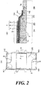
- a fuel battery cell FC illustrated in FIG. 1 is, for example, a solid oxide fuel battery, and includes a battery structure 1, a support plate 2 that is made of metal and that supports the battery structure 1, and a pair of separators 3, 3 that form a gas channel between the battery structure 1 and the support plate 2.
- This fuel battery cell FC may be referred to as a "metal-supported cell", because mechanical strength is increased while gas permeability is secured by the support plate 2.
- the battery structure 1 has a lamination of an anode electrode layer (fuel electrode layer) 4, an electrolyte layer 5 comprising solid electrolyte, and a cathode electrode layer (air electrode layer) 6 in this order, from a lower side in the figure.
- the region in which the three layers 4 to 6 overlap on one another is a power generation region G having electrochemical activity.
- the anode electrode layer 4 uses a cermet of nickel and yttria-stabilized zirconia
- the electrolyte layer 5 uses 8 mol% yttria-stabilized zirconia
- the cathode electrode layer 6 uses lanthanum strontium manganite.
- the support plate 2 made of metal may be disposed on either of the electrode layers 4 and 6 sides, when it is disposed in order to reinforce strength of the battery structure 1. However, the support plate 2 is disposed on the anode electrode layer 4 side of the battery structure 1 to prevent oxidation.
- the support plate 2 integrally includes a main body part 2A at a center and a frame part 2B at an outer periphery of the main body part 2B.
- the main body part 2A has gas permeability and is in contact with the power generation region G of the anode electrode layer 4.
- the frame part 2B has gas impermeability and has relatively a small thickness Tb with respect to the thickness Ta of the main body part 2A.
- the support plate 2 has a step surface 2D between the main body part 2A and the frame part 2B on a surface on the anode electrode layer 4 side.
- the support plate 2 of this embodiment includes an intermediate part 2C that continuously connects the main body part 2A and the frame part 2B.
- the thickness of the intermediate part 2C continuously decreases from the main body part 2A to the frame part 2B. Due to this, the step surface 2D of the support plate 2 is inclined from the main body part 2A to the frame part 2B.
- the support plate 2 is made of a porous metal material, such as foamed metal, By applying pressure to a peripheral part of the porous metal material, for example, by press working, a porous composition still remains in a center part, and it serves as the main body part 2A having gas permeability.
- the pressurized peripheral part having a dense composition serves as the frame part 2B having gas impermeability.
- the support plate 2 integrally includes the main body part 2A and the thinned frame part 2B.
- the support plate 2 of this embodiment has the intermediate part 2C and the step surface 2D on one surface side.
- the opposite surface is a flat surface, in which the main body part 2A, the intermediate part 2C, and the frame part 2B continue on the same plane.
- the electrolyte layer 5 of the battery structure 1 is disposed in a way it extends to an outer periphery side of the power generation region G and reach the step surface 2D and the frame part 2B.
- the extended part of the electrolyte layer 5 is referred to as an "outer peripheral edge part 5A".
- the anode electrode layer 4 of the battery structure 1 has an outer peripheral edge part 4A that is disposed in a way it extends to the outer periphery side of the power generation region G along the step surface 2D and the frame part 2B.
- the outer peripheral edge part 5A of the electrolyte layer 5 covers the outer peripheral edge part 4A of the anode electrode layer 4 and also covers a peripheral end surface 4E of the outer peripheral edge part 4A of the anode electrode layer 4 in the frame part 2B.
- the thickness of the anode electrode layer 4 is set such that a thermal expansion amount of the anode electrode layer 4 is equivalent to the thermal expansion amount of the intermediate part 2C of the support plate 2, and the thicknesses of the anode electrode layer 4 at the power generation region G and at the outer peripheral edge part 4A are the same.
- the thickness of the anode electrode layer 4, by which the anode electrode layer 4 has the thermal expansion amount equivalent to the thermal expansion amount of the intermediate part 2C is a thickness that provides a displacement amount equivalent to the displacement amount (deformation amount) of the intermediate part at the time the support plate 2 thermally expands.
- the cathode electrode layer 6 of the battery structure 1 is provided to the support plate 2 in a range of the main body part 2A and is provided only in the range of the main body part 2A in the example illustrated in the figure. Due to this, the fuel battery cell FC has the power generation region G, which comprises the three layers 4 to 6 of the battery structure 1, within the range of the main body part 2A of the support plate 2 and has the outer peripheral edge parts 4A and 5A of the anode electrode layer 4 and the electrolyte layer 5 disposed along the step surface 2D and the frame part 2B.
- the support plate 2 having the battery structure 1, and the pair of the separators 3, 3 have rectangular shapes with approximately the same longitudinal and lateral dimensions, as illustrated in FIG. 1 .
- a gas channel for circulating cathode gas (air) is formed between one separator 3 and the cathode electrode layer 6 of the battery structure 1 and a gas channel for circulating anode gas (fuel gas) is formed between the other separator 3 and the anode electrode layer 4 / the support plate 2.
- the fuel battery cell FC includes a manifold hole H1 for supplying the anode gas and a manifold hole H2 for discharging the cathode gas that are formed on one short side of the support plate 2 and the pair of the separators 3, 3.
- a manifold hole H3 for discharging the anode gas and a manifold hole H4 for supplying the cathode gas are formed on the other short side.
- manifold holes H1 to H4 communicate with each other to form manifolds for circulating the respective gases when the battery structure 1 and the separators 3 are laminated to assemble a fuel battery cell stack.
- the battery structures 1 adjacent in the stacking direction share one separator 3 between them.
- a sealing member S is provided between outer peripheral parts of the support plate 2 and each of the separators 3 and around the manifold holes H1 to H4, thereby air-tightness of the gas channels is secured.
- the sealing member S is not disposed around the manifold holes H1 to H4 or an open part is provided in a part of the sealing member S, in order to allow the gas corresponding to the respective gas channel to circulate.
- the fuel battery cell FC generates electrical energy due to electrochemical reaction in the power generation region G, by supplying the anode gas to the anode electrode layer 4 of the battery structure 1 and also supplying the cathode gas to the cathode electrode layer 6. At this time, the anode gas is supplied to the anode electrode layer 4 through the main body part 2A having gas permeability in the support plate 2.
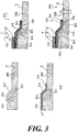
- the support plate 2 illustrated in FIG. 3A includes the main body part 2A, the frame part 2B, the intermediate part 2C, and the inclined step surface 2D that are integrally formed by applying pressure to a part of a porous metal material, as described above.
- the support plate 2 has an opposite surface with no step surface 2D, which is a flat surface on which the main body part 2A, the frame part 2B, and the intermediate part 2C continue on the same plane.
- a material for an anode electrode is applied on an upper surface of the main body part 2A, the step surface 2D, and the frame part 2B, on the surface of the support plate 2 where the step surface 2D is formed, and the anode electrode layer 4 is formed by burning this.
- the support plate 2 is heated with the periphery restricted by a jig (not illustrated).
- an electrolyte layer 5 is formed on an upper surface of the anode electrode layer 4 by sputtering, to cover the anode electrode layer 4 to its peripheral end surface 4E.
- a material for a cathode electrode is applied on an upper surface in the power generation region G of the electrolyte layer 5, and the cathode electrode layer 6 is formed by burning this.
- the support plate 2 is heated with the periphery restricted by a jig in a similar manner as described above. Then, the support plate 2 is cooled and contracts accordingly, whereby the internal stress is reset.
- the support plate 2 has a large structural change at the intermediate part 2C having the step surface 2D, due to changes in thickness, changes in void fraction (porosity), changes in strength, and heat history during the manufacturing process, and the like. Therefore, the support plate 2 generates heat and thermally expands as a whole during power generation. However, a difference in contraction amount is generated between the surface on the step surface 2D side and the opposite side surface (flat surface) after power generation is stopped.
- the support plate 2 has a greater contraction amount on the step surface 2D side than that on the opposite side surface, because the surface area on the step surface 2D side is greater than that of the opposite side surface by the amount of the step surface 2D.
- the support plate 2 is displaced (deformed) to curve in a way that the step surface 2D of the intermediate part 2C is on the inner side of the curve, as indicated by a bold arrow in FIG. 3D , in accordance with cooling after power generation is stopped.
- the electrolyte layer 5 has a relatively low resistance against a tensile load and has a relatively high resistance against a compressive load.
- the battery structure 1 is disposed on the step surface 2D side of the support plate 2 and the electrolyte layer 5 is disposed in a way it extends to the step surface 2D and the frame part 2B having gas impermeability. Therefore, although the compressive load A1 generated in the intermediate part 2C of the support plate 2 is applied to the electrolyte layer 5, the tensile load A2 is not applied thereto.
- a gas barrier property is secured at an end part of the battery structure 1 between the electrolyte layer 5 (outer peripheral edge part 5A) and the frame part 2B.
- the anode electrode layer 4 also thermally expands in addition to the support plate 2.
- the support plate 2 has an asymmetric shape relative to a center line of the thickness and has a volume of the half part having the step surface 2D smaller than the volume of the other half part.
- the support plate 2 is slightly deformed in a way that the step surface 2D is on the inner side of the deformation, and a compressive load is generated in the intermediate part 2C.
- the support plate 2 is made of a porous metal material, and the frame part 2B is formed by applying pressure to a part of the porous metal material in the thickness direction, to have a dense structure. Due to this, in the fuel battery cell FC, the support plate 2 that integrally has the main body part 2A with gas permeability and the frame part 2B with gas impermeability by using a single material. Thus, it is suitable for mass production.
- the thickness of the intermediate part 2C of the support plate 2 continuously reduces in the range from the main body part 2A to the frame part 2B, and the step surface 2D is inclined. Therefore, in the fuel battery cell FC, the structural change in the intermediate part 2C is moderated, and concentration of thermal stress is suppressed.
- the anode electrode layer 4 of the battery structure 1 has the outer peripheral edge part 4A, which is disposed along the step surface 2D and the frame part 2B, as with the electrolyte layer 5, and the peripheral end surface 4E of the outer peripheral edge part 4A of the anode electrode layer 4 is covered with the outer peripheral edge part 5A of the electrolyte layer 5 at the frame part 2B. Therefore, in the fuel battery cell FC, as described above, a force generated by thermal expansion of the anode electrode layer 4 acts in a direction of canceling the force generated in the intermediate part 2C, thereby the displacement amount of the support plate 2 can be suppressed and the gas barrier property at the end part of the battery structure 1 can be sufficiently secured.
- the thickness of the anode electrode layer 4 is set such that a thermal expansion amount of the anode electrode layer 4 is equivalent to the thermal expansion amount of the intermediate part 2C of the support plate 2. Therefore, a thermal expansion force of the anode electrode layer 4 and a compressive load of the intermediate part 2C act in a way they cancel each other, thereby displacement of the support plate 2 is suppressed. That is, in the fuel battery cell FC, while a compressive load is applied to the electrolyte layer 5, thermal expansion of the anode electrode layer 4 suppresses displacement of the support plate 2, thereby application of an excessive compressive load to the electrolyte layer 5 is prevented.
- the thicknesses of the anode electrode layer 4 is set to be the same in the power generation region G and in the outer peripheral edge part 4A. Therefore, application of an excessive compressive load to the electrolyte layer 5 is prevented, and also concentration of thermal stress due to rapid shape change in the anode electrode layer 4 is prevented.
- the cathode electrode layer 6 of the battery structure 1 is provided to the support plate 2 in the range of the main body part 2A. That is, in the fuel battery cell FC, the cathode electrode layer 6 having a large thermal expansion rate is provided only in the power generation region G of the battery structure 1, thereby preventing displacement of the cathode electrode layer 6 due to thermal expansion from affecting the intermediate part 2C (step surface 2D). Thus, a load to be applied to the end part of the battery structure 1 is reduced.
- FIGs. 4 to 7 illustrate second to fourth embodiments of the fuel battery cell of the present invention.
- the same constitutional parts as those of the first embodiment are denoted by the same reference signs, and detailed descriptions thereof are omitted.
- the fuel battery cell FC illustrated in FIG. 4 has step surfaces 2D, 2D formed by the change of the thickness of the intermediate part 2C, on both surfaces of the support plate 2. That is, the support plate 2 of this embodiment has a symmetric shape with respect to the center line of the thickness.
- the fuel battery cell FC illustrated in FIG. 5 has step surfaces 2D, 2D on both surfaces of the support plate 2.
- a step size h2 between the main body part 2A and the frame part 2B on the opposite surface side is smaller than a step size h1 between the main body part 2A and the frame part 2B on the surface where the battery structure 1 is disposed.
- the support plate 2 of this embodiment has an asymmetric shape with respect to the center line of the thickness, and although both of the step surfaces 2D, 2D are inclined, the area of the step surface 2D on the surface where the battery structure 1 is disposed is greater than the area of the step surface 2D on the opposite side, due to the difference between the step sizes h1 and h2.
- both of the contraction displacement of the support plate 2 after power generation is stopped and the thermal expansion of the support plate 2 and the anode electrode layer 4 are taken into consideration. That is, when the support plate 2 contracts after power generation is stopped, a contraction amount on the step surface 2D side having the large step size h1 is greater than the contraction amount on the step surface 2D side having the small step size h2, due to the difference in the surface areas.
- the support plate 2 is displaced to curve in a way that the step surface 2D with the large step size h1 is on the inner side of the curve, whereby a compressive load is applied to the inner inside of the curve, while a tensile load is applied to the outer side of the curve.
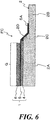
- the fuel battery cell FC illustrated in FIG. 6 differs from the fuel battery cell FC in the first embodiment (refer to FIG. 2 ) in that only the electrolyte layer 5 has the outer peripheral edge part 5A and is disposed in a way it extends to the frame part 2B, whereas the anode electrode layer 4 and the electrolyte layer 5 respectively have the outer peripheral edge parts 4A, 5A in the first embodiment.
- the fuel battery cell FC illustrated in FIG. 7 does not have the intermediate part 2C, whereas in the foregoing embodiments the support plate 2 has the intermediate part 2C and the step surface 2D. That is, the support plate 2 has a step surface 2D orthogonal in an in-plane direction between the main body part 2A and the frame part 2B that is thinner than the main body part 2A. Although the step surface 2D illustrated in the figure is orthogonal in the in-plane direction, the step surface 2D may have a slight inclination and may have a round corner.
- the support plate 2 contracts after power generation is stopped, the support plate 2 is deformed to curve in a way that the step surface 2D is on the inner side of the curve, because the surface area on the step surface 2D side is greater than that of the opposite side surface by the amount of the step surface 2D.
- the battery structure 1 is disposed on the step surface 2D side, and therefore a risk of application of a tensile load to the electrolyte layer 5 is removed, when the support plate 2 contracts after power generation is stopped, whereby occurrence of a crack and the like in the electrolyte layer 5 are prevented beforehand.
- a good gas barrier property at the end part of the battery structure 1 is maintained.
Landscapes
- Chemical & Material Sciences (AREA)
- Engineering & Computer Science (AREA)
- Chemical Kinetics & Catalysis (AREA)
- Electrochemistry (AREA)
- General Chemical & Material Sciences (AREA)
- Life Sciences & Earth Sciences (AREA)
- Manufacturing & Machinery (AREA)
- Sustainable Development (AREA)
- Sustainable Energy (AREA)
- Ceramic Engineering (AREA)
- Fuel Cell (AREA)
Claims (7)
- Brennstoffbatteriezelle, die eine Batteriestruktur und eine Trägerplatte umfasst,
wobei die Batteriestruktur einen Stromerzeugungs-Bereich mit einer Schichtanordnung aus einer Anoden-Elektrodenschicht, einer Elektrolytschicht und einer Kathoden-Elektrodenschicht aufweist, und
die Trägerplatte aus Metall besteht und an der Seite der Anoden-Elektrodenschicht der Batteriestruktur angeordnet ist, um die Batteriestruktur zu tragen,
wobei
die Trägerplatte integral einen Hauptkörperteil in einer Mitte und einen Rahmenteil an einem Außenumfang des Hauptkörperteils umfasst, wobei der Hauptkörperteil Gasdurchlässigkeit aufweist und in Kontakt mit dem Stromerzeugungs-Bereich der Anoden-Elektrodenschicht ist, und der Rahmenteil Gasundurchlässigkeit aufweist und seine Dicke vergleichsweise geringer ist als eine Dicke des Hauptkörperteils,
die Trägerplatte eine Absatzfläche zwischen dem Hauptkörperteil und dem Rahmenteil an einer Fläche an der Seite der Anoden-Elektrodenschicht aufweist, und
die Elektrolytschicht der Batteriestruktur so angeordnet ist, dass sie sich zu einer Außenumfangsseite des Stromerzeugungsbereiches erstreckt und bis zu der Absatzfläche und dem Rahmenteil reicht. - Brennstoffbatteriezelle nach Anspruch 1, wobei die Trägerplatte einen Zwischenteil aufweist, dessen Dicke von dem Hauptkörperteil bis zu dem Rahmenteil kontinuierlich abnimmt, und die Absatzfläche von dem Hauptkörperteil zu dem Rahmenteil geneigt ist.
- Brennstoffbatteriezelle nach Anspruch 1 oder 2, wobei die Anoden-Elektrodenschicht der Batteriestruktur einen Außenumfangs-Randteil enthält, der so angeordnet ist, dass er sich entlang der Absatzfläche und des Rahmenteils bis zu der Außenumfangsseite des Stromerzeugungsbereiches erstreckt, und die Elektrolytschicht den Außenumfangs-Randteil der Anoden-Elektrodenschicht und ihre Umfangs-Endfläche abdeckt.
- Brennstoffbatteriezelle nach Anspruch 3, wobei die Trägerplatte einen Zwischenteil aufweist, dessen Dicke von dem Hauptkörperteil bis zu dem Rahmenteil kontinuierlich abnimmt, die Absatzfläche von dem Hauptkörperteil zu dem Rahmenteil geneigt ist, und
die Dicke der Anoden-Elektrodenschicht so festgelegt ist, dass ein Maß von Wärmeausdehnung der Anoden-Elektrodenschicht äquivalent zu einem Maß von Wärmeausdehnung des Zwischenteils ist. - Brennstoffbatteriezelle nach Anspruch 3 oder 4, wobei die Dicken der Anoden-Elektrodenschicht in dem Stromerzeugungs-Bereich und in dem Außenumfangs-Randteil derselben gleich sind.
- Brennstoffbatteriezelle nach einem der Ansprüche 1 bis 5, wobei die Kathoden-Elektrodenschicht in einem Bereich des Hauptkörperteils in Bezug auf die Trägerplatte vorhanden ist.
- Brennstoffbatteriezelle nach einem der Ansprüche 1 bis 6, wobei die Trägerplatte die Absatzfläche an beiden Oberflächen aufweist und eine Größe des Absatzes zwischen dem Hauptkörperteil und dem Rahmenteil an der Seite einer Oberfläche, die der Seite einer Oberfläche gegenüberliegt, an der die Batteriestruktur angeordnet ist, kleiner ist als eine Größe des Absatzes zwischen dem Hauptkörperteil und dem Rahmenteil an der Seite einer Oberfläche, an der die Batteriestruktur angeordnet ist.
Applications Claiming Priority (1)
| Application Number | Priority Date | Filing Date | Title |
|---|---|---|---|
| PCT/JP2017/027733 WO2019026138A1 (ja) | 2017-07-31 | 2017-07-31 | 燃料電池セル |
Publications (3)
| Publication Number | Publication Date |
|---|---|
| EP3664201A1 EP3664201A1 (de) | 2020-06-10 |
| EP3664201A4 EP3664201A4 (de) | 2020-08-19 |
| EP3664201B1 true EP3664201B1 (de) | 2020-12-16 |
Family
ID=65232414
Family Applications (1)
| Application Number | Title | Priority Date | Filing Date |
|---|---|---|---|
| EP17920196.7A Active EP3664201B1 (de) | 2017-07-31 | 2017-07-31 | Kraftstoffzelle |
Country Status (5)
| Country | Link |
|---|---|
| US (1) | US10978714B2 (de) |
| EP (1) | EP3664201B1 (de) |
| JP (1) | JP6856125B2 (de) |
| CN (1) | CN110945698B (de) |
| WO (1) | WO2019026138A1 (de) |
Family Cites Families (7)
| Publication number | Priority date | Publication date | Assignee | Title |
|---|---|---|---|---|
| DE10135333A1 (de) * | 2001-07-19 | 2003-02-06 | Elringklinger Ag | Brennstoffzelleneinheit |
| JP4232614B2 (ja) * | 2003-11-20 | 2009-03-04 | 日産自動車株式会社 | 固体電解質型燃料電池 |
| DE102007034967A1 (de) * | 2007-07-26 | 2009-01-29 | Plansee Se | Brennstoffzelle und Verfahren zu deren Herstellung |
| US20100190084A1 (en) * | 2007-11-28 | 2010-07-29 | Toyota Jidosha Kabushiki Kaisha | Single fuel cell |
| JP5335068B2 (ja) | 2008-04-18 | 2013-11-06 | ザ、リージェンツ、オブ、ザ、ユニバーシティ、オブ、カリフォルニア | 電気化学装置構成及びその製法 |
| DE102013008473A1 (de) * | 2013-05-21 | 2014-11-27 | Plansee Composite Materials Gmbh | Brennstoffzelle |
| JP6128353B2 (ja) * | 2013-08-08 | 2017-05-17 | 日産自動車株式会社 | フレーム付き膜電極接合体、燃料電池用単セル及び燃料電池スタック |
-
2017
- 2017-07-31 WO PCT/JP2017/027733 patent/WO2019026138A1/ja active Application Filing
- 2017-07-31 US US16/634,676 patent/US10978714B2/en active Active
- 2017-07-31 CN CN201780093448.4A patent/CN110945698B/zh active Active
- 2017-07-31 EP EP17920196.7A patent/EP3664201B1/de active Active
- 2017-07-31 JP JP2019533745A patent/JP6856125B2/ja active Active
Non-Patent Citations (1)
| Title |
|---|
| None * |
Also Published As
| Publication number | Publication date |
|---|---|
| CN110945698B (zh) | 2020-10-13 |
| US20200381740A1 (en) | 2020-12-03 |
| JPWO2019026138A1 (ja) | 2020-07-30 |
| US10978714B2 (en) | 2021-04-13 |
| CN110945698A (zh) | 2020-03-31 |
| WO2019026138A1 (ja) | 2019-02-07 |
| EP3664201A1 (de) | 2020-06-10 |
| JP6856125B2 (ja) | 2021-04-07 |
| EP3664201A4 (de) | 2020-08-19 |
Similar Documents
| Publication | Publication Date | Title |
|---|---|---|
| EP2586088B1 (de) | Brennstoffzelle | |
| JP2013058464A (ja) | サンドイッチインサートを有する燃料電池用エンドプレート | |
| KR20210018421A (ko) | 누출이 감소된 단위 셀을 가진 고체 산화물 연료 전지 스택 | |
| KR20160074608A (ko) | 세퍼레이터가 부착된 연료 전지 단셀, 및 연료 전지 스택 | |
| JP6199697B2 (ja) | セパレータ付燃料電池単セル,燃料電池スタック,およびその製造方法 | |
| US9478812B1 (en) | Interconnect for fuel cell stack | |
| WO2015049859A1 (ja) | 燃料電池用セパレーターおよび燃料電池 | |
| JP2008010350A5 (de) | ||
| JP2008034274A (ja) | 燃料電池用セパレータ及び燃料電池用セパレータ構成用プレート及び燃料電池用セパレータの製造方法 | |
| EP3664201B1 (de) | Kraftstoffzelle | |
| US8383282B2 (en) | Contact arrangement and method for assembling a fuel cell stack from at least one contact arrangement | |
| JP5125217B2 (ja) | 燃料電池 | |
| EP3664202B1 (de) | Zelleneinheit | |
| US11271221B2 (en) | Electrochemical reaction cell stack, interconnector-electrochemical reaction unit cell composite, and method for manufacturing electrochemical reaction cell stack | |
| JP3487884B2 (ja) | 溶融炭酸塩型積層型燃料電池 | |
| CN110663130B (zh) | 燃料电池单元 | |
| CA2980973C (en) | Arrangement of electrochemical cells and the use of same | |
| JP5727429B2 (ja) | セパレータ付燃料電池セル,および燃料電池 | |
| JP2019009083A (ja) | 電気化学反応単セルおよび電気化学反応セルスタック | |
| JP6927309B2 (ja) | 燃料電池のスタック構造および燃料電池スタックの熱歪吸収方法 | |
| JP6740856B2 (ja) | 燃料電池及び燃料電池の製造方法 | |
| US20180219244A1 (en) | Fuel cell stack |
Legal Events
| Date | Code | Title | Description |
|---|---|---|---|
| STAA | Information on the status of an ep patent application or granted ep patent |
Free format text: STATUS: THE INTERNATIONAL PUBLICATION HAS BEEN MADE |
|
| PUAI | Public reference made under article 153(3) epc to a published international application that has entered the european phase |
Free format text: ORIGINAL CODE: 0009012 |
|
| STAA | Information on the status of an ep patent application or granted ep patent |
Free format text: STATUS: REQUEST FOR EXAMINATION WAS MADE |
|
| 17P | Request for examination filed |
Effective date: 20200226 |
|
| AK | Designated contracting states |
Kind code of ref document: A1 Designated state(s): AL AT BE BG CH CY CZ DE DK EE ES FI FR GB GR HR HU IE IS IT LI LT LU LV MC MK MT NL NO PL PT RO RS SE SI SK SM TR |
|
| AX | Request for extension of the european patent |
Extension state: BA ME |
|
| A4 | Supplementary search report drawn up and despatched |
Effective date: 20200716 |
|
| RIC1 | Information provided on ipc code assigned before grant |
Ipc: H01M 8/12 20160101ALI20200710BHEP Ipc: H01M 8/02 20160101AFI20200710BHEP |
|
| GRAP | Despatch of communication of intention to grant a patent |
Free format text: ORIGINAL CODE: EPIDOSNIGR1 |
|
| STAA | Information on the status of an ep patent application or granted ep patent |
Free format text: STATUS: GRANT OF PATENT IS INTENDED |
|
| RIC1 | Information provided on ipc code assigned before grant |
Ipc: H01M 8/124 20160101ALN20200909BHEP Ipc: H01M 8/0273 20160101ALI20200909BHEP Ipc: H01M 8/12 20160101ALI20200909BHEP Ipc: H01M 8/02 20160101AFI20200909BHEP |
|
| DAV | Request for validation of the european patent (deleted) | ||
| DAX | Request for extension of the european patent (deleted) | ||
| INTG | Intention to grant announced |
Effective date: 20200923 |
|
| GRAS | Grant fee paid |
Free format text: ORIGINAL CODE: EPIDOSNIGR3 |
|
| GRAA | (expected) grant |
Free format text: ORIGINAL CODE: 0009210 |
|
| STAA | Information on the status of an ep patent application or granted ep patent |
Free format text: STATUS: THE PATENT HAS BEEN GRANTED |
|
| AK | Designated contracting states |
Kind code of ref document: B1 Designated state(s): AL AT BE BG CH CY CZ DE DK EE ES FI FR GB GR HR HU IE IS IT LI LT LU LV MC MK MT NL NO PL PT RO RS SE SI SK SM TR |
|
| REG | Reference to a national code |
Ref country code: GB Ref legal event code: FG4D |
|
| REG | Reference to a national code |
Ref country code: DE Ref legal event code: R096 Ref document number: 602017029837 Country of ref document: DE |
|
| REG | Reference to a national code |
Ref country code: IE Ref legal event code: FG4D |
|
| REG | Reference to a national code |
Ref country code: AT Ref legal event code: REF Ref document number: 1346412 Country of ref document: AT Kind code of ref document: T Effective date: 20210115 |
|
| PG25 | Lapsed in a contracting state [announced via postgrant information from national office to epo] |
Ref country code: GR Free format text: LAPSE BECAUSE OF FAILURE TO SUBMIT A TRANSLATION OF THE DESCRIPTION OR TO PAY THE FEE WITHIN THE PRESCRIBED TIME-LIMIT Effective date: 20210317 Ref country code: NO Free format text: LAPSE BECAUSE OF FAILURE TO SUBMIT A TRANSLATION OF THE DESCRIPTION OR TO PAY THE FEE WITHIN THE PRESCRIBED TIME-LIMIT Effective date: 20210316 Ref country code: RS Free format text: LAPSE BECAUSE OF FAILURE TO SUBMIT A TRANSLATION OF THE DESCRIPTION OR TO PAY THE FEE WITHIN THE PRESCRIBED TIME-LIMIT Effective date: 20201216 Ref country code: FI Free format text: LAPSE BECAUSE OF FAILURE TO SUBMIT A TRANSLATION OF THE DESCRIPTION OR TO PAY THE FEE WITHIN THE PRESCRIBED TIME-LIMIT Effective date: 20201216 |
|
| REG | Reference to a national code |
Ref country code: AT Ref legal event code: MK05 Ref document number: 1346412 Country of ref document: AT Kind code of ref document: T Effective date: 20201216 |
|
| REG | Reference to a national code |
Ref country code: NL Ref legal event code: MP Effective date: 20201216 |
|
| PG25 | Lapsed in a contracting state [announced via postgrant information from national office to epo] |
Ref country code: BG Free format text: LAPSE BECAUSE OF FAILURE TO SUBMIT A TRANSLATION OF THE DESCRIPTION OR TO PAY THE FEE WITHIN THE PRESCRIBED TIME-LIMIT Effective date: 20210316 Ref country code: LV Free format text: LAPSE BECAUSE OF FAILURE TO SUBMIT A TRANSLATION OF THE DESCRIPTION OR TO PAY THE FEE WITHIN THE PRESCRIBED TIME-LIMIT Effective date: 20201216 Ref country code: SE Free format text: LAPSE BECAUSE OF FAILURE TO SUBMIT A TRANSLATION OF THE DESCRIPTION OR TO PAY THE FEE WITHIN THE PRESCRIBED TIME-LIMIT Effective date: 20201216 |
|
| PG25 | Lapsed in a contracting state [announced via postgrant information from national office to epo] |
Ref country code: NL Free format text: LAPSE BECAUSE OF FAILURE TO SUBMIT A TRANSLATION OF THE DESCRIPTION OR TO PAY THE FEE WITHIN THE PRESCRIBED TIME-LIMIT Effective date: 20201216 Ref country code: HR Free format text: LAPSE BECAUSE OF FAILURE TO SUBMIT A TRANSLATION OF THE DESCRIPTION OR TO PAY THE FEE WITHIN THE PRESCRIBED TIME-LIMIT Effective date: 20201216 |
|
| REG | Reference to a national code |
Ref country code: LT Ref legal event code: MG9D |
|
| PG25 | Lapsed in a contracting state [announced via postgrant information from national office to epo] |
Ref country code: SK Free format text: LAPSE BECAUSE OF FAILURE TO SUBMIT A TRANSLATION OF THE DESCRIPTION OR TO PAY THE FEE WITHIN THE PRESCRIBED TIME-LIMIT Effective date: 20201216 Ref country code: RO Free format text: LAPSE BECAUSE OF FAILURE TO SUBMIT A TRANSLATION OF THE DESCRIPTION OR TO PAY THE FEE WITHIN THE PRESCRIBED TIME-LIMIT Effective date: 20201216 Ref country code: PT Free format text: LAPSE BECAUSE OF FAILURE TO SUBMIT A TRANSLATION OF THE DESCRIPTION OR TO PAY THE FEE WITHIN THE PRESCRIBED TIME-LIMIT Effective date: 20210416 Ref country code: SM Free format text: LAPSE BECAUSE OF FAILURE TO SUBMIT A TRANSLATION OF THE DESCRIPTION OR TO PAY THE FEE WITHIN THE PRESCRIBED TIME-LIMIT Effective date: 20201216 Ref country code: EE Free format text: LAPSE BECAUSE OF FAILURE TO SUBMIT A TRANSLATION OF THE DESCRIPTION OR TO PAY THE FEE WITHIN THE PRESCRIBED TIME-LIMIT Effective date: 20201216 Ref country code: CZ Free format text: LAPSE BECAUSE OF FAILURE TO SUBMIT A TRANSLATION OF THE DESCRIPTION OR TO PAY THE FEE WITHIN THE PRESCRIBED TIME-LIMIT Effective date: 20201216 Ref country code: LT Free format text: LAPSE BECAUSE OF FAILURE TO SUBMIT A TRANSLATION OF THE DESCRIPTION OR TO PAY THE FEE WITHIN THE PRESCRIBED TIME-LIMIT Effective date: 20201216 |
|
| PG25 | Lapsed in a contracting state [announced via postgrant information from national office to epo] |
Ref country code: PL Free format text: LAPSE BECAUSE OF FAILURE TO SUBMIT A TRANSLATION OF THE DESCRIPTION OR TO PAY THE FEE WITHIN THE PRESCRIBED TIME-LIMIT Effective date: 20201216 Ref country code: AT Free format text: LAPSE BECAUSE OF FAILURE TO SUBMIT A TRANSLATION OF THE DESCRIPTION OR TO PAY THE FEE WITHIN THE PRESCRIBED TIME-LIMIT Effective date: 20201216 |
|
| REG | Reference to a national code |
Ref country code: DE Ref legal event code: R097 Ref document number: 602017029837 Country of ref document: DE |
|
| PG25 | Lapsed in a contracting state [announced via postgrant information from national office to epo] |
Ref country code: IS Free format text: LAPSE BECAUSE OF FAILURE TO SUBMIT A TRANSLATION OF THE DESCRIPTION OR TO PAY THE FEE WITHIN THE PRESCRIBED TIME-LIMIT Effective date: 20210416 |
|
| PLBE | No opposition filed within time limit |
Free format text: ORIGINAL CODE: 0009261 |
|
| STAA | Information on the status of an ep patent application or granted ep patent |
Free format text: STATUS: NO OPPOSITION FILED WITHIN TIME LIMIT |
|
| PG25 | Lapsed in a contracting state [announced via postgrant information from national office to epo] |
Ref country code: AL Free format text: LAPSE BECAUSE OF FAILURE TO SUBMIT A TRANSLATION OF THE DESCRIPTION OR TO PAY THE FEE WITHIN THE PRESCRIBED TIME-LIMIT Effective date: 20201216 Ref country code: IT Free format text: LAPSE BECAUSE OF FAILURE TO SUBMIT A TRANSLATION OF THE DESCRIPTION OR TO PAY THE FEE WITHIN THE PRESCRIBED TIME-LIMIT Effective date: 20201216 |
|
| 26N | No opposition filed |
Effective date: 20210917 |
|
| PG25 | Lapsed in a contracting state [announced via postgrant information from national office to epo] |
Ref country code: DK Free format text: LAPSE BECAUSE OF FAILURE TO SUBMIT A TRANSLATION OF THE DESCRIPTION OR TO PAY THE FEE WITHIN THE PRESCRIBED TIME-LIMIT Effective date: 20201216 |
|
| PG25 | Lapsed in a contracting state [announced via postgrant information from national office to epo] |
Ref country code: ES Free format text: LAPSE BECAUSE OF FAILURE TO SUBMIT A TRANSLATION OF THE DESCRIPTION OR TO PAY THE FEE WITHIN THE PRESCRIBED TIME-LIMIT Effective date: 20201216 |
|
| REG | Reference to a national code |
Ref country code: CH Ref legal event code: PL |
|
| PG25 | Lapsed in a contracting state [announced via postgrant information from national office to epo] |
Ref country code: MC Free format text: LAPSE BECAUSE OF FAILURE TO SUBMIT A TRANSLATION OF THE DESCRIPTION OR TO PAY THE FEE WITHIN THE PRESCRIBED TIME-LIMIT Effective date: 20201216 |
|
| REG | Reference to a national code |
Ref country code: BE Ref legal event code: MM Effective date: 20210731 |
|
| PG25 | Lapsed in a contracting state [announced via postgrant information from national office to epo] |
Ref country code: LI Free format text: LAPSE BECAUSE OF NON-PAYMENT OF DUE FEES Effective date: 20210731 Ref country code: CH Free format text: LAPSE BECAUSE OF NON-PAYMENT OF DUE FEES Effective date: 20210731 |
|
| PG25 | Lapsed in a contracting state [announced via postgrant information from national office to epo] |
Ref country code: IS Free format text: LAPSE BECAUSE OF FAILURE TO SUBMIT A TRANSLATION OF THE DESCRIPTION OR TO PAY THE FEE WITHIN THE PRESCRIBED TIME-LIMIT Effective date: 20210416 Ref country code: LU Free format text: LAPSE BECAUSE OF NON-PAYMENT OF DUE FEES Effective date: 20210731 |
|
| PG25 | Lapsed in a contracting state [announced via postgrant information from national office to epo] |
Ref country code: IE Free format text: LAPSE BECAUSE OF NON-PAYMENT OF DUE FEES Effective date: 20210731 Ref country code: BE Free format text: LAPSE BECAUSE OF NON-PAYMENT OF DUE FEES Effective date: 20210731 |
|
| PG25 | Lapsed in a contracting state [announced via postgrant information from national office to epo] |
Ref country code: CY Free format text: LAPSE BECAUSE OF FAILURE TO SUBMIT A TRANSLATION OF THE DESCRIPTION OR TO PAY THE FEE WITHIN THE PRESCRIBED TIME-LIMIT Effective date: 20201216 |
|
| PG25 | Lapsed in a contracting state [announced via postgrant information from national office to epo] |
Ref country code: HU Free format text: LAPSE BECAUSE OF FAILURE TO SUBMIT A TRANSLATION OF THE DESCRIPTION OR TO PAY THE FEE WITHIN THE PRESCRIBED TIME-LIMIT; INVALID AB INITIO Effective date: 20170731 |
|
| PGFP | Annual fee paid to national office [announced via postgrant information from national office to epo] |
Ref country code: FR Payment date: 20230621 Year of fee payment: 7 |
|
| REG | Reference to a national code |
Ref country code: DE Ref legal event code: R084 Ref document number: 602017029837 Country of ref document: DE |
|
| PG25 | Lapsed in a contracting state [announced via postgrant information from national office to epo] |
Ref country code: SI Free format text: LAPSE BECAUSE OF FAILURE TO SUBMIT A TRANSLATION OF THE DESCRIPTION OR TO PAY THE FEE WITHIN THE PRESCRIBED TIME-LIMIT Effective date: 20201216 |
|
| REG | Reference to a national code |
Ref country code: GB Ref legal event code: 746 Effective date: 20230925 |
|
| PGFP | Annual fee paid to national office [announced via postgrant information from national office to epo] |
Ref country code: GB Payment date: 20230620 Year of fee payment: 7 |
|
| PGFP | Annual fee paid to national office [announced via postgrant information from national office to epo] |
Ref country code: DE Payment date: 20230620 Year of fee payment: 7 |
|
| PG25 | Lapsed in a contracting state [announced via postgrant information from national office to epo] |
Ref country code: MK Free format text: LAPSE BECAUSE OF FAILURE TO SUBMIT A TRANSLATION OF THE DESCRIPTION OR TO PAY THE FEE WITHIN THE PRESCRIBED TIME-LIMIT Effective date: 20201216 |