EP3663897A1 - Informationseingabevorrichtung - Google Patents
Informationseingabevorrichtung Download PDFInfo
- Publication number
- EP3663897A1 EP3663897A1 EP19209123.9A EP19209123A EP3663897A1 EP 3663897 A1 EP3663897 A1 EP 3663897A1 EP 19209123 A EP19209123 A EP 19209123A EP 3663897 A1 EP3663897 A1 EP 3663897A1
- Authority
- EP
- European Patent Office
- Prior art keywords
- input
- information
- touch
- corrector
- distance
- Prior art date
- Legal status (The legal status is an assumption and is not a legal conclusion. Google has not performed a legal analysis and makes no representation as to the accuracy of the status listed.)
- Granted
Links
Images







Classifications
-
- G—PHYSICS
- G06—COMPUTING OR CALCULATING; COUNTING
- G06F—ELECTRIC DIGITAL DATA PROCESSING
- G06F3/00—Input arrangements for transferring data to be processed into a form capable of being handled by the computer; Output arrangements for transferring data from processing unit to output unit, e.g. interface arrangements
- G06F3/01—Input arrangements or combined input and output arrangements for interaction between user and computer
- G06F3/03—Arrangements for converting the position or the displacement of a member into a coded form
- G06F3/041—Digitisers, e.g. for touch screens or touch pads, characterised by the transducing means
- G06F3/0416—Control or interface arrangements specially adapted for digitisers
- G06F3/0418—Control or interface arrangements specially adapted for digitisers for error correction or compensation, e.g. based on parallax, calibration or alignment
- G06F3/04186—Touch location disambiguation
-
- G—PHYSICS
- G06—COMPUTING OR CALCULATING; COUNTING
- G06F—ELECTRIC DIGITAL DATA PROCESSING
- G06F3/00—Input arrangements for transferring data to be processed into a form capable of being handled by the computer; Output arrangements for transferring data from processing unit to output unit, e.g. interface arrangements
- G06F3/01—Input arrangements or combined input and output arrangements for interaction between user and computer
- G06F3/03—Arrangements for converting the position or the displacement of a member into a coded form
- G06F3/041—Digitisers, e.g. for touch screens or touch pads, characterised by the transducing means
- G06F3/0412—Digitisers structurally integrated in a display
-
- G—PHYSICS
- G06—COMPUTING OR CALCULATING; COUNTING
- G06F—ELECTRIC DIGITAL DATA PROCESSING
- G06F3/00—Input arrangements for transferring data to be processed into a form capable of being handled by the computer; Output arrangements for transferring data from processing unit to output unit, e.g. interface arrangements
- G06F3/01—Input arrangements or combined input and output arrangements for interaction between user and computer
- G06F3/011—Arrangements for interaction with the human body, e.g. for user immersion in virtual reality
- G06F3/013—Eye tracking input arrangements
-
- G—PHYSICS
- G06—COMPUTING OR CALCULATING; COUNTING
- G06F—ELECTRIC DIGITAL DATA PROCESSING
- G06F3/00—Input arrangements for transferring data to be processed into a form capable of being handled by the computer; Output arrangements for transferring data from processing unit to output unit, e.g. interface arrangements
- G06F3/01—Input arrangements or combined input and output arrangements for interaction between user and computer
- G06F3/03—Arrangements for converting the position or the displacement of a member into a coded form
- G06F3/041—Digitisers, e.g. for touch screens or touch pads, characterised by the transducing means
- G06F3/0416—Control or interface arrangements specially adapted for digitisers
- G06F3/0418—Control or interface arrangements specially adapted for digitisers for error correction or compensation, e.g. based on parallax, calibration or alignment
-
- G—PHYSICS
- G06—COMPUTING OR CALCULATING; COUNTING
- G06F—ELECTRIC DIGITAL DATA PROCESSING
- G06F3/00—Input arrangements for transferring data to be processed into a form capable of being handled by the computer; Output arrangements for transferring data from processing unit to output unit, e.g. interface arrangements
- G06F3/01—Input arrangements or combined input and output arrangements for interaction between user and computer
- G06F3/048—Interaction techniques based on graphical user interfaces [GUI]
- G06F3/0487—Interaction techniques based on graphical user interfaces [GUI] using specific features provided by the input device, e.g. functions controlled by the rotation of a mouse with dual sensing arrangements, or of the nature of the input device, e.g. tap gestures based on pressure sensed by a digitiser
- G06F3/0488—Interaction techniques based on graphical user interfaces [GUI] using specific features provided by the input device, e.g. functions controlled by the rotation of a mouse with dual sensing arrangements, or of the nature of the input device, e.g. tap gestures based on pressure sensed by a digitiser using a touch-screen or digitiser, e.g. input of commands through traced gestures
- G06F3/04883—Interaction techniques based on graphical user interfaces [GUI] using specific features provided by the input device, e.g. functions controlled by the rotation of a mouse with dual sensing arrangements, or of the nature of the input device, e.g. tap gestures based on pressure sensed by a digitiser using a touch-screen or digitiser, e.g. input of commands through traced gestures for inputting data by handwriting, e.g. gesture or text
Definitions
- the present disclosure relates to an information input device, and more particularly, the present disclosure is applicable to an information input device including a touch surface and a display surface.
- a display device with a touch detection function that enables information input by mounting a touch detection device such as a touch panel on a display screen of a display device such as a liquid crystal display device, or integrating a touch detection device and a display screen of a display device to display various button images for information input on a display screen of a display device.
- a display device with a touch detection function is used in, for example, a portable information terminal such as a tablet-type computer or a smart phone, a car navigation device, a game machine, a vending machine, an electronic bulletin board machine, and the like.
- a portable information terminal such as a tablet-type computer or a smart phone, a car navigation device, a game machine, a vending machine, an electronic bulletin board machine, and the like.
- JP-A-2017-199062 JP-A-2018-60404 disclosed.
- a touch surface on which touch detection is performed and a display surface on which button images and the like are displayed are different from each other. That is, in terms of the structure of the device, the touch surface and the display surface do not necessarily coincide with each other in the depth direction, i.e., the direction perpendicular to the display surface. For this reason, depending on the device structure and the viewpoint of the operator, "the position (expected value) of the finger with respect to the display surface viewed from the operator” and “the coordinates (detected value) of the touch point detected by the touch device” may not coincide with each other. In particular, the deviation between the expected value and the detected value increases as the straight line connecting the viewpoint of the operator and the finger of the operator deviates from the perpendicular to the display surface. This deviation may cause discomfort and stress to the operator.
- the touch surface is formed of a curved surface
- a protective panel is provided on the touch surface, or when there is a space or a layer for radiating heat or absorbing shock between the display surface and the touch surface, the deviation between the expected value and the detected value becomes larger as the finger and the display surface are separated from each other, and there is a possibility that the operation is uncomfortable or hindered.
- the information input device includes a first surface for displaying input request information, a second surface for inputting input request information, a detector for detecting a viewpoint of an input person, and a corrector for converting information input to the second surface into information of the first surface in response to a detected viewpoint of the input person.
- FIG. 1 is a diagram illustrating a schematic configuration of an information input device according to an embodiment of the present invention.
- the information input device 1 includes a display device 2, a touch detection device 3, a protective layer 4, a detector 5, a storage device 6, and a corrector 7.
- the display device 2 has a display surface 2a for displaying input request information.
- the display device 2 can be configured by, for example, a display device such as a liquid crystal display device or an organic electroluminescence display device.
- the input request information may be, for example, a button, an icon, or a character string indicating a link destination.
- the touch detection device 3 is a device for detecting touch operations by fingers or pens.
- the touch detection device 3 can be configured by a touch panel, a touch sensor, a touch device, or the like.
- the protection layer 4 is a protective layer for protecting the touch detection device 3.
- the protection layer 4 has a touch-sensitive surface (second surface) 4a for inputting input request information.
- the protection layer 4 can be made of acrylic resin, glass, or the like.
- the touch detection device 3 detects the position Af of the operator A's finger with respect to the touch surface 4a. In this case, the touch coordinate P corresponds to the actual detection values detected by the touch detection device 3.
- the detector 5 detects the direction Ae of the viewpoint of the operator A and the position of the face or eyes of the operator A.
- the detector 5 can be composed of an imaging device such as cameras.
- the storage device 6 is a storage unit that holds in advance the distance information d of a plurality of points between the touch surface 4a and the display surface 2a as a distance map.
- the storage device 6 can be configured by a nonvolatile storage device such as an EEPROM, an EPROM, a ROM, or a flash memory, for example.
- the distance information d may be generated in advance as a design value at the time of design of the information input device 1 and stored in the storage device 6.
- the corrector 7 corrections the touch coordinates P detected by the touch detection device 3 to the touch coordinates P' based on the information of the viewpoint (face or eye position) of the operator acquired by the detector 5 and the distance information d of the touch surface 4a and the display surface 2a from the storage device 6.
- the touch coordinate P' is input to the system provided with the information input device 1.
- the touch coordinate P' is the touch coordinate (expected value) seen from the operator A.
- Buttons are displayed at the position of the coordinate P' on the display surface 2a of the display device 2.
- the operator A When pressing the button displayed at the position of the coordinate P', the operator A first points the line of sight to the button, and then presses the touch surface 4a with the fingertip.
- a button is displayed on the extension line of the direction Ae from the viewpoint of the operator A, and the fingertip is moved to the position of the button. Therefore, the position Af of the fingertip of the operator A is also on the extension line of the direction Ae from the viewpoint of the operator A.
- the touch detection device 3 detects the position Af of the fingertip of the operator A as the coordinate P. Therefore, the operator A cannot select the button displayed at the position of the coordinate P'.
- the corrector 7 corrections the touch coordinates P detected by the touch detection device 3 to the touch coordinates P' based on the information of the viewpoint (face/eye position) of the operator acquired by the detector 5 and the distance information d from the storage device 6.
- a touch operation with high accuracy can be realized.
- the uncomfortable feeling and stress on the operator can be solved.
- even when the touch surface is formed of a curved surface the possibility of causing a sense of discomfort or trouble in the operation can be reduced.
- FIG. 2 is a diagram illustrating the configuration of the information input device according to Embodiment 1.
- FIG. 3 is a diagram illustrating an example of an input condition of an operator.
- the information input device 1 includes a display device 2, a display information generator 21, a touch detection device 3, a detector 5, a storage device 6, and a corrector 7.
- the corrector 7 includes an image recognition unit 71, a viewpoint direction calculator 72, and a coordinate corrector 73.
- the protection layer 4 is omitted.
- the display device 2, the touch detection device 3, the detector 5, and the storage device 6 are the same as those in the embodiment, and their descriptions are omitted.
- the image recognizing unit 71 receives captured image CIMG of the face, eyes, and the like of the operator A from the detector 5.
- the captured image CIMG is configured by, for example, a horizontal coordinate X and a vertical coordinate Y, and a plurality of pixels constituting the image can be identified by the horizontal coordinate X and the vertical coordinate Y.
- the image recognition unit 71 detects the face, eyes, and the like of the operator A from the captured image CIMG, and extracts coordinate information of the face and eyes on the image. By this coordinate information, coordinate information of the center of the face or eye and information of the size of the face or eye can be obtained.
- the distance (depth) may be determined from the size of the face in the input image from the camera in the case of a monocular camera.
- a technique capable of simultaneously obtaining image information of an object and distance information of the object such as a ToF (Time of Flight) camera, may be used.
- a method other than the camera infrared ray, voice, ultrasonic wave, or the like
- a method other than the camera voice, ultrasonic wave, or the like
- the camera may be used in combination.
- the viewpoint direction calculator 72 receives the coordinate information of the face and the eyes on the image from the image recognition unit 71, and calculates the viewpoint direction of the operator from the coordinate information of the face and the eyes. For example, in the case of the condition shown in FIG. 3 , the viewpoint direction calculator 72 calculates the viewpoint direction of the operator A as an azimuth angle ( ⁇ ) and an elevation angle ( ⁇ ). The azimuth angle ( ⁇ ) and the elevation angle ( ⁇ ) calculated by the viewpoint direction calculator 72 are input to the coordinate corrector 73 as ( ⁇ , ⁇ ).
- the coordinate corrector 73 refers to the distance map stored in the storage device 6 based on the touch coordinates P detected by the touch detection device 3, and obtains the distance information d between the touch surface 4a and the display surface 2a.
- the coordinate corrector 73 refers to the distance map stored in the storage device 6 based on the touch coordinates P(x1, y1) detected by the touch detection device 3, and obtains the distance information d(x1, y1) between the touch surface 4a and the display surface 2a.
- the spatial coordinates of the operator A's fingers with respect to the display surface 2a are represented as (x1, y1, d).
- the coordinate corrector 73 calculates a point P' (x2, y2) on the display surface 2a obtained by extending the spatial coordinates (x1, y1, d) of the operator's fingers from the viewpoint directions ( ⁇ , ⁇ ) of the operator A as the coordinates after correction.
- the display information generator 21 selects the input request information (buttons) BT to be displayed on the coordinates (x2, y2) in the display information DI of the display device 2.
- the input request information (button) BT intended by the operator A can be selected without causing the operator A to feel discomfort and stress.
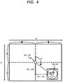
- FIG. 4 is a diagram illustrating a method of calculating the azimuth angle ( ⁇ ).
- Figs. 5 and 6 are diagrams illustrating a method of calculating the elevation angle ( ⁇ ).
- FIG. 5 shows the plan view of the captured images
- FIG. 6 is a side view of FIG. 5 as viewed laterally.
- the calculation of the viewpoint direction can be simplified when the camera (5) is also approximated to exist at the center of the display surface 2a.
- the image recognition unit 71 extracts coordinate information (center and size) of the face or eye of the operator A from the captured image.
- the viewpoint direction calculator 72 obtains the direction (azimuth angle ( ⁇ )) of the center coordinates (tx, ty) of the "face” or the "eyes" from the center (cx, cy) of the captured image, and a value (elevation angle ( ⁇ )) obtained by converting the distance into an angle.
- the azimuth angle ( ⁇ ) can be obtained by the following equations (1) and (2).
- ⁇ ⁇ atan ((ty - cy) / (tx - cx) ⁇ 180 ⁇ PI (Equation 1) atan ((ty - cy) / (tx - cx) ⁇ 180 ⁇ PI +180 (Equation 2), where Equation 1 is the equation when (tx - cx) is positive and Equation 2 is the equation when (tx - cx) is negative.
- PI is the circumference factor.
- the elevation angle ( ⁇ ) can be obtained by the following Equation 3.
- ⁇ ⁇ (K ⁇ 2) ⁇ L ⁇ S were, as shown in FIGS. 5 and 6 , K is the diagonal angle of view of the camera.
- L indicates the distance between the center (cx, cy) of the captured image and the center coordinates (tx, ty) of the "face" or "eyes”.
- S is the distance between the center of the captured image (cx, cy) and the corner of the captured image.
- distance information D between the touch surface 4a and the display surface 2a by the coordinate corrector 73 will be described.
- calculation examples will be described in which distance information (distance map) of the display surface 2a and the touch surface 4a is held in the storage device 6 in the form of meshes.
- FIG. 7 is a diagram illustrating an exemplary distance map stored in the storage device 6.
- the storage device 6 holds the distance information of the display surface 2a and the distance information of the touch surface 4a in the form of meshes at four points in the X direction, four points in the Y direction, and a total of 16 points.
- the distance information d between the display surface 2a and the touch surface 4a is stored.
- the distance map stored in the storage device 6 is not limited to FIG. 7 .
- the distance information may be held as a value such as a calculation formula or CAD data.
- FIG. 8 is a diagram illustrating an example of calculation of distance information in touch coordinates. This example shows an example of calculating the distance information when the storage device 6 stores the distance information shown in FIG. 7 .
- the operator A touches the touch coordinate P(xs, ys) of the touch surface 4a.
- the finger of the operator A touches a rectangular surface composed of four points (d(x, y), d(x+1,y), d(x, y+1), and d(x+1,y+1)) on the touch surface 4a, and the coordinate of the finger is defined as the touch coordinate P(xs, ys).
- the distance information D between the display surface 2a and the touch surface 4a corresponding to the touch coordinate P(xs, ys) can be calculated by the following Equation 4.
- Equation 4 a process for correcting the touch coordinates P(x1, y1, D) to the coordinates P' (x2, y2, 0) of the touch point seen by the operator A using the viewpoint directions ( ⁇ , ⁇ ) obtained by Equations 1 to 3 and the distance information D obtained by Equation 4 will be explained.
- FIG. 9 is a diagram illustrating a method of correcting the touch coordinates P(x1, y1, D) to the coordinates P' (x2, y2, 0).
- the touch coordinates P(x1, y1, D) indicate spatial coordinates on the touch surface 2a of the finger of the operator A.
- the coordinates P' (x2, y2, 0) indicate the spatial coordinates of the display surface 2a when viewed from the operator A.
- the coordinates P(x1, y1, 0) are coordinates before parallax correction, and the coordinates P' (x2, y2, 0) are coordinates after parallax correction.
- Equation 5 The coordinates P(x1, y1, D) can be corrected to the coordinates P' (x2, y2, 0) by the following Equation 5 - Equation 7.
- m D ⁇ sin ( ⁇ )/ cos( ⁇ ) (Equation 5)
- x2 m ⁇ cos ( ⁇ ) + x1 (Equation 6)
- y2 m ⁇ sin ( ⁇ ) + y1 (Equation 7).
- m is a moving distance on the display surface 2a when parallax is considered.
- the corrector 7 performs coordinate correction of the touch coordinates P on the touch surface 4a detected by the touch detection device 3 to the touch coordinates P' on the display surface 2a based on the information (azimuth angle ( ⁇ ) and elevation angle ( ⁇ )) of the viewpoint (face or eye position) of the operator acquired by the detector 5 and the distance information d from the storage device 6.
- ⁇ azimuth angle
- ⁇ elevation angle
- the uncomfortable feeling and stress on the operator can be solved.
- even when the touch surface is formed of a curved surface, the possibility of causing a sense of discomfort or trouble in the operation can be reduced.
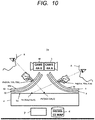
- FIG. 10 is a diagram illustrating a schematic configuration of an information input device according to Embodiment 2.
- the information input device 1a shown in FIG. 10 is an application of an embodiment or Embodiment 1.
- FIG. 10 differs from FIG. 1 in that the touch detection device 30, the protection film 40 including the touch surface 40a, and the detector 50 are provided in FIG. 10 .
- the information input device 1a shown in FIG. 10 includes a plurality of touch detection device 3 and 30 provided for one display device 2, and a plurality of detector (cameras A and B) 5 and 50 for detecting a plurality of operators, and enables, for example, a touch input from the operator A to the touch detection device 3 and a touch input from the operator B to the touch detection device 30.
- the storage device 6 stores a distance map including distance information d of a plurality of points between the touch surface 4a and the display surface 2a, and a distance map including distance information d of a plurality of points between the touch surface 40a and the display surface 2a.
- the detector (camera A) 5 is a unit for detecting the direction of the viewpoint of the operator A and the positions of the faces and eyes of the operator A.
- the detector (camera B) 50 is a unit for detecting the direction of the viewpoint of the operator B and the positions of the faces and eyes of the operator B.
- the corrector 7 performs coordinate correction on the touch coordinates Pa(X1a, Y1a, Z1a), Pb(X1b, Y1b, Z1b) detected by the touch detection device 3, 30 to the touch coordinates Pa' (X2a, Y2a, 0) and Pb' (X2b, Y2b, 0) based on the information of the viewpoints (positions of faces and eyes) of the operators A, B acquired by the detector 5, 50 and the distance information d of the touch surface 4a, 40a, and the display surface 2a from the storage device 6.
- the touch coordinates Pa (X1a, Y1a, Z1a) of the operator A's finger on the touch surface 4a are corrected to the touch coordinates Pa' (X2a, Y2a, 0) on the display surface 2a of the display device 2 in the same manner as in the embodiment or Embodiment 1.
- the touch coordinates Pb (X1b, Y1b, Z1b) of the operator B's finger on the touch surface 40a are corrected to the touch coordinates Pb' (X 2 b, Y 2 b, 0) on the display surface 2a of the display device 2.
- the rest of the configuration is the same as that of the embodiment or the Embodiment 1, and therefore the explanation thereof is omitted.
- FIG. 11 is a diagram illustrating an exemplary configuration of an information input device according to Embodiment 2.
- the information input device 1a shown in FIG. 11 differs from that shown in FIG. 1 in that, in FIG. 11 , a captured image of the detection device 50 is input to the image recognition unit 71, and the detection result of the touch detection device 30 is input to the coordinate corrector 73.
- the rest of the configuration is the same as that of FIG. 2 , and a description thereof will be omitted.
- the image recognition unit 71 also has a function of performing a recognition function for the captured image of the detector (camera B) 50 and extracting the coordinate information of the face and eyes of the operator B on the image.
- the viewpoint direction calculator 72 has a function of calculating the viewpoint direction of the operator A as an azimuth angle ( ⁇ ) and an elevation angle ( ⁇ ), and a function of calculating the viewpoint direction of the operator B as an azimuth angle ( ⁇ ) and an elevation angle ( ⁇ ).
- the coordinate corrector 73 has a function of correcting the touch coordinates Pa (X1a, Y1a, Z1a) of the finger of the operator A to the touch coordinates Pa' (X2a, Y2a, 0) on the display surface 2a of the display device 2, and also a function of correcting the touch coordinates Pb (X1b, Y1b, Z1b) of the finger of the operator B on the touch surface 40a to the touch coordinates Pb' (X2b, Y2b, 0) on the display surface 2a of the display device 2. Therefore, the plurality of detectors (cameras A and B) 5 and 50 serve as an identifying unit for identifying whether the input is an input of the operator A or an input of the operator B.
- the corrector 7 in FIG. 11 is shared by the touch detection device 3, the detector 5, the touch detection device 30, and the detector 50, the configuration of the corrector 7 is not limited to FIG. 11 .
- two correctors 7 may be provided, one corrector may be assigned to the touch detection device 3 and the detector 5, and the other corrector may be assigned to the touch detection device 30 and the detector 50.
- Embodiment 2 it is possible to provide an information input device in which a plurality of operators A and B can access a single display device (display surface 2a) without interfering with each other's operations, by inputting on a complicated touch surface and considering parallaxes.
- the system including the information input device of Embodiment 2 it is possible to realize the multi-touch control by identifying and grasping which of the operations of the operator A and the operator B is.
- the identification of the touch operation by a plurality of fingers can be performed by a multi-touch technique, there has been a problem that it is impossible to determine which touch is which touch.
- the touch surface can be separated and identified for each operator. Therefore, even if the touch operation is performed on the same display device, the system can provide desired services while the system grasps who the touch operation is performed.
- the corrector 7 performs coordinate correction of the touch coordinates Pa, Pb detected by the touch detection device 3, 30 to the touch coordinates Pa', Pb' based on the information of the viewpoints of the operators A, B acquired by the detector 5, 50 and the distance information d from the storage device 6.
- a touch operation with high accuracy can be realized.
- the possibility of causing a sense of discomfort or trouble in the operation can be reduced.
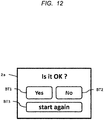
- FIG. 12 is a diagram illustrating an exemplary display of the display surface of the information input device according to Embodiment 3.
- Embodiment 1 and Embodiment 2 are configured on the assumption that the finger Af of the operator A touches the touch surface 4a, but the present invention is not limited thereto.
- a touch surface such as a motion control mounted on a car navigation device may be formed in a part of a normal space of the display surface. That is, the present Embodiment is applied to a non-contact type information input device which does not include a physical touch surface and realizes touch operations from positions of fingers in space by recognizing images of captured images from cameras.
- the spatial depth of the touch-down determination is changed in response to the content of the input request information displayed on the display surface 2a of the display device 2 by utilizing the distance map held in the storage device 6.
- the distance map is dynamically generated from the displayed content, thereby setting the spatial touch surface of the input request information which is likely to be operated by the operator A to a short distance from the operator A. As a result, the operability for the operator A can be improved.
- a spatial touch surface of the input request information that the operator A does not want to operate much or the input request information that the operator A does not need to operate is set to a long distance with respect to the operator A, thereby suppressing an erroneous operation.
- FIG. 12 shows display images on the display surface 2a of the display device 2.
- the display screen includes a character string for requesting a reply of "Is it OK?" and the first button BT1, the second button BT2, and the third button BT3 as the input request information.
- the first button BT1 includes a "yes” display
- the second button BT2 includes a "no” display
- the third button BT3 has a "start again” display.
- the button is an example, and may be a character string, a figure, or an icon.
- the priority of the use of the first button BT1 and the second button BT2 tends to be higher, and the priority of the use of the third button BT3 is considered to be lower than that of the first button BT1 and the second button BT2.
- the priority of use is high may be referred to as "the operator A wants to operate” and "the priority of use is low” may be referred to as "the operator A wants not to operate too much”.
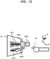
- FIG. 13 is a diagram illustrating a spatial touch surface in which the use priority is taken into consideration.
- FIG. 14 is a diagram illustrating a spatial touch surface when FIG. 13 is viewed from above.
- the spatial touch surface (first touch surface) TBT1 of the first button BT1 and the spatial touch surface TBT2 of the second button BT2 which are highly prioritized for use, exist in a space of the distance DT1 from the display surface 2a of the display device 2.
- the spatial touch surface (second touch surface) TBT3 of the third buttons BT3 with the lower usage priorities exists in the space of the distance DT2 from the display surface 2a of the display device 2.
- the distance DT2 is shorter than the distance DT1 (DT2 ⁇ DT1).
- the spatial touch surface TBT1 of the first button BT1 and the spatial touch surface TBT2 of the second button BT2 are arranged closer to the position of the finger Af of the operator A than the spatial touch surface TBT3 of the third button BT3. Therefore, the operator A is in a state in which the first button BT1 and the second button BT2 are easy to select, and the third button BT3 is difficult to select compared with the first button BT1 and the second button BT2.
- the detector (camera) 5 photographs the position of the finger Af of the operator A, and inputs the captured image to the image recognition unit 71.
- the image recognition unit 74 recognizes the coordinate of the position of the finger Af from the captured image, and inputs the finger Af to the touch detection device 3.
- the touch detection device 3 determines the first button BT1, the second button BT2, or the third button BT3 selected by the operator A based on the coordinate of the position of the finger Af from the captured image inputted from the image recognition unit 74, and the spatial touch surface TBT1, the TBT2, and the TBT3 distance information (DT1, DT2, and DT3) of the first button BT1, the second button BT2, and the third button BT3 currently displayed in the displayed image.
- the determination result is input to the display information generator 21.
- the display information generator 21 inputs the information of the first button BT1, the second button BT2, or the third button BT3 selected by the operator A to the system including the information input device 1b.
- Embodiment 3 is not limited to the car navigation device.
- the present invention is also applicable to a head-up display technology for displaying characters, graphics, and the like on a windshield of an automobile.
- the present invention can be used in a case where a vehicle to be followed is selected from a plurality of vehicles on shield glass in automatic driving or the like, or in a case where a trip meter is changed or reset.
Landscapes
- Engineering & Computer Science (AREA)
- General Engineering & Computer Science (AREA)
- Theoretical Computer Science (AREA)
- Human Computer Interaction (AREA)
- Physics & Mathematics (AREA)
- General Physics & Mathematics (AREA)
- Position Input By Displaying (AREA)
- User Interface Of Digital Computer (AREA)
Applications Claiming Priority (1)
| Application Number | Priority Date | Filing Date | Title |
|---|---|---|---|
| JP2018226226A JP7178888B2 (ja) | 2018-12-03 | 2018-12-03 | 情報入力装置 |
Publications (2)
| Publication Number | Publication Date |
|---|---|
| EP3663897A1 true EP3663897A1 (de) | 2020-06-10 |
| EP3663897B1 EP3663897B1 (de) | 2023-11-01 |
Family
ID=68581567
Family Applications (1)
| Application Number | Title | Priority Date | Filing Date |
|---|---|---|---|
| EP19209123.9A Active EP3663897B1 (de) | 2018-12-03 | 2019-11-14 | Informationseingabevorrichtung |
Country Status (4)
| Country | Link |
|---|---|
| US (2) | US20200174641A1 (de) |
| EP (1) | EP3663897B1 (de) |
| JP (1) | JP7178888B2 (de) |
| CN (2) | CN111258443B (de) |
Cited By (1)
| Publication number | Priority date | Publication date | Assignee | Title |
|---|---|---|---|---|
| EP4152128A1 (de) * | 2021-09-17 | 2023-03-22 | Bayerische Motoren Werke Aktiengesellschaft | Steuereinheit zur verbesserung der benutzerberührungssteuerung, verfahren und computerprogramm |
Families Citing this family (1)
| Publication number | Priority date | Publication date | Assignee | Title |
|---|---|---|---|---|
| JP2023131286A (ja) * | 2022-03-09 | 2023-09-22 | マクセル株式会社 | 入力装置およびエレベータシステム |
Citations (5)
| Publication number | Priority date | Publication date | Assignee | Title |
|---|---|---|---|---|
| JPH11296304A (ja) * | 1998-04-10 | 1999-10-29 | Ricoh Co Ltd | 画面表示入力装置及び視差補正方法 |
| EP2713244A1 (de) * | 2012-10-01 | 2014-04-02 | Alcatel Lucent | Berührungsbildschirmvorrichtung mit Parallaxenfehlerkompensierung |
| US20150153902A1 (en) * | 2013-03-18 | 2015-06-04 | Kabushiki Kaisha Toshiba | Information processing apparatus, control method and storage medium |
| JP2017199062A (ja) | 2016-04-25 | 2017-11-02 | 京セラドキュメントソリューションズ株式会社 | 操作入力装置、画像形成装置及び操作入力方法 |
| JP2018060404A (ja) | 2016-10-06 | 2018-04-12 | 株式会社ジャパンディスプレイ | 表示装置およびタッチ操作の補正方法 |
Family Cites Families (18)
| Publication number | Priority date | Publication date | Assignee | Title |
|---|---|---|---|---|
| JP2009110275A (ja) * | 2007-10-30 | 2009-05-21 | Sharp Corp | 表示入力装置及びその視差補正方法 |
| DE112010001445T5 (de) * | 2009-03-31 | 2012-10-25 | Mitsubishi Electric Corporation | Anzeigeeingabegerät |
| JP2011165141A (ja) * | 2010-02-15 | 2011-08-25 | Sharp Corp | 電子機器および電子機器の制御方法 |
| WO2011114590A1 (ja) * | 2010-03-16 | 2011-09-22 | シャープ株式会社 | 位置入力装置、位置入力システム、位置入力方法、位置入力プログラム及びコンピュータ読み取り可能な記録媒体 |
| US9164621B2 (en) * | 2010-03-18 | 2015-10-20 | Fujifilm Corporation | Stereoscopic display apparatus and stereoscopic shooting apparatus, dominant eye judging method and dominant eye judging program for use therein, and recording medium |
| US8884928B1 (en) * | 2012-01-26 | 2014-11-11 | Amazon Technologies, Inc. | Correcting for parallax in electronic displays |
| JP2014049023A (ja) * | 2012-09-03 | 2014-03-17 | Sharp Corp | 入力装置 |
| TWI483152B (zh) * | 2012-10-25 | 2015-05-01 | Acer Inc | 觸碰位置補償方法及裝置 |
| US9280234B1 (en) * | 2013-06-25 | 2016-03-08 | Amazon Technologies, Inc. | Input correction for touch screens |
| US20160196002A1 (en) * | 2013-09-04 | 2016-07-07 | Sharp Kabushiki Kaisha | Display device |
| DE102013217772A1 (de) * | 2013-09-05 | 2015-03-05 | Robert Bosch Gmbh | Daten- und/oder Kommunikationsgerät sowie Verfahren zu dessen Steuerung |
| JP2015114682A (ja) | 2013-12-09 | 2015-06-22 | 小島プレス工業株式会社 | タッチパネル装置 |
| KR102224478B1 (ko) * | 2014-04-15 | 2021-03-08 | 엘지전자 주식회사 | 터치 센서티브 플렉서블 디스플레이 디바이스 및 그 제어 방법 |
| CN104298412A (zh) * | 2014-11-10 | 2015-01-21 | 上海摩软通讯技术有限公司 | 移动终端及其触摸屏操作校准方法 |
| JP6611501B2 (ja) | 2015-07-17 | 2019-11-27 | キヤノン株式会社 | 情報処理装置、仮想オブジェクトの操作方法、コンピュータプログラム、及び記憶媒体 |
| US9778792B2 (en) * | 2015-11-12 | 2017-10-03 | Dell Products L.P. | Information handling system desktop surface display touch input compensation |
| JP2017134709A (ja) * | 2016-01-29 | 2017-08-03 | 富士通株式会社 | 電子機器、電子機器の制御プログラム及びその方法 |
| JP6583113B2 (ja) | 2016-04-15 | 2019-10-02 | 株式会社デンソー | 情報処理装置及び表示システム |
-
2018
- 2018-12-03 JP JP2018226226A patent/JP7178888B2/ja active Active
-
2019
- 2019-10-08 US US16/595,942 patent/US20200174641A1/en not_active Abandoned
- 2019-11-14 EP EP19209123.9A patent/EP3663897B1/de active Active
- 2019-11-21 CN CN201911147813.2A patent/CN111258443B/zh active Active
- 2019-11-21 CN CN202410628614.8A patent/CN118567511A/zh active Pending
-
2021
- 2021-02-17 US US17/177,961 patent/US11455061B2/en active Active
Patent Citations (5)
| Publication number | Priority date | Publication date | Assignee | Title |
|---|---|---|---|---|
| JPH11296304A (ja) * | 1998-04-10 | 1999-10-29 | Ricoh Co Ltd | 画面表示入力装置及び視差補正方法 |
| EP2713244A1 (de) * | 2012-10-01 | 2014-04-02 | Alcatel Lucent | Berührungsbildschirmvorrichtung mit Parallaxenfehlerkompensierung |
| US20150153902A1 (en) * | 2013-03-18 | 2015-06-04 | Kabushiki Kaisha Toshiba | Information processing apparatus, control method and storage medium |
| JP2017199062A (ja) | 2016-04-25 | 2017-11-02 | 京セラドキュメントソリューションズ株式会社 | 操作入力装置、画像形成装置及び操作入力方法 |
| JP2018060404A (ja) | 2016-10-06 | 2018-04-12 | 株式会社ジャパンディスプレイ | 表示装置およびタッチ操作の補正方法 |
Cited By (1)
| Publication number | Priority date | Publication date | Assignee | Title |
|---|---|---|---|---|
| EP4152128A1 (de) * | 2021-09-17 | 2023-03-22 | Bayerische Motoren Werke Aktiengesellschaft | Steuereinheit zur verbesserung der benutzerberührungssteuerung, verfahren und computerprogramm |
Also Published As
| Publication number | Publication date |
|---|---|
| EP3663897B1 (de) | 2023-11-01 |
| US20210165551A1 (en) | 2021-06-03 |
| JP7178888B2 (ja) | 2022-11-28 |
| CN111258443B (zh) | 2024-06-07 |
| JP2020091509A (ja) | 2020-06-11 |
| CN118567511A (zh) | 2024-08-30 |
| US20200174641A1 (en) | 2020-06-04 |
| US11455061B2 (en) | 2022-09-27 |
| CN111258443A (zh) | 2020-06-09 |
Similar Documents
| Publication | Publication Date | Title |
|---|---|---|
| US10466794B2 (en) | Gesture recognition areas and sub-areas for interaction with real and virtual objects within augmented reality | |
| US8890819B2 (en) | Display input device and vehicle-mounted information equipment | |
| US9001208B2 (en) | Imaging sensor based multi-dimensional remote controller with multiple input mode | |
| US9878667B2 (en) | In-vehicle display apparatus and program product | |
| US10168769B2 (en) | Input apparatus, input method, and program | |
| US10168773B2 (en) | Position locating method and apparatus | |
| US20180260032A1 (en) | Input device, input method, and program | |
| EP3425488B1 (de) | System und verfahren zur kalibrierung und vorhersage einer berührungsposition eines zeigers auf einer berührungsaktivierten einheit | |
| US11455061B2 (en) | Information input device including a touch surface and a display surface | |
| CN115220636A (zh) | 虚拟操作方法、装置、电子设备及可读存储介质 | |
| JP2016114963A (ja) | 入力操作検出装置、プロジェクタ装置、電子黒板装置、デジタルサイネージ装置、及びプロジェクタシステム | |
| KR20160072306A (ko) | 스마트 펜 기반의 콘텐츠 증강 방법 및 시스템 | |
| KR102518535B1 (ko) | 차량의 영상 처리 장치 및 방법 | |
| US11899834B2 (en) | Information processing device and method | |
| US9300908B2 (en) | Information processing apparatus and information processing method | |
| JP6208977B2 (ja) | 情報処理装置、通信端末およびデータ取得方法 | |
| JP2014049023A (ja) | 入力装置 | |
| US20240397194A1 (en) | Electronic device, display method, and program | |
| US20250306675A1 (en) | Method and apparatus for moving virtual object, electronic device, and storage medium | |
| EP3059664A1 (de) | Verfahren zur steuerung einer vorrichtung durch gesten und system zur steuerung einer vorrichtung durch gesten | |
| US20210074015A1 (en) | Distance measuring device and distance measuring method | |
| WO2025092464A1 (zh) | 交互控制方法、装置、电子设备和存储介质 | |
| US9116573B2 (en) | Virtual control device | |
| JP2018073146A (ja) | 入力補正システムおよび入力補正プログラム | |
| WO2022191276A1 (ja) | 操作入力装置、操作入力方法及びプログラム |
Legal Events
| Date | Code | Title | Description |
|---|---|---|---|
| PUAI | Public reference made under article 153(3) epc to a published international application that has entered the european phase |
Free format text: ORIGINAL CODE: 0009012 |
|
| STAA | Information on the status of an ep patent application or granted ep patent |
Free format text: STATUS: THE APPLICATION HAS BEEN PUBLISHED |
|
| AK | Designated contracting states |
Kind code of ref document: A1 Designated state(s): AL AT BE BG CH CY CZ DE DK EE ES FI FR GB GR HR HU IE IS IT LI LT LU LV MC MK MT NL NO PL PT RO RS SE SI SK SM TR |
|
| AX | Request for extension of the european patent |
Extension state: BA ME |
|
| STAA | Information on the status of an ep patent application or granted ep patent |
Free format text: STATUS: REQUEST FOR EXAMINATION WAS MADE |
|
| 17P | Request for examination filed |
Effective date: 20201210 |
|
| RBV | Designated contracting states (corrected) |
Designated state(s): AL AT BE BG CH CY CZ DE DK EE ES FI FR GB GR HR HU IE IS IT LI LT LU LV MC MK MT NL NO PL PT RO RS SE SI SK SM TR |
|
| STAA | Information on the status of an ep patent application or granted ep patent |
Free format text: STATUS: EXAMINATION IS IN PROGRESS |
|
| 17Q | First examination report despatched |
Effective date: 20220221 |
|
| GRAP | Despatch of communication of intention to grant a patent |
Free format text: ORIGINAL CODE: EPIDOSNIGR1 |
|
| STAA | Information on the status of an ep patent application or granted ep patent |
Free format text: STATUS: GRANT OF PATENT IS INTENDED |
|
| INTG | Intention to grant announced |
Effective date: 20230428 |
|
| GRAS | Grant fee paid |
Free format text: ORIGINAL CODE: EPIDOSNIGR3 |
|
| GRAJ | Information related to disapproval of communication of intention to grant by the applicant or resumption of examination proceedings by the epo deleted |
Free format text: ORIGINAL CODE: EPIDOSDIGR1 |
|
| GRAL | Information related to payment of fee for publishing/printing deleted |
Free format text: ORIGINAL CODE: EPIDOSDIGR3 |
|
| STAA | Information on the status of an ep patent application or granted ep patent |
Free format text: STATUS: EXAMINATION IS IN PROGRESS |
|
| GRAP | Despatch of communication of intention to grant a patent |
Free format text: ORIGINAL CODE: EPIDOSNIGR1 |
|
| STAA | Information on the status of an ep patent application or granted ep patent |
Free format text: STATUS: GRANT OF PATENT IS INTENDED |
|
| GRAA | (expected) grant |
Free format text: ORIGINAL CODE: 0009210 |
|
| STAA | Information on the status of an ep patent application or granted ep patent |
Free format text: STATUS: THE PATENT HAS BEEN GRANTED |
|
| INTC | Intention to grant announced (deleted) | ||
| INTG | Intention to grant announced |
Effective date: 20230919 |
|
| AK | Designated contracting states |
Kind code of ref document: B1 Designated state(s): AL AT BE BG CH CY CZ DE DK EE ES FI FR GB GR HR HU IE IS IT LI LT LU LV MC MK MT NL NO PL PT RO RS SE SI SK SM TR |
|
| REG | Reference to a national code |
Ref country code: GB Ref legal event code: FG4D |
|
| REG | Reference to a national code |
Ref country code: CH Ref legal event code: EP |
|
| REG | Reference to a national code |
Ref country code: IE Ref legal event code: FG4D |
|
| REG | Reference to a national code |
Ref country code: DE Ref legal event code: R096 Ref document number: 602019040485 Country of ref document: DE |
|
| REG | Reference to a national code |
Ref country code: LT Ref legal event code: MG9D |
|
| REG | Reference to a national code |
Ref country code: NL Ref legal event code: MP Effective date: 20231101 |
|
| PG25 | Lapsed in a contracting state [announced via postgrant information from national office to epo] |
Ref country code: GR Free format text: LAPSE BECAUSE OF FAILURE TO SUBMIT A TRANSLATION OF THE DESCRIPTION OR TO PAY THE FEE WITHIN THE PRESCRIBED TIME-LIMIT Effective date: 20240202 |
|
| PG25 | Lapsed in a contracting state [announced via postgrant information from national office to epo] |
Ref country code: IS Free format text: LAPSE BECAUSE OF FAILURE TO SUBMIT A TRANSLATION OF THE DESCRIPTION OR TO PAY THE FEE WITHIN THE PRESCRIBED TIME-LIMIT Effective date: 20240301 |
|
| PG25 | Lapsed in a contracting state [announced via postgrant information from national office to epo] |
Ref country code: LT Free format text: LAPSE BECAUSE OF FAILURE TO SUBMIT A TRANSLATION OF THE DESCRIPTION OR TO PAY THE FEE WITHIN THE PRESCRIBED TIME-LIMIT Effective date: 20231101 |
|
| REG | Reference to a national code |
Ref country code: AT Ref legal event code: MK05 Ref document number: 1627957 Country of ref document: AT Kind code of ref document: T Effective date: 20231101 |
|
| PG25 | Lapsed in a contracting state [announced via postgrant information from national office to epo] |
Ref country code: NL Free format text: LAPSE BECAUSE OF FAILURE TO SUBMIT A TRANSLATION OF THE DESCRIPTION OR TO PAY THE FEE WITHIN THE PRESCRIBED TIME-LIMIT Effective date: 20231101 |
|
| PG25 | Lapsed in a contracting state [announced via postgrant information from national office to epo] |
Ref country code: AT Free format text: LAPSE BECAUSE OF FAILURE TO SUBMIT A TRANSLATION OF THE DESCRIPTION OR TO PAY THE FEE WITHIN THE PRESCRIBED TIME-LIMIT Effective date: 20231101 |
|
| PG25 | Lapsed in a contracting state [announced via postgrant information from national office to epo] |
Ref country code: ES Free format text: LAPSE BECAUSE OF FAILURE TO SUBMIT A TRANSLATION OF THE DESCRIPTION OR TO PAY THE FEE WITHIN THE PRESCRIBED TIME-LIMIT Effective date: 20231101 |
|
| PG25 | Lapsed in a contracting state [announced via postgrant information from national office to epo] |
Ref country code: NL Free format text: LAPSE BECAUSE OF FAILURE TO SUBMIT A TRANSLATION OF THE DESCRIPTION OR TO PAY THE FEE WITHIN THE PRESCRIBED TIME-LIMIT Effective date: 20231101 Ref country code: LT Free format text: LAPSE BECAUSE OF FAILURE TO SUBMIT A TRANSLATION OF THE DESCRIPTION OR TO PAY THE FEE WITHIN THE PRESCRIBED TIME-LIMIT Effective date: 20231101 Ref country code: IS Free format text: LAPSE BECAUSE OF FAILURE TO SUBMIT A TRANSLATION OF THE DESCRIPTION OR TO PAY THE FEE WITHIN THE PRESCRIBED TIME-LIMIT Effective date: 20240301 Ref country code: GR Free format text: LAPSE BECAUSE OF FAILURE TO SUBMIT A TRANSLATION OF THE DESCRIPTION OR TO PAY THE FEE WITHIN THE PRESCRIBED TIME-LIMIT Effective date: 20240202 Ref country code: ES Free format text: LAPSE BECAUSE OF FAILURE TO SUBMIT A TRANSLATION OF THE DESCRIPTION OR TO PAY THE FEE WITHIN THE PRESCRIBED TIME-LIMIT Effective date: 20231101 Ref country code: BG Free format text: LAPSE BECAUSE OF FAILURE TO SUBMIT A TRANSLATION OF THE DESCRIPTION OR TO PAY THE FEE WITHIN THE PRESCRIBED TIME-LIMIT Effective date: 20240201 Ref country code: AT Free format text: LAPSE BECAUSE OF FAILURE TO SUBMIT A TRANSLATION OF THE DESCRIPTION OR TO PAY THE FEE WITHIN THE PRESCRIBED TIME-LIMIT Effective date: 20231101 Ref country code: PT Free format text: LAPSE BECAUSE OF FAILURE TO SUBMIT A TRANSLATION OF THE DESCRIPTION OR TO PAY THE FEE WITHIN THE PRESCRIBED TIME-LIMIT Effective date: 20240301 |
|
| PG25 | Lapsed in a contracting state [announced via postgrant information from national office to epo] |
Ref country code: SE Free format text: LAPSE BECAUSE OF FAILURE TO SUBMIT A TRANSLATION OF THE DESCRIPTION OR TO PAY THE FEE WITHIN THE PRESCRIBED TIME-LIMIT Effective date: 20231101 Ref country code: RS Free format text: LAPSE BECAUSE OF FAILURE TO SUBMIT A TRANSLATION OF THE DESCRIPTION OR TO PAY THE FEE WITHIN THE PRESCRIBED TIME-LIMIT Effective date: 20231101 Ref country code: PL Free format text: LAPSE BECAUSE OF FAILURE TO SUBMIT A TRANSLATION OF THE DESCRIPTION OR TO PAY THE FEE WITHIN THE PRESCRIBED TIME-LIMIT Effective date: 20231101 Ref country code: NO Free format text: LAPSE BECAUSE OF FAILURE TO SUBMIT A TRANSLATION OF THE DESCRIPTION OR TO PAY THE FEE WITHIN THE PRESCRIBED TIME-LIMIT Effective date: 20240201 Ref country code: LV Free format text: LAPSE BECAUSE OF FAILURE TO SUBMIT A TRANSLATION OF THE DESCRIPTION OR TO PAY THE FEE WITHIN THE PRESCRIBED TIME-LIMIT Effective date: 20231101 Ref country code: HR Free format text: LAPSE BECAUSE OF FAILURE TO SUBMIT A TRANSLATION OF THE DESCRIPTION OR TO PAY THE FEE WITHIN THE PRESCRIBED TIME-LIMIT Effective date: 20231101 |
|
| REG | Reference to a national code |
Ref country code: CH Ref legal event code: PL |
|
| PG25 | Lapsed in a contracting state [announced via postgrant information from national office to epo] |
Ref country code: DK Free format text: LAPSE BECAUSE OF FAILURE TO SUBMIT A TRANSLATION OF THE DESCRIPTION OR TO PAY THE FEE WITHIN THE PRESCRIBED TIME-LIMIT Effective date: 20231101 |
|
| PG25 | Lapsed in a contracting state [announced via postgrant information from national office to epo] |
Ref country code: LU Free format text: LAPSE BECAUSE OF NON-PAYMENT OF DUE FEES Effective date: 20231114 |
|
| PG25 | Lapsed in a contracting state [announced via postgrant information from national office to epo] |
Ref country code: CH Free format text: LAPSE BECAUSE OF NON-PAYMENT OF DUE FEES Effective date: 20231130 |
|
| PG25 | Lapsed in a contracting state [announced via postgrant information from national office to epo] |
Ref country code: CZ Free format text: LAPSE BECAUSE OF FAILURE TO SUBMIT A TRANSLATION OF THE DESCRIPTION OR TO PAY THE FEE WITHIN THE PRESCRIBED TIME-LIMIT Effective date: 20231101 |
|
| PG25 | Lapsed in a contracting state [announced via postgrant information from national office to epo] |
Ref country code: SK Free format text: LAPSE BECAUSE OF FAILURE TO SUBMIT A TRANSLATION OF THE DESCRIPTION OR TO PAY THE FEE WITHIN THE PRESCRIBED TIME-LIMIT Effective date: 20231101 |
|
| PG25 | Lapsed in a contracting state [announced via postgrant information from national office to epo] |
Ref country code: SM Free format text: LAPSE BECAUSE OF FAILURE TO SUBMIT A TRANSLATION OF THE DESCRIPTION OR TO PAY THE FEE WITHIN THE PRESCRIBED TIME-LIMIT Effective date: 20231101 Ref country code: SK Free format text: LAPSE BECAUSE OF FAILURE TO SUBMIT A TRANSLATION OF THE DESCRIPTION OR TO PAY THE FEE WITHIN THE PRESCRIBED TIME-LIMIT Effective date: 20231101 Ref country code: LU Free format text: LAPSE BECAUSE OF NON-PAYMENT OF DUE FEES Effective date: 20231114 Ref country code: IT Free format text: LAPSE BECAUSE OF FAILURE TO SUBMIT A TRANSLATION OF THE DESCRIPTION OR TO PAY THE FEE WITHIN THE PRESCRIBED TIME-LIMIT Effective date: 20231101 Ref country code: EE Free format text: LAPSE BECAUSE OF FAILURE TO SUBMIT A TRANSLATION OF THE DESCRIPTION OR TO PAY THE FEE WITHIN THE PRESCRIBED TIME-LIMIT Effective date: 20231101 Ref country code: DK Free format text: LAPSE BECAUSE OF FAILURE TO SUBMIT A TRANSLATION OF THE DESCRIPTION OR TO PAY THE FEE WITHIN THE PRESCRIBED TIME-LIMIT Effective date: 20231101 Ref country code: CZ Free format text: LAPSE BECAUSE OF FAILURE TO SUBMIT A TRANSLATION OF THE DESCRIPTION OR TO PAY THE FEE WITHIN THE PRESCRIBED TIME-LIMIT Effective date: 20231101 Ref country code: CH Free format text: LAPSE BECAUSE OF NON-PAYMENT OF DUE FEES Effective date: 20231130 |
|
| REG | Reference to a national code |
Ref country code: BE Ref legal event code: MM Effective date: 20231130 |
|
| REG | Reference to a national code |
Ref country code: DE Ref legal event code: R097 Ref document number: 602019040485 Country of ref document: DE |
|
| PG25 | Lapsed in a contracting state [announced via postgrant information from national office to epo] |
Ref country code: MC Free format text: LAPSE BECAUSE OF FAILURE TO SUBMIT A TRANSLATION OF THE DESCRIPTION OR TO PAY THE FEE WITHIN THE PRESCRIBED TIME-LIMIT Effective date: 20231101 |
|
| PG25 | Lapsed in a contracting state [announced via postgrant information from national office to epo] |
Ref country code: MC Free format text: LAPSE BECAUSE OF FAILURE TO SUBMIT A TRANSLATION OF THE DESCRIPTION OR TO PAY THE FEE WITHIN THE PRESCRIBED TIME-LIMIT Effective date: 20231101 |
|
| PLBE | No opposition filed within time limit |
Free format text: ORIGINAL CODE: 0009261 |
|
| STAA | Information on the status of an ep patent application or granted ep patent |
Free format text: STATUS: NO OPPOSITION FILED WITHIN TIME LIMIT |
|
| REG | Reference to a national code |
Ref country code: IE Ref legal event code: MM4A |
|
| 26N | No opposition filed |
Effective date: 20240802 |
|
| PG25 | Lapsed in a contracting state [announced via postgrant information from national office to epo] |
Ref country code: IE Free format text: LAPSE BECAUSE OF NON-PAYMENT OF DUE FEES Effective date: 20231114 |
|
| PG25 | Lapsed in a contracting state [announced via postgrant information from national office to epo] |
Ref country code: BE Free format text: LAPSE BECAUSE OF NON-PAYMENT OF DUE FEES Effective date: 20231130 |
|
| PG25 | Lapsed in a contracting state [announced via postgrant information from national office to epo] |
Ref country code: FR Free format text: LAPSE BECAUSE OF NON-PAYMENT OF DUE FEES Effective date: 20240101 |
|
| GBPC | Gb: european patent ceased through non-payment of renewal fee |
Effective date: 20240201 |
|
| PG25 | Lapsed in a contracting state [announced via postgrant information from national office to epo] |
Ref country code: SI Free format text: LAPSE BECAUSE OF FAILURE TO SUBMIT A TRANSLATION OF THE DESCRIPTION OR TO PAY THE FEE WITHIN THE PRESCRIBED TIME-LIMIT Effective date: 20231101 |
|
| PG25 | Lapsed in a contracting state [announced via postgrant information from national office to epo] |
Ref country code: SI Free format text: LAPSE BECAUSE OF FAILURE TO SUBMIT A TRANSLATION OF THE DESCRIPTION OR TO PAY THE FEE WITHIN THE PRESCRIBED TIME-LIMIT Effective date: 20231101 Ref country code: IE Free format text: LAPSE BECAUSE OF NON-PAYMENT OF DUE FEES Effective date: 20231114 Ref country code: FR Free format text: LAPSE BECAUSE OF NON-PAYMENT OF DUE FEES Effective date: 20240101 Ref country code: BE Free format text: LAPSE BECAUSE OF NON-PAYMENT OF DUE FEES Effective date: 20231130 |
|
| PG25 | Lapsed in a contracting state [announced via postgrant information from national office to epo] |
Ref country code: GB Free format text: LAPSE BECAUSE OF NON-PAYMENT OF DUE FEES Effective date: 20240201 |
|
| PG25 | Lapsed in a contracting state [announced via postgrant information from national office to epo] |
Ref country code: GB Free format text: LAPSE BECAUSE OF NON-PAYMENT OF DUE FEES Effective date: 20240201 |
|
| PG25 | Lapsed in a contracting state [announced via postgrant information from national office to epo] |
Ref country code: RO Free format text: LAPSE BECAUSE OF FAILURE TO SUBMIT A TRANSLATION OF THE DESCRIPTION OR TO PAY THE FEE WITHIN THE PRESCRIBED TIME-LIMIT Effective date: 20231101 |
|
| PG25 | Lapsed in a contracting state [announced via postgrant information from national office to epo] |
Ref country code: FI Free format text: LAPSE BECAUSE OF FAILURE TO SUBMIT A TRANSLATION OF THE DESCRIPTION OR TO PAY THE FEE WITHIN THE PRESCRIBED TIME-LIMIT Effective date: 20231101 |
|
| PG25 | Lapsed in a contracting state [announced via postgrant information from national office to epo] |
Ref country code: CY Free format text: LAPSE BECAUSE OF FAILURE TO SUBMIT A TRANSLATION OF THE DESCRIPTION OR TO PAY THE FEE WITHIN THE PRESCRIBED TIME-LIMIT; INVALID AB INITIO Effective date: 20191114 |
|
| PG25 | Lapsed in a contracting state [announced via postgrant information from national office to epo] |
Ref country code: HU Free format text: LAPSE BECAUSE OF FAILURE TO SUBMIT A TRANSLATION OF THE DESCRIPTION OR TO PAY THE FEE WITHIN THE PRESCRIBED TIME-LIMIT; INVALID AB INITIO Effective date: 20191114 |
|
| PG25 | Lapsed in a contracting state [announced via postgrant information from national office to epo] |
Ref country code: TR Free format text: LAPSE BECAUSE OF FAILURE TO SUBMIT A TRANSLATION OF THE DESCRIPTION OR TO PAY THE FEE WITHIN THE PRESCRIBED TIME-LIMIT Effective date: 20231101 |
|
| PGFP | Annual fee paid to national office [announced via postgrant information from national office to epo] |
Ref country code: DE Payment date: 20251126 Year of fee payment: 7 |