EP3663836B1 - Laserkombinierervorrichtung - Google Patents
Laserkombinierervorrichtung Download PDFInfo
- Publication number
- EP3663836B1 EP3663836B1 EP18841611.9A EP18841611A EP3663836B1 EP 3663836 B1 EP3663836 B1 EP 3663836B1 EP 18841611 A EP18841611 A EP 18841611A EP 3663836 B1 EP3663836 B1 EP 3663836B1
- Authority
- EP
- European Patent Office
- Prior art keywords
- laser beam
- optical element
- laser beams
- diffractive optical
- circular laser
- Prior art date
- Legal status (The legal status is an assumption and is not a legal conclusion. Google has not performed a legal analysis and makes no representation as to the accuracy of the status listed.)
- Active
Links
Images




Classifications
-
- B—PERFORMING OPERATIONS; TRANSPORTING
- B23—MACHINE TOOLS; METAL-WORKING NOT OTHERWISE PROVIDED FOR
- B23K—SOLDERING OR UNSOLDERING; WELDING; CLADDING OR PLATING BY SOLDERING OR WELDING; CUTTING BY APPLYING HEAT LOCALLY, e.g. FLAME CUTTING; WORKING BY LASER BEAM
- B23K26/00—Working by laser beam, e.g. welding, cutting or boring
- B23K26/02—Positioning or observing the workpiece, e.g. with respect to the point of impact; Aligning, aiming or focusing the laser beam
- B23K26/06—Shaping the laser beam, e.g. by masks or multi-focusing
- B23K26/0604—Shaping the laser beam, e.g. by masks or multi-focusing by a combination of beams
- B23K26/0608—Shaping the laser beam, e.g. by masks or multi-focusing by a combination of beams in the same heat affected zone [HAZ]
-
- G—PHYSICS
- G02—OPTICS
- G02B—OPTICAL ELEMENTS, SYSTEMS OR APPARATUS
- G02B27/00—Optical systems or apparatus not provided for by any of the groups G02B1/00 - G02B26/00, G02B30/00
- G02B27/10—Beam splitting or combining systems
- G02B27/1006—Beam splitting or combining systems for splitting or combining different wavelengths
-
- B—PERFORMING OPERATIONS; TRANSPORTING
- B23—MACHINE TOOLS; METAL-WORKING NOT OTHERWISE PROVIDED FOR
- B23K—SOLDERING OR UNSOLDERING; WELDING; CLADDING OR PLATING BY SOLDERING OR WELDING; CUTTING BY APPLYING HEAT LOCALLY, e.g. FLAME CUTTING; WORKING BY LASER BEAM
- B23K26/00—Working by laser beam, e.g. welding, cutting or boring
- B23K26/02—Positioning or observing the workpiece, e.g. with respect to the point of impact; Aligning, aiming or focusing the laser beam
- B23K26/06—Shaping the laser beam, e.g. by masks or multi-focusing
- B23K26/064—Shaping the laser beam, e.g. by masks or multi-focusing by means of optical elements, e.g. lenses, mirrors or prisms
-
- G—PHYSICS
- G02—OPTICS
- G02B—OPTICAL ELEMENTS, SYSTEMS OR APPARATUS
- G02B13/00—Optical objectives specially designed for the purposes specified below
-
- G—PHYSICS
- G02—OPTICS
- G02B—OPTICAL ELEMENTS, SYSTEMS OR APPARATUS
- G02B13/00—Optical objectives specially designed for the purposes specified below
- G02B13/18—Optical objectives specially designed for the purposes specified below with lenses having one or more non-spherical faces, e.g. for reducing geometrical aberration
-
- G—PHYSICS
- G02—OPTICS
- G02B—OPTICAL ELEMENTS, SYSTEMS OR APPARATUS
- G02B19/00—Condensers, e.g. light collectors or similar non-imaging optics
- G02B19/0004—Condensers, e.g. light collectors or similar non-imaging optics characterised by the optical means employed
- G02B19/0009—Condensers, e.g. light collectors or similar non-imaging optics characterised by the optical means employed having refractive surfaces only
-
- G—PHYSICS
- G02—OPTICS
- G02B—OPTICAL ELEMENTS, SYSTEMS OR APPARATUS
- G02B19/00—Condensers, e.g. light collectors or similar non-imaging optics
- G02B19/0033—Condensers, e.g. light collectors or similar non-imaging optics characterised by the use
- G02B19/0047—Condensers, e.g. light collectors or similar non-imaging optics characterised by the use for use with a light source
- G02B19/0052—Condensers, e.g. light collectors or similar non-imaging optics characterised by the use for use with a light source the light source comprising a laser diode
- G02B19/0057—Condensers, e.g. light collectors or similar non-imaging optics characterised by the use for use with a light source the light source comprising a laser diode in the form of a laser diode array, e.g. laser diode bar
-
- G—PHYSICS
- G02—OPTICS
- G02B—OPTICAL ELEMENTS, SYSTEMS OR APPARATUS
- G02B27/00—Optical systems or apparatus not provided for by any of the groups G02B1/00 - G02B26/00, G02B30/00
- G02B27/09—Beam shaping, e.g. changing the cross-sectional area, not otherwise provided for
- G02B27/0905—Dividing and/or superposing multiple light beams
-
- G—PHYSICS
- G02—OPTICS
- G02B—OPTICAL ELEMENTS, SYSTEMS OR APPARATUS
- G02B27/00—Optical systems or apparatus not provided for by any of the groups G02B1/00 - G02B26/00, G02B30/00
- G02B27/10—Beam splitting or combining systems
-
- G—PHYSICS
- G02—OPTICS
- G02B—OPTICAL ELEMENTS, SYSTEMS OR APPARATUS
- G02B27/00—Optical systems or apparatus not provided for by any of the groups G02B1/00 - G02B26/00, G02B30/00
- G02B27/10—Beam splitting or combining systems
- G02B27/1086—Beam splitting or combining systems operating by diffraction only
-
- G—PHYSICS
- G02—OPTICS
- G02B—OPTICAL ELEMENTS, SYSTEMS OR APPARATUS
- G02B27/00—Optical systems or apparatus not provided for by any of the groups G02B1/00 - G02B26/00, G02B30/00
- G02B27/10—Beam splitting or combining systems
- G02B27/14—Beam splitting or combining systems operating by reflection only
-
- G—PHYSICS
- G02—OPTICS
- G02B—OPTICAL ELEMENTS, SYSTEMS OR APPARATUS
- G02B27/00—Optical systems or apparatus not provided for by any of the groups G02B1/00 - G02B26/00, G02B30/00
- G02B27/10—Beam splitting or combining systems
- G02B27/14—Beam splitting or combining systems operating by reflection only
- G02B27/141—Beam splitting or combining systems operating by reflection only using dichroic mirrors
-
- G—PHYSICS
- G02—OPTICS
- G02B—OPTICAL ELEMENTS, SYSTEMS OR APPARATUS
- G02B27/00—Optical systems or apparatus not provided for by any of the groups G02B1/00 - G02B26/00, G02B30/00
- G02B27/10—Beam splitting or combining systems
- G02B27/14—Beam splitting or combining systems operating by reflection only
- G02B27/145—Beam splitting or combining systems operating by reflection only having sequential partially reflecting surfaces
-
- G—PHYSICS
- G02—OPTICS
- G02B—OPTICAL ELEMENTS, SYSTEMS OR APPARATUS
- G02B27/00—Optical systems or apparatus not provided for by any of the groups G02B1/00 - G02B26/00, G02B30/00
- G02B27/40—Optical focusing aids
-
- G—PHYSICS
- G02—OPTICS
- G02B—OPTICAL ELEMENTS, SYSTEMS OR APPARATUS
- G02B27/00—Optical systems or apparatus not provided for by any of the groups G02B1/00 - G02B26/00, G02B30/00
- G02B27/42—Diffraction optics, i.e. systems including a diffractive element being designed for providing a diffractive effect
-
- G—PHYSICS
- G02—OPTICS
- G02B—OPTICAL ELEMENTS, SYSTEMS OR APPARATUS
- G02B5/00—Optical elements other than lenses
- G02B5/001—Axicons, waxicons, reflaxicons
-
- G—PHYSICS
- G02—OPTICS
- G02B—OPTICAL ELEMENTS, SYSTEMS OR APPARATUS
- G02B5/00—Optical elements other than lenses
- G02B5/08—Mirrors
- G02B5/10—Mirrors with curved faces
-
- G—PHYSICS
- G02—OPTICS
- G02B—OPTICAL ELEMENTS, SYSTEMS OR APPARATUS
- G02B5/00—Optical elements other than lenses
- G02B5/18—Diffraction gratings
-
- G—PHYSICS
- G02—OPTICS
- G02B—OPTICAL ELEMENTS, SYSTEMS OR APPARATUS
- G02B5/00—Optical elements other than lenses
- G02B5/18—Diffraction gratings
- G02B5/1861—Reflection gratings characterised by their structure, e.g. step profile, contours of substrate or grooves, pitch variations, materials
-
- G—PHYSICS
- G02—OPTICS
- G02B—OPTICAL ELEMENTS, SYSTEMS OR APPARATUS
- G02B5/00—Optical elements other than lenses
- G02B5/18—Diffraction gratings
- G02B5/1866—Transmission gratings characterised by their structure, e.g. step profile, contours of substrate or grooves, pitch variations, materials
-
- H—ELECTRICITY
- H01—ELECTRIC ELEMENTS
- H01S—DEVICES USING THE PROCESS OF LIGHT AMPLIFICATION BY STIMULATED EMISSION OF RADIATION [LASER] TO AMPLIFY OR GENERATE LIGHT; DEVICES USING STIMULATED EMISSION OF ELECTROMAGNETIC RADIATION IN WAVE RANGES OTHER THAN OPTICAL
- H01S5/00—Semiconductor lasers
- H01S5/40—Arrangement of two or more semiconductor lasers, not provided for in groups H01S5/02 - H01S5/30
- H01S5/4012—Beam combining, e.g. by the use of fibres, gratings, polarisers, prisms
-
- G—PHYSICS
- G02—OPTICS
- G02B—OPTICAL ELEMENTS, SYSTEMS OR APPARATUS
- G02B27/00—Optical systems or apparatus not provided for by any of the groups G02B1/00 - G02B26/00, G02B30/00
- G02B27/0025—Optical systems or apparatus not provided for by any of the groups G02B1/00 - G02B26/00, G02B30/00 for optical correction, e.g. distorsion, aberration
- G02B27/005—Optical systems or apparatus not provided for by any of the groups G02B1/00 - G02B26/00, G02B30/00 for optical correction, e.g. distorsion, aberration for correction of secondary colour or higher-order chromatic aberrations
- G02B27/0056—Optical systems or apparatus not provided for by any of the groups G02B1/00 - G02B26/00, G02B30/00 for optical correction, e.g. distorsion, aberration for correction of secondary colour or higher-order chromatic aberrations by using a diffractive optical element
Definitions
- the present invention relates to a laser beam combining device, and particularly to a laser beam combining device that combines a plurality of circular laser beams.
- a device that combines a plurality of circular laser beams for example, is a laser beam combining device disclosed in PTL 1.
- a shaping optical unit concentrically emits a plurality of circular laser beams having mutually different increments in outer diameter dimensions per unit propagation distance. Then, these circular laser beams are reflected by a secondary mirror of a condensing optical system, overlapped by a primary mirror, and then condensed.
- a radius of curvature of the secondary mirror is set, such that focal positions of the plurality of circular laser beams are close to each other. This can reduce an area of irradiation of the plurality of circular laser beams, and the irradiation with a high power density is achieved.
- this requires the circular laser beams to be shifted from each other on an emission surface of a condensing optical system. That is, when the circular laser beams are completely overlapped with each other on the emission surface of the condensing optical system, the focal positions of the circular laser beams do not completely coincide with each other.
- EP 3 064 986 A1 discloses a laser beam combining device according to the preamble of claim 1.
- JP 2016 112609 A discloses a similar device in which the optical element which is responsible for the divergence compensation is not a diffractive optical element.
- US 2007/098324 A1 shows an optical multiplexer.
- Documents EP 0 137 976 A2 and JP H10 134401 A show diffractive elements comprising annular regions.
- a laser beam combining device includes an emission optical system that emits a plurality of circular laser beams propagated coaxially and having mutually different wavelengths, and a diffractive optical element that is concentric and diffracts the plurality of circular laser beams, in which the diffractive optical element diffracts the plurality of circular laser beams in accordance with the wavelengths of the circular laser beams, such that local diffraction angles of diffracted light of the plurality of circular laser beams incident at mutually different local incidence angles are equal to each other.
- the diffractive optical element may be disposed at a position in which the plurality of circular laser beams overlaps each other.
- the irradiation power density of the synthetic laser beam obtained by combining the diffracted light can be enhanced by overlapping the diffracted light of the plurality of circular laser beams with each other.
- the diffractive optical element may have an incidence surface or an emission surface on which a plurality of annular regions that is concentric and divided by a plurality of steps is formed.
- the plurality of annular regions is formed on the incidence surface of the diffractive optical element, the local diffraction angles of the diffracted light of the circular laser beam reflected and diffracted by the incidence surface can be matched.
- the plurality of annular regions is formed on the emission surface of the diffractive optical element, the local diffraction angles of the diffracted light of the circular laser beam that is transmitted and diffracted by the emission surface can be matched.
- ⁇ n each of the wavelengths of the plurality of circular laser beams
- ⁇ n a local incidence angle of the plurality of circular laser beams to the diffractive optical element
- d represents a distance dimension of each of the plurality of annular regions of the diffractive optical element
- ⁇ bl represents a blaze angle that is an inclination of each of the annular regions
- m represents a diffraction order
- N represents a number of the circular laser beams emitted from the emission optical system
- the plurality of circular laser beams can be diffracted in accordance with the wavelengths of the plurality of circular laser beam, such that the local diffraction angles of the diffracted light of the plurality of circular laser beams incident at mutually different local incidence angles are equal to each other.
- the laser beam combining device may further include a condensing optical system that condenses the diffracted light of the plurality of circular laser beams, and a magnifying optical system that magnifies the diffracted light of the plurality of circular laser beams between the diffractive optical element and the condensing optical system.
- a condensing optical system that condenses the diffracted light of the plurality of circular laser beams
- a magnifying optical system that magnifies the diffracted light of the plurality of circular laser beams between the diffractive optical element and the condensing optical system.
- the present invention has an effect that it can provide a laser beam combining device having the above-described configurations and an enhanced irradiation power density of a synthetic laser beam.
- the laser beam combining device 10 is a device that combines a plurality of circular laser beams IL into one synthetic laser beam CL.
- the laser beam combining device 10 includes an emission optical system 20, a diffractive optical element 30, a magnifying optical system 40, and a condensing optical system 50.
- the emission optical system 20 is an optical system that emits the plurality of circular laser beams IL coaxially propagated and having mutually different wavelengths, the emission optical system including a plurality of laser light sources 21 and a plurality of shaping optical units (hereinafter referred to as "units 22").
- the laser light source 21 is a laser device that emits a solid laser beam having a circular cross section, and a semiconductor laser, a fiber laser, a solid laser, or the like is used according to necessary characteristics.
- the plurality of (for example, three) laser light sources 21 (a first laser light source 21a, a second laser light source 21b, and a third laser light source 21c) is disposed, such that optical axes of the emitted solid laser beams are parallel to each other.
- the three solid laser beams have mutually different wavelengths.
- the third laser light source 21c, the second laser light source 21b, and the first laser light source 21a are arranged in that order from the side near the diffractive optical element 30.
- the unit 22 emits the circular laser beams IL having mutually different decrements in outer diameter dimensions per unit propagation distance.
- the plurality of (for example, three) units 22 (a first unit 22a, a second unit 22b, and a third unit 22c) is disposed corresponding to the laser light sources 21 (the first laser light source 21a, the second laser light source 21b, and the third laser light source 21c).
- the three units 22 are arranged in an order of the third unit 22c, the second unit 22b, and the first unit 22a from the side near the diffractive optical element 30.
- the circular laser beam IL is a ring-shaped laser beam from which a central portion of the laser beam having a circular cross section is removed.
- the unit 22 includes a pair of axicon mirrors 23 and 24 and a scraper mirror 25.
- the pair of axicon mirrors 23 and 24 includes a concave axicon mirror 23 and a convex axicon mirror 24, and the concave axicon mirror 23 is located closer to the laser light source 21 than the convex axicon mirror 24 is.
- the convex axicon mirror 24 is disposed, such that a first reflective surface 24a faces the laser light source 21.
- the first reflective surface 24a protrudes in a conical shape, converts the incident solid laser beam into the circular laser beam IL, and emits the circular laser beam IL so as to increase the outer diameter dimension of the circular laser beam IL. Note that a cone angle of the first reflective surface 24a will be described later.
- the concave axicon mirror 23 has a second reflective surface 23a and a hole (first passage hole) 23b.
- the second reflective surface 23a is recessed in a conical shape, and emits the circular laser beam IL emitted from the convex axicon mirror 24, with a reduced inner diameter dimension and a reduced outer diameter dimension.
- the first passage hole 23b passes through the second reflective surface 23a and a surface opposite to the second reflective surface 23a along a cone axis of the second reflective surface 23a at an apex of the cone of the second reflective surface 23a
- the concave axicon mirror 23 is disposed, such that the first passage hole 23b is along the optical axis of the solid laser beam from the laser light source 21 and the second reflective surface 23a faces the first reflective surface 24a. Note that a cone angle of the second reflective surface 23a will be described later
- the scraper mirror 25 is a reflection optical system that changes a path of the circular laser beam IL emitted from the concave axicon mirror 23.
- the scraper mirror 25 is disposed between the concave axicon mirror 23 and the convex axicon mirror 24 so as to be inclined at 45° with respect to the optical axis of the laser light source 21.
- a third reflective surface 25a of the scraper mirror 25 is flat, and a hole (second passage hole) 25b is provided at a center of the third reflective surface 25a.
- the second passage hole 25b passes through the scraper mirror 25 from two directions inclined at 45° with respect to the third reflective surface 25a, such that two laser beams orthogonal to each other can pass through the second passage hole 25b.
- the three scraper mirrors 25 are disposed, such that the three circular laser beams IL reflected by the respective third reflective surfaces 25a of the three scraper mirrors 25 are coaxial with each other.
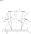
- the diffractive optical element 30 is disposed at a position where the plurality of circular laser beams IL emitted from the emission optical system 20 overlaps each other. Further, convergence angles of the plurality of circular laser beams IL are different from each other. In this case, local incidence angles of the plurality of circular laser beams IL incident on the diffractive optical element 30 are also different from each other. As shown in Fig. 4 , the local incidence angle is an incidence angle in a wavefront traveling direction when focus is locally placed on a radial cross section of a wavefront ILf of the axisymmetric circular laser beam IL, and is equal to the convergence angle of the circular laser beam IL incident on the diffractive optical element 30.
- the diffractive optical element 30 diffracts the plurality of circular laser beams IL, such that local diffraction angles of the diffracted light DL of the plurality of circular laser beams IL incident at mutually different local incidence angles are equal to each other.
- the local diffraction angle is a diffraction angle in the wavefront traveling direction when focus is locally placed on a radial cross section of a wavefront DLf of the axisymmetric diffracted light DL, and is equal to a divergence angle of the diffracted light DL emitted from the diffractive optical element 30.
- the plurality of beams of diffracted light DL emitted from the diffractive optical element 30 has the same local diffraction angle, and one beam of diffracted light DL is combined to produce a synthetic laser beam CL.
- the diffractive optical element 30 will be described later.
- the magnifying optical system 40 is provided between the diffractive optical element 30 and the condensing optical system 50, and increases an outer diameter dimension of the diffracted light DL (that is, the synthetic laser beam CL) of the plurality of circular laser beams IL diffracted by the diffractive optical element 30. A radial width (a difference between the outer diameter dimension and the inner diameter dimension) of the synthetic laser beam CL is also increased.
- the magnifying optical system 40 includes, for example, two plano-convex lenses (an incident side plano-convex lens 41 and an emission side plano-convex lens 42).
- the magnifying optical system 40 is not limited to this configuration, and alternatively, a combination of a concave lens and a convex lens, a combination of a convex mirror and a concave mirror, a combination of a concave mirror and a concave mirror, or the like can be used.
- the condensing optical system 50 is an optical system that condenses the diffracted light DL (that is, the synthetic laser beam CL) of the plurality of circular laser beams IL emitted from the diffractive optical element 30, and uses, for example, the plano-convex lens.
- the condensing optical system 50 is not limited to the plano-convex lens, and may be configured by a biconvex lens, a concave-convex lens (meniscus lens), a concave mirror, and the like.
- the laser beam combining device 10 may include a reduction optical system, a light guide optical system, and the like between the unit 22 and the condensing optical system 50, if necessary
- the reduction optical system is an optical system that reduces the diameter dimension of the circular laser beam IL emitted from the unit 22.
- the light guide optical system is an optical system that guides the circular laser beam IL emitted from the unit 22 to the condensing optical system 50.
- a cone angle ⁇ A of the first reflective surface 24a of the convex axicon mirror 24 is twice an angle ⁇ a between a rotary axis and a generating line of the cone on the first reflective surface 24a.
- a cone angle ⁇ B of the second reflective surface 23a of the concave axicon mirror 23 is twice an angle ⁇ b between a rotary axis and a generating line of the cone on the second reflective surface 23a.
- ⁇ is 1 degree or more and 10 degrees or less.
- ⁇ is - 0.1 degrees or more and 0.1 degrees or less, and is larger as the convex axicon mirror is closer to the diffractive optical element 30.
- the cone angle of the first reflective surface 24a and the cone angle of the second reflective surface 23a are different, and the difference is larger as the pair of axicon mirrors 23 and 24 is closer to the diffractive optical element 30.
- the plurality of circular laser beams IL emitted from the plurality of units 22 is emitted with mutually different diameters and at mutually different divergence angles, and then overlaps each other as being propagated.
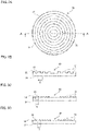
- the diffractive optical element 30 has a reflective surface (incidence surface) 32 in which a plurality of annular regions 31 that is concentric and divided by a plurality of steps is formed
- the diffractive optical element 30 has a disk shape, and a plurality of grooves 33 is provided on the reflective surface 32. The steps are formed on the reflective surface 32 by the grooves 33, and the reflective surface 32 is divided into the plurality of annular regions 31 by the steps.
- the grooves 33 are annular.
- the plurality of grooves 33 is disposed at equal intervals such that centers of the grooves coincide with each other, and is fanned such that radial dimensions (differences between outer diameter dimensions and inner diameter dimensions) of the annular regions 31 coincide with each other.
- each of the annular regions 31 between the adjacent grooves 33 may have a rectangular cross section obtained by cutting the diffractive optical element 30 in the radial direction.
- the groove 33 is provided between the adjacent annular regions 31.
- the annular regions 31 are formed so as to be flush with each other and orthogonal to a normal line of the diffractive optical element 30.
- each of the annular regions 31 formed by the groove 33 may have a sawtooth-shape cross section obtained by cutting the diffractive optical element 30 in the radial direction.
- the adjacent annular regions 31 are disposed so as to continue to each other when viewed from a direction of the normal line of the diffractive optical element 30.
- the reflective surface 32 is inclined within a section d so as to be higher as being away from a center of the diffractive optical element 30 (that is, such that the reflected beam protrudes by a larger distance in a traveling direction of the reflected beam). Further, in the annular regions 31, portions located on the same radius from the center to an outer edge of the diffractive optical element 30 are formed so as to be parallel to each other and have the same height
- the reflective surface 32 is inclined within a section d so as to be lower as being away from the center of the diffractive optical element 30 (that is, such that the reflected beam protrudes by a smaller distance in the traveling direction of the reflected beam). Further, in the annular regions 31, portions located on the same radius from the center to an outer edge of the diffractive optical element 30 are formed so as to be parallel to each other and have the same height
- a thick line with a reference sign IL in Fig. 4 imitates the wavefront ILf of the incident circular laser beam IL
- a thick line with a reference sign DL in Fig. 4 imitates the wavefront DLf of the diffracted light DL.
- the local incidence angle ⁇ n is an angle between a normal line of one of two portions of the wavefront ILf and a normal line NL of the diffractive optical element 30 in a cross section (radial cross section) in which the wavefront ILf passes through a central axis CAofthe circular laser beam ILhaving a truncated conical shape.
- the wavefront ILf having a truncated conical shape of the circular laser beam IL is axisymmetric with respect to the central axis CA, and the central axis CA is the normal line NL of the diffractive optical element 30.
- the incidence angle of the circular laser beam IL itself is therefore 0.
- the circular laser beam IL is propagated at a convergence angle ⁇ n and is incident on the diffractive optical element 30 at the local incidence angle ⁇ n. Therefore, the local incidence angle ⁇ n is synonymous with the convergence angle of the circular laser beam IL incident on the diffractive optical element 30.
- the convergence angle is a half angle of the angle of the cone (vertical angle) when the circular laser beam IL is propagated with a spot size of the circular laser beam IL (outer diameter dimension Ri of the wavefront ILf) narrowed into a conical shape toward the traveling direction.
- the convergence angle of the circular laser beam IL is represented by + (plus) when the spot size decreases (converges) toward the traveling direction, by - (minus) when the spot size increases (diverges), and by 0 (zero) when the spot size does not change.
- the convergence angle of the circular laser beam IL is also represented as a divergence angle.
- the convergence angle (divergence angle, local incidence angle) ⁇ n of the diverging circular laser beam IL has a negative (minus) value
- the convergence angle (local incidence angle) ⁇ n of the converging circular laser beam IL has a positive (plus) value.
- a direction of an arrow ⁇ n from the normal line NL of the diffractive optical element 30 represents a + (positive) direction of ⁇ n.
- the local diffraction angle ⁇ is an angle between a normal line of one of two portions of the wavefront DLf and the normal line NL of the diffractive optical element 30 in a cross section (radial cross section) in which the wavefront DLf passes through the central axis CA of the diffracted light DL having a truncated conical shape.
- the wavefront DLfhaving a truncated conical shape of the diffracted light DL is axisymmetric with the central axis CA, and the central axis CA is the normal line NL of the diffractive optical element 30.
- the diffraction angle of the diffracted light DL itself is therefore 0.
- the diffracted light DL is diffracted by the diffractive optical element 30 at the local diffraction angle ⁇ , and is emitted from the diffractive optical element 30 and propagated at the divergence angle ⁇ .
- the local diffraction angle ⁇ is synonymous with the divergence angle of the diffracted light DL emitted from the diffractive optical element 30.
- This divergence angle is a half angle of the angle of the cone (vertical angle) when the diffracted light DL is propagated with a spot size of the diffracted light DL (outer diameter dimension Rd of the wavefront DLf) expanded in a conical shape toward the traveling direction.
- the divergence angle of the diffracted light DL is represented by + (plus) when the spot size increases (diverges) toward the traveling direction, by - (minus) when the spot size decreases (converges), and by 0 (zero) when the spot size does not change.
- the divergence angle of the diffracted light DL can be expressed as a convergence angle.
- the divergence angle (local diffraction angle) ⁇ of the diverging diffracted light DL has a positive (plus) value
- the divergence angle (convergence angle, local diffraction angle) ⁇ of the converging diffracted light DL has a negative (minus) value.
- a direction of an arrow of ⁇ from the normal line NL of the diffractive optical element 30 represents a + (positive) direction of ⁇ .
- the diffraction grating equation is represented by the following equation (1).
- d is a radial distance dimension between the adjacent annular regions 31 of the diffractive optical element 30.
- d sin ⁇ n + sin ⁇ m ⁇ ⁇ n
- the circular laser beam IL of the incident light and the m-th order diffracted light DL are a specular reflection of each other in the annular region 31 on the reflective surface 32 of the diffractive optical element 30, most energy focuses on the m-th order diffracted light DL.
- n 1, 2, ...N
- a direction of an arrow of ⁇ bl from the normal line NL of the diffractive optical element 30 represents a + (positive) direction of ⁇ bl.
- ⁇ b 1 ⁇ c + ⁇ / 2
- a wavelength ⁇ n when high diffraction efficiency is obtained for m-th order diffracted light DL is represented by the following equation (3) from the above equations (1) and (2).
- the plurality of circular laser beams IL having mutually different local incidence angles ⁇ n with respect to the diffractive optical element 30 can be diffracted in accordance with the wavelength ⁇ n, such that the local diffraction angles ⁇ of the diffracted light DL coincide with each other. That is, when the diffractive optical element 30 having the above-described dimension d and the blaze angle ⁇ bl is used, the diffracted light DL having the same local diffraction angle ⁇ can be obtained from the circular laser beam IL (n: natural number) having the wavelength ⁇ n and the local incidence angle ⁇ n.
- the solid laser beam having the wavelength ⁇ n is incident on an n-th unit 22 from an n-th (n is a natural number) laser light source 21 in reverse order of proximity to the diffractive optical element 30.
- the solid laser beam passes through the first passage hole 23b of the concave axicon mirror 23, and further passes through the second passage hole 25b of the scraper mirror 25.
- the solid laser beam passes through the first passage hole 23b of the concave axicon mirror 23, and is converted into the circular laser beam IL by the first reflective surface 24a in a conical shape of the convex axicon mirror 24.
- the circular laser beam IL passes through the second passage hole 25b of the scraper mirror 25 and is reflected by the second reflective surface 23a of the concave axicon mirror 23.
- the circular laser beam IL strikes the third reflective surface 25a around the second passage hole 25b, is reflected in a direction perpendicular to the optical axis of the laser light source 21, and is emitted from the unit 22.
- the diameter dimension of the circular laser beam IL is reduced as the circular laser beam IL is propagated as shown in Fig. 1 .
- the wavefront ILf has a truncated conical shape.
- the circular laser beam IL is propagated at the angle (convergence angle) ⁇ n between the normal line of the wavefront ILf and the central axis CA.
- the outer diameter dimension Ri and the convergence angle ⁇ n are larger as being closer to the diffractive optical element 30.
- the plurality of circular laser beams IL is propagated while the optical axes coincide with each other, such that an (n + 1)-th circular laser beam IL surrounds the n-th laser beam.
- the plurality of circular laser beams IL is incident on the diffractive optical element 30 at positions where outer peripheral edges and inner peripheral edges of the plurality of circular laser beams IL coincide with and overlap each other.
- the local incidence angles ⁇ n of the plurality of circular laser beams IL are different from each other.
- the plurality of circular laser beams IL is diffracted by the diffractive optical element 30, and the m-th order (for example, first order) diffracted light DL is reflected at the local diffraction angle ⁇ .
- the diffracted light DL has a circular shape, and the wavefront DLf has a truncated conical shape.
- the diffracted light DL is propagated at an angle (divergence angle) between the normal line of the wavefront DLf and the central axis CA. This divergence angle is equal to the local diffraction angle ⁇ .
- the local diffraction angle ⁇ depends on the local incidence angle ⁇ n and the wavelength ⁇ n of the circular laser beam IL.
- the wavelength ⁇ n of the plurality of circular laser beams IL having mutually different local incidence angles ⁇ n is determined, such that the local diffraction angles ⁇ of the diffracted light DL of the circular laser beams IL coincide with each other. Therefore, a difference in the local incidence angles ⁇ n of the plurality of circular laser beams IL is canceled out by the diffractive optical element 30.
- the plurality of beams of diffracted light DL is emitted from the diffractive optical element 30 at the equal local diffraction angle ⁇ .
- the plurality of beams of diffracted light DL is combined into a single synthetic laser beam CL that is coaxial, overlaps, has the identical local diffraction angle ⁇ , and has the equal inclination of the wavefront DLf.
- the synthetic laser beam CL is magnified by the incident side plano-convex lens 41 of the magnifying optical system 40, and adjusted to a collimated state by the emission side plano-convex lens 42. Subsequently, the synthetic laser beam CL is incident on the condensing optical system 50 and is condensed. Since the divergence angles ⁇ of the plurality of beams of diffracted light DL configuring the synthetic laser beam CL are equal to each other, focal positions F of the plurality of diffracted lights DL coincide with each other. As a result, a condensing diameter of the synthetic laser beam CL can be reduced, and an irradiation power density of the synthetic laser beam CL can be enhanced
- the diameter dimension of the synthetic laser beam CL incident on the condensing optical system 50 is increased by the magnifying optical system 40.
- light condensing performance of the synthetic laser beam CL condensed by the condensing optical system 50 is enhanced, and the irradiation power density of the synthetic laser beam CL can be further improved.
- the wavelengths ⁇ n of the plurality of circular laser beams IL can be also set at equal or substantially equal intervals as shown in the above equation (3). This simplifies the configuration of the laser beam combining device 10.
- the intensity of the synthetic laser beam CL was increased 4.3 times compared with the conventional synthetic laser beam.
- the intensity of the synthetic laser beam CL was increased 4.9 times compared with the conventional synthetic laser beam.
- the synthetic laser beam CL with a high intensity even in a wide band in which the line width is about the center wavelength interval can be obtained.
- the laser beam combining device 10 uses the reflective diffractive optical element 30, but may also use a transmissive diffractive optical element 30.
- the incidence surface 32 of the transmissive diffractive optical element 30 is flat, and the plurality of concentric annular regions 31 divided by the plurality of steps is formed on the emission surface 34.
- the plurality of circular laser beams IL emitted from the emission optical system 20 is incident on the transmissive diffractive optical element 30.
- the plurality of circular laser beams IL passes through the diffractive optical element 30 and is diffracted at the emission surface 34.
- the plurality of circular laser beams IL incident at mutually different local incidence angles ⁇ n is diffracted according to the wavelength ⁇ n, such that the local diffraction angles ⁇ of the diffracted light DL coincide with each other.
- the diffracted light DL is emitted from the diffractive optical element 30 at the same local diffraction angle ⁇ and combined into the synthetic laser beam CL
- the synthetic laser beam CL is magnified by the magnifying optical system 40 and then condensed by the condensing optical system 50.
- the step is formed by the groove 33 on the reflective surface (incidence surface) 32 or the emission surface 34 of the diffractive optical element 30, and each surface 32 and 34 is divided into the plurality of annular regions 31 by the step.
- the shape of the diffractive optical element 30 is not limited to the above as long as the annular region 31 is concentric.
- the diffractive optical element 30 is not provided with the step formed by the groove 33, and may have a planar shape.
- the diffractive optical element 30 is provided with the annular region having a specific refractive index.
- the circular laser beams IL emitted from the emission optical system 20 have mutually different decrements in outer diameter dimension per unit propagation distance.
- the concentric circular laser beams IL may approach and overlap each other as being propagated
- the amounts of change in the outer diameter dimension per unit propagation distance are only required to be different from each other.
- the amount of change may be an increment instead of a decrement
- the unit 22 uses a reflection optical system including the pair of axicon minors 23 and 24.
- the unit 22 may use a transmission optical system including a pair of axicon lenses.
- the emission optical system 20 that shapes the solid laser beam into the circular laser beam IL for emission is used.
- the configuration of the emission optical system 20 is not limited to this configuration
- a scraper mirror can be used as the emission optical system 20 instead of a pair of axicon optical systems.
- the circular laser beam IL surrounds the adjacent circular laser beams IL.
- the adjacent circular laser beams IL may overlap each other.
- all the laser beams configuring the synthetic laser beam CL have a circular shape.
- the laser beam having the smallest diameter among the laser beams configuring the synthetic laser beam CL maybe solid.
- the laser beam combining device according to the present invention is useful as the laser beam combining device or the like that improves the irradiation power density of the synthetic laser beam.
Landscapes
- Physics & Mathematics (AREA)
- Optics & Photonics (AREA)
- General Physics & Mathematics (AREA)
- Engineering & Computer Science (AREA)
- Plasma & Fusion (AREA)
- Mechanical Engineering (AREA)
- Condensed Matter Physics & Semiconductors (AREA)
- Electromagnetism (AREA)
- Laser Beam Processing (AREA)
- Diffracting Gratings Or Hologram Optical Elements (AREA)
- Lenses (AREA)
- Lasers (AREA)
Claims (5)
- Laserstrahlkombiniervorrichtung, die Folgendes umfasst:ein optisches Emissionssystem, das eine Vielzahl von kreisförmigen Laserstrahlen emittiert, die sich koaxial ausbreiten und voneinander verschiedene Wellenlängen aufweisen und mit voneinander verschiedenen Divergenzen emittiert werden; undein optisches Beugungselement, das die Vielzahl von kreisförmigen Laserstrahlen gemäß den Wellenlängen der kreisförmigen Laserstrahlen beugt, so dass lokale Beugungswinkel von gebeugtem Licht der Vielzahl von kreisförmigen Laserstrahlen, die bei voneinander verschiedenen lokalen Einfallswinkeln einfallen, die den voneinander verschiedenen emittierten Divergenzen entsprechen, einander gleich sind,dadurch gekennzeichnet, dassdas optische Beugungselement ringförmige Bereiche beinhaltet, die konzentrisch sind.
- Laserstrahlkombiniervorrichtung nach Anspruch 1, wobei das optische Beugungselement an einer Position angeordnet ist, an der die Vielzahl von kreisförmigen Laserstrahlen einander überlappen.
- Laserstrahlkombiniervorrichtung nach Anspruch 1 oder 2, wobei das optische Beugungselement eine Einfallsfläche oder eine Emissionsfläche aufweist, auf der eine Vielzahl von konzentrischen und durch eine Vielzahl von Stufen unterteilten ringförmigen Bereichen ausgebildet ist.
- Laserstrahlkombiniervorrichtung nach Anspruch 3, wobei, wenn das optische Beugungselement reflektierend ist, eine Gleichung:
 wobei λn jede der Wellenlängen der Vielzahl von kreisförmigen Laserstrahlen darstellt,αn einen lokalen Einfallswinkel der Vielzahl von kreisförmigen Laserstrahlen auf das optische Beugungselement darstellt,d eine Abstandsdimension jedes der Vielzahl von ringförmigen Bereichen des optischen Beugungselements darstellt,θb1 einen Blaze-Winkel darstellt, bei dem es sich um eine Neigung jedes der ringförmigen Bereiche handelt,m eine Beugungsordnung darstellt,n eine natürliche Zahl darstellt, die jedem der kreisförmigen Laserstrahlen zugeordnet ist (n = 1, 2, ... N).N eine Anzahl der kreisförmigen Laserstrahlen darstellt, die von dem optischen Emissionssystem emittiert werden, undc einen n-Wert eines Repräsentanten der kreisförmigen Laserstrahlen darstellt und ein beliebiger Wert von (n = 1, 2, ... N) ist.
 - Laserstrahlkombiniervorrichtung nach einem der Ansprüche 1 bis 4, die weiterhin Folgendes umfasst:ein optisches Kondensorsystem, das das gebeugte Licht der Vielzahl von kreisförmigen Laserstrahlen kondensiert; undein optisches Vergrößerungssystem, das das gebeugte Licht der Vielzahl von kreisförmigen Laserstrahlen zwischen dem optischen Beugungselement und dem optischen Kondensorsystem vergrößert.
Applications Claiming Priority (2)
| Application Number | Priority Date | Filing Date | Title |
|---|---|---|---|
| JP2017150994A JP6412988B1 (ja) | 2017-08-03 | 2017-08-03 | レーザビーム合成装置 |
| PCT/JP2018/029133 WO2019027020A1 (ja) | 2017-08-03 | 2018-08-02 | レーザビーム合成装置 |
Publications (3)
| Publication Number | Publication Date |
|---|---|
| EP3663836A1 EP3663836A1 (de) | 2020-06-10 |
| EP3663836A4 EP3663836A4 (de) | 2021-04-14 |
| EP3663836B1 true EP3663836B1 (de) | 2022-06-15 |
Family
ID=63920553
Family Applications (1)
| Application Number | Title | Priority Date | Filing Date |
|---|---|---|---|
| EP18841611.9A Active EP3663836B1 (de) | 2017-08-03 | 2018-08-02 | Laserkombinierervorrichtung |
Country Status (5)
| Country | Link |
|---|---|
| US (1) | US11693250B2 (de) |
| EP (1) | EP3663836B1 (de) |
| JP (1) | JP6412988B1 (de) |
| IL (1) | IL272346B (de) |
| WO (1) | WO2019027020A1 (de) |
Families Citing this family (3)
| Publication number | Priority date | Publication date | Assignee | Title |
|---|---|---|---|---|
| US10025107B2 (en) * | 2016-02-16 | 2018-07-17 | Gerald Ho Kim | Two-dimensional coherent beam combination using circular or spiral diffraction grating |
| CN112241069A (zh) * | 2020-10-15 | 2021-01-19 | 上海无线电设备研究所 | 一种光纤激光合成系统 |
| WO2025074597A1 (ja) * | 2023-10-06 | 2025-04-10 | 三菱電機株式会社 | 円環レーザシステム |
Citations (2)
| Publication number | Priority date | Publication date | Assignee | Title |
|---|---|---|---|---|
| EP0137976A2 (de) * | 1983-10-13 | 1985-04-24 | The Perkin-Elmer Corporation | Interferometrische Messtechnik von Oberflächenformen |
| JPH10134401A (ja) * | 1996-10-31 | 1998-05-22 | Sony Corp | 光学ピックアップ装置 |
Family Cites Families (10)
| Publication number | Priority date | Publication date | Assignee | Title |
|---|---|---|---|---|
| US20030021032A1 (en) * | 2001-06-22 | 2003-01-30 | Cyrus Bamji | Method and system to display a virtual input device |
| JP2007121899A (ja) * | 2005-10-31 | 2007-05-17 | Minebea Co Ltd | 光路合成装置および光ビーム合成方法 |
| JP6391904B2 (ja) * | 2011-11-11 | 2018-09-19 | ソニー株式会社 | 半導体レーザ装置組立体 |
| TW201401699A (zh) * | 2012-04-09 | 2014-01-01 | Sony Corp | 半導體雷射裝置組立體 |
| US9690107B2 (en) * | 2013-03-15 | 2017-06-27 | Trumpf Laser Gmbh | Device for wavelength combining of laser beams |
| JP5603992B1 (ja) * | 2013-10-29 | 2014-10-08 | 川崎重工業株式会社 | レーザビーム合成装置 |
| JP2016076520A (ja) * | 2014-10-02 | 2016-05-12 | 株式会社ディスコ | ウエーハの加工方法 |
| JP6267620B2 (ja) * | 2014-10-06 | 2018-01-24 | 川崎重工業株式会社 | レーザビーム合成装置 |
| JP2016112609A (ja) * | 2014-12-18 | 2016-06-23 | パナソニックIpマネジメント株式会社 | レーザ切断装置およびレーザ切断方法 |
| US10025107B2 (en) * | 2016-02-16 | 2018-07-17 | Gerald Ho Kim | Two-dimensional coherent beam combination using circular or spiral diffraction grating |
-
2017
- 2017-08-03 JP JP2017150994A patent/JP6412988B1/ja active Active
-
2018
- 2018-08-02 WO PCT/JP2018/029133 patent/WO2019027020A1/ja not_active Ceased
- 2018-08-02 EP EP18841611.9A patent/EP3663836B1/de active Active
-
2020
- 2020-01-29 IL IL272346A patent/IL272346B/en unknown
- 2020-01-30 US US16/776,532 patent/US11693250B2/en active Active
Patent Citations (2)
| Publication number | Priority date | Publication date | Assignee | Title |
|---|---|---|---|---|
| EP0137976A2 (de) * | 1983-10-13 | 1985-04-24 | The Perkin-Elmer Corporation | Interferometrische Messtechnik von Oberflächenformen |
| JPH10134401A (ja) * | 1996-10-31 | 1998-05-22 | Sony Corp | 光学ピックアップ装置 |
Also Published As
| Publication number | Publication date |
|---|---|
| EP3663836A1 (de) | 2020-06-10 |
| US11693250B2 (en) | 2023-07-04 |
| JP2019028401A (ja) | 2019-02-21 |
| WO2019027020A1 (ja) | 2019-02-07 |
| IL272346A (en) | 2020-03-31 |
| IL272346B (en) | 2022-03-01 |
| EP3663836A4 (de) | 2021-04-14 |
| US20200166763A1 (en) | 2020-05-28 |
| JP6412988B1 (ja) | 2018-10-24 |
Similar Documents
| Publication | Publication Date | Title |
|---|---|---|
| EP3470910B1 (de) | Vorrichtung für laserstrahlsynthese | |
| US2356654A (en) | Catadioptric lens | |
| JP3370612B2 (ja) | 光強度変換素子、コリメートレンズ、対物レンズ及び光学装置 | |
| US11693250B2 (en) | Laser beam combining device | |
| US20140003456A1 (en) | Device For Converting The Profile of a Laser Beam Into a Laser Beam With a Rotationally Symmetrical Intensity Distribution | |
| JP6267620B2 (ja) | レーザビーム合成装置 | |
| US4696572A (en) | Surface inspection apparatus | |
| KR20120018184A (ko) | 여기 광을 주입하고 샘플로부터 비-탄성 산란광을 수집하는 전반사 장치 | |
| US9454132B2 (en) | Integrated hologram optical device | |
| US7548376B2 (en) | Total internal reflection micro lens array | |
| US20060233492A1 (en) | Optical beam combiner/concentrator | |
| US9798047B2 (en) | Device for applying light to an inner surface of a cylinder and beam transformation device for such a device | |
| CN111148986A (zh) | 一种紧凑型传感器件 | |
| JP2018156008A (ja) | 受光光学系 | |
| US6791755B2 (en) | Optical device for making light converge | |
| US12032183B2 (en) | Spatial frequency filter device for use with a laser beam, spatial frequency filter assembly having such a spatial frequency filter device, and method for spatial frequency filtering of a laser beam | |
| US11947104B2 (en) | Reflective spiral phase plate, and apparatus for generating Laguerre Gaussian beam comprising same | |
| KR20190039453A (ko) | 화상 표시 장치 | |
| KR102046103B1 (ko) | 집적 홀로그램 광학소자 | |
| JPH06300897A (ja) | X線光学装置 | |
| JP2015014491A (ja) | X線集光装置およびx線装置 | |
| EP2722694A1 (de) | Optisches Element mit Brechung mehrfacher Ordnung für die Konzentrierung einer Breitband-Elektromagnetstrahlung | |
| JP2004173054A (ja) | 分散補償器及び分散補償システム | |
| JP2009121952A (ja) | 光学系のアライメント装置および方法 |
Legal Events
| Date | Code | Title | Description |
|---|---|---|---|
| STAA | Information on the status of an ep patent application or granted ep patent |
Free format text: STATUS: THE INTERNATIONAL PUBLICATION HAS BEEN MADE |
|
| PUAI | Public reference made under article 153(3) epc to a published international application that has entered the european phase |
Free format text: ORIGINAL CODE: 0009012 |
|
| STAA | Information on the status of an ep patent application or granted ep patent |
Free format text: STATUS: REQUEST FOR EXAMINATION WAS MADE |
|
| 17P | Request for examination filed |
Effective date: 20200123 |
|
| AK | Designated contracting states |
Kind code of ref document: A1 Designated state(s): AL AT BE BG CH CY CZ DE DK EE ES FI FR GB GR HR HU IE IS IT LI LT LU LV MC MK MT NL NO PL PT RO RS SE SI SK SM TR |
|
| AX | Request for extension of the european patent |
Extension state: BA ME |
|
| DAV | Request for validation of the european patent (deleted) | ||
| DAX | Request for extension of the european patent (deleted) | ||
| A4 | Supplementary search report drawn up and despatched |
Effective date: 20210317 |
|
| RIC1 | Information provided on ipc code assigned before grant |
Ipc: G02B 27/10 20060101AFI20210311BHEP Ipc: B23K 26/064 20140101ALI20210311BHEP Ipc: G02B 5/18 20060101ALI20210311BHEP Ipc: G02B 13/00 20060101ALI20210311BHEP Ipc: G02B 13/18 20060101ALI20210311BHEP Ipc: G02B 27/40 20060101ALI20210311BHEP Ipc: G02B 27/42 20060101ALI20210311BHEP |
|
| GRAP | Despatch of communication of intention to grant a patent |
Free format text: ORIGINAL CODE: EPIDOSNIGR1 |
|
| STAA | Information on the status of an ep patent application or granted ep patent |
Free format text: STATUS: GRANT OF PATENT IS INTENDED |
|
| INTG | Intention to grant announced |
Effective date: 20220404 |
|
| GRAS | Grant fee paid |
Free format text: ORIGINAL CODE: EPIDOSNIGR3 |
|
| GRAA | (expected) grant |
Free format text: ORIGINAL CODE: 0009210 |
|
| STAA | Information on the status of an ep patent application or granted ep patent |
Free format text: STATUS: THE PATENT HAS BEEN GRANTED |
|
| AK | Designated contracting states |
Kind code of ref document: B1 Designated state(s): AL AT BE BG CH CY CZ DE DK EE ES FI FR GB GR HR HU IE IS IT LI LT LU LV MC MK MT NL NO PL PT RO RS SE SI SK SM TR |
|
| REG | Reference to a national code |
Ref country code: CH Ref legal event code: EP Ref country code: GB Ref legal event code: FG4D |
|
| REG | Reference to a national code |
Ref country code: IE Ref legal event code: FG4D |
|
| REG | Reference to a national code |
Ref country code: DE Ref legal event code: R096 Ref document number: 602018036858 Country of ref document: DE |
|
| REG | Reference to a national code |
Ref country code: AT Ref legal event code: REF Ref document number: 1498722 Country of ref document: AT Kind code of ref document: T Effective date: 20220715 |
|
| REG | Reference to a national code |
Ref country code: LT Ref legal event code: MG9D |
|
| REG | Reference to a national code |
Ref country code: NL Ref legal event code: MP Effective date: 20220615 |
|
| PG25 | Lapsed in a contracting state [announced via postgrant information from national office to epo] |
Ref country code: SE Free format text: LAPSE BECAUSE OF FAILURE TO SUBMIT A TRANSLATION OF THE DESCRIPTION OR TO PAY THE FEE WITHIN THE PRESCRIBED TIME-LIMIT Effective date: 20220615 Ref country code: NO Free format text: LAPSE BECAUSE OF FAILURE TO SUBMIT A TRANSLATION OF THE DESCRIPTION OR TO PAY THE FEE WITHIN THE PRESCRIBED TIME-LIMIT Effective date: 20220915 Ref country code: LT Free format text: LAPSE BECAUSE OF FAILURE TO SUBMIT A TRANSLATION OF THE DESCRIPTION OR TO PAY THE FEE WITHIN THE PRESCRIBED TIME-LIMIT Effective date: 20220615 Ref country code: HR Free format text: LAPSE BECAUSE OF FAILURE TO SUBMIT A TRANSLATION OF THE DESCRIPTION OR TO PAY THE FEE WITHIN THE PRESCRIBED TIME-LIMIT Effective date: 20220615 Ref country code: GR Free format text: LAPSE BECAUSE OF FAILURE TO SUBMIT A TRANSLATION OF THE DESCRIPTION OR TO PAY THE FEE WITHIN THE PRESCRIBED TIME-LIMIT Effective date: 20220916 Ref country code: FI Free format text: LAPSE BECAUSE OF FAILURE TO SUBMIT A TRANSLATION OF THE DESCRIPTION OR TO PAY THE FEE WITHIN THE PRESCRIBED TIME-LIMIT Effective date: 20220615 Ref country code: BG Free format text: LAPSE BECAUSE OF FAILURE TO SUBMIT A TRANSLATION OF THE DESCRIPTION OR TO PAY THE FEE WITHIN THE PRESCRIBED TIME-LIMIT Effective date: 20220915 |
|
| REG | Reference to a national code |
Ref country code: AT Ref legal event code: MK05 Ref document number: 1498722 Country of ref document: AT Kind code of ref document: T Effective date: 20220615 |
|
| PG25 | Lapsed in a contracting state [announced via postgrant information from national office to epo] |
Ref country code: RS Free format text: LAPSE BECAUSE OF FAILURE TO SUBMIT A TRANSLATION OF THE DESCRIPTION OR TO PAY THE FEE WITHIN THE PRESCRIBED TIME-LIMIT Effective date: 20220615 Ref country code: LV Free format text: LAPSE BECAUSE OF FAILURE TO SUBMIT A TRANSLATION OF THE DESCRIPTION OR TO PAY THE FEE WITHIN THE PRESCRIBED TIME-LIMIT Effective date: 20220615 |
|
| PG25 | Lapsed in a contracting state [announced via postgrant information from national office to epo] |
Ref country code: NL Free format text: LAPSE BECAUSE OF FAILURE TO SUBMIT A TRANSLATION OF THE DESCRIPTION OR TO PAY THE FEE WITHIN THE PRESCRIBED TIME-LIMIT Effective date: 20220615 |
|
| PG25 | Lapsed in a contracting state [announced via postgrant information from national office to epo] |
Ref country code: SM Free format text: LAPSE BECAUSE OF FAILURE TO SUBMIT A TRANSLATION OF THE DESCRIPTION OR TO PAY THE FEE WITHIN THE PRESCRIBED TIME-LIMIT Effective date: 20220615 Ref country code: SK Free format text: LAPSE BECAUSE OF FAILURE TO SUBMIT A TRANSLATION OF THE DESCRIPTION OR TO PAY THE FEE WITHIN THE PRESCRIBED TIME-LIMIT Effective date: 20220615 Ref country code: RO Free format text: LAPSE BECAUSE OF FAILURE TO SUBMIT A TRANSLATION OF THE DESCRIPTION OR TO PAY THE FEE WITHIN THE PRESCRIBED TIME-LIMIT Effective date: 20220615 Ref country code: PT Free format text: LAPSE BECAUSE OF FAILURE TO SUBMIT A TRANSLATION OF THE DESCRIPTION OR TO PAY THE FEE WITHIN THE PRESCRIBED TIME-LIMIT Effective date: 20221017 Ref country code: ES Free format text: LAPSE BECAUSE OF FAILURE TO SUBMIT A TRANSLATION OF THE DESCRIPTION OR TO PAY THE FEE WITHIN THE PRESCRIBED TIME-LIMIT Effective date: 20220615 Ref country code: EE Free format text: LAPSE BECAUSE OF FAILURE TO SUBMIT A TRANSLATION OF THE DESCRIPTION OR TO PAY THE FEE WITHIN THE PRESCRIBED TIME-LIMIT Effective date: 20220615 Ref country code: CZ Free format text: LAPSE BECAUSE OF FAILURE TO SUBMIT A TRANSLATION OF THE DESCRIPTION OR TO PAY THE FEE WITHIN THE PRESCRIBED TIME-LIMIT Effective date: 20220615 Ref country code: AT Free format text: LAPSE BECAUSE OF FAILURE TO SUBMIT A TRANSLATION OF THE DESCRIPTION OR TO PAY THE FEE WITHIN THE PRESCRIBED TIME-LIMIT Effective date: 20220615 |
|
| PG25 | Lapsed in a contracting state [announced via postgrant information from national office to epo] |
Ref country code: PL Free format text: LAPSE BECAUSE OF FAILURE TO SUBMIT A TRANSLATION OF THE DESCRIPTION OR TO PAY THE FEE WITHIN THE PRESCRIBED TIME-LIMIT Effective date: 20220615 Ref country code: IS Free format text: LAPSE BECAUSE OF FAILURE TO SUBMIT A TRANSLATION OF THE DESCRIPTION OR TO PAY THE FEE WITHIN THE PRESCRIBED TIME-LIMIT Effective date: 20221015 |
|
| REG | Reference to a national code |
Ref country code: DE Ref legal event code: R097 Ref document number: 602018036858 Country of ref document: DE |
|
| PG25 | Lapsed in a contracting state [announced via postgrant information from national office to epo] |
Ref country code: AL Free format text: LAPSE BECAUSE OF FAILURE TO SUBMIT A TRANSLATION OF THE DESCRIPTION OR TO PAY THE FEE WITHIN THE PRESCRIBED TIME-LIMIT Effective date: 20220615 |
|
| REG | Reference to a national code |
Ref country code: CH Ref legal event code: PL |
|
| PLBE | No opposition filed within time limit |
Free format text: ORIGINAL CODE: 0009261 |
|
| STAA | Information on the status of an ep patent application or granted ep patent |
Free format text: STATUS: NO OPPOSITION FILED WITHIN TIME LIMIT |
|
| PG25 | Lapsed in a contracting state [announced via postgrant information from national office to epo] |
Ref country code: LU Free format text: LAPSE BECAUSE OF NON-PAYMENT OF DUE FEES Effective date: 20220802 Ref country code: LI Free format text: LAPSE BECAUSE OF NON-PAYMENT OF DUE FEES Effective date: 20220831 Ref country code: DK Free format text: LAPSE BECAUSE OF FAILURE TO SUBMIT A TRANSLATION OF THE DESCRIPTION OR TO PAY THE FEE WITHIN THE PRESCRIBED TIME-LIMIT Effective date: 20220615 Ref country code: CH Free format text: LAPSE BECAUSE OF NON-PAYMENT OF DUE FEES Effective date: 20220831 |
|
| REG | Reference to a national code |
Ref country code: BE Ref legal event code: MM Effective date: 20220831 |
|
| 26N | No opposition filed |
Effective date: 20230316 |
|
| PG25 | Lapsed in a contracting state [announced via postgrant information from national office to epo] |
Ref country code: SI Free format text: LAPSE BECAUSE OF FAILURE TO SUBMIT A TRANSLATION OF THE DESCRIPTION OR TO PAY THE FEE WITHIN THE PRESCRIBED TIME-LIMIT Effective date: 20220615 |
|
| P01 | Opt-out of the competence of the unified patent court (upc) registered |
Effective date: 20230611 |
|
| PG25 | Lapsed in a contracting state [announced via postgrant information from national office to epo] |
Ref country code: IE Free format text: LAPSE BECAUSE OF NON-PAYMENT OF DUE FEES Effective date: 20220802 Ref country code: FR Free format text: LAPSE BECAUSE OF NON-PAYMENT OF DUE FEES Effective date: 20220815 |
|
| PG25 | Lapsed in a contracting state [announced via postgrant information from national office to epo] |
Ref country code: BE Free format text: LAPSE BECAUSE OF NON-PAYMENT OF DUE FEES Effective date: 20220831 |
|
| PG25 | Lapsed in a contracting state [announced via postgrant information from national office to epo] |
Ref country code: IT Free format text: LAPSE BECAUSE OF FAILURE TO SUBMIT A TRANSLATION OF THE DESCRIPTION OR TO PAY THE FEE WITHIN THE PRESCRIBED TIME-LIMIT Effective date: 20220615 |
|
| PG25 | Lapsed in a contracting state [announced via postgrant information from national office to epo] |
Ref country code: MK Free format text: LAPSE BECAUSE OF FAILURE TO SUBMIT A TRANSLATION OF THE DESCRIPTION OR TO PAY THE FEE WITHIN THE PRESCRIBED TIME-LIMIT Effective date: 20220615 Ref country code: CY Free format text: LAPSE BECAUSE OF FAILURE TO SUBMIT A TRANSLATION OF THE DESCRIPTION OR TO PAY THE FEE WITHIN THE PRESCRIBED TIME-LIMIT Effective date: 20220615 |
|
| PG25 | Lapsed in a contracting state [announced via postgrant information from national office to epo] |
Ref country code: HU Free format text: LAPSE BECAUSE OF FAILURE TO SUBMIT A TRANSLATION OF THE DESCRIPTION OR TO PAY THE FEE WITHIN THE PRESCRIBED TIME-LIMIT; INVALID AB INITIO Effective date: 20180802 |
|
| PG25 | Lapsed in a contracting state [announced via postgrant information from national office to epo] |
Ref country code: MC Free format text: LAPSE BECAUSE OF FAILURE TO SUBMIT A TRANSLATION OF THE DESCRIPTION OR TO PAY THE FEE WITHIN THE PRESCRIBED TIME-LIMIT Effective date: 20220615 |
|
| PG25 | Lapsed in a contracting state [announced via postgrant information from national office to epo] |
Ref country code: TR Free format text: LAPSE BECAUSE OF FAILURE TO SUBMIT A TRANSLATION OF THE DESCRIPTION OR TO PAY THE FEE WITHIN THE PRESCRIBED TIME-LIMIT Effective date: 20220615 Ref country code: MC Free format text: LAPSE BECAUSE OF FAILURE TO SUBMIT A TRANSLATION OF THE DESCRIPTION OR TO PAY THE FEE WITHIN THE PRESCRIBED TIME-LIMIT Effective date: 20220615 |
|
| PG25 | Lapsed in a contracting state [announced via postgrant information from national office to epo] |
Ref country code: MT Free format text: LAPSE BECAUSE OF FAILURE TO SUBMIT A TRANSLATION OF THE DESCRIPTION OR TO PAY THE FEE WITHIN THE PRESCRIBED TIME-LIMIT Effective date: 20220615 |
|
| PG25 | Lapsed in a contracting state [announced via postgrant information from national office to epo] |
Ref country code: BG Free format text: LAPSE BECAUSE OF FAILURE TO SUBMIT A TRANSLATION OF THE DESCRIPTION OR TO PAY THE FEE WITHIN THE PRESCRIBED TIME-LIMIT Effective date: 20220615 |
|
| PG25 | Lapsed in a contracting state [announced via postgrant information from national office to epo] |
Ref country code: BG Free format text: LAPSE BECAUSE OF FAILURE TO SUBMIT A TRANSLATION OF THE DESCRIPTION OR TO PAY THE FEE WITHIN THE PRESCRIBED TIME-LIMIT Effective date: 20220615 |
|
| PGFP | Annual fee paid to national office [announced via postgrant information from national office to epo] |
Ref country code: DE Payment date: 20250702 Year of fee payment: 8 |
|
| PGFP | Annual fee paid to national office [announced via postgrant information from national office to epo] |
Ref country code: GB Payment date: 20250703 Year of fee payment: 8 |