EP3663835B1 - Am kopf montierte anzeige und verfahren zum entwurf einer weitfokuslinse für die am kopf montierte anzeige - Google Patents
Am kopf montierte anzeige und verfahren zum entwurf einer weitfokuslinse für die am kopf montierte anzeige Download PDFInfo
- Publication number
- EP3663835B1 EP3663835B1 EP19805873.7A EP19805873A EP3663835B1 EP 3663835 B1 EP3663835 B1 EP 3663835B1 EP 19805873 A EP19805873 A EP 19805873A EP 3663835 B1 EP3663835 B1 EP 3663835B1
- Authority
- EP
- European Patent Office
- Prior art keywords
- right eye
- left eye
- eye
- wide
- virtual image
- Prior art date
- Legal status (The legal status is an assumption and is not a legal conclusion. Google has not performed a legal analysis and makes no representation as to the accuracy of the status listed.)
- Active
Links
Images


Classifications
-
- G—PHYSICS
- G02—OPTICS
- G02B—OPTICAL ELEMENTS, SYSTEMS OR APPARATUS
- G02B27/00—Optical systems or apparatus not provided for by any of the groups G02B1/00 - G02B26/00, G02B30/00
- G02B27/01—Head-up displays
- G02B27/017—Head mounted
- G02B27/0172—Head mounted characterised by optical features
-
- G—PHYSICS
- G02—OPTICS
- G02B—OPTICAL ELEMENTS, SYSTEMS OR APPARATUS
- G02B25/00—Eyepieces; Magnifying glasses
- G02B25/001—Eyepieces
-
- G—PHYSICS
- G02—OPTICS
- G02B—OPTICAL ELEMENTS, SYSTEMS OR APPARATUS
- G02B27/00—Optical systems or apparatus not provided for by any of the groups G02B1/00 - G02B26/00, G02B30/00
- G02B27/0012—Optical design, e.g. procedures, algorithms, optimisation routines
-
- G—PHYSICS
- G02—OPTICS
- G02B—OPTICAL ELEMENTS, SYSTEMS OR APPARATUS
- G02B27/00—Optical systems or apparatus not provided for by any of the groups G02B1/00 - G02B26/00, G02B30/00
- G02B27/0075—Optical systems or apparatus not provided for by any of the groups G02B1/00 - G02B26/00, G02B30/00 with means for altering, e.g. increasing, the depth of field or depth of focus
-
- G—PHYSICS
- G02—OPTICS
- G02B—OPTICAL ELEMENTS, SYSTEMS OR APPARATUS
- G02B3/00—Simple or compound lenses
- G02B3/02—Simple or compound lenses with non-spherical faces
-
- G—PHYSICS
- G02—OPTICS
- G02C—SPECTACLES; SUNGLASSES OR GOGGLES INSOFAR AS THEY HAVE THE SAME FEATURES AS SPECTACLES; CONTACT LENSES
- G02C11/00—Non-optical adjuncts; Attachment thereof
- G02C11/10—Electronic devices other than hearing aids
-
- G—PHYSICS
- G02—OPTICS
- G02C—SPECTACLES; SUNGLASSES OR GOGGLES INSOFAR AS THEY HAVE THE SAME FEATURES AS SPECTACLES; CONTACT LENSES
- G02C7/00—Optical parts
- G02C7/02—Lenses; Lens systems ; Methods of designing lenses
- G02C7/022—Ophthalmic lenses having special refractive features achieved by special materials or material structures
-
- G—PHYSICS
- G02—OPTICS
- G02B—OPTICAL ELEMENTS, SYSTEMS OR APPARATUS
- G02B3/00—Simple or compound lenses
- G02B2003/0093—Simple or compound lenses characterised by the shape
-
- G—PHYSICS
- G02—OPTICS
- G02B—OPTICAL ELEMENTS, SYSTEMS OR APPARATUS
- G02B27/00—Optical systems or apparatus not provided for by any of the groups G02B1/00 - G02B26/00, G02B30/00
- G02B27/01—Head-up displays
- G02B27/0101—Head-up displays characterised by optical features
- G02B2027/0132—Head-up displays characterised by optical features comprising binocular systems
-
- G—PHYSICS
- G02—OPTICS
- G02B—OPTICAL ELEMENTS, SYSTEMS OR APPARATUS
- G02B27/00—Optical systems or apparatus not provided for by any of the groups G02B1/00 - G02B26/00, G02B30/00
- G02B27/01—Head-up displays
- G02B27/017—Head mounted
- G02B27/0172—Head mounted characterised by optical features
- G02B2027/0174—Head mounted characterised by optical features holographic
-
- G—PHYSICS
- G02—OPTICS
- G02C—SPECTACLES; SUNGLASSES OR GOGGLES INSOFAR AS THEY HAVE THE SAME FEATURES AS SPECTACLES; CONTACT LENSES
- G02C2202/00—Generic optical aspects applicable to one or more of the subgroups of G02C7/00
- G02C2202/24—Myopia progression prevention
Definitions
- the present invention relates to a head-mounted display and a method for designing a wide-focus lens to be used for the head-mounted display.
- both eyeballs rotate and capture a stereoscopic image, and accordingly, a depth of the stereoscopic image is correctly perceived by vergence, and on the other hand, both eyes are focused on the display displaying the parallax images, so that the depth of the stereoscopic image cannot be correctly perceived by accommodation. Therefore, due to the interaction of vergence and accommodation, vergence accommodation to guide focusing of the eyes to a depth perceived by vergence cannot function for a stereoscopic image displayed by a binocular stereoscopic display. In this way, it is said that visual fatigue is caused by conflict between vergence and accommodation.
- a virtual image is formed at a far side ranging from a position several meters ahead to infinity, and a stereoscopic image is displayed in a hand working space at a near side and the stereoscopic image is interactively manipulated, and conflict between vergence and accommodation is more severe.
- Non-Patent Literature 1 discloses an HMD that enables focusing of the eyes on a stereoscopic image by being provided with a virtual image forming system including a variable-focal-length mirror and a display for each of the left and right eyes, and forming a virtual image of an image on the display at a plurality of different depth positions by using the variable-focal-length mirrors.
- a DMD Digital Micromirror Device
- the HMD having this configuration not only increases the cost due to use of variable-focal-length mirrors but also requires a display that operates at a high speed.
- an image processing device that generates, at a high speed, images divided in a depth direction to be displayed on the high-speed display is required.
- Non-Patent Literature 2 describes an HMD that dynamically changes the virtual image forming relationship by using a variable-focal-length lens and a motor in a virtual image forming system including a display, and rotation angles of the left and right eyes are detected and a depth to be perceived by vergence is calculated, and the image forming relationship in the image forming system is changed so that a virtual image of an image on the display is formed at this depth position.
- the HMD having this configuration requires a means to detect rotation angles of the eyes.
- use of a mechanical mechanism including a variable-focal-length lens results in an increase in cost and weight caused by use of the mechanism which becomes problematic.
- Patent Literature 3 discloses a vision correction lens which is made by adding a depth of focus extension component represented by Ar3, where r represents the distance from the Z-axis and A represents a constant, to a Z-coordinate value on a refractive surface determined on the basis of a prescription power, when the Z axis represents a longitudinal axis passing through the geometric center of the lens, and a direction toward the back of the lens is the positive Z axis to increase a depth of focus in the darkness.
- Patent Literature 4 discloses a stereoscopic picture display device including a display for displaying a left-eye picture and a right-eye picture to provide a both-eye parallax.
- Patent Literature 5 discloses spectacles for stereoscopic video observation including lenses for stereoscopic video observation for observing a stereoscopic video and lenses for refraction correction having the degree of prescription corresponding to a user.
- the lenses for refraction correction are installed in at least either one face at a user side or the other face at a display part side in the lenses for stereoscopic video observation.
- an opposed face which is opposed to one face or the other face of the lenses for stereoscopic video observation in the lenses for refraction correction is formed so as to be shaped following the opposed face in the lenses for stereoscopic video observation.
- Patent Literature 6 discloses a hybrid optical system for a head wearable display including a central vision lens and a peripheral vision lens.
- the central vision lens approximately aligns with a cornea of a user to provide lensing to a central vision of the user when the user is looking straight forward.
- the peripheral vision lens provides lensing to an extended field of view that extends angularly beyond the central vision lensed by the central vision lens when the user is looking straight forward.
- Non-Patent Literature 3 discloses a varifocal system for Virtual Reality Head-Mounted Displays (VR HMDs).
- the system includes a focus-adjustable optical system based on Alvarez lenses which include two saddle-shaped lens elements which are adjustable by translating the saddle-shaped lens elements in a direction perpendicular to the optical axis.
- the system further includes an eye tracker to estimate the gaze direction of the user and an adaptive optics module to adjust the focus of the Alvarez lenses by translating the saddle-shaped lens elements.
- Non-Patent Literature 4 discloses a varifocal optical see-through head-mounted display system using Alvarez lenses to dynamically shift the focus of the virtual image plane from 0-3 diopters.
- an object of the present invention is to provide a head-mounted display that enables viewing of a stereoscopic image without visual fatigue caused by vergence-accommodation conflict by a simpler configuration, and a method for designing a wide-focus lens to be used for the head-mounted display.
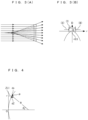
- Fig. 1 shows an outline configuration of an HMD for VR (simply referred to as an HMD, unless otherwise confusing) according to a first embodiment.
- the left eye Ea and the right eye Eb of a user are arranged in an up-down direction of the drawings, and this direction is defined as a left-right direction, and the left-right direction of the drawings is defined as an anteroposterior direction.
- a reference line passing through the center between the left eye Ea and the right eye Eb and extending in the anteroposterior direction is defined as a centerline L
- reference lines respectively extending parallel to the centerline L from the left eye Ea and the right eye Eb are defined as main visual lines La and Lb.
- a separation distance between the left eye Ea and the right eye Eb of the user is defined as a separation distance P, and is provided by using, for example, an average separation distance between the left and right eyes of adults (typically 65 mm).
- the HMD 1 includes a frame 2, a display device 3, virtual image forming optical systems 4a and 4b for the left eye and the right eye, wide-focus lenses 5a and 5b for the left eye and the right eye, and actuators 6a and 6b.
- the virtual image on the virtual image display plane Va is viewed with the left eye Ea, and at the same time, the virtual image on the virtual image display plane Vb is viewed with the right eye Eb, and accordingly, the virtual images can be stereoscopically viewed inside a region As in which the overlap region is viewable from both eyes. That is, a stereoscopic image is projected inside the region As.
- the wide-focus lenses 5a and 5b for the left eye and the right eye are wide-focus lenses having a negative focal length with a range.
- the wide-focus lenses 5a and 5b for the left eye and the right eye are respectively disposed with respect to the virtual image forming optical systems 4a and 4b for the left eye and the right eye so as to overlap optical axis directions of the virtual image forming optical systems 4a and 4b for the left eye and the right eye.
- virtual images of the images 3a and 3b for the left eye and the right eye formed by the virtual image forming optical systems 4a and 4b for the left eye and the right eye are formed in a range with a width extending in the optical axis directions at the further side and/or the nearer side than the virtual image display planes Va and Vb since the focal lengths of the wide-focus lenses 5a and 5b for the left eye and the right eye have a range.
- the focal lengths of the wide-focus lenses 5a and 5b for the left eye and the right eye are determined so as to enable viewing of a stereoscopic image without visual fatigue caused by vergence-accommodation conflict.
- Fig. 2 shows a relationship between vergence and accommodation to enable comfortable stereovision.
- vergence and accommodation match each other, however, from studies on visual fatigue, it is known that, even if they do not match each other, there is a permissible amount of mismatch to some extent ( T. Shibata, J. Kim, D. M. Hoffman, M. S. Banks, "The zone of comfort: Predicting visual discomfort with stereo displays," J. Vision, vol. 11, no. 8, p. 1-29 (2011 )).
- the permissible amount of mismatch between vergence and accommodation can be expressed by using a far end D far and a near end D near of a focal position of the eyes with respect to a depth Dv perceived by vergence.
- D far , D near , and Dv are provided in units of diopter (Diopter [D]) which is a reciprocal of a focal length measured in meters.
- a mismatch between vergence and accommodation is permitted.
- a corresponding range of a depth Dv perceived by vergence is 0.051 to 1.1 D (0.92 to 19 m). That is, in a case where the virtual image display planes Va and Vb are at 2m distances from the left eye Ea and the right eye Eb, when a stereoscopic image is displayed in a range of 0.92 to 19 m, the stereoscopic image can be comfortably viewed without experiencing visual fatigue caused by vergence-accommodation conflict.
- a range of comfortable stereovision sufficiently extends to the further side than the virtual image display planes Va and Vb, but does not sufficiently extend to the nearer side.
- virtual images are formed at the far side ranging from several meters (typically 2 m) ahead of the left eye Ea and the right eye Eb to infinity, and a stereoscopic image is formed in a working space that spread in front of the user (typically, a region of approximately 60 cm from the left eye Ea and the right eye Eb) and the stereoscopic image is interactively manipulated, so that in stereoscopic display of the HMD 1, it is preferable that the range of comfortable stereovision is expanded to the near side.
- wide-focus lenses 5a and 5b for the left eye and the right eye having a negative focal length are used.
- the range of the focal lengths of the wide-focus lenses 5a, 5b for the left eye and the right eye is set from f 1 to f 2
- a distance from the wide-focus lenses 5a and 5b for the left eye and the right eye to the virtual image display planes Va and Vb is defined as l 0 .
- a permissible range of vergence obtained by using D far and D near is expanded to the near side and becomes 0.64 to 19 m (0.051 to 1.6 D), and comfortable stereovision is enabled in a working space that spreads in front of a user.
- Fig. 3 shows a shape (A) of the wide-focus lenses 5a, 5b for the left eye or the right eye, and a distribution (B) of focal length with respect to a distance from the center.
- the focal length is expressed by refractive power as a reciprocal of the focal length.
- the wide-focus lens has refractive power the value of which is negative and minimum in absolute value and includes zero at the optical center, and becomes increasingly negative and larger in absolute value with an increasing distance from the optical center.
- axicon G. Mikula, Z. Jaroszewicz, A. Kolodziejczyk, K. Petelczyc, and M. Sypek, "Images with extended focal depth by means of lenses with radial and angular modulation," Opt. Express, vol. 15, no. 15, p. 9184-9193 (2007 )), axilens ( J. Sochacki, A. Kolodziejczyk, Z. Jaroszewicz, and S. Bara, "Nonparaxial design of generalized axicons," Appl. Opt., vol. 31, p. 5326-5330 (1992 )), light sword optical element ( N. Davidson, A. A.
- Equation (3) described above is derived as follows.
- Fig. 4 shows a surface shape of the wide-focus lens.
- Optical centers of the wide-focus lenses 5a and 5b for the left eye and the right eye are respectively disposed by being shifted toward the center side between the lenses in the left-right direction, that is, toward the centerline L with respect to the optical centers (that is, optical axes) of the virtual image forming optical systems 4a and 4b for the left eye and the right eye.
- shift amounts ⁇ of the respective optical centers of the wide-focus lenses 5a and 5b for the left eye and the right eye with respect to the optical axes of the virtual image forming optical systems 4a and 4b for the left eye and the right eye are determined.
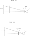
- Fig. 5A shows, as a comparative example, a relationship between an angle of a visual line and a position that the visual line passes through inside the wide-focus lenses 5a, 5b in a stereoscopic display device with a small angle of view such as a 3D movie or a stereoscopic television.
- a user wears stereoscopic glasses to which wide-focus lenses 5a and 5b and a filter F are attached, and views a stereoscopic image by viewing a display surface D through the stereoscopic glasses.
- the filter F is an optical element for separating images for the left eye and the right eye, such as a polarization filter, a liquid crystal shutter, a chromatic filter, a spectral filter, etc. At this time, light that exits from the display surface D enters the left eye Ea and the right eye Eb through the wide-focus lenses 5a and 5b.
- distances from the wide-focus lenses 5a and 5b to the display surface D can be regarded as sufficiently longer than distances from the wide-focus lenses 5a and 5b to the left eye Ea and the right eye Eb, so that the angle of view of the display surface D is small, and light beam groups that exit from the respective points on the display surface D and enter the left eye Ea and the right eye Eb pass through substantially the same positions on the wide-focus lenses 5a and 5b, specifically, optical centers regardless of the positions on the display surface D from which the light beam groups exit. Therefore, the range of the focal lengths of the wide-focus lenses 5a and 5b can be regarded as constant with respect to visual directions for viewing the display surface D from both eyes Ea and Eb (that is, visual line angles).
- Fig. 5B shows a relationship between a visual line angle and a position that the visual line passes through inside the wide-focus lenses 5a, 5b in an HMD 1 with a large angle of view.
- a wide angle of view is preferred in order to increase the immersive experience, so that angles of view of the virtual image display planes Va, Vb become large.
- the wide-focus lens must be prevented from coming into contact with user's eyelashes, and there is a case where a user desires to wear the HMD 1 while wearing the user's own glasses, so that the wide-focus lenses 5a and 5b must be slightly separated from the left eye Ea and the right eye Eb.
- the focal lengths of the wide-focus lenses 5a and 5b and the range of the focal lengths differ according to visual directions for viewing the virtual image display planes Va and Vb from the left eye Ea and the right eye Eb (that is, visual line angles), and effects of the wide-focus lenses 5a and 5b on virtual image formation, that is, the expansion of the permissible range of vergence and accommodation changes according to the visual direction.
- the optical axes of the virtual image forming optical systems 4a and 4b for the left eye and the right eye are made to match respective optical centers 5a 0 and 5b 0 (that is, optical axes) of the wide-focus lenses 5a and 5b for the left eye and the right eye
- the outer regions (II) of the wide-focus lenses 5a and 5b for the left eye and the right eye correspond to the stereovision region As, and the permissible range of vergence and accommodation cannot be effectively expanded. Therefore, in order to expand the range of comfortable stereovision in the stereovision region As, the regions (I) near the centers of the wide-focus lenses 5a and 5b for the left eye and the right eye are shifted toward the centerline L side so as to face the region As. In the region Am, a two-dimensionally displayed virtual image is viewed with only one of the left eye Ea and the right eye Eb, so that vergence-accommodation conflict does not occur.
- shift amounts ⁇ of the respective optical centers 5a 0 and 5b 0 (that is, optical axes) of the wide-focus lenses 5a and 5b for the left eye and the right eye with respect to the optical axes of the virtual image forming optical systems 4a and 4b for the left eye and the right eye
- ⁇ Pd / 2(l 0 +d) with respect to an interval P between the virtual image forming optical systems 4a and 4b for the left eye and the right eye in the left-right direction, a separation distance d between the wide-focus lenses 5a and 5b for the left eye and the right eye and the pupils of the left eye Ea and the right eye Eb, and a separation distance l 0 between the wide-focus lenses 5a and 5b for the left eye and the right eye and virtual images (that is, virtual image display planes Va and Vb) formed by the virtual image forming optical systems 4a and 4b for the left eye and the right eye.
- the range of comfortable stereovision without visual fatigue caused by vergence-accommodation conflict can be expanded near an intersection between the virtual image display planes Va and Vb and the centerline L.
- the range of comfortable stereovision can be expanded near the centerline L in the range Av in which virtual images are displayed.
- the shift amounts ⁇ may be determined to be Pd/2Q, or determined to be within a range from Pd/2Q to Pd/2(l 0 +d). Accordingly, comfortable stereovision is enabled in a wide working region in front of the user.
- the shift amounts ⁇ may be zero.
- Actuators 6a and 6b are examples of displacement mechanisms, and are drive devices to drive the wide-focus lenses 5a and 5b for the left eye and the right eye in the left-right direction with respect to the virtual image forming optical systems 4a and 4b for the left eye and the right eye, respectively.
- the actuators 6a and 6b for example, electric motors can be used.
- the actuators 6a and 6b are respectively held inside the left and right side surfaces of the frame 2, and drive the wide-focus lenses 5a and 5b for the left eye and the right eye in the left-right direction by being activated by operation buttons provided on the side surfaces, etc., of the frame 2.
- Drive ranges of the lenses may include any of the above-described ranges. Accordingly, a stereoscopic image display range enabling a stereoscopic image to be viewed without visual fatigue caused by vergence-accommodation conflict can be displaced in a direction parallel to the centerline L.
- instruments that displace the wide-focus lenses 5a and 5b for the left eye and the right eye in the left-right direction by manual operation of a dial, a ring, etc., may be employed.
- the wide-focus lenses 5a and 5b for the left eye and the right eye may be displaced in the left-right direction and tilted.
- the shift amounts ⁇ have no ranges or ranges sufficiently narrow, it is possible that the displacement mechanisms are not provided, and the virtual image forming optical systems 4a and 4b for the left eye and the right eye are fixed inside the frame 2.
- the HMD 1 includes the display device 3 that displays images 3a and 3b for the left eye and the right eye on the screen 3c, the virtual image forming optical systems 4a and 4b for the left eye and the right eye respectively disposed with respect to the images 3a and 3b for the left eye and the right eye on the screen 3c, and the wide-focus lenses 5a and 5b for the left eye and the right eye that are respectively disposed with respect to the virtual image forming optical systems 4a and 4b for the left eye and the right eye so as to overlap the optical axis directions of the virtual image forming optical systems 4a and 4b for the left eye and the right eye, and having a negative focal length with a range.
- Virtual images of the images 3a and 3b for the left eye and the right eye formed by the virtual image forming optical systems 4a and 4b for the left eye and the right eye are respectively displayed by the respective wide-focus lenses 5a and 5b for the left eye and the right eye in a range with a width extending to the near side corresponding to the focal lengths of the respective wide-focus lenses 5a and 5b for the left eye and the right eye, having a range in the optical axis directions of the virtual image forming optical systems 4a and 4b for the left eye and the right eye, that is, due to expanding of the virtual image display range to the near side, the permissible range of vergence and accommodation expands to the near side, and accordingly, in the expanded region at the near side, a stereoscopic image displayed according to the images 3a and 3b for the left eye and the right eye can be viewed without visual fatigue caused by vergence-accommodation conflict.
- the virtual image display range is expanded to the nearer side than the virtual image display planes Va and Vb, and accordingly, the permissible range of vergence and accommodation is expanded to the near side, so that in the expanded region at the near side, a stereoscopic image expressed by the images 3a and 3b for the left eye and the right eye can be viewed without visual fatigue caused by vergence-accommodation conflict.
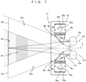
- Fig. 7 shows an outline configuration of an HMD 11 for AR (simply referred to as an HMD 11, unless otherwise confusing) according to a second embodiment.
- the HMD 11 includes a frame 12, display devices 13a and 13b for the left eye and the right eye, half mirrors 17a and 17b for the left eye and the right eye, virtual image forming optical systems 4a and 4b for the left eye and the right eye, wide-focus lenses 5a and 5b for the left eye and the right eye, and actuators 6a and 6b.
- components common to components of the HMD 1 according to the first embodiment are shown by using the same reference signs, and description thereof is omitted.
- the frame 12 is a housing that holds the display devices 13a and 13b for the left eye and the right eye and other components.
- the frame 12 holds the display devices 13a and 13b for the left eye and the right eye inside left and right side surfaces, opens the back surface to allow the inside to be viewed from the back surface side, and has a transparent front surface so that, when the inside is viewed from the back surface side, the front side can be viewed, and holds the half mirrors 17a and 17b for the left eye and the right eye on main visual lines La and Lb of the left eye Ea and the right eye Eb so as to allow display surfaces of the display devices 13a and 13b for the left eye and the right eye to be viewed.
- the virtual image forming optical systems 4a and 4b for the left eye and the right eye are held inside the frame 12 so that, in a state where a user wears the HMD 11, the main visual lines La and Lb of the left eye Ea and the right eye Eb, respectively bent through the half mirrors 17a and 17b for the left eye and the right eye, respectively overlap or substantially overlap the optical axes 4a 0 and 4b 0 of the virtual image forming optical systems 4a and 4b for the left eye and the right eye.
- the display devices 13a and 13b for the left eye and the right eye are devices to respectively display the images 3a and 3b for the left eye and the right eye on respective screens (also referred to as screens for the left eye and the right eye) of the display devices.
- the display devices 13a and 13b for example, flat panel displays such as liquid crystal displays and organic EL displays can be used.
- the display device 13a for the left eye is held inside the left side surface of the frame 12 so that its screen faces to the right.
- the display device 13b for the right eye is held inside the right side surface of the frame 12 so that its screen faces to the left.
- the half mirrors 17a and 17b for the left eye and the right eye are respectively optical members to realize a see-through function that superposes and projects the images 3a and 3b for the left eye and the right eye and light from a target object ahead onto the left eye Ea and the right eye Eb by respectively reflecting the images 3a and 3b for the left eye and the right eye displayed on the screens of the display devices 13a and 13b for the left eye and the right eye and transmitting the light from the target object ahead.
- the half mirror 17a for the left eye is disposed at a side opposite to the screen for the left eye (display device 13a for the left eye) of the virtual image forming optical system 4a for the left eye, ahead of the user's left eye Ea (that is, on the main visual line La).
- the half mirror 17b for the right eye is disposed at a side opposite to the screen for the right eye (display device 13b for the right eye) of the virtual image forming optical system 4b for the right eye, ahead of the user's right eye Ea (that is, on the main visual line Lb).
- the virtual image forming optical systems 4a and 4b for the left eye and the right eye are respectively disposed at the left side and the right side inside the frame 12 so as to face the screens of the display devices 13a and 13b for the left eye and the right eye, and form virtual images of the images 3a and 3b for the left eye and the right eye on virtual image display planes Va and Vb set ahead, and project magnified upright images of the virtual images on the left eye Ea and the right eye Eb.
- the virtual image on the virtual image display plane Va is viewed with the left eye Ea
- the virtual image on the virtual image display plane Vb is viewed with the right eye Eb
- virtual images can be stereoscopically viewed to be superposed with a target object actually present in this region. That is, a stereoscopic image superposed with a target object inside the region As is projected.
- the wide-focus lenses 5a and 5b for the left eye and the right eye are wide-focus lenses having a negative focal length with a range, and are respectively disposed with respect to the virtual image forming optical systems 4a and 4b for the left eye and the right eye so as to overlap optical axis directions of these optical systems. Accordingly, since focal lengths of the wide-focus lenses 5a and 5b for the left eye and the right eye have a range, virtual images of the images 3a and 3b for the left eye and the right eye formed by the virtual image forming optical systems 4a and 4b for the left eye and the right eye are displayed in a range with a width extending in the anteroposterior direction at the further side and/or nearer side than the virtual image display planes Va and Vb.
- focal lengths of the wide-focus lenses 5a and 5b for the left eye and the right eye can be determined in the same manner as in the HMD 1 according to the first embodiment. Accordingly, the virtual image forming range expands to the nearer side than the virtual image display planes Va and Vb, a range in which mismatch between vergence and accommodation is permitted expands to the near side, and comfortable stereovision in, for example, a working space that spreads in front of a user is enabled.
- the optical centers 5a 0 and 5b 0 of the wide-focus lenses 5a and 5b for the left eye and the right eye are disposed by being respectively shifted rearward with respect to the optical centers (that is, the optical axes 4a 0 and 4b 0 ) of the virtual image forming optical systems 4a and 4b for the left eye and the right eye, that is, toward the centerline L through the half-mirrors 17a and 17b for the left eye and the right eye.
- Each of the HMDs 1 and 11 includes the virtual image forming optical systems 4a and 4b for the left eye and the right eye and the wide-focus lenses 5a and 5b for the left eye and the right eye configured independently from each other, however, instead of these, each HMD may include, for each of the left eye and the right eye, an image forming system including at least one free-form surface lens designed so as to have both of the functions of the virtual image forming optical system and the wide-focus lens.
- a basic configuration of the HMD 21 is the same as that of the HMD 1 according to the first embodiment, and the HMD 21 is different from the HMD 1 in that a wide-focus lens 25 described below is used as the wide-focus lenses 5a and 5b for the left eye and the right eye.
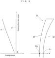
- the wide-focus lens 25 is a lens whose refractive power (power) at an optical center is 0 diopter, and average power gradually changes to the negative side from the optical center toward a lens peripheral edge portion.
- a focal length is expressed as a reciprocal of refractive power, so that the wide-focus lens 25 has a negative focal length with a range.
- Subjects are four in number (age of 30 to 55), and two of the four are spectacle wearers.
- Each subject viewed commercially available stereoscopic video content (3D movie) in a state where the subject wore stereoscopic glasses (refer to Fig. 5A ) including the wide-focus lenses of Examples.
- a distance between the display surface and the eyes of the subject was set to 90 to 120 cm.
- "viewability" and "eye fatigue” with the wide-focus lenses of Examples were evaluated according to 5 categories, bad, somewhat bad, unchanged, slightly better, and good, compared to the case where the glasses did not include the wide-focus lenses.
- Fig. 11 shows results (number of responses: 4) obtained after 30 minutes from the start of viewing of the movie.
- Fig. 12 shows results (number of responses: 3) obtained after 120 minutes from the viewing start.
- the HMD 21 of the present embodiment is configured by adding the first aspherical component expressed as Ar 4 +Br 6 +Cr 8 +Dr 10 and the second aspherical component expressed as Er 3 to the wide-focus lenses 5a and 5b for the left eye and the right eye respectively disposed with respect to the virtual image forming optical systems 4a and 4b for the left eye and the right eye so as to overlap the optical axis directions of the virtual image forming optical systems 4a and 4b for the left eye and the right eye.
- the wide-focus lens 25 by adding the first aspherical component expressed as Ar 4 +Br 6 +Cr 8 +Dr 10 in addition to the second aspherical component expressed as Er 3 to the wide-focus lens 25, a gradient of change in power can be maintained substantially constant in a wide range from the lens center to the lens peripheral edge portion, so that, even when a light beam group that enters the left eye Ea or the right eye Eb passes through a region near the lens peripheral edge portion of the wide-focus lenses 5a, 5b, the effect of the wide-focus lenses 5a, 5b on virtual image formation, that is, the effect of expanding the permissible range of vergence and accommodation, can be secured.
- execution sequences of the respective processes such as operations, procedures, steps, and stages, etc., in the devices, systems, programs, and methods shown in the claims, description, and drawings may be arbitrary sequences unless particular specifications such as “earlier than,” “prior to” are clearly given or an output of a previous process is used in a subsequent process. Even if operation flows in the claims, description, and drawings are described by using “first,” “next,” etc., for convenience, they do not mean that execution in the specified sequence is essential.
Landscapes
- Physics & Mathematics (AREA)
- General Physics & Mathematics (AREA)
- Optics & Photonics (AREA)
- Health & Medical Sciences (AREA)
- Ophthalmology & Optometry (AREA)
- General Health & Medical Sciences (AREA)
- Acoustics & Sound (AREA)
- Otolaryngology (AREA)
- Lenses (AREA)
Claims (7)
- Am Kopf montierte Anzeige (1; 11; 21), aufweisend:eine Anzeigevorrichtung (3; 13a, 13b) zur Anzeige von Bildern für das linke Auge (Ea) und das rechte Auge (Eb) auf einem Bildschirm (3c);optische Systeme (4a, 4b) zum Erzeugen virtueller Bilder für das linke Auge (Ea) und das rechte Auge (Eb), die jeweils in Bezug auf Bilder (3a, 3b) für das linke Auge (Ea) und das rechte Auge (Eb) auf dem Bildschirm (3c) angeordnet sind; undWeitwinkel-Linsen (5a, 5b; 25) für das linke Auge (Ea) und das rechte Auge (Eb), die eine negative Brennweite mit einem Bereich haben und jeweils in Bezug auf die optischen Systeme (4a, 4b) zum Erzeugen virtueller Bilder für das linke Auge (Ea) und das rechte Auge (Eb) so angeordnet sind, dass sie optische Achsenrichtungen der optischen Systeme (4a, 4b) zum Erzeugen virtueller Bilder für das linke Auge (Ea) und das rechte Auge (Eb) überlappen,wobei die Weitwinkel-Linsen (5a, 5b; 25) eine Brechkraft haben, deren Wert negativ und im Absolutwert minimal ist, wobei der Wert Null umfasst, am optischen Zentrum, undwobei die Brechkraft der Weitwinkel-Linsen (5a, 5b; 25) mit zunehmendem Abstand vom optischen Zentrum zunehmend negativ und im Absolutwert größer wird, so dass die negative Brennweite mit einem Bereich bereitgestellt wird.
- Am Kopf montierte Anzeige (1; 11; 21) nach Anspruch 1, wobei die optischen Zentren der Weitwinkel-Linsen (5a, 5b; 25) für das linke Auge (Ea) und das rechte Auge (Eb) angeordnet sind, indem sie jeweils zu einer Mittelseite zwischen den Linsen in einer Links-Rechts-Richtung in Bezug auf die optischen Zentren der optischen Systeme (4a, 4b) zum Erzeugen virtueller Bilder für das linke Auge (Ea) und das rechte Auge (Eb) versetzt sind.
- Am Kopf montierte Anzeige (1; 11; 21) nach Anspruch 2, wobei die Verschiebungsbeträge Δ der jeweiligen optischen Zentren der Weitwinkel-Linsen (5a, 5b; 25) für das linke Auge (Ea) und das rechte Auge (Eb) in Bezug auf optische Achsen von Linsen der optischen Systeme (4a, 4b) zum Erzeugen virtueller Bilder für das linke Auge (Ea) und das rechte Auge (Eb), um die sich die Weitwinkel-Linsen (5a, 5b; 25) überlappen, innerhalb eines Bereichs von Δ1 = Pd/2(I1+d) bis Δ2 = Pd/2(l2+d) in Bezug auf einen Abstand P zwischen den optischen Systemen (4a, 4b) zum Erzeugen virtueller Bilder für das linke Auge (Ea) und das rechte Auge (Eb) in der Links-Rechts-Richtung und einen Trennungsabstand d zwischen den Weitwinkel-Linsen (5a, 5b; 25) für das linke Auge (Ea) und das rechte Auge (Eb) und den Pupillen des linken Auges (Ea) und des rechten Auges (Eb) eines Benutzers liegen, wobei I1 = (1/I0 - 1/f1)-1 und I2 = (1/I0 - 1/f2)-1 ist, wobei I0 ein Trennungsabstand zwischen den Weitwinkel-Linsen (5a, 5b; 25) für das linke Auge (Ea) und das rechte Auge (Eb) und virtuellen Bildanzeigeebenen (Va, Vb) ist, die durch die optischen Systeme (4a, 4b) zum Erzeugen virtueller Bilder für das linke Auge (Ea) und das rechte Auge (Eb) gebildet werden, und f1 bis f2 der Bereich der Brennweiten der Weitwinkel-Linsen (5a, 5b; 25) für das linke Auge (Ea) und das rechte Auge (Eb) sind.
- Am Kopf montierte Anzeige (1; 11; 21) nach Anspruch 3, ferner aufweisend: Verschiebungsmechanismen (6a, 6b), um die Weitwinkel-Linsen (5a, 5b; 25) für das linke Auge (Ea) und das rechte Auge (Eb) jeweils in der Links-Rechts-Richtung in Bezug auf die optischen Systeme (4a, 4b) zum Erzeugen virtueller Bilder für das linke Auge (Ea) und das rechte Auge (Eb) zu verschieben.
- Am Kopf montierte Anzeige (11) nach einem der Ansprüche 1 bis 4, wobeidie Anzeigevorrichtung (13a, 13b) Bildschirme für das linke Auge (Ea) und das rechte Auge (Eb) aufweist, um jeweils die Bilder (3a, 3b) für das linke Auge (Ea) und das rechte Auge (Eb) anzuzeigen, undwobei die am Kopf montierte Anzeige (1) ferner aufweist:einen Halbspiegel (17a) für das linke Auge (Ea), der an einer dem Bildschirm für das linke Auge (Ea) gegenüberliegenden Seite des optischen Systems (4a) zum Erzeugen virtueller Bilder für das linke Auge (Ea) vor dem linken Auge (Ea) des Benutzers angeordnet ist; undeinen Halbspiegel (17b) für das rechte Auge (Eb), der an einer Seite gegenüber dem Bildschirm für das rechte Auge (Eb) des optischen Systems (4b) zum Erzeugen virtueller Bilder für das rechte Auge (Eb) vor dem rechten Auge (Eb) des Benutzers angeordnet ist.
- Am Kopf montierte Anzeige (21) nach Anspruch 1, wobeiwenn eine Achse in der anteroposterioren Richtung, die durch ein optisches Zentrum einer Weitwinkel-Linse (25) verläuft, die als Weitwinkel-Linsen (25) für das linke Auge (Ea) und das rechte Auge (Eb) verwendet werden soll, als eine z-Achse definiert ist, und eine Richtung zur Rückseite der Linse (25) als eine positive Richtung der z-Achse definiert ist, wird eine erste asphärische Komponente (δ1), die als Ar4+Br6+Cr8+Dr10 ausgedrückt werden kann (r ist ein Abstand von der z-Achse, und A, B, C und D sind Konstanten) und die Fluktuation der durchschnittlichen Stärke von der optischen Mitte zu einem Randbereich der Linse unterdrückt, zu einem z-Koordinatenwert der vorderen Fläche (53) und/oder der hinteren Fläche (52) der Linse (25) addiert, undeine zweite asphärische Komponente (δ2), die als Er3 ausgedrückt werden kann (E ist eine Konstante), wird zu einem z-Koordinatenwert der vorderen Fläche (53) oder der hinteren Fläche (52) der Linse (25) addiert.
- Am Kopf montierte Anzeige (1; 11; 21) nach Anspruch 1, wobei die Weitwinkel-Linsen (5a, 5b; 25) integral mit den optischen Systemen (4a, 4b) zur virtuellen Bilderzeugung konfiguriert sind.
Applications Claiming Priority (3)
| Application Number | Priority Date | Filing Date | Title |
|---|---|---|---|
| JP2018194640 | 2018-10-15 | ||
| JP2019001404 | 2019-01-08 | ||
| PCT/JP2019/028635 WO2020079906A1 (ja) | 2018-10-15 | 2019-07-22 | ヘッドマウントディスプレイおよびこれに用いられる広焦点レンズの設計方法 |
Publications (4)
| Publication Number | Publication Date |
|---|---|
| EP3663835A1 EP3663835A1 (de) | 2020-06-10 |
| EP3663835A4 EP3663835A4 (de) | 2021-06-23 |
| EP3663835C0 EP3663835C0 (de) | 2025-07-09 |
| EP3663835B1 true EP3663835B1 (de) | 2025-07-09 |
Family
ID=70283863
Family Applications (1)
| Application Number | Title | Priority Date | Filing Date |
|---|---|---|---|
| EP19805873.7A Active EP3663835B1 (de) | 2018-10-15 | 2019-07-22 | Am kopf montierte anzeige und verfahren zum entwurf einer weitfokuslinse für die am kopf montierte anzeige |
Country Status (5)
| Country | Link |
|---|---|
| US (1) | US11740459B2 (de) |
| EP (1) | EP3663835B1 (de) |
| JP (1) | JP7533858B2 (de) |
| CN (1) | CN111328380B (de) |
| WO (1) | WO2020079906A1 (de) |
Families Citing this family (7)
| Publication number | Priority date | Publication date | Assignee | Title |
|---|---|---|---|---|
| WO2020011349A1 (en) * | 2018-07-11 | 2020-01-16 | Huawei Technologies Co., Ltd. | A detachable optical structure for displacing the optical axis of a camera device |
| CN114185169B (zh) * | 2020-08-25 | 2024-03-05 | 成都理想境界科技有限公司 | 一种散射屏参数优化方法、散射屏及可读存储介质 |
| CN112068326B (zh) * | 2020-09-17 | 2022-08-09 | 京东方科技集团股份有限公司 | 3d显示装置 |
| CN112255789B (zh) * | 2020-10-21 | 2022-04-22 | 京东方科技集团股份有限公司 | 虚拟现实显示光学系统及虚拟现实设备 |
| CN113671607B (zh) * | 2020-12-14 | 2022-10-25 | 明月镜片股份有限公司 | 一种双面非球面镜片及其设计方法 |
| CN115128802B (zh) | 2021-03-24 | 2025-09-23 | 群创光电股份有限公司 | 影像的显示方法 |
| EP4382995A4 (de) * | 2021-08-20 | 2024-12-04 | Sony Group Corporation | Anzeigevorrichtung und anzeigeverfahren |
Citations (1)
| Publication number | Priority date | Publication date | Assignee | Title |
|---|---|---|---|---|
| US20120250152A1 (en) * | 2011-03-31 | 2012-10-04 | Honeywell International Inc. | Variable focus stereoscopic display system and method |
Family Cites Families (20)
| Publication number | Priority date | Publication date | Assignee | Title |
|---|---|---|---|---|
| US4577942A (en) * | 1983-02-22 | 1986-03-25 | Optical Systems International, Inc. | Laminated high correction eyeglass lens |
| JP3556389B2 (ja) | 1996-05-01 | 2004-08-18 | 日本電信電話株式会社 | ヘッドマウントディスプレイ装置 |
| JPH10282448A (ja) | 1997-04-04 | 1998-10-23 | Minolta Co Ltd | ディスプレイ |
| JP2002031776A (ja) | 2000-07-14 | 2002-01-31 | Canon Inc | 表示装置 |
| JP2003241081A (ja) * | 2002-02-20 | 2003-08-27 | Fuji Photo Optical Co Ltd | 全長の短い単焦点レンズ |
| JP2005227682A (ja) | 2004-02-16 | 2005-08-25 | Victor Co Of Japan Ltd | 立体画像表示装置 |
| EP2577388A1 (de) * | 2010-06-01 | 2013-04-10 | Elenza, Inc. | Implantierbare augenvorrichtung mit einer nicht kugelförmigen linse |
| US9734622B2 (en) * | 2010-06-01 | 2017-08-15 | Vladimir Vaganov | 3D digital painting |
| JP2012078670A (ja) | 2010-10-04 | 2012-04-19 | Hoya Corp | 立体映像観察用眼鏡 |
| US9703103B2 (en) | 2014-03-14 | 2017-07-11 | Sony Corporation | Head-mounted display |
| WO2015195549A1 (en) | 2014-06-16 | 2015-12-23 | Vladimir Vaganov | 3d digital painting |
| JP6294780B2 (ja) * | 2014-07-17 | 2018-03-14 | 株式会社ソニー・インタラクティブエンタテインメント | 立体画像提示装置、立体画像提示方法、およびヘッドマウントディスプレイ |
| TW201617690A (zh) | 2014-08-13 | 2016-05-16 | 阿爾發普瑞米特斯股份有限公司 | 用於智慧型眼用佩戴品之處方鏡片 |
| US9681804B2 (en) | 2015-01-12 | 2017-06-20 | X Development Llc | Hybrid lens system for head wearable display |
| JP6374345B2 (ja) | 2015-04-20 | 2018-08-15 | 伊藤光学工業株式会社 | 視力矯正用レンズの設計方法及び視力矯正用レンズ |
| TWI569040B (zh) | 2015-05-07 | 2017-02-01 | 尚立光電股份有限公司 | 自動調焦頭戴式顯示裝置 |
| SG11201800595QA (en) * | 2015-07-24 | 2018-02-27 | Eyebright Medical Tech Beijing Co Ltd | Vision correction lens and method for preparation of the same |
| CN106353892B (zh) | 2015-07-24 | 2020-02-07 | 爱博诺德(北京)医疗科技股份有限公司 | 一种眼内镜 |
| US11131868B2 (en) * | 2016-11-25 | 2021-09-28 | Itoh Optical Industrial Co., Ltd. | Method for corrective lens and corrective lens |
| CN109725418B (zh) * | 2017-10-30 | 2020-10-16 | 华为技术有限公司 | 显示设备、用于调整显示设备的图像呈现的方法及装置 |
-
2019
- 2019-07-22 US US16/617,689 patent/US11740459B2/en active Active
- 2019-07-22 EP EP19805873.7A patent/EP3663835B1/de active Active
- 2019-07-22 WO PCT/JP2019/028635 patent/WO2020079906A1/ja not_active Ceased
- 2019-07-22 JP JP2020502732A patent/JP7533858B2/ja active Active
- 2019-07-22 CN CN201980002658.7A patent/CN111328380B/zh active Active
Patent Citations (1)
| Publication number | Priority date | Publication date | Assignee | Title |
|---|---|---|---|---|
| US20120250152A1 (en) * | 2011-03-31 | 2012-10-04 | Honeywell International Inc. | Variable focus stereoscopic display system and method |
Also Published As
| Publication number | Publication date |
|---|---|
| CN111328380A (zh) | 2020-06-23 |
| WO2020079906A1 (ja) | 2020-04-23 |
| EP3663835C0 (de) | 2025-07-09 |
| JPWO2020079906A1 (ja) | 2021-09-02 |
| JP7533858B2 (ja) | 2024-08-14 |
| CN111328380B (zh) | 2023-04-04 |
| EP3663835A4 (de) | 2021-06-23 |
| US11740459B2 (en) | 2023-08-29 |
| EP3663835A1 (de) | 2020-06-10 |
| US20210286177A1 (en) | 2021-09-16 |
Similar Documents
| Publication | Publication Date | Title |
|---|---|---|
| EP3663835B1 (de) | Am kopf montierte anzeige und verfahren zum entwurf einer weitfokuslinse für die am kopf montierte anzeige | |
| US11221494B2 (en) | Adaptive viewport optical display systems and methods | |
| CN110637249B (zh) | 光学设备、头戴式显示器、成像系统和对对象成像的方法 | |
| EP0509090B1 (de) | Auf dem kopf getragene videoanzeigevorrichtung | |
| JP5290092B2 (ja) | 眼鏡型画像表示装置 | |
| CN109073897B (zh) | 用于为电子信息装置提供显示装置的方法 | |
| JP6675318B2 (ja) | 補助画像を出力するように構成された多焦点眼鏡レンズ | |
| US11300805B2 (en) | Stereoscopic eyeglasses, method for designing eyeglass lens to be used for the stereoscopic eyeglasses, and method for observing stereoscopic image | |
| JP2022509114A (ja) | 近焦点の矯正ar眼鏡 | |
| KR101632156B1 (ko) | 초근거리를 볼 수 있는 교정렌즈 | |
| JP6495005B2 (ja) | 両眼用の一対の眼鏡レンズ、その製造方法、供給システム、および供給プログラム | |
| WO2020123526A1 (en) | Optical system for ar headsets, and method for design and manufacturing | |
| CN113341567A (zh) | 一种双焦面光波导近眼显示光学系统 | |
| Stevens et al. | Varifocal technologies providing prescription and VAC mitigation in HMDs using Alvarez lenses | |
| JP2020024363A (ja) | 表示装置 | |
| KR101490778B1 (ko) | 초 근거리를 볼 수 있는 교정 렌즈 및 그 장치 | |
| CN115004084B (zh) | 头戴式显示器以及在该头戴式显示器中使用的虚像成像透镜 | |
| US20240393582A1 (en) | Vision correction for near eye display | |
| WO2020026749A1 (ja) | 表示装置 | |
| WO2012132959A1 (ja) | 視覚表示装置 | |
| KR20250168636A (ko) | 근안 디스플레이를 위한 시력 보정 | |
| KR101632140B1 (ko) | 초근거리를 볼 수 있는 교정 렌즈 어셈블리 | |
| JP2004029223A (ja) | 眼鏡レンズ製造方法及び装置 | |
| HK1154080A (en) | Spectacles-type image display device |
Legal Events
| Date | Code | Title | Description |
|---|---|---|---|
| STAA | Information on the status of an ep patent application or granted ep patent |
Free format text: STATUS: UNKNOWN |
|
| STAA | Information on the status of an ep patent application or granted ep patent |
Free format text: STATUS: THE INTERNATIONAL PUBLICATION HAS BEEN MADE |
|
| PUAI | Public reference made under article 153(3) epc to a published international application that has entered the european phase |
Free format text: ORIGINAL CODE: 0009012 |
|
| STAA | Information on the status of an ep patent application or granted ep patent |
Free format text: STATUS: REQUEST FOR EXAMINATION WAS MADE |
|
| 17P | Request for examination filed |
Effective date: 20191128 |
|
| AK | Designated contracting states |
Kind code of ref document: A1 Designated state(s): AL AT BE BG CH CY CZ DE DK EE ES FI FR GB GR HR HU IE IS IT LI LT LU LV MC MK MT NL NO PL PT RO RS SE SI SK SM TR |
|
| AX | Request for extension of the european patent |
Extension state: BA ME |
|
| RIN1 | Information on inventor provided before grant (corrected) |
Inventor name: TAKAKI, YASUHIRO Inventor name: MIYAJIMA, YASUSHI |
|
| RAP1 | Party data changed (applicant data changed or rights of an application transferred) |
Owner name: NATIONAL UNIVERSITY CORPORATION TOKYO UNIVERSITY OF AGRICULTURE AND TECHNOLOGY Owner name: ITOH OPTICAL INDUSTRIAL CO., LTD. |
|
| A4 | Supplementary search report drawn up and despatched |
Effective date: 20210525 |
|
| RIC1 | Information provided on ipc code assigned before grant |
Ipc: G02B 27/02 20060101AFI20210518BHEP Ipc: G02B 13/16 20060101ALI20210518BHEP Ipc: G02B 17/08 20060101ALI20210518BHEP Ipc: G02B 25/00 20060101ALI20210518BHEP Ipc: G02B 30/22 20200101ALI20210518BHEP Ipc: G03B 35/20 20210101ALI20210518BHEP Ipc: H04N 13/339 20180101ALI20210518BHEP Ipc: H04N 13/344 20180101ALI20210518BHEP Ipc: H04N 13/346 20180101ALI20210518BHEP Ipc: G02B 27/01 20060101ALI20210518BHEP Ipc: G02B 27/00 20060101ALI20210518BHEP |
|
| DAV | Request for validation of the european patent (deleted) | ||
| DAX | Request for extension of the european patent (deleted) | ||
| STAA | Information on the status of an ep patent application or granted ep patent |
Free format text: STATUS: EXAMINATION IS IN PROGRESS |
|
| 17Q | First examination report despatched |
Effective date: 20230223 |
|
| GRAP | Despatch of communication of intention to grant a patent |
Free format text: ORIGINAL CODE: EPIDOSNIGR1 |
|
| STAA | Information on the status of an ep patent application or granted ep patent |
Free format text: STATUS: GRANT OF PATENT IS INTENDED |
|
| INTG | Intention to grant announced |
Effective date: 20250203 |
|
| GRAS | Grant fee paid |
Free format text: ORIGINAL CODE: EPIDOSNIGR3 |
|
| GRAA | (expected) grant |
Free format text: ORIGINAL CODE: 0009210 |
|
| STAA | Information on the status of an ep patent application or granted ep patent |
Free format text: STATUS: THE PATENT HAS BEEN GRANTED |
|
| AK | Designated contracting states |
Kind code of ref document: B1 Designated state(s): AL AT BE BG CH CY CZ DE DK EE ES FI FR GB GR HR HU IE IS IT LI LT LU LV MC MK MT NL NO PL PT RO RS SE SI SK SM TR |
|
| REG | Reference to a national code |
Ref country code: GB Ref legal event code: FG4D |
|
| REG | Reference to a national code |
Ref country code: CH Ref legal event code: EP |
|
| REG | Reference to a national code |
Ref country code: IE Ref legal event code: FG4D |
|
| REG | Reference to a national code |
Ref country code: DE Ref legal event code: R096 Ref document number: 602019072350 Country of ref document: DE |
|
| U01 | Request for unitary effect filed |
Effective date: 20250717 |
|
| U07 | Unitary effect registered |
Designated state(s): AT BE BG DE DK EE FI FR IT LT LU LV MT NL PT RO SE SI Effective date: 20250725 |
|
| U20 | Renewal fee for the european patent with unitary effect paid |
Year of fee payment: 7 Effective date: 20250724 |