EP3663567A1 - Garden tool - Google Patents
Garden tool Download PDFInfo
- Publication number
- EP3663567A1 EP3663567A1 EP20153836.0A EP20153836A EP3663567A1 EP 3663567 A1 EP3663567 A1 EP 3663567A1 EP 20153836 A EP20153836 A EP 20153836A EP 3663567 A1 EP3663567 A1 EP 3663567A1
- Authority
- EP
- European Patent Office
- Prior art keywords
- gasoline engine
- garden tool
- disposed
- controller
- speed reduction
- Prior art date
- Legal status (The legal status is an assumption and is not a legal conclusion. Google has not performed a legal analysis and makes no representation as to the accuracy of the status listed.)
- Withdrawn
Links
- 239000003502 gasoline Substances 0.000 claims abstract description 107
- 239000000446 fuel Substances 0.000 claims abstract description 93
- HBBGRARXTFLTSG-UHFFFAOYSA-N Lithium ion Chemical compound [Li+] HBBGRARXTFLTSG-UHFFFAOYSA-N 0.000 claims abstract description 28
- 229910001416 lithium ion Inorganic materials 0.000 claims abstract description 28
- 230000009467 reduction Effects 0.000 claims description 40
- 239000007858 starting material Substances 0.000 claims description 38
- 230000005540 biological transmission Effects 0.000 claims description 24
- 230000033001 locomotion Effects 0.000 claims description 17
- 238000004146 energy storage Methods 0.000 claims description 16
- 230000011664 signaling Effects 0.000 abstract description 9
- 244000025254 Cannabis sativa Species 0.000 description 34
- 238000010586 diagram Methods 0.000 description 16
- 230000001276 controlling effect Effects 0.000 description 10
- 238000004891 communication Methods 0.000 description 7
- 230000001939 inductive effect Effects 0.000 description 6
- 238000002485 combustion reaction Methods 0.000 description 5
- 238000002347 injection Methods 0.000 description 4
- 239000007924 injection Substances 0.000 description 4
- 238000000034 method Methods 0.000 description 4
- 239000000203 mixture Substances 0.000 description 4
- 230000013011 mating Effects 0.000 description 3
- 230000008569 process Effects 0.000 description 3
- 239000000243 solution Substances 0.000 description 3
- 238000010892 electric spark Methods 0.000 description 2
- 230000001976 improved effect Effects 0.000 description 2
- 238000009434 installation Methods 0.000 description 2
- 230000003213 activating effect Effects 0.000 description 1
- 230000009286 beneficial effect Effects 0.000 description 1
- 238000004364 calculation method Methods 0.000 description 1
- 230000000694 effects Effects 0.000 description 1
- 238000005516 engineering process Methods 0.000 description 1
- 210000003811 finger Anatomy 0.000 description 1
- 239000002828 fuel tank Substances 0.000 description 1
- 230000003993 interaction Effects 0.000 description 1
- 230000007257 malfunction Effects 0.000 description 1
- 238000005259 measurement Methods 0.000 description 1
- 238000012986 modification Methods 0.000 description 1
- 230000004048 modification Effects 0.000 description 1
- 230000002035 prolonged effect Effects 0.000 description 1
- 230000001105 regulatory effect Effects 0.000 description 1
- 210000003813 thumb Anatomy 0.000 description 1
- 230000001960 triggered effect Effects 0.000 description 1
Images


Classifications
-
- F—MECHANICAL ENGINEERING; LIGHTING; HEATING; WEAPONS; BLASTING
- F02—COMBUSTION ENGINES; HOT-GAS OR COMBUSTION-PRODUCT ENGINE PLANTS
- F02D—CONTROLLING COMBUSTION ENGINES
- F02D41/00—Electrical control of supply of combustible mixture or its constituents
- F02D41/0025—Controlling engines characterised by use of non-liquid fuels, pluralities of fuels, or non-fuel substances added to the combustible mixtures
-
- F—MECHANICAL ENGINEERING; LIGHTING; HEATING; WEAPONS; BLASTING
- F02—COMBUSTION ENGINES; HOT-GAS OR COMBUSTION-PRODUCT ENGINE PLANTS
- F02D—CONTROLLING COMBUSTION ENGINES
- F02D9/00—Controlling engines by throttling air or fuel-and-air induction conduits or exhaust conduits
- F02D9/02—Controlling engines by throttling air or fuel-and-air induction conduits or exhaust conduits concerning induction conduits
-
- A—HUMAN NECESSITIES
- A01—AGRICULTURE; FORESTRY; ANIMAL HUSBANDRY; HUNTING; TRAPPING; FISHING
- A01D—HARVESTING; MOWING
- A01D34/00—Mowers; Mowing apparatus of harvesters
- A01D34/01—Mowers; Mowing apparatus of harvesters characterised by features relating to the type of cutting apparatus
- A01D34/412—Mowers; Mowing apparatus of harvesters characterised by features relating to the type of cutting apparatus having rotating cutters
- A01D34/416—Flexible line cutters
-
- A—HUMAN NECESSITIES
- A01—AGRICULTURE; FORESTRY; ANIMAL HUSBANDRY; HUNTING; TRAPPING; FISHING
- A01D—HARVESTING; MOWING
- A01D69/00—Driving mechanisms or parts thereof for harvesters or mowers
-
- F—MECHANICAL ENGINEERING; LIGHTING; HEATING; WEAPONS; BLASTING
- F02—COMBUSTION ENGINES; HOT-GAS OR COMBUSTION-PRODUCT ENGINE PLANTS
- F02D—CONTROLLING COMBUSTION ENGINES
- F02D11/00—Arrangements for, or adaptations to, non-automatic engine control initiation means, e.g. operator initiated
- F02D11/02—Arrangements for, or adaptations to, non-automatic engine control initiation means, e.g. operator initiated characterised by hand, foot, or like operator controlled initiation means
-
- F—MECHANICAL ENGINEERING; LIGHTING; HEATING; WEAPONS; BLASTING
- F02—COMBUSTION ENGINES; HOT-GAS OR COMBUSTION-PRODUCT ENGINE PLANTS
- F02D—CONTROLLING COMBUSTION ENGINES
- F02D11/00—Arrangements for, or adaptations to, non-automatic engine control initiation means, e.g. operator initiated
- F02D11/06—Arrangements for, or adaptations to, non-automatic engine control initiation means, e.g. operator initiated characterised by non-mechanical control linkages, e.g. fluid control linkages or by control linkages with power drive or assistance
- F02D11/10—Arrangements for, or adaptations to, non-automatic engine control initiation means, e.g. operator initiated characterised by non-mechanical control linkages, e.g. fluid control linkages or by control linkages with power drive or assistance of the electric type
-
- F—MECHANICAL ENGINEERING; LIGHTING; HEATING; WEAPONS; BLASTING
- F02—COMBUSTION ENGINES; HOT-GAS OR COMBUSTION-PRODUCT ENGINE PLANTS
- F02D—CONTROLLING COMBUSTION ENGINES
- F02D33/00—Controlling delivery of fuel or combustion-air, not otherwise provided for
- F02D33/003—Controlling the feeding of liquid fuel from storage containers to carburettors or fuel-injection apparatus ; Failure or leakage prevention; Diagnosis or detection of failure; Arrangement of sensors in the fuel system; Electric wiring; Electrostatic discharge
- F02D33/006—Controlling the feeding of liquid fuel from storage containers to carburettors or fuel-injection apparatus ; Failure or leakage prevention; Diagnosis or detection of failure; Arrangement of sensors in the fuel system; Electric wiring; Electrostatic discharge depending on engine operating conditions, e.g. start, stop or ambient conditions
-
- F—MECHANICAL ENGINEERING; LIGHTING; HEATING; WEAPONS; BLASTING
- F02—COMBUSTION ENGINES; HOT-GAS OR COMBUSTION-PRODUCT ENGINE PLANTS
- F02D—CONTROLLING COMBUSTION ENGINES
- F02D35/00—Controlling engines, dependent on conditions exterior or interior to engines, not otherwise provided for
- F02D35/0015—Controlling engines, dependent on conditions exterior or interior to engines, not otherwise provided for using exhaust gas sensors
- F02D35/0046—Controlling fuel supply
- F02D35/0053—Controlling fuel supply by means of a carburettor
-
- F—MECHANICAL ENGINEERING; LIGHTING; HEATING; WEAPONS; BLASTING
- F02—COMBUSTION ENGINES; HOT-GAS OR COMBUSTION-PRODUCT ENGINE PLANTS
- F02M—SUPPLYING COMBUSTION ENGINES IN GENERAL WITH COMBUSTIBLE MIXTURES OR CONSTITUENTS THEREOF
- F02M1/00—Carburettors with means for facilitating engine's starting or its idling below operational temperatures
- F02M1/02—Carburettors with means for facilitating engine's starting or its idling below operational temperatures the means to facilitate starting or idling being chokes for enriching fuel-air mixture
-
- F—MECHANICAL ENGINEERING; LIGHTING; HEATING; WEAPONS; BLASTING
- F02—COMBUSTION ENGINES; HOT-GAS OR COMBUSTION-PRODUCT ENGINE PLANTS
- F02M—SUPPLYING COMBUSTION ENGINES IN GENERAL WITH COMBUSTIBLE MIXTURES OR CONSTITUENTS THEREOF
- F02M1/00—Carburettors with means for facilitating engine's starting or its idling below operational temperatures
- F02M1/08—Carburettors with means for facilitating engine's starting or its idling below operational temperatures the means to facilitate starting or idling becoming operative or inoperative automatically
-
- F—MECHANICAL ENGINEERING; LIGHTING; HEATING; WEAPONS; BLASTING
- F02—COMBUSTION ENGINES; HOT-GAS OR COMBUSTION-PRODUCT ENGINE PLANTS
- F02M—SUPPLYING COMBUSTION ENGINES IN GENERAL WITH COMBUSTIBLE MIXTURES OR CONSTITUENTS THEREOF
- F02M1/00—Carburettors with means for facilitating engine's starting or its idling below operational temperatures
- F02M1/16—Other means for enriching fuel-air mixture during starting; Priming cups; using different fuels for starting and normal operation
-
- F—MECHANICAL ENGINEERING; LIGHTING; HEATING; WEAPONS; BLASTING
- F02—COMBUSTION ENGINES; HOT-GAS OR COMBUSTION-PRODUCT ENGINE PLANTS
- F02N—STARTING OF COMBUSTION ENGINES; STARTING AIDS FOR SUCH ENGINES, NOT OTHERWISE PROVIDED FOR
- F02N11/00—Starting of engines by means of electric motors
- F02N11/08—Circuits or control means specially adapted for starting of engines
-
- A—HUMAN NECESSITIES
- A01—AGRICULTURE; FORESTRY; ANIMAL HUSBANDRY; HUNTING; TRAPPING; FISHING
- A01D—HARVESTING; MOWING
- A01D2101/00—Lawn-mowers
-
- F—MECHANICAL ENGINEERING; LIGHTING; HEATING; WEAPONS; BLASTING
- F02—COMBUSTION ENGINES; HOT-GAS OR COMBUSTION-PRODUCT ENGINE PLANTS
- F02B—INTERNAL-COMBUSTION PISTON ENGINES; COMBUSTION ENGINES IN GENERAL
- F02B63/00—Adaptations of engines for driving pumps, hand-held tools or electric generators; Portable combinations of engines with engine-driven devices
- F02B63/02—Adaptations of engines for driving pumps, hand-held tools or electric generators; Portable combinations of engines with engine-driven devices for hand-held tools
-
- F—MECHANICAL ENGINEERING; LIGHTING; HEATING; WEAPONS; BLASTING
- F02—COMBUSTION ENGINES; HOT-GAS OR COMBUSTION-PRODUCT ENGINE PLANTS
- F02D—CONTROLLING COMBUSTION ENGINES
- F02D9/00—Controlling engines by throttling air or fuel-and-air induction conduits or exhaust conduits
- F02D9/02—Controlling engines by throttling air or fuel-and-air induction conduits or exhaust conduits concerning induction conduits
- F02D2009/0201—Arrangements; Control features; Details thereof
- F02D2009/0205—Arrangements; Control features; Details thereof working on the throttle valve and another valve, e.g. choke
-
- F—MECHANICAL ENGINEERING; LIGHTING; HEATING; WEAPONS; BLASTING
- F02—COMBUSTION ENGINES; HOT-GAS OR COMBUSTION-PRODUCT ENGINE PLANTS
- F02D—CONTROLLING COMBUSTION ENGINES
- F02D9/00—Controlling engines by throttling air or fuel-and-air induction conduits or exhaust conduits
- F02D9/02—Controlling engines by throttling air or fuel-and-air induction conduits or exhaust conduits concerning induction conduits
- F02D2009/0201—Arrangements; Control features; Details thereof
- F02D2009/0225—Intake air or mixture temperature
-
- F—MECHANICAL ENGINEERING; LIGHTING; HEATING; WEAPONS; BLASTING
- F02—COMBUSTION ENGINES; HOT-GAS OR COMBUSTION-PRODUCT ENGINE PLANTS
- F02D—CONTROLLING COMBUSTION ENGINES
- F02D11/00—Arrangements for, or adaptations to, non-automatic engine control initiation means, e.g. operator initiated
- F02D11/06—Arrangements for, or adaptations to, non-automatic engine control initiation means, e.g. operator initiated characterised by non-mechanical control linkages, e.g. fluid control linkages or by control linkages with power drive or assistance
- F02D11/10—Arrangements for, or adaptations to, non-automatic engine control initiation means, e.g. operator initiated characterised by non-mechanical control linkages, e.g. fluid control linkages or by control linkages with power drive or assistance of the electric type
- F02D2011/101—Arrangements for, or adaptations to, non-automatic engine control initiation means, e.g. operator initiated characterised by non-mechanical control linkages, e.g. fluid control linkages or by control linkages with power drive or assistance of the electric type characterised by the means for actuating the throttles
-
- F—MECHANICAL ENGINEERING; LIGHTING; HEATING; WEAPONS; BLASTING
- F02—COMBUSTION ENGINES; HOT-GAS OR COMBUSTION-PRODUCT ENGINE PLANTS
- F02D—CONTROLLING COMBUSTION ENGINES
- F02D2200/00—Input parameters for engine control
- F02D2200/02—Input parameters for engine control the parameters being related to the engine
- F02D2200/04—Engine intake system parameters
- F02D2200/0414—Air temperature
-
- F—MECHANICAL ENGINEERING; LIGHTING; HEATING; WEAPONS; BLASTING
- F02—COMBUSTION ENGINES; HOT-GAS OR COMBUSTION-PRODUCT ENGINE PLANTS
- F02D—CONTROLLING COMBUSTION ENGINES
- F02D2400/00—Control systems adapted for specific engine types; Special features of engine control systems not otherwise provided for; Power supply, connectors or cabling for engine control systems
- F02D2400/06—Small engines with electronic control, e.g. for hand held tools
-
- F—MECHANICAL ENGINEERING; LIGHTING; HEATING; WEAPONS; BLASTING
- F02—COMBUSTION ENGINES; HOT-GAS OR COMBUSTION-PRODUCT ENGINE PLANTS
- F02D—CONTROLLING COMBUSTION ENGINES
- F02D41/00—Electrical control of supply of combustible mixture or its constituents
- F02D41/0002—Controlling intake air
-
- F—MECHANICAL ENGINEERING; LIGHTING; HEATING; WEAPONS; BLASTING
- F02—COMBUSTION ENGINES; HOT-GAS OR COMBUSTION-PRODUCT ENGINE PLANTS
- F02D—CONTROLLING COMBUSTION ENGINES
- F02D41/00—Electrical control of supply of combustible mixture or its constituents
- F02D41/30—Controlling fuel injection
- F02D41/3005—Details not otherwise provided for
Definitions
- Embodiments of the present invention relate to a garden tool, especially relate to a garden tool using a gasoline engine as a power source.
- garden tools can be divided into electric garden tools and internal combustion engine garden tools.
- gasoline engine garden tools are mostly used.
- the gasoline engine garden tools are mainly manually controlled by users' operations. For example, when a gasoline engine is cold started, since the gasoline engine is in a low temperature state, a user is required to manually draw a starter rope to run a crankshaft of the gasoline engine, and cooperatively control opening and closing of a fuel throttle and a choker of the gasoline engine at the same time. This is very demanding for users' operation skills, or there may be faults like misfire occurring with the gasoline engine.
- a starter motor has been used to instead the starter rope, the fuel throttle and the choker of the gasoline engine are still hard to be cooperatively controlled.
- a currently widely used ignition system includes a magneto, an ignitor, and a magnet mounted on a flywheel. Ignition voltage is generated by the interaction of the magnet and the magneto, and causes the ignitor to operate.
- the ignition system has following disadvantages: since ignition voltage is proportional to a rotational speed of the flywheel, when the rotational speed is relatively low, ignition power is also relatively low. Especially in the engine starting phase, due to the low rotational speed, the ignition power cannot generate a large spark required. As a result, the garden tools are difficult to be started and the users' experience is affected.
- the garden tools may not always be maintained in the best working condition.
- a starter motor When a user lacks operation experiences and skills, malfunctions are easily to be caused.
- garden tools equipped with a starter motor are usually equipped with a battery pack to power the starter motor.
- the starter motor does not have to work during normal working of the garden tools, thus the battery pack is also idle during normal working of the garden tools. It can be seen that the battery pack actually adds product cost.
- Embodiments of the present invention are directed to providing a gasoline engine garden tool, which can be controlled easily and conveniently through a single controller.
- a garden tool including a gasoline engine, the gasoline engine including an engine block, a fuel supply system disposed in the engine block and an ignition system disposed in the engine block; wherein the garden tool further includes a control system, the control system including at least one sensor used for collecting a working condition signal of the gasoline engine and a single controller used for receiving the working condition signal and controlling the fuel supply system and/or the ignition system according to the working condition signals received.
- the control system includes a first sensor used for measuring a first ambient temperature signal, and the controller adjusts a fuel supply amount and an air-fuel ratio according to the first ambient temperature signal; wherein the fuel supply system includes a carburetor and an automatic choke control unit, the carburetor includes an intake passage, the automatic choke control unit includes a choke valve used for at least partially closing the intake passage and a choke actuator used for driving movement of the choke valve, and the controller controls the movement of the choke valve through the choke actuator so as to control an air amount throughout the carburetor; wherein the fuel supply system further includes an automatic fuel throttle control unit, the carburetor includes an intake passage, the automatic fuel throttle control unit includes a throttle used for at least partially closing the intake passage and a throttle actuator used for driving movement of the throttle, and the controller controls the movement of the throttle through the throttle actuator so as to control a fuel amount throughout the carburetor.
- the fuel supply system includes a carburetor and an automatic choke control unit, the carburetor includes an intake passage, the automatic fuel throttle control unit
- the fuel supply system includes an electric fuel injector
- the control system includes a first sensor used for measuring a first ambient temperature signal
- the controller adjusts a fuel injection amount and an air-fuel ratio according to the first ambient temperature signal.
- control system includes a second sensor used for measuring a rotational speed signal of the gasoline engine and a third sensor used for measuring a second ambient temperature signal, the controller adjusts ignition voltage and/or an ignition advance angle according to the rotational speed signal and the second ambient temperature signal, the ignition system includes a boosting device and a spark plug connected to an output end of the boosting device, the gasoline engine further includes a flywheel, and the second sensor is disposed on the flywheel.
- a garden tool including a gasoline engine, the gasoline engine including an engine block, a starting system disposed in the engine block, a fuel supply system disposed in the engine block and an ignition system disposed in the engine block; wherein the garden tool further includes a control system, the control system including at least one sensor used for collecting a working condition signal of the gasoline engine, an operator used for being physically operated by a user to issue a user command signal, and a single controller used for receiving the working condition signal and controlling the fuel supply system and/or the ignition system according to the working condition signals receive; wherein the controller also receives the user command signal and performs at least one of following control actions on the gasoline engine: starting, flameout, and adjusting a fuel supply amount based on the user command signal received.
- the control system including at least one sensor used for collecting a working condition signal of the gasoline engine, an operator used for being physically operated by a user to issue a user command signal, and a single controller used for receiving the working condition signal and controlling the fuel supply system and/or the ignition system according to the working condition
- the starting system includes a starter motor, a speed reduction unit and a clutch unit
- the gasoline engine includes a crankshaft; wherein when the gasoline engine is started, the starter motor drives the crankshaft to rotate through the speed reduction unit; wherein the clutch unit is used for one-way transmitting torque of the starter motor and is disposed between the speed reduction unit and the crankshaft; wherein the speed reduction unit is a gear set including an input gear, an output gear and at least one transmission gear disposed between the input gear and the output gear; wherein when the gasoline engine is started, an output shaft of the starter motor drives the input gear to rotate at a same speed, the input gear and the output gear meshes with each other and perform a speed reduction movement, and the output gear drives the crankshaft to rotate at a same speed through the clutch unit.
- the speed reduction unit further includes an energy storage member used for storing kinetic energy of the starter motor and releasing energy to the crankshaft, the energy storage member is a coil spring or a torsion spring mounted on the output gear, and a free end of the energy storage member is able to be rotated relatively to another free end of the energy storage member as the output gear being rotated.
- an energy storage member used for storing kinetic energy of the starter motor and releasing energy to the crankshaft
- the energy storage member is a coil spring or a torsion spring mounted on the output gear, and a free end of the energy storage member is able to be rotated relatively to another free end of the energy storage member as the output gear being rotated.
- a garden tool including a gasoline engine and a lithium-ion battery pack, the gasoline engine including an engine block, a fuel supply system disposed in the engine block and an ignition system disposed in the engine block; wherein the garden tool further includes a control system, the control system including at least one sensor used for collecting a working condition signal of the gasoline engine and a single controller used for receiving the working condition signal and controlling the fuel supply system and/or the ignition system according to the working condition signal received; wherein the lithium-ion battery pack is connected to the controller and provides power supply for the fuel supply system, the ignition system, and the control system through the controller.
- the lithium-ion battery pack is detachably mounted on the engine block.
- the ignition system includes a boosting device, used for raising an output voltage of the power source to an ignition voltage, the output voltage of the power source is 6 V to 12 V, and the ignition voltage is 10,000V to 30,000V.
- the output voltage of the power source is 6 V to 12 V, and the ignition voltage is 15,000V to 30,000V.
- the boosting device includes multi-stage boosting modules, and the output voltage of the power source is raised to the ignition voltage by the multi-stage boosting modules.
- the boosting device includes a primary boosting module and a secondary boosting module, the primary boosting module raises the output voltage of the power source to 200 V-250 V, and the secondary boosting module raises the output voltage from 220V to 250V to the ignition voltage.
- a garden tool including a gasoline engine and a lithium-ion battery pack, the gasoline engine including an engine block, a starting system disposed in the engine block, a fuel supply system disposed in the engine block and an ignition system disposed in the engine block; wherein the garden tool further includes a control system, the control system including at least one sensor used for collecting a working condition signal of the gasoline engine, an operator used for being physically operated by a user to issue a user command signal, and a single controller used for receiving the working condition signal and controlling the fuel supply system and/or the ignition system according to the working condition signal received; wherein the controller also receives the user command signal and performs at least one of following control actions on the gasoline engine: starting, flameout, and adjusting a fuel supply amount based on the user command signal received; wherein the lithium-ion battery pack is connected to the controller, and provides power supply for the fuel supply system, the ignition system, and the control system through the controller.
- the control system including at least one sensor used for collecting a working condition signal of the gasoline engine, an operator
- the gasoline engine includes a crankshaft
- the starting system includes a starter motor and a speed reduction unit; wherein when the gasoline engine starting, the starter motor drives the crankshaft to rotate through the speed reduction unit; wherein the lithium-ion battery pack is disposed at a side of the speed reduction unit, the crankshaft is disposed at another side of the speed reduction unit and relative to the lithium-ion battery pack, and the controller is disposed under the power source.
- the garden tool further including a power section, a handle section and a linkage section; wherein the system includes an operator used for being physically operated by a user to issue at least one user command signal, the controller is disposed in the power section, and the operator is disposed in the handle section and/or the linkage section.
- the operator is separated from the garden tool.
- the operator includes a control panel and at least two operation keys disposed on the control panel, and a convex portion is provided between two adjacent operation keys.
- the operator communicates with the controller through a communication wire or wireless signals.
- the garden tool is a hand-held garden tool.
- the garden tool is a walk-behind garden tool.
- the garden tool is a backpack-type garden tool.
- Embodiments of the present invention have the following beneficial effects: by controlling a gasoline engine garden tool through a single controller and using a battery pack to supply power for the controller, operation of the gasoline engine garden tool can be more convenient and more easy, and a concentrated operation device (e.g. a control panel) can be used to control the gasoline engine garden tool conveniently.
- the use of the controller can improve the cooperation of various systems, so that the gasoline engine garden tool can be maintained in the best working condition. For example, when the gasoline engine garden tool starting, the controller can perform unified control of a starting system, a fuel supply system and an ignition system, according to commands issued by a user and the working condition signal collected by sensors, so that optimal matching parameters can be achieved among the systems, and the parameters can be automatically adjusted according to changes of working conditions.
- a battery pack of a prior electric start gasoline engine garden tool only supplies power for the starting system during a starting phase, and the ignition system gets power from an additional generator during a normal working phase, utilization of the battery pack is extremely low and product cost is increased.
- a single battery pack is used to power the entire gasoline engine garden tool including the starting system and the ignition system, which improves the utilization of the battery pack and reduces the product cost.
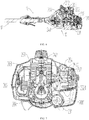
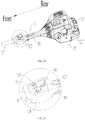
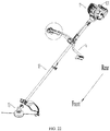
- an embodiment of the present invention provides a garden tool 1 .
- the garden tool 1 includes a power section 11 , a linkage section 12 , a working section 13 and a handle section 14 .
- the garden tool 1 may be a grass trimmer.
- the garden tool 1 may be a hand-held garden tool, such as a hand-held chain saw, a hand-held blower or the like.
- the garden tool 1 may be a walk-behind garden tool, such as a lawn mower.
- the garden tool 1 may also be a backpack-type grass trimmer, a backpack-type chain saws, backpack-type blowers and the like.
- the power section 11 includes a power section casing 111, and the power section casing 111 extends forward to form the handle section 14.
- An end of the linkage section 12 is connected to the handle section 14 , and the other end of the linkage section 12 is connected to the working section 13 , and a power transmission device (not shown in the figures) is included in the linkage section 12 to transmit the torque output by the power section 11 to the working section 13 .
- a gasoline engine 2 is included in the power section casing 111 .
- the gasoline engine 2 includes an engine block 201 , a fuel tank 2011, a cylinder 2022, a piston 203 , a crankshaft 204 and a crankcase 2041.
- a flywheel 243 connected to a front end of the crankshaft 204 and the structure of the gasoline engine 2 are prior arts and will not be described in detail.
- fuel in the cylinder 2022 is combusted to drive the piston 203 to move, and reciprocating motion of the piston 203 is converted into continuous rotation of the crankshaft 204 by the connecting rod.
- the rotation of the crankshaft 204 is transmitted to the power section 11 through the power transmission device.
- the power unit 11 includes a cutting line or a blade, and the power transmission device transmits the rotation of the crankshaft 204 to the cutting line or the blade to perform grass cutting.
- the grass trimmer includes a control system.
- the control system includes a single controller 21 , at least one sensor 22 and an operator 102 .
- the gasoline engine 2 further includes a starting system 23 , an ignition system 24 and a fuel supply system 25 , three of which are disposed in the engine block 201 .
- the sensor 22 collects at least one working condition signal of the grass trimmer, and in particular collects at least one working condition signal of the gasoline engine 2 .
- the operator 102 is physically operated by a user to issue at least one user command signal for controlling the grass trimmer, and the controller 21 receives the working condition signal and controls the ignition system 24 and the fuel supply system 25 according to the working condition signal received.
- the controller 21 also receives the user command signal and performs at least one of following control actions on the grass trimmer: starting, flameout, and adjusting a fuel supply amount, based on the user command signal received.
- the controller 21 is disposed in the power unit casing 111 , preferably disposed on the gasoline engine 2 . In another embodiment, the controller 21 may also be disposed elsewhere in the grass trimmer.
- the operator 102 is disposed separately from the controller 21. Specifically, as shown in Figs. 4 to 6 , the controller 21 is disposed in the power unit casing 111, and the operator 102 is disposed at the front end of the handle section 14 .
- the handle section 14 includes a grip portion 141, and the operator 102 is disposed in front of the grip portion 141 .
- the controller 21 and the operator 102 are connected by a communication wire 2012 .
- the controller 21 and the operator 102 are equipped with wireless communication devices, and the controller 21 and the operator 102 communicate with each other through wireless signals.
- the operator 102 is separately disposed from the grass trimmer, i.e., the operator 102 may be disposed on a separate remote control that communicates with the controller 21 through a communication wire or wireless signals.
- the operator 102 may be an independent intelligent terminal, such as a desktop computer or a mobile terminal (like a mobile phone, a laptop, a tablet, etc.), activating a user operation instruction through a software program, and performing communication through a communication wire or wireless signals.
- a desktop computer or a mobile terminal (like a mobile phone, a laptop, a tablet, etc.)
- a mobile terminal like a mobile phone, a laptop, a tablet, etc.
- activating a user operation instruction through a software program and performing communication through a communication wire or wireless signals.
- the grass trimmer may further include a detachably connected DC (direct current) power source 101 .
- the DC power source 101 may be a rechargeable lithium-ion battery pack.
- a single DC power source 101 is used to power the entire grass trimmer through the controller 21 .
- a power supply mounting section 1111 is disposed on the power unit casing 111 , the DC power source 101 is detachably mounted to the power source mounting portion 1111, and the DC power source 101 is electrically connected to the controller 21 .
- a power module 1011 is further included between the DC power source 101 and the controller 21 for regulating voltage and/or current of the DC power source 101 .
- the operator 102 includes a first operation key 1021 , a second operation key 1022, a third operation key 1023, a fourth operation key 1024 and a fifth operation key 1025.
- the first operation key 1021, the second operation key 1022 and the third operation key 1023 may be rocker switches distributed on an upper surface of a front part of the operator 102
- the fourth operation key 1024 may be a trigger switch disposed under a rear part of the operator 102
- the five operation keys 1025 may be a trigger switch disposed above the rear part of the operator 102 and opposed to the fourth operation key 1024.
- the first operation key 1021 is a master switch
- the second operation key 1022 is a start switch
- the third operation key 1023 is a flameout switch
- the fourth operation key 1024 is a fuel supply adjustment switch
- the fifth operation key 1025 is a fuel supply lock switch.
- the controller 21 controls the fuel supply system 25 to adjust the fuel supply amount according to the state of the fuel supply adjustment switch; when the fuel supply doesn't need to be adjusted for a long time, the user can press the fuel supply lock switch, so the controller 21 locks the fuel supply amount according to the state of the fuel supply lock switch, and the fuel supply adjustment switch could be released.
- the flameout switch can be pressed to make the controller 21 stop the gasoline engine 2 .
- the master switch can be pressed again to disconnect the circuit system of the grass trimmer.
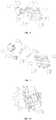
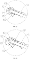
- the starting system 23 includes a starter motor 231 and a speed reduction unit 232.
- the starter motor 231 is disposed below the cylinder 2022 to avoid a high temperature region.
- the starter motor 231 includes a starter motor output shaft 2311.
- the starter motor output shaft 2311 extends rearward along the axial direction of the grass trimmer and is connected to an input gear 2321 of the speed reduction unit 232.
- An output gear 2323 of the speed reduction unit 232 passes through a clutch unit and is connected to a rear end of the crankshaft 204.
- the speed reducing unit 232 may be multistage gears, at least including a transmission gear 2322 cooperating with the input gear 2321 and the output gear 2323 cooperating with the transmission gear 2322 .
- the input gear 2321 is coaxially fixedly connected with the starter motor output shaft 2311, and the input gear 2321 is rotated at the same angular velocity as the starter motor output shaft 2311 .
- the transmission gear 2322 includes a first tooth section 2322 a meshing with the input gear 2321 , and a second tooth section 2322 b disposed coaxially with the first tooth section 2322 a and meshing with the output gear 2323 .
- the diameter of the second tooth section 2322 b is larger than the diameter of the input gear 2321 , and is smaller than the diameter of the first tooth section 2322 a. At the same time, the diameter of the first tooth section 2322 a is smaller than the diameter of the output gear 2323 .
- the first tooth section 2322 a and the second tooth section 2322 b may be integrally formed. In another embodiment, the first tooth section 2322 a and the second tooth section 2322 b may be separately disposed, as long as both of which are synchronously rotated at the same angular velocity.
- the clutch unit may include a clutch drum 2332 disposed on the crankshaft 204 , and a ratchet wheel 2331 contacting with or departing from the clutch drum 2332 and driven by the output gear 2323.
- the clutch drum 2332 includes a disk body section which is substantially rectangular shaped, a pair of pawls 2332 a disposed on opposite corners of the disk body section, and a pair of torsion springs 2332 c respectively sleeved on the pawls 2332 a .
- the pawl 2332 a includes a pawl shaft 2332 b sleeved by the torsion spring 2332 c, and a contact surface 2332 d at an end away from the pawl shaft 2332 b.
- the disk body section includes a pair of partial curved faces oppositely disposed.
- the ratchet wheel 2331 is at least partially curved, and includes a ratchet cavity 2331 a having a circular cross section, a pair of ratchet protrusions 2331 b disposed outside the ratchet cavity 2331 a and correspondingly engaged with on the pawls 2332 a with unidirectional pressure, a fixing member disposed in a center of the cavity 2331a and coaxially fixed to the output gear 2323 , and a gasket sleeved on the fixing member.
- Each of the ratchet protrusions 2331 b includes a mating face 2331 c that abuts against the contact face 2332 d.
- the contact surface 2332 d and the mating surface 2331 c are both planar.
- the ratchet protrusion 2331 b in a clockwise direction, the ratchet protrusion 2331 b abuts against the contact surface 2332 d of the pawl 2332 a through the mating surface 2331 c; however in an anti-clockwise direction, since outer surface of the ratchet protrusion 2331 b is at least partially curved, the ratchet protrusion 2331 b and the pawl 2332 a cannot abuts against each other and consequently separated from each other.
- an energy storage member is preferably included and disposed inside the output gear 2323 , and is preferably a coil spring 234 , a center of which is coaxial with a center of the output gear 2323 .
- the coil spring 234 can reduce impacts between components at a time of starting, so as to prolong service life of the starting system 23 .
- the coil spring 234 includes an inner end 2341 disposed in an inner side and an outer end 2342 disposed in an outer side. A portion between the inner end 2341 and the outer end 2342 is multi-layer winded to store or release energy, and the portion winded can be contracted or expanded.
- the output gear 2323 includes a receiving groove 2323 a disposed outside for receiving the outer end 2342 of the coil spring 234 , and a hook 2323 b disposed on a side of the receiving groove 2323 a and engaged with the outer end 2342 of the coil spring 234 .
- the energy storage member may also be a torsion spring.
- the starter motor output shaft 2311 is rotated at a high speed to drive the input gear 2321 to rotate, the first tooth section 2322 a is rotated by gear meshing, the second tooth portion 2322 b coaxial with the first tooth section 2322 a is also driven to rotate correspondingly, and the output gear 2323 is driven to rotate by gear meshing.
- pressure is continuously applied to the coil spring 234 , and the coil spring 234 continuously stores the kinetic energy of the motor. Once the coil spring 234 provides an elastic force greater than a resistance force provided by the crankshaft 204 , the coil spring 234 will release energy to the crankshaft 204 through the clutch unit.
- the clutch drum 2332 can only be rotated in one direction, and one direction transmission is achieved to drive the crankshaft 204 to rotate, thus an electric start of the gasoline engine 2 is achieved.
- the crankshaft 204 will be rotated at a high speed, and centrifugal force of the crankshaft 204 will disengage the clutch drum 2332 from the ratchet wheel 2331 to ensure that the high-speed rotation of the crankshaft 204 has no effect on the ratchet wheel 2331 , so that the ratchet wheel 2331 can remain stationary and the speed reduction unit 232 is ensured to be stopped.
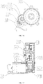
- the DC power source 101 is disposed behind the speed reduction unit 232 , a crankcase 2014 is included and disposed in front of the speed reduction unit 232 , both the starter motor 231 and the crankshaft 204 are connected to a front part of the speed reduction unit 232 , and the controller 21 is disposed below the DC power source 101.
- the ignition system 24 may include an ignition coil 241 boosting device 241 , a spark plug 242 connected to an output end of the ignition coil 241 boosting device 241 , and a second sensor 222 disposed on the flywheel 243 or the engine block 201 .
- the second sensor 222 includes inductive elements and a Hall element disposed corresponding to the inductive elements.
- the inductive elements are disposed on the flywheel 243 and are magnets, the number of the inductive elements is at least two, and the Hall element is disposed on the engine block 201 and the number of the Hall element is one.
- the Hall element may also be replaced by a photoelectric element or another component alike.
- the inductive element may include a positioning magnet 2432 for initial positioning, and a measuring magnet 2431 for rotational speed measurement.
- the positioning magnet 2432 is also referred to as a top dead center positioning magnet.
- the inductive elements are disposed in the circumferential direction of the flywheel 243 .
- the gasoline engine 2 further includes a third sensor, and the third sensor is a temperature sensor for collecting an ambient temperature signal.
- the boosting device 241 raises an output voltage of the lithium-ion battery pack to an ignition voltage to provide sufficient energy for igniting air-fuel mixture.
- the output voltage of the lithium-ion battery pack is 6 V to 12 V, and the ignition voltage is 10,000 V to 30,000 V.
- the boosting device 241 may include multi-stage boosting modules.
- the boosting device 241 includes a primary boosting module and a secondary boosting module. The primary boosting module raises the output voltage of the lithium-ion pack to 200 V- 250 V, and the secondary boosting module raises the output voltage from 220 V to 250 V to the ignition voltage.
- the output voltage of the lithium-ion battery pack is 6 V to 7.2 V
- the boosting device 241 firstly raises the output voltage of the lithium-ion battery pack to 220 V by using series inductance, and then raises the output voltage of 220 V to the ignition voltage, which is 15,000 V to 30,000 V
- the lithium-ion battery pack is used as the DC power source 101 , a rotational speed of the flywheel 243 is detected by the second sensor 222 to determine an ignition advance angle, a current temperature is detected by the third sensor, and the controller 21 raises the output voltage of the DC power source 101 through the boosting device 241 .
- the controller 21 calculates the ignition advance angle and the ignition voltage currently required according to current operating conditions of rotating speed, working time, temperature and the like, and then the ignition system 24 generates an electric spark of corresponding energy through the spark plug 242 , according to an internal calculation result of the controller 21 .
- the electric spark causes the air-fuel mixture in the cylinder 202 to burn, so as to push the piston 203 to reciprocate, thus the grass trimmer can work in an ideal working state.
- This allows ignition to be achieved at a very low speed, specifically, the current temperature can be detected by a temperature sensor and the ignition voltage is raised when the current temperature is low. Meanwhile, the ignition advance angle and the ignition voltage are also controlled by the controller, the ignition process can be triggered when the air-fuel mixture in the cylinder 202 is at the highest concentration, so that a maximum spark can be generated to make the start of the gasoline engine 2 easier and higher efficient.
- the ignition advance angles at different rotational speeds can be controlled at optimal states by detecting the rotational speed in advance, so that working efficiency of the gasoline engine system at all speed states can be improved. Furthermore, by using the controller to precisely control the ignition advance angle and voltage, when the load of the gasoline engine changes drastically, compared with the prior ignition system (as shown in Fig.
- the controller provided by embodiments of the present invention can adjust the ignition advance angle in time by executing program algorithm with reference to positions and rotational speeds of the flywheel measured by a sensor.
- the obtained relationship among ignition timing, ignition voltage and rotational speeds is shown in Fig. 26 , which makes the grass trimmer work more stable.
- the gasoline engine 2 may be a carburetor type gasoline engine
- the fuel supply system 25 may include a carburetor 254 , an automatic choke control unit 251 , and an automatic fuel throttle control unit 252 .
- the carburetor 254 includes an intake passage 2541 with an intake port, and the automatic choke control unit 251 and the automatic fuel throttle control unit 252 are disposed on the carburetor 254 .
- the automatic choke control unit 251 includes a choke shaft 2515 and a choke valve 2511 mounted on the choke shaft 2515 , and the choke valve 2511 is used to open or close the intake passage 2541 .
- the automatic choke control unit 251 further includes a choke actuator 2512 and a choke transmission unit connected to the choke actuator 2512 , and the choke transmission unit is mated with the choke shaft 2515 .
- the choke valve 2511 is coaxially rotated with the choke shaft 2515 , and the opening and closing of the intake passage 2541 may also be achieved through reciprocating movements of the choke valve 2511 .
- the choke shaft 2515 penetrates into the intake passage 2541 of the carburetor 254 and is fixedly or detachably connected to the choke valve 2511 , so that the choke valve 2511 can be rotated coaxially with the choke shaft 2515 .
- the choke valve 2511 is located in the intake passage 2541 and can be used to open the intake passage 2541 to let air enter the cylinder 202 .
- the carburetor 254 further includes a self-locking unit used to lock the choke valve 2511 and an unlocking unit used to unlock the choke valve 2511 .
- the self-locking unit can be found in the prior art, and the unlocking unit can unlock the self-locking unit by means of refueling, which is also a prior art, structures of the self-locking unit and the unlocking unit will not be described in detail.
- the choke transmission unit includes a passive cam 2514 sleeved on the choke shaft 2515 , and an active cam 2513 that cooperates with the passive cam 2514 and is connected to an output end of the choke actuator 2512 .
- the active cam 2513 includes an active cam axle hole 2513 b sleeved on the output end of the choke actuator 2512 , and a projection 2513 a coordinating with the passive cam 2514 , the extending direction of the projection 2513 a being parallel to the axial direction of the choke shaft 2515 .
- the passive cam 2514 includes a passive cam axle bore 2514 a sleeved on the choke shaft 2515.
- the choke transmission unit may indirectly drive the choke valve 2511 through the choke shaft 2515 , or may directly drive the choke valve 2511 .
- the structures of the passive cam 2514 and the active cam 2513 used in above embodiment of the present invention are simple, reliable and low-cost, however the driving manner of the choke transmission unit may also apply a belt, a chain, a hinge or a pendulum to achieve an object of the present invention.
- the choke actuator 2512 may be an electric motor, a combination of an electric motor and a reduction gearbox, an electromagnetic device, or a pneumatic device.
- the electric motor may be a DC or AC motor workable in forward and reverse directions, also called as a servo motor.
- a DC servo motor is preferred to achieve a small structure, large torque, and programmable control.
- the choke valve 2511 and the passive cam 2514 are fixed to the same choke shaft 2515 , and are rotatable with the choke shaft 2515 .
- the choke shaft 2515 is installed in the intake passage 2541 inside the carburetor 254 and can be rotated. Therefore, as long as the passive cam 2514 is rotated, the choke valve 2511 can be rotated by the choke shaft 2515 , thus an air intake amount can be adjusted.
- the choke valve 2511 is closed by using the passive cam 2514 , the choke valve 2511 is maintained in a closed state by the self-locking unit of the carburetor 254 . When the throttle being raised, the self-locking unit is unlocked, and the choke valve 2511 is opened.
- the choke actuator 2512 which may be a motor workable in forward and reverse directions, can drive the active cam 2513 to rotate, and the active cam 2513 can further drive the passive cam 2514 to rotate to close the choke valve 2511 .
- the motor works forwardly to drive the driving cam 2513 to drive the passive cam 2514 to close the choke valve 2511 .
- the motor will work reversely and reset, so that the motor is disconnected from the choke transmission unit, and the choke valve 2511 will be maintained in the closed state by the self-locking unit.
- the self-locking unit is unlocked, and the choke valve 2511 is restored to an open state.
- the automatic fuel throttle control unit 252 includes a throttle shaft 2526 and a throttle 2521 mounted on the throttle shaft 2526 .
- the throttle 2521 is used to open or close the intake passage 2541 .
- the automatic fuel throttle control unit 252 further includes a throttle actuator 2522 and a throttle transmission unit connected with the throttle actuator 2522 .
- the throttle transmission unit is also connected to the throttle shaft 2526 .
- the throttle transmission unit cooperates with an end of the throttle shaft 2526 through a throttle cable 2524 , and the throttle 2521 is rotated coaxially with the throttle shaft 2526 .
- the throttle cable 2524 may be a substantially rigid rod.
- the throttle cable 2524 may be a flexible rod or wire.
- the throttle transmission unit includes a rack 2525 fixed to the throttle cable 2524 , and a throttle drive gear 2522 b cooperating with the rack 2525 and connected to an output end of the throttle actuator 2522 .
- the throttle transmission unit may directly cooperate with an end of the throttle shaft 2526 , which can also achieve the object of the present invention.
- the rack and gear transmission structure applied by the throttle transmission unit in above embodiment of the present invention is simple, reliable, and low-cost, however the driving manner of the throttle transmission unit may also apply a belt, a chain, a hinge or a pendulum to achieve an object of the present invention.
- the automatic fuel throttle control unit 252 further includes a rotating end 2523 and a locking end 2527 respectively located at opposite ends of the throttle shaft 2526 .
- the rotating end 2523 is fixed to the throttle cable 2524 , and the locking end 2527 cooperates with the automatic choke control unit 251 .
- the choke valve 2511 is also driven to open, thereby achieving linkage between the throttle 2521 and the choke valve 2511 .
- the rotating end 2523 is at least partially arcuate and includes a plurality of fixing holes 2523 a arranged in an arc shape, wherein one fixing hole 2523 a is fastened to an end of the throttle wire 2524 .
- the throttle actuator 2522 may be an electric motor, a combination of an electric motor and a reduction gearbox, an electromagnetic device, or a pneumatic device.
- the electric motor may be a DC or AC motor workable in forward and reverse directions, also called as a servo motor.
- a DC servo motor is preferred to achieve a small structure, large torque, and programmable control.
- the throttle 2521 is fixed to the throttle shaft 2526 and is rotatable with the throttle shaft 2526 , and the throttle shaft 2526 is mounted in the intake passage 2541 inside the carburetor 254 .
- the throttle 2521 is in a closed state.
- the controller 21 controls the throttle actuator 2522 to operate, and drives the throttle drive gear 2522 b to rotate by a throttle output shaft 2522a , thereby driving the rack 2525 to perform linear motion, and further driving the throttle cable 2524 to perform linear motion. Since the throttle cable 2524 is connected to the rotating end 2523 , the rotating end 2523 drives the throttle shaft 2526 at the center thereof to rotate together, so that the throttle 2521 is opened.
- the gasoline engine 2 further includes a first sensor 221 , which is a temperature sensor for measuring an ambient temperature.
- the first sensor 221 and the third sensor may be integrated into one sensor.
- the controller 21 controls the motor to work to close the choke valve 2511 , and, and the choke valve 2511 and the throttle 2521 are opened automatically when the gasoline engine 2 returns to normally working. It can be seen that the whole process is simple and convenient, and starting states of the gasoline engine 2 can be automatically set in various starting environments, which reduces users' intervention on the start of the gasoline engine 2 , and also reduces users' labor intensity.
- a single controller is applied by embodiments of the present embodiment to control the grass trimmer, and a battery pack is used to supply power to the grass trimmer through the controller, so that operation of the grass trimmer can be more convenient and more easy, and a concentrated operation device (e.g. a control panel) can be used to control the grass trimmer conveniently.
- a concentrated operation device e.g. a control panel
- the use of the controller can improve the cooperation of various systems, so that the grass trimmer can be maintained in the best working condition.
- the controller can perform unified control of a starting system, a fuel supply system and an ignition system, according to commands issued by a user and the working condition signal collected by sensors, so that optimal matching parameters can be achieved among the systems, and the parameters can be automatically adjusted according to changes of working conditions.
- a battery pack of a prior electric start grass trimmer since a battery pack of a prior electric start grass trimmer only supplies power for the starting system during a starting phase, and the ignition system gets power from an additional generator during a normal working phase, utilization of the battery pack is extremely low and product cost is increased.
- a single battery pack is used to power the entire grass trimmer including the starting system and the ignition system, which improves the utilization of the battery pack and reduces the product cost.
- the gasoline engine 2 of the present embodiment is an EFI (electronic fuel injection) gasoline engine.
- the fuel supply system 25 may include an electric fuel injector 253 .
- the controller 21 adjusts a fuel injection amount and an air-fuel ratio through the electric fuel injector 253 , according to the ambient temperature signal measured by the first sensor 211 .
- the present embodiment provides a grass trimmer using a gasoline engine.
- the difference from Embodiment 1 lies in that the operator 102 includes a panel, and the first operation key 1021 , the second operation key 1022 and the third operation key 1023 are flat push-button switch disposed on the panel.
- a convex portion 1026 is provided between the first operation key 1021 and the second operation key 1022 to prevent the first operation key 1021 and the second operation key 1022 from being pressed simultaneously.
- the convex portion 1026 When a user presses the panel from a top direction using a body section part (usually using a palm or a finger), if only the first operation key 1021 or the second operation key 1022 is pressed, the convex portion 1026 will not hinder the movement of the user's body section part. If the first operation key 1021 and the second operation key 1022 are pressed simultaneously by mistakes, the convex portion 1026 will hinder the movement of the user's body section part. On the one hand the first operation key 1021 and the second operation key 1022 are prevented from being pressed simultaneously, and on the other hand the convex portion 1026 may cause an unpleasant touch to user's body section part, alerting the user that this is an error operation.
- the distance between the first operation key 1021 and the second operation key 1022 can be further reduced, thereby reducing entire area of the panel or providing more installation and operation space for other components on the panel.
- the distance between the two operation keys 102 is increased.
- spacing between inner sides of the first operation key 1021 and the second operation key 1022 should be not less than 25 mm.
- the spacing between inner sides of the first operation key 1021 and the second operation key 1022 can be not less than 20 mm.
- the spacing between inner sides of the two can be not less than 6 mm.
- the spacing between inner sides of the two can be not less than 12 mm.
- selections of the first operation key 1021 and the second operation key 1022 are not limited to above types of switches, so the spacing between inner sides of the two may also be specifically adjusted according to the types of switches selected.
- the difference from Embodiment 3 lies in that the handle section 14 of the grass trimmer in the present embodiment is a U-shaped handle mounted on the linkage section 12 , and two grip portions 141 are respectively included at both ends of the U-shaped handle.
- the operator 102 is disposed on one of the two grip portions 141 .
- the difference from Embodiment 4 lies in that, in the operator 102 of the grass trimmer provided by this embodiment, the fifth operation key 1025 is disposed below a side of the panel.
- the fifth operation key 1025 is a fuel supply lock switch.
Applications Claiming Priority (4)
| Application Number | Priority Date | Filing Date | Title |
|---|---|---|---|
| CN201610024655.1A CN105484876A (zh) | 2016-01-15 | 2016-01-15 | 电动油门装置及其控制系统 |
| CN201610024372.7A CN105545562A (zh) | 2016-01-15 | 2016-01-15 | 小型汽油机 |
| EP17738208.2A EP3404239B1 (en) | 2016-01-15 | 2017-01-13 | Garden tool |
| PCT/CN2017/071175 WO2017121395A1 (zh) | 2016-01-15 | 2017-01-13 | 园林工具 |
Related Parent Applications (2)
| Application Number | Title | Priority Date | Filing Date |
|---|---|---|---|
| EP17738208.2A Division-Into EP3404239B1 (en) | 2016-01-15 | 2017-01-13 | Garden tool |
| EP17738208.2A Division EP3404239B1 (en) | 2016-01-15 | 2017-01-13 | Garden tool |
Publications (1)
| Publication Number | Publication Date |
|---|---|
| EP3663567A1 true EP3663567A1 (en) | 2020-06-10 |
Family
ID=59310766
Family Applications (2)
| Application Number | Title | Priority Date | Filing Date |
|---|---|---|---|
| EP17738208.2A Active EP3404239B1 (en) | 2016-01-15 | 2017-01-13 | Garden tool |
| EP20153836.0A Withdrawn EP3663567A1 (en) | 2016-01-15 | 2017-01-13 | Garden tool |
Family Applications Before (1)
| Application Number | Title | Priority Date | Filing Date |
|---|---|---|---|
| EP17738208.2A Active EP3404239B1 (en) | 2016-01-15 | 2017-01-13 | Garden tool |
Country Status (3)
| Country | Link |
|---|---|
| US (1) | US10851721B2 (zh) |
| EP (2) | EP3404239B1 (zh) |
| WO (1) | WO2017121395A1 (zh) |
Families Citing this family (3)
| Publication number | Priority date | Publication date | Assignee | Title |
|---|---|---|---|---|
| CN105508117A (zh) * | 2016-01-15 | 2016-04-20 | 苏州科瓴精密机械科技有限公司 | 便携式汽油工具及其电子点火系统 |
| CN109184960A (zh) * | 2018-10-24 | 2019-01-11 | 苏州科瓴精密机械科技有限公司 | 汽油机的自动风门控制系统、控制方法及汽油机 |
| EP3806273A1 (en) | 2019-10-11 | 2021-04-14 | Black & Decker Inc. | Power tool receiving different capacity batttery packs |
Citations (7)
| Publication number | Priority date | Publication date | Assignee | Title |
|---|---|---|---|---|
| US20060042574A1 (en) * | 2004-08-24 | 2006-03-02 | Tomomasa Nishikawa | Combustion-type power tool providing specific spark energy |
| US20090020094A1 (en) * | 2006-02-01 | 2009-01-22 | Husqvarna Zenoah Co., Ltd. | Engine start device for manual work machine, having small-sized electric motor, and manual work machine having the start device mounted thereon |
| EP2108812A1 (en) * | 2008-04-09 | 2009-10-14 | Techtronic Industries Company Limited | Starter system for internal combustion engine |
| US20110146610A1 (en) * | 2009-12-17 | 2011-06-23 | Andreas Stihl Ag & Co. Kg. | Handheld work apparatus |
| EP2474218A1 (en) * | 2009-09-02 | 2012-07-11 | Makita Corporation | Plant cutter |
| US20140318488A1 (en) * | 2011-09-14 | 2014-10-30 | Kokusan Denki Co., Ltd. | Control device for internal combustion engine |
| US20140366830A1 (en) * | 2012-01-24 | 2014-12-18 | Hitachi Koki Co., Ltd. | Engine-powered tool |
Family Cites Families (35)
| Publication number | Priority date | Publication date | Assignee | Title |
|---|---|---|---|---|
| US3620200A (en) * | 1969-07-08 | 1971-11-16 | Ambac Ind | Booster circuit for ignition systems |
| US4250842A (en) * | 1977-11-07 | 1981-02-17 | The Bendix Corporation | Electronic injection carburetor |
| DE3722048A1 (de) * | 1987-07-03 | 1989-01-12 | Bosch Gmbh Robert | Brennkraftmaschine, insbesondere ottomotor |
| DE4037092A1 (de) * | 1990-11-22 | 1992-05-27 | Zahnradfabrik Friedrichshafen | Verfahren zur steuerung des drehmoments einer brennkraftmaschine |
| JP3827059B2 (ja) * | 2000-07-11 | 2006-09-27 | 本田技研工業株式会社 | エンジンの始動制御装置 |
| JP4270426B2 (ja) * | 2001-01-31 | 2009-06-03 | スターテング工業株式会社 | エンジンの始動装置 |
| US6752110B2 (en) * | 2002-09-20 | 2004-06-22 | Briggs & Stratton Corporation | Electromechanical choke system for an internal combustion engine |
| US7798128B2 (en) * | 2003-09-10 | 2010-09-21 | Pc/Rc Products, L.L.C. | Apparatus and process for controlling operation of an internal combustion engine having an electronic fuel regulation system |
| JP4199688B2 (ja) * | 2004-03-18 | 2008-12-17 | 本田技研工業株式会社 | オートチョーク装置 |
| US7525287B2 (en) | 2004-10-08 | 2009-04-28 | Husqvarna Zenoah Co., Ltd. | Battery pack for driving electric motor of compact engine starting device, engine starting device driven by the battery pack, and manual working machine having the engine starting device |
| DE102005016067B4 (de) * | 2005-04-07 | 2007-06-21 | Siemens Ag | Verfahren zur Erhöhung der Start-Reproduzierbarkeit bei Start-Stopp-Betrieb einer Brennkraftmachine |
| DE102006038277B4 (de) | 2006-08-16 | 2021-01-21 | Andreas Stihl Ag & Co. Kg | Verfahren zum Regeln der Zusammensetzung eines Kraftstoff/Luft-Gemisches für einen Verbrennungsmotor |
| JP4868523B2 (ja) * | 2007-04-04 | 2012-02-01 | 京都電機器株式会社 | エンジンにおけるオートチョーク装置 |
| JP2009185695A (ja) * | 2008-02-06 | 2009-08-20 | Walbro Japan Inc | 層状掃気用気化器 |
| US8434444B2 (en) * | 2008-05-27 | 2013-05-07 | Briggs & Stratton Corporation | Engine with an automatic choke and method of operating an automatic choke for an engine |
| CN101363380A (zh) * | 2008-10-09 | 2009-02-11 | 张和君 | 电控汽油发动机工作系统 |
| CN202047923U (zh) | 2011-05-27 | 2011-11-23 | 山东绿环动力设备有限公司 | 一种四缸燃气发动机控制系统 |
| US9127658B2 (en) * | 2011-11-04 | 2015-09-08 | Briggs & Stratton Corporation | Internal combustion engine including starting system powered by lithium-ion battery |
| US8733072B2 (en) * | 2011-11-04 | 2014-05-27 | Briggs & Stratton Corporation | Starter system for an engine |
| CN103166536B (zh) * | 2011-12-15 | 2018-01-16 | 德昌电机(深圳)有限公司 | 直流起动器及割草机 |
| DE102012012798B4 (de) | 2012-06-28 | 2014-11-13 | Andreas Stihl Ag & Co. Kg | Arbeitsgerät mit einer Bremseinrichtung |
| EP3199797B1 (en) | 2013-05-24 | 2023-05-10 | Denso Corporation | Ignition control apparatus |
| CN103758671A (zh) | 2014-01-14 | 2014-04-30 | 曲日 | 无噪声启动汽油发动机及其启动方法 |
| CN205638762U (zh) | 2016-01-15 | 2016-10-12 | 苏州科瓴精密机械科技有限公司 | 便携式汽油工具及其电子点火系统 |
| CN105484899B (zh) * | 2016-01-15 | 2018-09-18 | 苏州科瓴精密机械科技有限公司 | 便携式汽油机及其自动风门控制系统 |
| CN205503286U (zh) * | 2016-01-15 | 2016-08-24 | 苏州科瓴精密机械科技有限公司 | 电动油门装置及其控制系统 |
| CN205638760U (zh) * | 2016-01-15 | 2016-10-12 | 苏州科瓴精密机械科技有限公司 | 小型汽油机 |
| CN105484876A (zh) * | 2016-01-15 | 2016-04-13 | 苏州科瓴精密机械科技有限公司 | 电动油门装置及其控制系统 |
| CN205638761U (zh) * | 2016-01-15 | 2016-10-12 | 苏州科瓴精密机械科技有限公司 | 便携式汽油工具 |
| CN205370829U (zh) * | 2016-01-15 | 2016-07-06 | 苏州科瓴精密机械科技有限公司 | 便携式汽油工具 |
| CN105464875B (zh) * | 2016-01-15 | 2019-04-05 | 苏州科瓴精密机械科技有限公司 | 便携式汽油工具 |
| CN205638728U (zh) * | 2016-01-15 | 2016-10-12 | 苏州科瓴精密机械科技有限公司 | 便携式汽油机及其自动风门控制系统 |
| CN105545562A (zh) * | 2016-01-15 | 2016-05-04 | 苏州科瓴精密机械科技有限公司 | 小型汽油机 |
| CN105508117A (zh) | 2016-01-15 | 2016-04-20 | 苏州科瓴精密机械科技有限公司 | 便携式汽油工具及其电子点火系统 |
| CN105673290B (zh) * | 2016-01-15 | 2018-11-09 | 苏州科瓴精密机械科技有限公司 | 便携式汽油工具 |
-
2017
- 2017-01-13 EP EP17738208.2A patent/EP3404239B1/en active Active
- 2017-01-13 EP EP20153836.0A patent/EP3663567A1/en not_active Withdrawn
- 2017-01-13 WO PCT/CN2017/071175 patent/WO2017121395A1/zh active Application Filing
- 2017-01-13 US US16/070,421 patent/US10851721B2/en active Active
Patent Citations (7)
| Publication number | Priority date | Publication date | Assignee | Title |
|---|---|---|---|---|
| US20060042574A1 (en) * | 2004-08-24 | 2006-03-02 | Tomomasa Nishikawa | Combustion-type power tool providing specific spark energy |
| US20090020094A1 (en) * | 2006-02-01 | 2009-01-22 | Husqvarna Zenoah Co., Ltd. | Engine start device for manual work machine, having small-sized electric motor, and manual work machine having the start device mounted thereon |
| EP2108812A1 (en) * | 2008-04-09 | 2009-10-14 | Techtronic Industries Company Limited | Starter system for internal combustion engine |
| EP2474218A1 (en) * | 2009-09-02 | 2012-07-11 | Makita Corporation | Plant cutter |
| US20110146610A1 (en) * | 2009-12-17 | 2011-06-23 | Andreas Stihl Ag & Co. Kg. | Handheld work apparatus |
| US20140318488A1 (en) * | 2011-09-14 | 2014-10-30 | Kokusan Denki Co., Ltd. | Control device for internal combustion engine |
| US20140366830A1 (en) * | 2012-01-24 | 2014-12-18 | Hitachi Koki Co., Ltd. | Engine-powered tool |
Also Published As
| Publication number | Publication date |
|---|---|
| US20190032583A1 (en) | 2019-01-31 |
| EP3404239A1 (en) | 2018-11-21 |
| EP3404239A4 (en) | 2019-08-07 |
| EP3404239B1 (en) | 2024-05-01 |
| WO2017121395A1 (zh) | 2017-07-20 |
| US10851721B2 (en) | 2020-12-01 |
Similar Documents
| Publication | Publication Date | Title |
|---|---|---|
| EP3404239B1 (en) | Garden tool | |
| US9759175B2 (en) | Starter system for an engine | |
| US9828966B2 (en) | Lawn mower starter system | |
| EP2838336B1 (en) | Starter system for an engine | |
| EP3604013A1 (en) | Hybrid vehicle | |
| CN105593514B (zh) | 包括由锂离子电池供电的电启动系统的内燃式发动机 | |
| US3955653A (en) | Rotary mower blade arrester apparatus | |
| US11913417B2 (en) | Internal combustion engine with electric starting system | |
| EP3821121B1 (en) | Internal combustion engine with electric starting system | |
| US10260475B2 (en) | Internal combustion engine and garden tool | |
| CN105464875B (zh) | 便携式汽油工具 | |
| CN205638760U (zh) | 小型汽油机 | |
| US20190024611A1 (en) | Internal combustion engine provided with a semi- automatic choke device | |
| WO2013043092A1 (en) | A starter apparatus for starting an internal combustion engine | |
| US9217410B2 (en) | Single point engine control interface | |
| US20240123597A1 (en) | Power trigger mechanism, method of operating a power trigger mechanism, and power tool having the same | |
| KR20180039793A (ko) | 전동캬브레터 | |
| JP2013151863A (ja) | エンジン作業機 | |
| JP2014148932A (ja) | エンジン作業機 | |
| JPH0419360A (ja) | 小形内燃機関の始動装置 |
Legal Events
| Date | Code | Title | Description |
|---|---|---|---|
| PUAI | Public reference made under article 153(3) epc to a published international application that has entered the european phase |
Free format text: ORIGINAL CODE: 0009012 |
|
| STAA | Information on the status of an ep patent application or granted ep patent |
Free format text: STATUS: THE APPLICATION HAS BEEN PUBLISHED |
|
| AC | Divisional application: reference to earlier application |
Ref document number: 3404239 Country of ref document: EP Kind code of ref document: P |
|
| AK | Designated contracting states |
Kind code of ref document: A1 Designated state(s): AL AT BE BG CH CY CZ DE DK EE ES FI FR GB GR HR HU IE IS IT LI LT LU LV MC MK MT NL NO PL PT RO RS SE SI SK SM TR |
|
| STAA | Information on the status of an ep patent application or granted ep patent |
Free format text: STATUS: REQUEST FOR EXAMINATION WAS MADE |
|
| 17P | Request for examination filed |
Effective date: 20200821 |
|
| RBV | Designated contracting states (corrected) |
Designated state(s): AL AT BE BG CH CY CZ DE DK EE ES FI FR GB GR HR HU IE IS IT LI LT LU LV MC MK MT NL NO PL PT RO RS SE SI SK SM TR |
|
| STAA | Information on the status of an ep patent application or granted ep patent |
Free format text: STATUS: EXAMINATION IS IN PROGRESS |
|
| 17Q | First examination report despatched |
Effective date: 20220621 |
|
| STAA | Information on the status of an ep patent application or granted ep patent |
Free format text: STATUS: THE APPLICATION HAS BEEN WITHDRAWN |
|
| 18W | Application withdrawn |
Effective date: 20221006 |