EP3663266B1 - Wasserreiniger und steuerungsverfahren dafür - Google Patents
Wasserreiniger und steuerungsverfahren dafür Download PDFInfo
- Publication number
- EP3663266B1 EP3663266B1 EP19213617.4A EP19213617A EP3663266B1 EP 3663266 B1 EP3663266 B1 EP 3663266B1 EP 19213617 A EP19213617 A EP 19213617A EP 3663266 B1 EP3663266 B1 EP 3663266B1
- Authority
- EP
- European Patent Office
- Prior art keywords
- water
- filter
- quality value
- supplied
- purifier
- Prior art date
- Legal status (The legal status is an assumption and is not a legal conclusion. Google has not performed a legal analysis and makes no representation as to the accuracy of the status listed.)
- Active
Links
Images


Classifications
-
- C—CHEMISTRY; METALLURGY
- C02—TREATMENT OF WATER, WASTE WATER, SEWAGE, OR SLUDGE
- C02F—TREATMENT OF WATER, WASTE WATER, SEWAGE, OR SLUDGE
- C02F1/00—Treatment of water, waste water, or sewage
- C02F1/008—Control or steering systems not provided for elsewhere in subclass C02F
-
- B—PERFORMING OPERATIONS; TRANSPORTING
- B67—OPENING, CLOSING OR CLEANING BOTTLES, JARS OR SIMILAR CONTAINERS; LIQUID HANDLING
- B67D—DISPENSING, DELIVERING OR TRANSFERRING LIQUIDS, NOT OTHERWISE PROVIDED FOR
- B67D1/00—Apparatus or devices for dispensing beverages on draught
- B67D1/08—Details
- B67D1/12—Flow or pressure control devices or systems, e.g. valves, gas pressure control, level control in storage containers
- B67D1/1277—Flow control valves
-
- B—PERFORMING OPERATIONS; TRANSPORTING
- B01—PHYSICAL OR CHEMICAL PROCESSES OR APPARATUS IN GENERAL
- B01D—SEPARATION
- B01D35/00—Filtering devices having features not specifically covered by groups B01D24/00 - B01D33/00, or for applications not specifically covered by groups B01D24/00 - B01D33/00; Auxiliary devices for filtration; Filter housing constructions
- B01D35/14—Safety devices specially adapted for filtration; Devices for indicating clogging
- B01D35/157—Flow control valves: Damping or calibrated passages
- B01D35/1573—Flow control valves
-
- B—PERFORMING OPERATIONS; TRANSPORTING
- B01—PHYSICAL OR CHEMICAL PROCESSES OR APPARATUS IN GENERAL
- B01D—SEPARATION
- B01D61/00—Processes of separation using semi-permeable membranes, e.g. dialysis, osmosis or ultrafiltration; Apparatus, accessories or auxiliary operations specially adapted therefor
- B01D61/02—Reverse osmosis; Hyperfiltration ; Nanofiltration
- B01D61/025—Reverse osmosis; Hyperfiltration
-
- B—PERFORMING OPERATIONS; TRANSPORTING
- B01—PHYSICAL OR CHEMICAL PROCESSES OR APPARATUS IN GENERAL
- B01D—SEPARATION
- B01D61/00—Processes of separation using semi-permeable membranes, e.g. dialysis, osmosis or ultrafiltration; Apparatus, accessories or auxiliary operations specially adapted therefor
- B01D61/02—Reverse osmosis; Hyperfiltration ; Nanofiltration
- B01D61/12—Controlling or regulating
-
- B—PERFORMING OPERATIONS; TRANSPORTING
- B67—OPENING, CLOSING OR CLEANING BOTTLES, JARS OR SIMILAR CONTAINERS; LIQUID HANDLING
- B67D—DISPENSING, DELIVERING OR TRANSFERRING LIQUIDS, NOT OTHERWISE PROVIDED FOR
- B67D1/00—Apparatus or devices for dispensing beverages on draught
- B67D1/0003—Apparatus or devices for dispensing beverages on draught the beverage being a single liquid
- B67D1/0014—Apparatus or devices for dispensing beverages on draught the beverage being a single liquid the beverage being supplied from water mains
-
- C—CHEMISTRY; METALLURGY
- C02—TREATMENT OF WATER, WASTE WATER, SEWAGE, OR SLUDGE
- C02F—TREATMENT OF WATER, WASTE WATER, SEWAGE, OR SLUDGE
- C02F1/00—Treatment of water, waste water, or sewage
- C02F1/001—Processes for the treatment of water whereby the filtration technique is of importance
-
- G—PHYSICS
- G01—MEASURING; TESTING
- G01N—INVESTIGATING OR ANALYSING MATERIALS BY DETERMINING THEIR CHEMICAL OR PHYSICAL PROPERTIES
- G01N27/00—Investigating or analysing materials by the use of electric, electrochemical, or magnetic means
- G01N27/02—Investigating or analysing materials by the use of electric, electrochemical, or magnetic means by investigating impedance
- G01N27/04—Investigating or analysing materials by the use of electric, electrochemical, or magnetic means by investigating impedance by investigating resistance
- G01N27/06—Investigating or analysing materials by the use of electric, electrochemical, or magnetic means by investigating impedance by investigating resistance of a liquid
-
- B—PERFORMING OPERATIONS; TRANSPORTING
- B01—PHYSICAL OR CHEMICAL PROCESSES OR APPARATUS IN GENERAL
- B01D—SEPARATION
- B01D2311/00—Details relating to membrane separation process operations and control
- B01D2311/04—Specific process operations in the feed stream; Feed pretreatment
-
- B—PERFORMING OPERATIONS; TRANSPORTING
- B67—OPENING, CLOSING OR CLEANING BOTTLES, JARS OR SIMILAR CONTAINERS; LIQUID HANDLING
- B67D—DISPENSING, DELIVERING OR TRANSFERRING LIQUIDS, NOT OTHERWISE PROVIDED FOR
- B67D2210/00—Indexing scheme relating to aspects and details of apparatus or devices for dispensing beverages on draught or for controlling flow of liquids under gravity from storage containers for dispensing purposes
- B67D2210/00002—Purifying means
- B67D2210/00005—Filters
- B67D2210/0001—Filters for liquid
-
- C—CHEMISTRY; METALLURGY
- C02—TREATMENT OF WATER, WASTE WATER, SEWAGE, OR SLUDGE
- C02F—TREATMENT OF WATER, WASTE WATER, SEWAGE, OR SLUDGE
- C02F1/00—Treatment of water, waste water, or sewage
- C02F1/28—Treatment of water, waste water, or sewage by sorption
- C02F1/283—Treatment of water, waste water, or sewage by sorption using coal, charred products, or inorganic mixtures containing them
-
- C—CHEMISTRY; METALLURGY
- C02—TREATMENT OF WATER, WASTE WATER, SEWAGE, OR SLUDGE
- C02F—TREATMENT OF WATER, WASTE WATER, SEWAGE, OR SLUDGE
- C02F1/00—Treatment of water, waste water, or sewage
- C02F1/44—Treatment of water, waste water, or sewage by dialysis, osmosis or reverse osmosis
- C02F1/441—Treatment of water, waste water, or sewage by dialysis, osmosis or reverse osmosis by reverse osmosis
-
- C—CHEMISTRY; METALLURGY
- C02—TREATMENT OF WATER, WASTE WATER, SEWAGE, OR SLUDGE
- C02F—TREATMENT OF WATER, WASTE WATER, SEWAGE, OR SLUDGE
- C02F2201/00—Apparatus for treatment of water, waste water or sewage
- C02F2201/002—Construction details of the apparatus
- C02F2201/005—Valves
-
- C—CHEMISTRY; METALLURGY
- C02—TREATMENT OF WATER, WASTE WATER, SEWAGE, OR SLUDGE
- C02F—TREATMENT OF WATER, WASTE WATER, SEWAGE, OR SLUDGE
- C02F2209/00—Controlling or monitoring parameters in water treatment
- C02F2209/001—Upstream control, i.e. monitoring for predictive control
-
- C—CHEMISTRY; METALLURGY
- C02—TREATMENT OF WATER, WASTE WATER, SEWAGE, OR SLUDGE
- C02F—TREATMENT OF WATER, WASTE WATER, SEWAGE, OR SLUDGE
- C02F2209/00—Controlling or monitoring parameters in water treatment
- C02F2209/005—Processes using a programmable logic controller [PLC]
-
- C—CHEMISTRY; METALLURGY
- C02—TREATMENT OF WATER, WASTE WATER, SEWAGE, OR SLUDGE
- C02F—TREATMENT OF WATER, WASTE WATER, SEWAGE, OR SLUDGE
- C02F2209/00—Controlling or monitoring parameters in water treatment
- C02F2209/05—Conductivity or salinity
-
- C—CHEMISTRY; METALLURGY
- C02—TREATMENT OF WATER, WASTE WATER, SEWAGE, OR SLUDGE
- C02F—TREATMENT OF WATER, WASTE WATER, SEWAGE, OR SLUDGE
- C02F2209/00—Controlling or monitoring parameters in water treatment
- C02F2209/11—Turbidity
-
- C—CHEMISTRY; METALLURGY
- C02—TREATMENT OF WATER, WASTE WATER, SEWAGE, OR SLUDGE
- C02F—TREATMENT OF WATER, WASTE WATER, SEWAGE, OR SLUDGE
- C02F2209/00—Controlling or monitoring parameters in water treatment
- C02F2209/40—Liquid flow rate
-
- C—CHEMISTRY; METALLURGY
- C02—TREATMENT OF WATER, WASTE WATER, SEWAGE, OR SLUDGE
- C02F—TREATMENT OF WATER, WASTE WATER, SEWAGE, OR SLUDGE
- C02F2209/00—Controlling or monitoring parameters in water treatment
- C02F2209/44—Time
- C02F2209/445—Filter life
-
- C—CHEMISTRY; METALLURGY
- C02—TREATMENT OF WATER, WASTE WATER, SEWAGE, OR SLUDGE
- C02F—TREATMENT OF WATER, WASTE WATER, SEWAGE, OR SLUDGE
- C02F2301/00—General aspects of water treatment
- C02F2301/02—Fluid flow conditions
- C02F2301/028—Tortuous
Definitions
- the invention relates to a water purifier and a control method thereof.
- a water purifier is a device for filtering water supplied from a water supply source to provide drinking water, and is widely used for a home use.
- a water purifier may be connected to a water supply source, remove suspended or harmful components contained in water by using a filter, and purify water as much as desired according to a manipulation of a user to discharge purified water.
- a water purifier that supplies drinkable water to a user should be provided to a user in a manner that purified water satisfies a predetermined criterion.
- a filter provided in a water purifier is configured in accordance with the water quality of tap water provided from a water source, it is not filtered according to impurities dissolved in water depending on the water quality of water provided to the water purifier.
- the related-art water purifier has problems in that there would be no filtering effect, if water such as groundwater that is different from waterworks is filtered, or the waterworks piping is aged, and the tap water supplied from the waterworks is filtered, and that an optimal action cannot be taken according to the water quality of the water provided to the water purifier.
- CN 107522308 , KR 101210872 and CN 205216585 each disclose a water purifier.
- a water purifier as set out in claim 1.
- a method for controlling a water purifier as set out in claim 12. The invention relates to a water purifier that may select a filter according to water quality of water supplied from a water supply source and filter the water.
- the water purifier includes a water quality sensor configured to measure quality of water that is supplied from a water supply source, a first filter configured to filter by a first method, a second filter configured to filter by a second method, a flow path shifting valve configured to selectively supply water that is supplied from the water supply source to the first filter or the second filter, and a processor configured to control the flow path shifting valve based on a water quality value that is measured by the sensor.
- the first method is a direct-type water purification method
- the second method is a reverse osmosis water purification method
- the processor is configured to control the flow path shifting valve to, based on the measured water quality value being less than a predetermined water quality value supply the water supplied from the water supply source to the first filter, and based on the measured water quality value being greater than a predetermined water quality value, supply the water supplied from the water supply source to the second filter.
- the water purifier further comprises a first water purifying line, which includes a first water purifying line front end formed at the front end of the first filter, and a first water purifying line rear end formed at the rear end of the first filter between the first filter and a water discharge line to discharge purified water, and a second water purifying line which includes a second water purifying line front end formed at the front end of the second filter, and a second water purifying line rear end formed at the rear end of the second filter between the second filter and the water discharge line, and the second water purifying line rear end may be formed to be longer than the first water purifying line rear end.
- the second water purifying line rear end may be disposed in a form to be wound by a plurality of times.
- the water quality sensor may measure electrical conductivity of the water supplied from the water supply source.
- the water purifier may further include a pre-treatment filter receiving the water supplied from the water supply source before the first filter and the second filter, and a post-treatment filter receiving water from the first filter and the second filter.
- the flow path shifting valve may selectively supply the water that is discharged from the pre-treatment filter to the first filter or the second filter.
- the water quality sensor may detect quality of water that is supplied to the pre-treatment filter.
- the water purifier may include a first flow sensor configured to detect an amount of the water that is supplied to the first filter and a second flow sensor configured to detect an amount of the water that is supplied to the second filter.
- the processor may determine whether to replace the first filter based on the amount of water that is measured by the first flow sensor, and determine whether to replace the second filter based on the amount of water that is measured by the second flow sensor.
- the processor may, in response to determination that the first filter needs to be replaced, generate a filter replacement notification signal, and control the flow path shifting valve to supply the water supplied from the water supply source only to the first filter.
- the processor may, based on determination that the second filter needs to be replaced, generate a filter replacement notification signal, and based on the measured water quality value being greater than a predetermined water quality value, not to perform a water discharge command to discharge purified water.
- a method for controlling a water purifier includes measuring quality of water that is suppled from a water supply source; and selectively supplying water that is supplied from the water supply source to the first filter or the second filter based on a measured water quality value.
- the first method is a direct-type water purification method
- the second method is a reverse osmosis water purification method
- the supplying to the first filter or the second filter includes, based on the measured water quality value being less than a predetermined water quality value, supplying the water supplied from the water supply source to the first filter, and based on the measured water quality value being greater than a predetermined water quality value, supplying the water supplied from the water supply source to the second filter.
- the method may further include detecting an amount of the water that is supplied to the first filter and the second filter, respectively.
- Whether to replace the first filter or the second filter may be determined based on the detected amount of water that is supplied to the first filter and the second filter.
- a filter replacement notification signal may be generated, and the water supplied from the water supply source may be supplied only to the second filter.
- a filter replacement notification signal may be generated, and based on the measured water quality value being greater than a predetermined water quality value, a water discharge command to discharge purified water may not be performed.
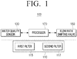
- FIG. 1 is a block diagram illustrating a simple configuration of a water purifier according to an embodiment.
- a water purifier 100 includes a filter 110 including a plurality of filters, a water quality sensor 130 for measuring the water quality of water provided to the water purifier 100 from a water supply source, a flow path shifting valve 150 for selectively providing water provided from the water supply source to a first filter 115 or a second filter 117, and a processor 170 for controlling the flow path shifting valve 150.
- the filter 110 includes a plurality of filters.
- the filter 110 includes the first filter 115 for filtering using a first method and the second filter 117 for filtering using a second method.
- the first filter 115 is composed of a direct-type membrane filter 115 for filtering water using a direct-type water purifying method.
- the filtered water in the filter 110 can be directly supplied to the user by the direct-type water purification, thereby improving the sanitation.
- the first filter 115 functions as a main filter for removing fine contaminants, and may be a filter having a high filtering force such as a hollow fiber membrane filter and a nano trap filter.
- the hollow fiber membrane filter (ultrafiltration filter, UF filter) is a porous filter having pores of a size of tens of nanometers to hundreds of nanometers (nm), and remove contaminants in the water through a large number of micropores distributed on the surface of the membrane.
- the nanotrap filter is a filter for adsorbing and removing bacteria, micro-viruses, and harmful substances by electrostatic force.
- the filter used in the first filter 115 is not limited to the hollow fiber membrane filter and the nano trap filter described above, but various filters having a direct-type water purification system which remove fine contaminants can be used.
- the second filter 117 is composed of a reverse osmosis filter for filtering water using reverse osmosis water purification method.
- the second filter 117 may include a reverse osmosis membrane and may purify water supplied through reverse osmosis, and may filter not only heavy metals such as lead and arsenic but also sodium, various pathogens, or the like.
- the second filter 117 functions as a main filter to remove fine contaminants, and typically a reverse osmosis membrane filter can be used.
- the reverse osmosis membrane filter is composed of a reverse osmosis membrane having fine pores, and can filter heavy metals such as lead and arsenic as well as sodium, various pathogens, or the like.
- the water quality sensor 130 measures water quality of water that is provided from the water supply source and flown into the water purifier 100.
- the water quality sensor 130 may be composed of a total dissolved solids (TDS) sensor for measuring the electrical conductivity of water provided from the water supply source.
- the water quality sensor 130 may further include a turbidity sensor for measuring the turbidity of water provided from the water supply source as the auxiliary sensor of the TDS sensor.
- the water quality sensor 130 may increase the accuracy of the measured water quality by adding a turbidity sensor to the TDS sensor.
- the water quality sensor 130 is composed of the TDS sensor, but the embodiment is not limited thereto, and the water quality sensor 130 can be configured to measure at least one of turbidity of water or the amount of ions contained in the water flown into the water purifier.
- the water quality sensor 130 may include at least one of a turbidity sensor, an ion sensor, and a TDS sensor.
- the flow path shifting valve 150 may provide the water provided from the water supply source selectively to the first filter 115 or the second filter 117.
- the water purifier 100 may include a water line through which water provided from a water supply source is discharged through a plurality of filters.
- the flow path shifting valve 150 may be provided on the water line.
- the water line may be branched from the flow path shifting valve 150 and may be formed to pass through the first filter 115 or the second filter 117.
- the flow path shifting valve 150 operates based on the water quality of the water sensed by the water quality sensor 130.
- the processor 170 may perform the control for each configuration in the water purifier 100. To be specific, the processor 170, upon receiving a water discharging command to provide drinking water from a user, may control a driver (not shown) to provide drinking water.
- the processor 170 controls the flow path shifting valve 150 based on the water quality of water sensed by the water quality sensor 130.
- the processor 170 controls the flow path shifting valve 150 to perform filtering according to the water quality of water measured by the water quality sensor 130.
- the processor 170 compares the water quality value measured by the water quality sensor 130 with a predetermined water quality value.
- the water quality value may be defined by a factor detected by the water quality sensor 130.
- the predetermined water quality value is the water quality value for the tap water supplied from the water source.
- the processor 170 controls the flow path shifting valve 150 so as to provide water to the direct-type first filter 115 when the measured water quality value is less than a predetermined water quality value, and provide water to the second filter 117 using reverse osmosis purification method when the measured water quality value is greater than a predetermined water quality value.
- the water quality value measured by the water quality sensor 130 is determined according to the amount of ions contained in the water or the turbidity of the water.
- the predetermined water quality value corresponds to the amount of ions contained in the tap water supplied from the water source and the turbidity of the water.
- the predetermined water quality value can be set to 50 ⁇ S or more and 250 ⁇ S or less, and the turbidity can be set to 0.5 NTU.
- the processor 170 may control the flow path shifting valve 150 to supply water to the first filter 115 using the direct-type water purification method.
- the water supplied from the water supply source to the water purifier 100 may contain more ions than the tap water, and can be turbid due to the abnormality in piping or introduction of the contaminant water.
- the water quality value of this water can be measured to be greater than or equal to about 500 ⁇ S of electrical conductivity or turbidity greater than or equal to 2.5 NTU, so that the water quality value is significantly greater than the predetermined water quality value.
- the processor 170 may control the flow path shifting valve 150 to supply water to the second filter 117, which is a reverse osmosis water purification method.
- the ionic material included in the water can be removed through the second filter 117.
- the water purifier 100 may perform filtering to be suitable to water quality of water measured by the water quality sensor 130. Accordingly, even when water of quality different from the water quality provided from the water source is provided, purified water that satisfies a predetermined criterion maybe provided. That is, regardless of flown water, a predetermined filtering level may be maintained.
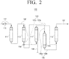
- FIG. 2 is an inside configuration map that briefly illustrates a water purification process of a water purifier according to an embodiment.
- the water purifier 100 includes the filter 110 including a plurality of filters, the water quality sensor 130 for measuring water quality of water supplied to the filter 110, and the flow path shifting valve 150 for shifting the flow path of the filter 110 for filtering water supplied to the filter 110 selectively using the direct-type water purification method or reverse osmosis water purification method.
- the filter 110 may include a pre-treatment filter 111, 113, the first filter 115, the second filter 117, and a post-treatment filter 119.
- the pre-treatment filters 111 and 113 may be composed of a sediment filter 111, which receives water from a water supply source and removes dust, debris, various floating materials through a fine filter in the size of about five micron and a pre-carbon filter 113 which removes chlorine components and chemicals harmful to the human body such as trihalomethanes (THM), a synthetic detergent, an insecticide, or the like, by using an adsorption method of activated carbon.
- THM trihalomethanes
- the first filter 115 may be composed of the hollow fiber membrane filter, nano trap filter, or the like, for removing fine contaminants.
- the second filter 117 may be composed of a reverse osmosis membrane filter 117 which is composed of a reverse osmosis membrane of 0.0001 micron for filtering not only heavy metals such as lead and arsenic but also sodium, various pathogens, or the like, and discharging the concentrated living water through a drain pipe 194.
- the post-treatment filter 119 may be composed of a post-carbon filter that is connected to the first filter 115 by a first water purifying line 195, and connected to the second filter 117 by a second water purifying line 193, for removing unpleasant taste, odor, coloring, or the like, included in water that passed through the first filter 115 and the second filter 117.
- the type or number of filters installed before or after the first and second filters 115 and 117 is not limited thereto.
- the pre-treatment filters 111 and 113 are respectively formed in the form of an independent cartridge, but the embodiment is not limited thereto, and the pre-treatment filters 111 and 113 may be formed of a composite filter having functions of two or more filters.
- the sediment filter 111 and the pre-carbon filter 113 may be configured as a single pre-treatment filter.
- the water quality sensor 130 may be installed in a water supply line 191 between the water supply source and the pre-treatment filters 111 and 113. To be specific, the water quality sensor 130 may be installed in the water supply line 191 between the water supply source and the sediment filter 111.
- the water quality sensor 130 measures the quality of water provided from the water supply source to the filter 110.
- the water purifier 100 may select a filter for supplying water according to the water quality value measured by the water quality sensor 130.
- the water supplied in accordance with the water quality value measured by the water quality sensor 130 may be selectively supplied to the first filter 115 or the second filter 117.
- the flow path shifting valve 150 may be installed at a point where a first water purifying line 195, between the pre-treatment filters 111 and 113 and the first filter 115, and a second water purifying line 193, between the pre-treatment filters 111 and 113 and the second filter 117, meet. Specifically, the flow path shifting valve 150 may be provided at a part at a lower end of the pre-carbon filter 113 where the second water purifying line 193 and the first water purifying line 195 are connected.
- the flow path shifting valve 150 may supply the water which passed the pre-treatment filters 111 and 113 to one side of the first filter 115 and the second filter 117 by the processor 170.
- the filter 110 may include a pre-treatment line 192 between the water supply line 191 and the first water purifying line 195 and the second water purifying line 193, through which water that passed at least one pre-treatment filter 111, 113 is discharged.
- the pre-treatment line 192 may filter the supplied water primarily.
- One side of the flow path shifting valve 150 may be connected to the pre-treatment line 192, and the other side thereof can be connected to the first water purifying line 195 and the second water purifying line 193, respectively.
- the flow path shifting valve 150 may switch the flow path to provide the water having passed through the pre-treatment filters 111 and 113 to the first filter 115 or the second filter 117 according to the measured water quality value.
- the flow path shifting valve 150 may shift the flow path so that the water that passed through the pre-treatment filters 111 and 113 flows to the first water purifying line 195 to be provided to the first filter 115.
- the flow path shifting valve 150 may shift the flow path so that the water that passed through the pre-treatment filters 111 and 113 flows to the second water purifying line 193 to be provided to the second filter 117.
- the first water purifying line 195 includes a first water purifying line front end 195a formed at the front end of the first filter 115 and a rear end 195b of the first water purifying line formed at the rear end of the first filter 115.
- the first water purifying line front end 195a is a flow path through which water passed through the pre-treatment filters 111 and 113 is supplied to the first filter 115
- the first water purifying line front end 195a is a flow path through which the water passing through the first filter 115 is provided to the post-treatment filter 119.
- the second water purifying line 193 includes a second water purifying line front end 193a formed at the front end of the second filter 117 and a second water purifying line rear end 193b formed at the rear end of the second filter 117.
- the second water purifying line front end 193a is a flow path through which water passed through the pre-treatment filters 111 and 113 is provided to the second filter 117
- the second water purifying line front end 193a is a flow path through which the water passing through the second filter 117 is provided to the post-treatment filter 119.
- the second filter 117 by the reverse osmosis water purification method has small flow rate and thus, by forming the second water purifying line rear end 193b in which the water which passed the second filter 117 flows to be long, flow rate of water collected in the second water purifying line 193 may be secured without including a separate water tank.
- the rear end 193b of the second water purifying line may be formed to be longer than a preset length in order to secure purified water that passed through the second filter 117, and the rear end 193b of the second water purifying line may be formed to be longer than the rear end 195b of the first water purifying line.
- the second water purifying line rear end 193b between the second filter 117 and the post-treatment filter 119 has been described as being long, it is not limited thereto, and the flow path through which the water having passed through the second filter 117 can be stored may be formed long.
- the water discharge line 197 formed at the rear end of the post-treatment filter 119 may be formed to be long, or the flow path connected to the cold/hot apparatus in the water discharge line 197 may be formed to be long.
- the filtered water from the second filter 117 is not drained from a water tank storing the separate purified water when the user presses the selection button to be drunken by the user, but the amount of water (about of 0.5 l) stored in the rear end 193b of the second water purifying line may be discharged through the water discharge line 197.
- the purified water can be directly supplied to the user even in the reverse osmosis water purification method passing through the second filter 117, thereby improving the hygiene. Since water can be stored in the second water purifying line 193 where water flows without using a separate water tank in which the purified water is stored, there is no concern for microbial contamination. In addition, unlike the water tank where a separate washing is required, the second water purifying line 193 can be cleaned by flowing the sterilized water therein, thereby facilitating washing and sterilization.
- Forming the flow path to be long may minimize the volume of the water purifier 100 rather than including a separate water tank and thus, the water purifier 100 of a compact structure may be provided.
- each of the first water purifying line 195 and the second water purifying line 193 may be connected to the flow path shifting valve 150, and the other end may be connected to the post-treatment filter 119.
- the rear end of post-treatment filter 119 may include the water discharge line 197 that supplies filtered water to the user.
- FIG. 3 is an inside configuration map that briefly illustrates a water purification process of a water purifier according to another embodiment.
- the water purifier 101 has mostly the same configuration as that of the water purifier 100 illustrated in FIG. 2 , except that the second water purifying line 193 of the filter 110 is arranged in a plurality of wound forms. Therefore, the water purifier 101 according to another embodiment will be described with reference to the different structure of the second water purifying line 193 and detailed description of the overlapped configuration that is the same as the water purifier 100 as illustrated in FIG. 2 will be omitted.
- the second water purifying line 193 includes the second water purifying line front end 193a formed at the front end of the second filter 117 and a second water purifying line rear end 193c formed at the rear end of the second filter 117.
- the second water purifying line front end 193a is a flow path through which water passed through the pre-treatment filters 111 and 113 is provided to the second filter 117
- the second water purifying line front end 193a is a flow path through which the water passing through the second filter 117 is provided to the post-treatment filter 119.
- the second water purifying line rear end 193c may be formed to be longer than a predetermined length in order to obtain the purified water passing through the second filter 117, and the second water purifying line rear end 193c may be formed to be longer than the first water purifying line rear end 195b.
- the second water purifying line rear end 193c may be arranged such that a part of an area of the second water purifying line rear end 193c for storing water that passed through the second filter 117 is in a plurality of wound forms.
- the water that passed through the second filter 117 may be stored in the second water purifying line rear end 193c that is wound in a plurality of times and thus, a separate water tank is not necessary and flow rate of water that is discharged in the second water purifying line 193 may be secured.
- the second water purifying line rear end 193c between the second filter 117 and the post-treatment filter 119 has been described as being arranged in a plurality of wound forms, but the embodiment is not limited thereto, and a plurality of wound areas may be formed in a flow path in which water than passed through the second filter 117 may be stored.
- FIG. 4 is an inside configuration map that briefly illustrates a water purification process of a water purifier according to still another embodiment.
- the water purifier 102 has mostly the same structure as the water purifier 100 illustrated in FIG. 2 , except that the flow sensors 141 and 142 are disposed in the first and second water purifying lines 195 and 193 of the filter 110, respectively. Accordingly, the water purifier 102 according to another embodiment will be described with respect to the structure in which the flow sensors 141 and 142 are disposed in the first and second water purifying lines 195 and 193, respectively, which is the different configuration, and overlapping configuration as the water purifier 100 as described in FIG. 2 will be omitted.
- the water purifier 102 may include the first flow sensor 141 for measuring an amount of water supplied to the first filter 115 and the second flow sensor 142 for measuring an amount of water supplied to the second filter 117.
- the first flow sensor 141 may be disposed in the first water purifying line 195, and specifically, may be disposed at the first water purifying line front end 195a. Since the first filter 115 is a direct-type water purification filter, the difference between the amount of water provided to the first filter 115 and the amount of water passing through the first filter 115 is small, so that the first flow sensor 141 can also be disposed at the rear end 195b of the first water purifying line.
- the second flow sensor 142 may be disposed in the second water purifying line 193, and may be specifically disposed at the second water purifying front end 193a. Since the second filter 117 is a reverse osmosis water purifying filter, a portion of the water passing through the second filter 117 is discharged through the drain pipe 194. Accordingly, the second flow sensor 142 may be disposed at the front end of the second filter 117 because the amount of water provided to the second filter 117 should be measured in order to measure the amount of water passing through the second filter 117.
- the water purifier 102 may include a notification device (not shown) for notifying the user of whether to replace a filter in the filter 110.
- Whether to replace the first filter 115 may be determined by the processor 170 through the amount of water passing through the first filter 115 measured by the first flow sensor 141, and whether the second filter 117 is replaced can be determined by the processor 170 through the amount of water passing through the second filter 117 measured by the second flow sensor 142.
- the processor 170 may generate a filter replacement notification signal when replacement of the first filter 115 or the second filter 117 is necessary.
- the notification device may guide the filter replacement to a user by receiving the filter replacement notification signal.
- the notification device may be configured as a device, such as a lighting, speaker, display, or the like.
- the notification device may be configured with communication technology (for example, near-field communication (NFC), etc.) to guide the user to filter replacement and to guide the user's mobile phone or guide the user's mobile phone to a dedicated application of the smartphone to enable the user's filter replacement order. Accordingly, the user can quickly respond to the need for replacement of the filter.
- NFC near-field communication
- the replacement timing of the first filter 115 and the second filter 117 is different from each other.
- the replacement timing of the first filter 115 is about 12 months and the replacement timing of the second filter 117 is about 24 months.
- the replacement timing of the first filter 115 and the second filter 117 is different so that if a consumer does not replace the filter, the water that is not filtered adequately may be discharged.
- the processor 170 can control the flow path shifting valve 150 so that water provided from the water supply source is supplied to only the second filter 117 when replacement of the first filter 115 is necessary.
- the water provided from the water supply source may be provided to the second filter 117 regardless of the measured water quality value. Since the life of the first filter 115 has been exhausted, water of which measured water quality value is less than a predetermined water quality value can also be filtered through the second filter 117.
- the processor 170 may not perform a water discharge command to discharge the purified water if the measured water quality value of the water provided from the water supply source is greater than the predetermined water quality value.
- Water having a water quality value greater than the predetermined water quality value must pass through the second filter 117 of the reverse osmosis type to provide purified water that satisfies a predetermined criterion. Therefore, if life of the second filter 117 is exhausted and the second filter 117 needs to be replaced, when water having a water quality value greater than a predetermined water quality value is supplied to the water purifier 102, the water purifier 100 can stop the supply of purified water.
- FIG. 5 is a flowchart illustrating a method for water purifying of a water purifier according to an embodiment.
- the water quality of the water supplied from the water supply source is measured by the water quality sensor 130 provided at the inlet end of the filter 110 in operation S510.
- the water quality value measured by the water quality sensor 130 is determined by considering at least one of turbidity or total dissolved solids (TDS).
- the water quality sensor 130 may be composed of the TDS sensor for measuring the conductivity of water.
- the supplied water is selectively provided to the first filter 115 with the direct-type water purification method or to the second filter 117 with the reverse osmosis water purification method.
- the water pollution level of water can be determined by comparing the water quality value measured by the water quality sensor 130 at the inlet end of the filter 110 with a predetermined water quality value. The higher the level of contamination of the water supplied from the water source, the higher the filtration performance of the filter is required.
- the preset water quality value can be set to the water quality value of the water quality of the tap water provided from the water supply source.
- the provided water is filtered by the first filter 115 in a direct-type water purification method. If the measured water quality value is greater than the predetermined water quality value, the provided water is filtered by the second filter 117 of the reverse osmosis water purification method.
- the water purifier 100 performs filtering by selecting a suitable filter according to the water quality of the water supplied to the filter 110. Accordingly, even when the groundwater containing the excess ions is introduced into the water purifier 100 or the harmful substance is introduced into the water purifier 100, such as when the water supply source is connected to an old pipe, the water purifier 100 may provide purified water that satisfies a predetermined criterion. That is, it is possible to maintain a predetermined filtering level regardless of the water being introduced.
- FIG. 6 is a flowchart illustrating a method for water purifying of a water purifier according to another embodiment.
- the amount of water supplied to the first filter 115 is measured by the first flow sensor 141 provided at the inlet end of the first filter 115, and the amount of water supplied to the second filter 117 from the second flow sensor 142 provided at the inlet end of the second filter 117 is measured in operation S610.
- the first filter 115 and the second filter 117 are different from each other in terms of the water purification method and thus, there may be a difference in the replacement timing. Accordingly, the amount of water introduced into each of the first filter 115 and the second filter 117 may be measured in order to determine the replacement timing of each of the first filter 115 and the second filter 117.
- Whether to replace the first filter 115 is determined based on the amount of water measured by the first flow sensor 141 at the inlet end of the first filter 115, and whether to replace the second filter 117 is determined based on the amount of water measured by the second flow sensor 142 at the inlet end of the second filter 117 in operation S620.
- the first reference value may be set to the allowable flow rate of the first filter 115.
- the second reference value may be set to the allowable flow rate of the second filter 117.
- the user can inform the user of the replacement of the first filter 115, and the water provided from the water supply source is provided only to the second filter 117 in operation S630.
- the output method of the filter replacement notification signal can output a message through a display, output an alarm sound through a speaker, or output both.
- the first filter 115 with the direct-type water purification method may be formed to have a shorter replacement timing than the second filter 117.
- the water purifier 100 may provide drinking water using the second filter 117.
- the second filter 117 with the reverse osmosis water purification method may perform a higher level of filtering than the first filter 115 and thus, water having a water quality value less than the predetermined water quality value may provide purified water that satisfies a predetermined criterion, even if the water is filtered by the second filter 117.
- the output method of the filter replacement notification signal can output a message through a display, output an alarm through a speaker, or output both.
- Water quality of water provided from the water supply source is measured in operation S651.
- the measured water quality value and the predetermined water quality value are compared in operation S652.
- water is provided to the first filter 115 as the basic control method of a water purifier in operation S653.
- the water purifier 100 can immediately discharge drinking water as the user presses a selection button of purified water such as cold water and hot water.
- a selection button of purified water such as cold water and hot water.
- the water discharge command is input to the water purifier 100.
- the second filter 117 needs to be replaced and the measured water quality value is greater than the predetermined water quality value, the water purifier may not operate to perform the water discharge command.
Landscapes
- Chemical & Material Sciences (AREA)
- Engineering & Computer Science (AREA)
- Water Supply & Treatment (AREA)
- Chemical Kinetics & Catalysis (AREA)
- Life Sciences & Earth Sciences (AREA)
- Nanotechnology (AREA)
- Hydrology & Water Resources (AREA)
- Organic Chemistry (AREA)
- Environmental & Geological Engineering (AREA)
- Electrochemistry (AREA)
- Biochemistry (AREA)
- General Health & Medical Sciences (AREA)
- General Physics & Mathematics (AREA)
- Immunology (AREA)
- Pathology (AREA)
- Analytical Chemistry (AREA)
- Health & Medical Sciences (AREA)
- Physics & Mathematics (AREA)
- Separation Using Semi-Permeable Membranes (AREA)
- Water Treatment By Sorption (AREA)
Claims (12)
- Wasserreiniger, umfassend:einen Wasserqualitätssensor (130), der dazu konfiguriert ist, einen Wasserqualitätswert von Wasser zu messen, das aus einer Wasserzufuhrquelle zugeführt wird, wobei der Wasserqualitätssensor (130) mindestens einen von einem Sensor für gesamte gelöste Feststoffe (TDS), einem Trübungssensor und einem Ionensensor umfasst und der Wasserqualitätswert der im Wasser enthaltenen Menge an Ionen oder der Trübung des Wassers entspricht;ein erstes Filter (115), das dazu konfiguriert ist, durch ein erstes Verfahren dem ersten Filter (115) zugeführtes Wasser zu filtrieren, um feine Verunreinigungen zu entfernen;ein zweites Filter (117), das dazu konfiguriert ist, durch ein zweites Verfahren, das sich von dem ersten Verfahren unterscheidet, dem zweiten Filter (117) zugeführtes Wasser zu filtrieren;eine erste Wasserreinigungsleitung (195), die ein vorderes Ende (195a) der ersten Wasserreinigungsleitung, das am vorderen Ende des ersten Filters (115) ausgebildet ist, und ein hinteres Ende (195b) der ersten Wasserreinigungsleitung, das am hinteren Ende des ersten Filters (115) zwischen dem ersten Filter (115) und einer Wasserableitung (197) ausgebildet ist, einschließt, um das durch das erste Filter (115) filtrierte Wasser der Wasserableitung (197) bereitzustellen;eine zweite Wasserreinigungsleitung (193), die ein vorderes Ende (193a) der zweiten Wasserreinigungsleitung, das am vorderen Ende des zweiten Filters (117) ausgebildet ist, und ein hinteres Ende (193b) der zweiten Wasserreinigungsleitung, das am hinteren Ende des zweiten Filters (117) zwischen dem zweiten Filter (117) und der Wasserableitung (197) ausgebildet ist, einschließt, um das durch das zweite Filter (117) filtrierte Wasser der Wasserableitung (197) bereitzustellen;ein Strömungsweg-Umschaltventil (150), das dazu konfiguriert ist, so gesteuert zu werden, dass es Wasser, das aus der Wasserzufuhrquelle zugeführt wird, selektiv nur einem von dem ersten Filter (115) über das vordere Ende (195a) der ersten Wasserreinigungsleitung und dem zweiten Filter (117) über das vordere Ende (193a) der zweiten Wasserreinigungsleitung zuführt; undeinen Prozessor (170), der dazu konfiguriert ist, das Strömungsweg-Umschaltventil (150) auf Grundlage des durch den Sensor (130) gemessenen Wasserqualitätswerts zu steuern,wobei das erste Verfahren ein Wasserreinigungsverfahren vom direkten Typ ist, gemäß dem das erste Filter (115) direkt mit der Verwendungsstelle verbunden ist, sodass das durch das erste Filter (115) filtrierte Wasser direkt einem Benutzer zugeführt werden kann, ohne zuerst in einem Wasserspeichertank gespeichert werden zu müssen, und das zweite Verfahren ein Umkehrosmose-Wasserreinigungsverfahren ist, undwobei der Prozessor (170) ferner dazu konfiguriert ist, das Strömungsweg-Umschaltventil (150) so zu steuern, dass es auf Grundlage davon, dass der gemessene Wasserqualitätswert kleiner als ein vorbestimmter Wasserqualitätswert ist, das aus der Wasserzufuhrquelle zugeführte Wasser dem vorderen Ende (195a) der ersten Wasserreinigungsleitung, dem ersten Filter (115), dem hinteren Ende (195b) der ersten Wasserreinigungsleitung und der Wasserableitung (197) zuführt und auf Grundlage davon, dass der Wasserqualitätswert größer als der vorbestimmte Wasserqualitätswert ist, das aus der Wasserzufuhrquelle zugeführte Wasser dem vorderen Ende (193a) der zweiten Wasserreinigungsleitung, dem zweiten Filter (117), dem hinteren Ende (193b) der zweiten Wasserreinigungsleitung und der Wasserableitung (197) zuführt.
- Wasserreiniger nach Anspruch 1,
wobei das hintere Ende (193b) der zweiten Wasserreinigungsleitung länger als das hintere Ende (195b) der ersten Wasserreinigungsleitung ist. - Wasserreiniger nach Anspruch 2, wobei das hintere Ende (193b) der zweiten Wasserreinigungsleitung eine Vielzahl von Malen gewickelt ist.
- Wasserreiniger nach Anspruch 1, wobei der Wasserqualitätssensor dazu konfiguriert ist, die elektrische Leitfähigkeit des aus der Wasserzufuhrquelle zugeführten Wassers zu messen, um dadurch den Wasserqualitätswert des aus der Wasserzufuhrquelle zugeführten Wassers zu messen.
- Wasserreiniger nach Anspruch 1, ferner umfassend:ein Vorbehandlungsfilter (111, 113), das dazu konfiguriert ist, das aus der Wasserzufuhrquelle zugeführte Wasser aufzunehmen und dann zu filtrieren, bevor es selektiv durch das Strömungsweg-Umschaltventil dem ersten Filter oder dem zweiten Filter zugeführt wird; undein Nachbehandlungsfilter (119), das dazu konfiguriert ist, das durch das erste Filter filtrierte Wasser und das durch das zweite Filter filtrierte Wasser aufzunehmen und dann zu filtrieren.
- Wasserreiniger nach Anspruch 5, wobei das Strömungsweg-Umschaltventil dazu konfiguriert ist, das durch das Vorbehandlungsfilter filtrierte Wasser selektiv nur einem von dem ersten Filter oder dem zweiten Filter zuzuführen.
- Wasserreiniger nach Anspruch 5, wobei der Wasserqualitätssensor dazu konfiguriert ist, den Wasserqualitätswert von Wasser zu messen, das aus der Wasserzufuhrquelle zugeführt wird, bevor es durch das Vorbehandlungsfilter aufgenommen wird.
- Wasserreiniger nach Anspruch 1, ferner umfassend:einen ersten Strömungssensor (141), der dazu konfiguriert ist, eine Menge des Wassers zu messen, das dem ersten Filter zugeführt wird; undeinen zweiten Strömungssensor (142), der dazu konfiguriert ist, eine Menge des Wassers zu messen, das dem zweiten Filter zugeführt wird.
- Wasserreiniger nach Anspruch 8, wobei der Prozessor ferner dazu konfiguriert ist, auf Grundlage der durch den ersten Strömungssensor gemessenen Menge an Wasser zu bestimmen, ob das erste Filter ausgetauscht werden soll, und auf Grundlage der durch den zweiten Strömungssensor gemessenen Menge an Wasser zu bestimmen, ob das zweite Filter ausgetauscht werden soll.
- Wasserreiniger nach Anspruch 9, wobei der Prozessor ferner dazu konfiguriert ist, auf Grundlage davon, dass bestimmt wird, dass das erste Filter ausgetauscht werden soll, ein Filteraustausch-Benachrichtigungssignal zu generieren und das Strömungsweg-Umschaltventil so zu steuern, dass es das aus der Wasserzufuhrquelle zugeführte Wasser dem zweiten Filter und nicht dem ersten Filter zuführt.
- Wasserreiniger nach Anspruch 9, wobei der Prozessor ferner zu Folgendem konfiguriert ist:auf Grundlage davon, dass bestimmt wird, dass das zweite Filter ausgetauscht werden soll, ein Filteraustausch-Benachrichtigungssignal zu generieren, undauf Grundlage davon, dass bestimmt wird, dass das zweite Filter ausgetauscht werden soll und der gemessene Wasserqualitätswert größer als ein vorbestimmter Wasserqualitätswert ist, so zu steuern, dass kein Wasserablassbefehl durchgeführt wird, um gereinigtes Wasser abzulassen.
- Verfahren zum Steuern des Wasserreinigers nach einem der Ansprüche 1 bis 11, wobei das Verfahren Folgendes umfasst:Messen eines Wasserqualitätswerts von Wasser, das dem Wasserreiniger aus einer Wasserzufuhrquelle zugeführt wird, unter Verwendung des Wasserqualitätssensors (130) des Wasserreinigers, wobei der Wasserqualitätswert der im Wasser enthaltenen Menge an Ionen oder der Trübung des Wassers entspricht; undselektives Zuführen des aus der Wasserzufuhrquelle zugeführten Wassers nur einem von dem ersten Filter (115), um feine Verunreinigungen zu entfernen, und dem zweiten Filter (117) auf Grundlage des gemessenen Wasserqualitätswerts,wobei das erste Verfahren ein Wasserreinigungsverfahren vom direkten Typ ist, gemäß dem das erste Filter (115) direkt mit der Verwendungsstelle verbunden ist, sodass das durch das erste Filter (115) filtrierte Wasser direkt einem Benutzer zugeführt werden kann, ohne zuerst in einem Wasserspeichertank gespeichert werden zu müssen, und sich das zweite Verfahren von dem ersten Verfahren unterscheidet und ein Umkehrosmose-Wasserreinigungsverfahren ist, undwobei der Prozessor (170) das Strömungsweg-Umschaltventil (150) auf Grundlage des durch den Sensor (130) gemessenen Wasserqualitätswerts so steuert, dass:
das Wasser aus der Wasserzufuhrquelle dem vorderen Ende (195a) der ersten Wasserreinigungsleitung, dem ersten Filter (115), dem hinteren Ende (195b) der ersten Wasserreinigungsleitung und der Wasserableitung (197) zugeführt wird, wenn der gemessene Wasserqualitätswert kleiner als ein vorbestimmter Wasserqualitätswert ist, und das Wasser aus der Wasserzufuhrquelle dem vorderen Ende (193a) der zweiten Wasserreinigungsleitung, dem zweiten Filter (117), dem hinteren Ende (193b) der zweiten Wasserreinigungsleitung und der Wasserableitung (197) zugeführt wird, wenn der Wasserqualitätswert größer als der vorbestimmte Wasserqualitätswert ist.
Applications Claiming Priority (1)
| Application Number | Priority Date | Filing Date | Title |
|---|---|---|---|
| KR1020180156682A KR102934705B1 (ko) | 2018-12-07 | 2018-12-07 | 정수기 및 이의 제어 방법 |
Publications (2)
| Publication Number | Publication Date |
|---|---|
| EP3663266A1 EP3663266A1 (de) | 2020-06-10 |
| EP3663266B1 true EP3663266B1 (de) | 2022-08-03 |
Family
ID=68771558
Family Applications (1)
| Application Number | Title | Priority Date | Filing Date |
|---|---|---|---|
| EP19213617.4A Active EP3663266B1 (de) | 2018-12-07 | 2019-12-04 | Wasserreiniger und steuerungsverfahren dafür |
Country Status (5)
| Country | Link |
|---|---|
| US (1) | US11292732B2 (de) |
| EP (1) | EP3663266B1 (de) |
| KR (1) | KR102934705B1 (de) |
| CN (1) | CN113015690B (de) |
| WO (1) | WO2020116884A1 (de) |
Families Citing this family (4)
| Publication number | Priority date | Publication date | Assignee | Title |
|---|---|---|---|---|
| CN112875805A (zh) * | 2021-01-15 | 2021-06-01 | 珠海格力电器股份有限公司 | 一种水处理方法、装置、电子设备及存储介质 |
| EP4475976A4 (de) * | 2022-02-09 | 2026-02-25 | Cloud Water Filter Llc | Wasserfiltrationssystem und zugehöriges verfahren |
| KR102518322B1 (ko) * | 2022-03-31 | 2023-04-05 | (주)디이산업 | 실시간 상수도 수질감지 및 수질사고 대응 시스템 및 그것의 동작방법 |
| WO2023220431A1 (en) * | 2022-05-13 | 2023-11-16 | Cloud Water Filter, LLC | Water filtration system, and associated method |
Family Cites Families (34)
| Publication number | Priority date | Publication date | Assignee | Title |
|---|---|---|---|---|
| US5132017A (en) * | 1990-01-16 | 1992-07-21 | Teledyne Industries, Inc. | Reverse osmosis system |
| JP2765813B2 (ja) * | 1994-11-14 | 1998-06-18 | 三星電子株式会社 | 浄水器の漏水感知装置 |
| CN1162569A (zh) * | 1996-04-17 | 1997-10-22 | 三星电子株式会社 | 净水器的净水效率显示装置 |
| JP3813338B2 (ja) * | 1997-12-09 | 2006-08-23 | オルガノ株式会社 | 水濾過装置および水中の病原性微生物除去方法 |
| KR100278516B1 (ko) * | 1998-08-11 | 2001-02-01 | 정휘동 | 정수장치 |
| KR20030062838A (ko) * | 2002-01-21 | 2003-07-28 | 정휘동 | 수질 및 유량측정이 가능한 역삼투압 정수기 |
| KR200298701Y1 (ko) * | 2002-09-16 | 2002-12-27 | 조신행 | 필터교환표시기능을 갖는 정수기 |
| US7632410B2 (en) * | 2003-08-21 | 2009-12-15 | Christopher Heiss | Universal water purification system |
| KR20050079680A (ko) * | 2004-02-06 | 2005-08-11 | 이순세 | 제거수 재활용 구조를 갖는 중대형 역삼투압 정수장치 |
| US20080023400A1 (en) * | 2006-07-27 | 2008-01-31 | Kloos Steven D | Water treatment system and method with a continuous partial flow bypass path |
| KR100844529B1 (ko) * | 2007-02-27 | 2008-07-08 | 웅진코웨이주식회사 | 축열조를 포함하는 정수기 |
| US20100264073A1 (en) * | 2008-04-01 | 2010-10-21 | Min Chien Teng | Water-purifying device for increasing oxygen content |
| CN102301193A (zh) * | 2009-02-02 | 2011-12-28 | Lg电子株式会社 | 冰箱 |
| US20100224558A1 (en) * | 2009-03-09 | 2010-09-09 | Jack Barker | Water Filtration System |
| US20130313191A1 (en) | 2009-05-14 | 2013-11-28 | Omni Water Solutions, Inc. | Water treatment systems and methods |
| JP2011161337A (ja) * | 2010-02-05 | 2011-08-25 | New Medica Tech Corp | 浄水器のフィルター洗浄システム |
| US20130032540A1 (en) * | 2010-03-04 | 2013-02-07 | Terragroup Corporation | Lightweight modular water purification system with reconfigurable pump power options |
| EP2571594B1 (de) | 2010-05-19 | 2020-02-19 | Woongjin Coway Co., Ltd. | Wasseraufbereitungsvorrichtung sowie sterilisierungs- und reinigungsverfahren dafür |
| KR20110127588A (ko) | 2010-05-19 | 2011-11-25 | 웅진코웨이주식회사 | 살균 정수기 |
| JP2011255349A (ja) | 2010-06-11 | 2011-12-22 | Panasonic Electric Works Co Ltd | 水処理装置 |
| KR20120003194A (ko) * | 2010-07-02 | 2012-01-10 | 웅진코웨이주식회사 | 정수장치 및 그의 용존물 농도 제어 방법 |
| JP2012217867A (ja) * | 2011-04-04 | 2012-11-12 | Hitachi Plant Technologies Ltd | 飲料水供給システム |
| KR101421155B1 (ko) * | 2012-04-23 | 2014-07-22 | 주식회사 피코그램 | 밀폐형 냉수탱크 및 이를 이용한 냉수,정수시스템 |
| KR101210872B1 (ko) * | 2012-05-31 | 2012-12-12 | 주식회사 포스코건설 | 수질 변동에 적용가능한 막여과 정수장치 |
| JP2015036133A (ja) * | 2013-08-12 | 2015-02-23 | 住友電気工業株式会社 | バラスト水濾過装置及びバラスト水処理システム |
| SI24500A (sl) * | 2013-10-11 | 2015-04-30 | Leu D.O.O. | Mobilni sistem za čiščenje in pripravo pitne vode, kemijski multimedijski filter in delovanje le-tega |
| KR20160008308A (ko) | 2014-07-14 | 2016-01-22 | 코웨이 주식회사 | 수처리 시스템 및 방법 |
| CN107073369A (zh) * | 2014-09-11 | 2017-08-18 | 三菱重工业株式会社 | 水处理装置以及水处理方法 |
| CN205216585U (zh) * | 2015-10-29 | 2016-05-11 | 北京碧水源膜科技有限公司 | 一种纳滤膜tds调节系统 |
| WO2017165984A1 (fr) | 2016-03-29 | 2017-10-05 | Sonatec-Inter Sàrl | Procédé et dispositif de régulation de la dureté de l'eau pour une habitation |
| KR101991442B1 (ko) * | 2016-04-11 | 2019-06-20 | 엘지전자 주식회사 | 정수기 |
| US20180111070A1 (en) * | 2016-10-25 | 2018-04-26 | Ds Services Of America, Inc. | Bypass for high demand periods for water purification system |
| CN107042055B (zh) * | 2017-06-28 | 2020-08-18 | 苏州华商新能源有限公司 | 一种废气处理系统 |
| CN107522308A (zh) * | 2017-10-13 | 2017-12-29 | 朱平 | 一种智能纯水机 |
-
2018
- 2018-12-07 KR KR1020180156682A patent/KR102934705B1/ko active Active
-
2019
- 2019-12-03 WO PCT/KR2019/016891 patent/WO2020116884A1/en not_active Ceased
- 2019-12-03 CN CN201980074766.5A patent/CN113015690B/zh active Active
- 2019-12-04 EP EP19213617.4A patent/EP3663266B1/de active Active
- 2019-12-06 US US16/705,745 patent/US11292732B2/en active Active
Also Published As
| Publication number | Publication date |
|---|---|
| KR102934705B1 (ko) | 2026-03-06 |
| CN113015690B (zh) | 2024-03-08 |
| US20200180980A1 (en) | 2020-06-11 |
| US11292732B2 (en) | 2022-04-05 |
| EP3663266A1 (de) | 2020-06-10 |
| WO2020116884A1 (en) | 2020-06-11 |
| KR20200069536A (ko) | 2020-06-17 |
| CN113015690A (zh) | 2021-06-22 |
Similar Documents
| Publication | Publication Date | Title |
|---|---|---|
| US11292732B2 (en) | Water purifier and control method of the same | |
| US20170129795A1 (en) | Reverse osmosis water purifier | |
| Konieczny et al. | Using activated carbon to improve natural water treatment by porous membranes | |
| JP6441808B2 (ja) | 淡水化装置及び淡水化方法 | |
| KR20120078611A (ko) | 수처리 장치 및 이를 이용한 수처리 방법 | |
| JP6194887B2 (ja) | 淡水製造方法 | |
| WO2011045998A1 (ja) | 浄水器 | |
| US20060096920A1 (en) | System and method for conditioning water | |
| CN113402084A (zh) | 一种净水装置 | |
| JP2005279614A (ja) | 浄水装置 | |
| JP4427362B2 (ja) | 上水配水管理システム | |
| JPWO2017159303A1 (ja) | 高硬度排水の処理方法 | |
| KR101866981B1 (ko) | 정수기 | |
| CN212609718U (zh) | 家用净水装置及厨下式净水机 | |
| JP2012217867A (ja) | 飲料水供給システム | |
| JP2010201335A (ja) | 水処理システム及び水処理方法 | |
| Jang et al. | Performance of ultrafiltration membrane process combined with coagulation/sedimentation | |
| JP2009183920A (ja) | 液体浄化装置 | |
| EP1553055A1 (de) | Vorrichtung und Verfahren zur Wasserreinigung | |
| JP2007000727A (ja) | 膜分離活性汚泥処理装置の運転方法 | |
| CN111344257A (zh) | 用于分配具有一致味道的水的水分配装置 | |
| KR102147158B1 (ko) | 용존이온 농도에 기초한 역세수의 선택기능을 갖는 막여과 수처리장치 및 그 제어방법 | |
| KR20150039194A (ko) | 플러싱 기능을 가지는 정수기 및 이를 제어하는 제어방법 | |
| WO2007130053A1 (en) | System and method for conditioning water | |
| CN206645913U (zh) | 一种纳米级碳化硅陶瓷膜净化器 |
Legal Events
| Date | Code | Title | Description |
|---|---|---|---|
| PUAI | Public reference made under article 153(3) epc to a published international application that has entered the european phase |
Free format text: ORIGINAL CODE: 0009012 |
|
| STAA | Information on the status of an ep patent application or granted ep patent |
Free format text: STATUS: THE APPLICATION HAS BEEN PUBLISHED |
|
| AK | Designated contracting states |
Kind code of ref document: A1 Designated state(s): AL AT BE BG CH CY CZ DE DK EE ES FI FR GB GR HR HU IE IS IT LI LT LU LV MC MK MT NL NO PL PT RO RS SE SI SK SM TR |
|
| AX | Request for extension of the european patent |
Extension state: BA ME |
|
| STAA | Information on the status of an ep patent application or granted ep patent |
Free format text: STATUS: REQUEST FOR EXAMINATION WAS MADE |
|
| 17P | Request for examination filed |
Effective date: 20200724 |
|
| RBV | Designated contracting states (corrected) |
Designated state(s): AL AT BE BG CH CY CZ DE DK EE ES FI FR GB GR HR HU IE IS IT LI LT LU LV MC MK MT NL NO PL PT RO RS SE SI SK SM TR |
|
| STAA | Information on the status of an ep patent application or granted ep patent |
Free format text: STATUS: EXAMINATION IS IN PROGRESS |
|
| 17Q | First examination report despatched |
Effective date: 20200914 |
|
| RIC1 | Information provided on ipc code assigned before grant |
Ipc: C02F 1/44 20060101ALN20220119BHEP Ipc: C02F 1/28 20060101ALN20220119BHEP Ipc: C02F 1/00 20060101AFI20220119BHEP |
|
| GRAP | Despatch of communication of intention to grant a patent |
Free format text: ORIGINAL CODE: EPIDOSNIGR1 |
|
| STAA | Information on the status of an ep patent application or granted ep patent |
Free format text: STATUS: GRANT OF PATENT IS INTENDED |
|
| RIC1 | Information provided on ipc code assigned before grant |
Ipc: C02F 1/44 20060101ALN20220207BHEP Ipc: C02F 1/28 20060101ALN20220207BHEP Ipc: C02F 1/00 20060101AFI20220207BHEP |
|
| INTG | Intention to grant announced |
Effective date: 20220225 |
|
| GRAS | Grant fee paid |
Free format text: ORIGINAL CODE: EPIDOSNIGR3 |
|
| GRAA | (expected) grant |
Free format text: ORIGINAL CODE: 0009210 |
|
| STAA | Information on the status of an ep patent application or granted ep patent |
Free format text: STATUS: THE PATENT HAS BEEN GRANTED |
|
| AK | Designated contracting states |
Kind code of ref document: B1 Designated state(s): AL AT BE BG CH CY CZ DE DK EE ES FI FR GB GR HR HU IE IS IT LI LT LU LV MC MK MT NL NO PL PT RO RS SE SI SK SM TR |
|
| REG | Reference to a national code |
Ref country code: AT Ref legal event code: REF Ref document number: 1508609 Country of ref document: AT Kind code of ref document: T Effective date: 20220815 Ref country code: CH Ref legal event code: EP |
|
| REG | Reference to a national code |
Ref country code: DE Ref legal event code: R096 Ref document number: 602019017732 Country of ref document: DE |
|
| REG | Reference to a national code |
Ref country code: IE Ref legal event code: FG4D |
|
| REG | Reference to a national code |
Ref country code: LT Ref legal event code: MG9D |
|
| REG | Reference to a national code |
Ref country code: NL Ref legal event code: MP Effective date: 20220803 |
|
| PG25 | Lapsed in a contracting state [announced via postgrant information from national office to epo] |
Ref country code: SE Free format text: LAPSE BECAUSE OF FAILURE TO SUBMIT A TRANSLATION OF THE DESCRIPTION OR TO PAY THE FEE WITHIN THE PRESCRIBED TIME-LIMIT Effective date: 20220803 Ref country code: RS Free format text: LAPSE BECAUSE OF FAILURE TO SUBMIT A TRANSLATION OF THE DESCRIPTION OR TO PAY THE FEE WITHIN THE PRESCRIBED TIME-LIMIT Effective date: 20220803 Ref country code: PT Free format text: LAPSE BECAUSE OF FAILURE TO SUBMIT A TRANSLATION OF THE DESCRIPTION OR TO PAY THE FEE WITHIN THE PRESCRIBED TIME-LIMIT Effective date: 20221205 Ref country code: NO Free format text: LAPSE BECAUSE OF FAILURE TO SUBMIT A TRANSLATION OF THE DESCRIPTION OR TO PAY THE FEE WITHIN THE PRESCRIBED TIME-LIMIT Effective date: 20221103 Ref country code: NL Free format text: LAPSE BECAUSE OF FAILURE TO SUBMIT A TRANSLATION OF THE DESCRIPTION OR TO PAY THE FEE WITHIN THE PRESCRIBED TIME-LIMIT Effective date: 20220803 Ref country code: LV Free format text: LAPSE BECAUSE OF FAILURE TO SUBMIT A TRANSLATION OF THE DESCRIPTION OR TO PAY THE FEE WITHIN THE PRESCRIBED TIME-LIMIT Effective date: 20220803 Ref country code: LT Free format text: LAPSE BECAUSE OF FAILURE TO SUBMIT A TRANSLATION OF THE DESCRIPTION OR TO PAY THE FEE WITHIN THE PRESCRIBED TIME-LIMIT Effective date: 20220803 Ref country code: FI Free format text: LAPSE BECAUSE OF FAILURE TO SUBMIT A TRANSLATION OF THE DESCRIPTION OR TO PAY THE FEE WITHIN THE PRESCRIBED TIME-LIMIT Effective date: 20220803 Ref country code: ES Free format text: LAPSE BECAUSE OF FAILURE TO SUBMIT A TRANSLATION OF THE DESCRIPTION OR TO PAY THE FEE WITHIN THE PRESCRIBED TIME-LIMIT Effective date: 20220803 |
|
| REG | Reference to a national code |
Ref country code: AT Ref legal event code: MK05 Ref document number: 1508609 Country of ref document: AT Kind code of ref document: T Effective date: 20220803 |
|
| PG25 | Lapsed in a contracting state [announced via postgrant information from national office to epo] |
Ref country code: PL Free format text: LAPSE BECAUSE OF FAILURE TO SUBMIT A TRANSLATION OF THE DESCRIPTION OR TO PAY THE FEE WITHIN THE PRESCRIBED TIME-LIMIT Effective date: 20220803 Ref country code: IS Free format text: LAPSE BECAUSE OF FAILURE TO SUBMIT A TRANSLATION OF THE DESCRIPTION OR TO PAY THE FEE WITHIN THE PRESCRIBED TIME-LIMIT Effective date: 20221203 Ref country code: HR Free format text: LAPSE BECAUSE OF FAILURE TO SUBMIT A TRANSLATION OF THE DESCRIPTION OR TO PAY THE FEE WITHIN THE PRESCRIBED TIME-LIMIT Effective date: 20220803 Ref country code: GR Free format text: LAPSE BECAUSE OF FAILURE TO SUBMIT A TRANSLATION OF THE DESCRIPTION OR TO PAY THE FEE WITHIN THE PRESCRIBED TIME-LIMIT Effective date: 20221104 |
|
| PG25 | Lapsed in a contracting state [announced via postgrant information from national office to epo] |
Ref country code: SM Free format text: LAPSE BECAUSE OF FAILURE TO SUBMIT A TRANSLATION OF THE DESCRIPTION OR TO PAY THE FEE WITHIN THE PRESCRIBED TIME-LIMIT Effective date: 20220803 Ref country code: RO Free format text: LAPSE BECAUSE OF FAILURE TO SUBMIT A TRANSLATION OF THE DESCRIPTION OR TO PAY THE FEE WITHIN THE PRESCRIBED TIME-LIMIT Effective date: 20220803 Ref country code: DK Free format text: LAPSE BECAUSE OF FAILURE TO SUBMIT A TRANSLATION OF THE DESCRIPTION OR TO PAY THE FEE WITHIN THE PRESCRIBED TIME-LIMIT Effective date: 20220803 Ref country code: CZ Free format text: LAPSE BECAUSE OF FAILURE TO SUBMIT A TRANSLATION OF THE DESCRIPTION OR TO PAY THE FEE WITHIN THE PRESCRIBED TIME-LIMIT Effective date: 20220803 Ref country code: AT Free format text: LAPSE BECAUSE OF FAILURE TO SUBMIT A TRANSLATION OF THE DESCRIPTION OR TO PAY THE FEE WITHIN THE PRESCRIBED TIME-LIMIT Effective date: 20220803 |
|
| REG | Reference to a national code |
Ref country code: DE Ref legal event code: R097 Ref document number: 602019017732 Country of ref document: DE |
|
| PG25 | Lapsed in a contracting state [announced via postgrant information from national office to epo] |
Ref country code: SK Free format text: LAPSE BECAUSE OF FAILURE TO SUBMIT A TRANSLATION OF THE DESCRIPTION OR TO PAY THE FEE WITHIN THE PRESCRIBED TIME-LIMIT Effective date: 20220803 Ref country code: EE Free format text: LAPSE BECAUSE OF FAILURE TO SUBMIT A TRANSLATION OF THE DESCRIPTION OR TO PAY THE FEE WITHIN THE PRESCRIBED TIME-LIMIT Effective date: 20220803 |
|
| PLBE | No opposition filed within time limit |
Free format text: ORIGINAL CODE: 0009261 |
|
| STAA | Information on the status of an ep patent application or granted ep patent |
Free format text: STATUS: NO OPPOSITION FILED WITHIN TIME LIMIT |
|
| PG25 | Lapsed in a contracting state [announced via postgrant information from national office to epo] |
Ref country code: AL Free format text: LAPSE BECAUSE OF FAILURE TO SUBMIT A TRANSLATION OF THE DESCRIPTION OR TO PAY THE FEE WITHIN THE PRESCRIBED TIME-LIMIT Effective date: 20220803 |
|
| 26N | No opposition filed |
Effective date: 20230504 |
|
| REG | Reference to a national code |
Ref country code: CH Ref legal event code: PL |
|
| REG | Reference to a national code |
Ref country code: BE Ref legal event code: MM Effective date: 20221231 |
|
| PG25 | Lapsed in a contracting state [announced via postgrant information from national office to epo] |
Ref country code: SI Free format text: LAPSE BECAUSE OF FAILURE TO SUBMIT A TRANSLATION OF THE DESCRIPTION OR TO PAY THE FEE WITHIN THE PRESCRIBED TIME-LIMIT Effective date: 20220803 Ref country code: LU Free format text: LAPSE BECAUSE OF NON-PAYMENT OF DUE FEES Effective date: 20221204 |
|
| PG25 | Lapsed in a contracting state [announced via postgrant information from national office to epo] |
Ref country code: LI Free format text: LAPSE BECAUSE OF NON-PAYMENT OF DUE FEES Effective date: 20221231 Ref country code: IE Free format text: LAPSE BECAUSE OF NON-PAYMENT OF DUE FEES Effective date: 20221204 Ref country code: CH Free format text: LAPSE BECAUSE OF NON-PAYMENT OF DUE FEES Effective date: 20221231 |
|
| PG25 | Lapsed in a contracting state [announced via postgrant information from national office to epo] |
Ref country code: FR Free format text: LAPSE BECAUSE OF NON-PAYMENT OF DUE FEES Effective date: 20221231 Ref country code: BE Free format text: LAPSE BECAUSE OF NON-PAYMENT OF DUE FEES Effective date: 20221231 |
|
| PG25 | Lapsed in a contracting state [announced via postgrant information from national office to epo] |
Ref country code: HU Free format text: LAPSE BECAUSE OF FAILURE TO SUBMIT A TRANSLATION OF THE DESCRIPTION OR TO PAY THE FEE WITHIN THE PRESCRIBED TIME-LIMIT; INVALID AB INITIO Effective date: 20191204 |
|
| PG25 | Lapsed in a contracting state [announced via postgrant information from national office to epo] |
Ref country code: CY Free format text: LAPSE BECAUSE OF FAILURE TO SUBMIT A TRANSLATION OF THE DESCRIPTION OR TO PAY THE FEE WITHIN THE PRESCRIBED TIME-LIMIT Effective date: 20220803 |
|
| PG25 | Lapsed in a contracting state [announced via postgrant information from national office to epo] |
Ref country code: MK Free format text: LAPSE BECAUSE OF FAILURE TO SUBMIT A TRANSLATION OF THE DESCRIPTION OR TO PAY THE FEE WITHIN THE PRESCRIBED TIME-LIMIT Effective date: 20220803 Ref country code: IT Free format text: LAPSE BECAUSE OF FAILURE TO SUBMIT A TRANSLATION OF THE DESCRIPTION OR TO PAY THE FEE WITHIN THE PRESCRIBED TIME-LIMIT Effective date: 20220803 |
|
| PG25 | Lapsed in a contracting state [announced via postgrant information from national office to epo] |
Ref country code: MC Free format text: LAPSE BECAUSE OF FAILURE TO SUBMIT A TRANSLATION OF THE DESCRIPTION OR TO PAY THE FEE WITHIN THE PRESCRIBED TIME-LIMIT Effective date: 20220803 |
|
| PG25 | Lapsed in a contracting state [announced via postgrant information from national office to epo] |
Ref country code: MC Free format text: LAPSE BECAUSE OF FAILURE TO SUBMIT A TRANSLATION OF THE DESCRIPTION OR TO PAY THE FEE WITHIN THE PRESCRIBED TIME-LIMIT Effective date: 20220803 |
|
| PG25 | Lapsed in a contracting state [announced via postgrant information from national office to epo] |
Ref country code: BG Free format text: LAPSE BECAUSE OF FAILURE TO SUBMIT A TRANSLATION OF THE DESCRIPTION OR TO PAY THE FEE WITHIN THE PRESCRIBED TIME-LIMIT Effective date: 20220803 |
|
| PG25 | Lapsed in a contracting state [announced via postgrant information from national office to epo] |
Ref country code: MT Free format text: LAPSE BECAUSE OF FAILURE TO SUBMIT A TRANSLATION OF THE DESCRIPTION OR TO PAY THE FEE WITHIN THE PRESCRIBED TIME-LIMIT Effective date: 20220803 |
|
| PG25 | Lapsed in a contracting state [announced via postgrant information from national office to epo] |
Ref country code: TR Free format text: LAPSE BECAUSE OF FAILURE TO SUBMIT A TRANSLATION OF THE DESCRIPTION OR TO PAY THE FEE WITHIN THE PRESCRIBED TIME-LIMIT Effective date: 20220803 |
|
| PGFP | Annual fee paid to national office [announced via postgrant information from national office to epo] |
Ref country code: DE Payment date: 20251120 Year of fee payment: 7 |
|
| PGFP | Annual fee paid to national office [announced via postgrant information from national office to epo] |
Ref country code: GB Payment date: 20251120 Year of fee payment: 7 |