EP3663074A1 - Verfahren zur additiven fertigung von formkörpern - Google Patents
Verfahren zur additiven fertigung von formkörpern Download PDFInfo
- Publication number
- EP3663074A1 EP3663074A1 EP18209713.9A EP18209713A EP3663074A1 EP 3663074 A1 EP3663074 A1 EP 3663074A1 EP 18209713 A EP18209713 A EP 18209713A EP 3663074 A1 EP3663074 A1 EP 3663074A1
- Authority
- EP
- European Patent Office
- Prior art keywords
- frame
- molded body
- shaped body
- connections
- built
- Prior art date
- Legal status (The legal status is an assumption and is not a legal conclusion. Google has not performed a legal analysis and makes no representation as to the accuracy of the status listed.)
- Granted
Links
Images


Classifications
-
- B—PERFORMING OPERATIONS; TRANSPORTING
- B29—WORKING OF PLASTICS; WORKING OF SUBSTANCES IN A PLASTIC STATE IN GENERAL
- B29C—SHAPING OR JOINING OF PLASTICS; SHAPING OF MATERIAL IN A PLASTIC STATE, NOT OTHERWISE PROVIDED FOR; AFTER-TREATMENT OF THE SHAPED PRODUCTS, e.g. REPAIRING
- B29C64/00—Additive manufacturing, i.e. manufacturing of three-dimensional [3D] objects by additive deposition, additive agglomeration or additive layering, e.g. by 3D printing, stereolithography or selective laser sintering
- B29C64/10—Processes of additive manufacturing
-
- B—PERFORMING OPERATIONS; TRANSPORTING
- B28—WORKING CEMENT, CLAY, OR STONE
- B28B—SHAPING CLAY OR OTHER CERAMIC COMPOSITIONS; SHAPING SLAG; SHAPING MIXTURES CONTAINING CEMENTITIOUS MATERIAL, e.g. PLASTER
- B28B1/00—Producing shaped prefabricated articles from the material
- B28B1/001—Rapid manufacturing of 3D objects by additive depositing, agglomerating or laminating of material
-
- B—PERFORMING OPERATIONS; TRANSPORTING
- B28—WORKING CEMENT, CLAY, OR STONE
- B28B—SHAPING CLAY OR OTHER CERAMIC COMPOSITIONS; SHAPING SLAG; SHAPING MIXTURES CONTAINING CEMENTITIOUS MATERIAL, e.g. PLASTER
- B28B17/00—Details of, or accessories for, apparatus for shaping the material; Auxiliary measures taken in connection with such shaping
- B28B17/0018—Separating articles from each other
-
- B—PERFORMING OPERATIONS; TRANSPORTING
- B29—WORKING OF PLASTICS; WORKING OF SUBSTANCES IN A PLASTIC STATE IN GENERAL
- B29C—SHAPING OR JOINING OF PLASTICS; SHAPING OF MATERIAL IN A PLASTIC STATE, NOT OTHERWISE PROVIDED FOR; AFTER-TREATMENT OF THE SHAPED PRODUCTS, e.g. REPAIRING
- B29C64/00—Additive manufacturing, i.e. manufacturing of three-dimensional [3D] objects by additive deposition, additive agglomeration or additive layering, e.g. by 3D printing, stereolithography or selective laser sintering
- B29C64/10—Processes of additive manufacturing
- B29C64/106—Processes of additive manufacturing using only liquids or viscous materials, e.g. depositing a continuous bead of viscous material
- B29C64/124—Processes of additive manufacturing using only liquids or viscous materials, e.g. depositing a continuous bead of viscous material using layers of liquid which are selectively solidified
-
- B—PERFORMING OPERATIONS; TRANSPORTING
- B29—WORKING OF PLASTICS; WORKING OF SUBSTANCES IN A PLASTIC STATE IN GENERAL
- B29C—SHAPING OR JOINING OF PLASTICS; SHAPING OF MATERIAL IN A PLASTIC STATE, NOT OTHERWISE PROVIDED FOR; AFTER-TREATMENT OF THE SHAPED PRODUCTS, e.g. REPAIRING
- B29C64/00—Additive manufacturing, i.e. manufacturing of three-dimensional [3D] objects by additive deposition, additive agglomeration or additive layering, e.g. by 3D printing, stereolithography or selective laser sintering
- B29C64/10—Processes of additive manufacturing
- B29C64/106—Processes of additive manufacturing using only liquids or viscous materials, e.g. depositing a continuous bead of viscous material
- B29C64/124—Processes of additive manufacturing using only liquids or viscous materials, e.g. depositing a continuous bead of viscous material using layers of liquid which are selectively solidified
- B29C64/129—Processes of additive manufacturing using only liquids or viscous materials, e.g. depositing a continuous bead of viscous material using layers of liquid which are selectively solidified characterised by the energy source therefor, e.g. by global irradiation combined with a mask
- B29C64/135—Processes of additive manufacturing using only liquids or viscous materials, e.g. depositing a continuous bead of viscous material using layers of liquid which are selectively solidified characterised by the energy source therefor, e.g. by global irradiation combined with a mask the energy source being concentrated, e.g. scanning lasers or focused light sources
-
- B—PERFORMING OPERATIONS; TRANSPORTING
- B29—WORKING OF PLASTICS; WORKING OF SUBSTANCES IN A PLASTIC STATE IN GENERAL
- B29C—SHAPING OR JOINING OF PLASTICS; SHAPING OF MATERIAL IN A PLASTIC STATE, NOT OTHERWISE PROVIDED FOR; AFTER-TREATMENT OF THE SHAPED PRODUCTS, e.g. REPAIRING
- B29C64/00—Additive manufacturing, i.e. manufacturing of three-dimensional [3D] objects by additive deposition, additive agglomeration or additive layering, e.g. by 3D printing, stereolithography or selective laser sintering
- B29C64/10—Processes of additive manufacturing
- B29C64/171—Processes of additive manufacturing specially adapted for manufacturing multiple 3D objects
- B29C64/182—Processes of additive manufacturing specially adapted for manufacturing multiple 3D objects in parallel batches
-
- B—PERFORMING OPERATIONS; TRANSPORTING
- B29—WORKING OF PLASTICS; WORKING OF SUBSTANCES IN A PLASTIC STATE IN GENERAL
- B29C—SHAPING OR JOINING OF PLASTICS; SHAPING OF MATERIAL IN A PLASTIC STATE, NOT OTHERWISE PROVIDED FOR; AFTER-TREATMENT OF THE SHAPED PRODUCTS, e.g. REPAIRING
- B29C64/00—Additive manufacturing, i.e. manufacturing of three-dimensional [3D] objects by additive deposition, additive agglomeration or additive layering, e.g. by 3D printing, stereolithography or selective laser sintering
- B29C64/40—Structures for supporting 3D objects during manufacture and intended to be sacrificed after completion thereof
-
- B—PERFORMING OPERATIONS; TRANSPORTING
- B33—ADDITIVE MANUFACTURING TECHNOLOGY
- B33Y—ADDITIVE MANUFACTURING, i.e. MANUFACTURING OF THREE-DIMENSIONAL [3D] OBJECTS BY ADDITIVE DEPOSITION, ADDITIVE AGGLOMERATION OR ADDITIVE LAYERING, e.g. BY 3D PRINTING, STEREOLITHOGRAPHY OR SELECTIVE LASER SINTERING
- B33Y10/00—Processes of additive manufacturing
-
- B—PERFORMING OPERATIONS; TRANSPORTING
- B33—ADDITIVE MANUFACTURING TECHNOLOGY
- B33Y—ADDITIVE MANUFACTURING, i.e. MANUFACTURING OF THREE-DIMENSIONAL [3D] OBJECTS BY ADDITIVE DEPOSITION, ADDITIVE AGGLOMERATION OR ADDITIVE LAYERING, e.g. BY 3D PRINTING, STEREOLITHOGRAPHY OR SELECTIVE LASER SINTERING
- B33Y40/00—Auxiliary operations or equipment, e.g. for material handling
-
- B—PERFORMING OPERATIONS; TRANSPORTING
- B33—ADDITIVE MANUFACTURING TECHNOLOGY
- B33Y—ADDITIVE MANUFACTURING, i.e. MANUFACTURING OF THREE-DIMENSIONAL [3D] OBJECTS BY ADDITIVE DEPOSITION, ADDITIVE AGGLOMERATION OR ADDITIVE LAYERING, e.g. BY 3D PRINTING, STEREOLITHOGRAPHY OR SELECTIVE LASER SINTERING
- B33Y70/00—Materials specially adapted for additive manufacturing
-
- B—PERFORMING OPERATIONS; TRANSPORTING
- B33—ADDITIVE MANUFACTURING TECHNOLOGY
- B33Y—ADDITIVE MANUFACTURING, i.e. MANUFACTURING OF THREE-DIMENSIONAL [3D] OBJECTS BY ADDITIVE DEPOSITION, ADDITIVE AGGLOMERATION OR ADDITIVE LAYERING, e.g. BY 3D PRINTING, STEREOLITHOGRAPHY OR SELECTIVE LASER SINTERING
- B33Y80/00—Products made by additive manufacturing
-
- C—CHEMISTRY; METALLURGY
- C04—CEMENTS; CONCRETE; ARTIFICIAL STONE; CERAMICS; REFRACTORIES
- C04B—LIME, MAGNESIA; SLAG; CEMENTS; COMPOSITIONS THEREOF, e.g. MORTARS, CONCRETE OR LIKE BUILDING MATERIALS; ARTIFICIAL STONE; CERAMICS; REFRACTORIES; TREATMENT OF NATURAL STONE
- C04B35/00—Shaped ceramic products characterised by their composition; Ceramics compositions; Processing powders of inorganic compounds preparatory to the manufacturing of ceramic products
- C04B35/622—Forming processes; Processing powders of inorganic compounds preparatory to the manufacturing of ceramic products
- C04B35/64—Burning or sintering processes
-
- B—PERFORMING OPERATIONS; TRANSPORTING
- B29—WORKING OF PLASTICS; WORKING OF SUBSTANCES IN A PLASTIC STATE IN GENERAL
- B29L—INDEXING SCHEME ASSOCIATED WITH SUBCLASS B29C, RELATING TO PARTICULAR ARTICLES
- B29L2031/00—Other particular articles
- B29L2031/753—Medical equipment; Accessories therefor
- B29L2031/7532—Artificial members, protheses
- B29L2031/7536—Artificial teeth
-
- Y—GENERAL TAGGING OF NEW TECHNOLOGICAL DEVELOPMENTS; GENERAL TAGGING OF CROSS-SECTIONAL TECHNOLOGIES SPANNING OVER SEVERAL SECTIONS OF THE IPC; TECHNICAL SUBJECTS COVERED BY FORMER USPC CROSS-REFERENCE ART COLLECTIONS [XRACs] AND DIGESTS
- Y02—TECHNOLOGIES OR APPLICATIONS FOR MITIGATION OR ADAPTATION AGAINST CLIMATE CHANGE
- Y02P—CLIMATE CHANGE MITIGATION TECHNOLOGIES IN THE PRODUCTION OR PROCESSING OF GOODS
- Y02P10/00—Technologies related to metal processing
- Y02P10/25—Process efficiency
Definitions
- the present invention relates to a method for producing moldings from a building material, in particular from slip filled with ceramics, by means of an additive manufacturing process, in which during a building process a layered structure of a shaped body by successive solidification of layers of the building material in a layer area with one for the given layer is given predetermined contour by the action of electromagnetic radiation.
- the layered or continuous build-up of shaped bodies is one of the build-up processes that fall under the generic term of additive manufacturing or additive manufacturing.
- the digital model of the shaped body is divided into a plurality of successive thin disks in the case of layer-by-layer construction, each disk having a contour defined by the model.
- the construction process is carried out by adding layers of material, each layer being processed in such a way that the contour specified by the digital model for this layer is generated.
- the stack of superimposed, interconnected layers forms the shaped body, which is further processed in some processes, for example by heat treatments for debinding and sintering.
- contour is generally used in the context of the present invention and is not restricted to a simple closed boundary line which encloses a simply connected area, but can comprise several separate contour sections which are adjacent to one another Enclose surfaces which together form the respective layer, or there may be outer and inner contour sections which define annular regions of the layer.
- the building material from which the molded body is built is hardened by electromagnetic radiation.
- it may contain fillers such as ceramic, glass-ceramic or metal powder and, if appropriate, dispersants and other additives.
- the present invention is particularly directed to the production of ceramic or glass ceramic molded parts (so-called green compacts), such as dental inlays, onlays, veneers, crowns, bridges and frameworks.
- a method for the construction of a shaped body which relates in particular to the construction of dental restorations from ceramic slurries which contain a liquid photopolymerizable component and filler of ceramic or glass-ceramic powder distributed therein .
- the molded body is built up successively by layers which have been hardened one above the other.
- a construction platform is held vertically movable above a trough floor that is translucent at least in the construction area.
- An exposure unit is located below the tub floor. The building platform is first lowered into the slip in the tub until only one layer with the desired layer thickness remains between the building platform and the tub floor.
- this layer is exposed by the exposure unit with the contour specified by the digital model for this layer by the exposure unit and is thereby cured.
- slurry is tracked from the environment, for example with a squeegee, and then the building platform is lowered again into the slurry, the lowering being controlled in this way is that the distance between the last hardened layer and the tub floor defines a layer of building material with the desired thickness.
- the last steps are repeated until the successive hardening of layers, each with a contour predetermined by the digital model, builds up the shaped body with the desired three-dimensional shape.
- the molded body After the molded body has been completely assembled, it can be removed using the build platform. As a rule, this is followed by further processing steps.
- a green compact is produced by polymerizing the building material in layers. This is then heated to high temperatures to remove the binder, in this case photopolymer. This happens at high temperatures through thermal decomposition and reactions that decompose the polymer into lighter molecules that diffuse to the surface and eventually escape as gases.
- This process of debinding can then be followed by a further temperature treatment for further solidification, in which the remaining ceramic particles are sintered in the molded body.
- support structures are built from the building material in some manufacturing processes in order to fix the molded body during production and to support cantilevered layers and overhangs against gravity. Support structures are often also used to support process-related residual stresses that occur in some additive manufacturing processes. After the construction process is complete, the support structures must be accessible and as easy to remove as possible.
- a range of additive Manufacturing process is associated with strong temperature fluctuations.
- a number of manufacturing processes provide debinding and sintering processes in which warping can occur due to uneven cooling rates of the molded body.
- Sintering is a frequently observed phenomenon in the manufacture of dense ceramic components. This is particularly undesirable in areas that require a high degree of accuracy.
- Dental technology is one example.
- a tooth crown in the form of the green body can be produced in the additive process, for example, by curing photoreactive slip filled with ceramic powder layer by layer and giving the component the desired three-dimensional shape.
- slurry residues are removed from the component and any support structures that were necessary for structuring are removed.
- the binders are first burned out during debinding and then the ceramic is sintered tightly.
- the molded body may show signs of warping. As little distortion as possible and a high accuracy of fit are essential for the connection of the tooth crown to the tooth stump.
- a layer-like sleeve-like frame is built up from the building material in layers.
- This sleeve-like frame which comprises a circumferential side wall in the manner of a sleeve, extends along a circumference of the molded body, so that the molded body is arranged within the sleeve-like frame.
- a large number of pin-like connections are built integrally with the frame and the molded body during the construction process. These pin-like connections or webs are distributed around the shaped body and connect the frame and the shaped body to one another on different sides of the shaped body.
- the peripheral surface of the molded body can be divided into several surface sections, e.g. in the case of a prism-shaped frame, and the pin-like connections can be connected to the shaped body at different surface sections of the shaped body along the circumference thereof.
- the inner peripheral surface of the frame can also be divided into several inner wall sections, e.g. in the case of a prism-shaped frame, and the pin-like connections can be formed on different inner wall sections of the frame.
- the sleeve-like frame preferably has the shape of an open cylinder on the base surfaces.
- Cylinder is understood here to mean a geometric body in which two parallel, flat, congruent base areas are connected to one another by a jacket, the base areas themselves being open, as said.
- the contour of the base areas can be any closed curve and is not limited to a circular shape.
- the contours of the base areas can also be closed polygons, the resulting bodies also being referred to as prisms in this case will.
- the longitudinal axis of such frames is the cylinder axis.
- Zones with pin-like connections can be provided uniformly at an angular distance of, for example, 90 ° about a longitudinal axis of the shaped body.
- the longitudinal axis of the shaped body runs in the same direction as the longitudinal axis of the frame.
- the longitudinal axis of the sleeve-like frame is a central axis around which the frame rotates.
- other, especially uneven, angular distances between the pin-like connections are also possible.
- the arrangement of the pin-like connections depends primarily on the shape of the molded body that is to be supported on different surfaces of its body.
- the integrally formed frame offers an improved hold for the molded body during the construction process and subsequent manufacturing processes.
- the frame offers the possibility of erecting a large number of fastening points around the circumference of the molded body, which are connected to the molded body on different sides thereof.
- the pin-like connections are designed such that the molded body can be released from the frame by breaking through the pin-like connections. For this purpose, the thickness of the pin-like connections can be dimensioned accordingly.
- the pin-like connections preferably run perpendicular to the immediate surroundings of the corresponding surface of the molded body and / or the frame.
- the pin-like connections can be designed such that they bridge the distance between the frame and the molded body in the shortest possible way. Forces are optimally transferred into the frame, which, due to its ring-shaped unity, transfers the forces without significant deformation. Frame and pin-like connections thus form an optimal stiffening frame.
- the integral design of the shaped body and the frame surrounding the shaped body also offers particular advantages with regard to the occurrence of distortion in the form of heat treatments, because the frame surrounding the shaped body efficiently protects the shaped body from warping.
- the pin-like connections attacking at different positions form a comprehensive support structure and holding structure for the molded body and thus prevent signs of distortion in the molded body in an efficient manner.
- the pin-like connections can be distributed individually or in groups around the shaped body.
- an arrangement in groups means, for example, that a plurality of pin-like connections are formed on a common surface section of the molded body and / or on a common inner wall section of the frame.
- groups of pin-like connections can be connected to the shaped body along a circumference of the shaped body at different surface sections of the shaped body.
- the group arrangement of pin-like connections brings with it an easily detachable, but at the same time particularly firm mounting of the shaped body in the frame.
- the pin-like connections are built up on the inside of the frame.
- the material consumption is small and the outer areas of the frame can be used for other molded articles.
- the frame can have a variety of shapes in cross section.
- a circular shape is possible in cross section when viewed in the longitudinal direction of the sleeve.
- cross section other shapes are also conceivable.
- further exemplary embodiments of the invention provide polygonal cross-sectional sleeves, for example hexagonal or octagonal cross-sectional shapes, which have increased stability.
- the building material is solidified within the predetermined contour by location-selective magnetic radiation, for example in the context of stereolithographic photopolymerization.
- the building material is a ceramic slip.
- the molded body and the frame can be produced on a construction platform, for example by the following process. Building material is conveyed between the building platform and a transparent pane. The building material is exposed in a location-selective manner through the pane in order to harden within a predetermined contour above the base pane. After a layer of the building, i.e. the integral unit of molded body and frame, is solidified, the construction platform is gradually raised relative to the base plate. Subsequently, building material is tracked and the previous steps are continued until the building is built up by location-selective hardening of the building material.
- the dimension of the molded body in the axial direction of the sleeve-like frame essentially corresponds to the dimension of the frame. This allows the shaped body to be supported along its entire length.
- an additional support structure for example in the form of a cross support that additionally supports the molded body from below.
- debinding and / or sintering is carried out after the construction process of the frame and the molded body. This is possible before the molded body is detached from the frame, the frame protecting the molded body from distortion during the heat treatment.
- a further embodiment of the invention provides that after the construction process, the frame and the molded body are jointly debindered.
- the molded body is released from the frame and then sintered. This two-stage process, in which the shaped body is first presintered in the frame and the final crystallization takes place only on the shaped body itself, facilitates the removal of the pin-like connections and any additional support structure from the sintered shaped body. Tool wear associated therewith is reduced.
- the distance between the frame and the molded body is selected such that the structures do not grow together, but are only connected to one another by the pin-like connections and a possibly additional support structure. It has proven to be advantageous if the distance between the frame and the molded body is at least 1.4 mm, preferably at least 1.5 mm.
- the frame thickness i.e. the thickness of the frame wall can be at least 1.3 mm, which contributes to a low material consumption, but provides sufficient support forces.
- a further embodiment of the invention provides that the molded body is released from the frame by separating the pin-like connections from the molded body. Through the pin-like connections, it is not necessary to cut or break the frame, which makes the whole manufacturing process more efficient. For example, the molded body can be released from the frame only by breaking the pin-like connections and separating any additional support structure.
- a further embodiment of the invention provides that an integral frame arrangement with a multiplicity of frames and, in particular, individual molded bodies arranged therein is built up during the construction process.
- the framework order can have the form of an array or a matrix, in which a plurality of frames are arranged next to one another in a plane and each hold a shaped body. Since the frames are connected to each other, they support each other and contribute to a solid structure of the individual holders for the individual moldings.
- the frame arrangement has a honeycomb structure, adjacent frames preferably sharing a frame wall section.
- the honeycomb structure is generally considered an optimal shape with an ideal ratio of wall material to volume. At the same time, this shape stabilizes the overall construction.
- the frame arrangement has a plurality of stacked frame arrangement levels, within each of which a plurality of frames and molded bodies, for example in the form of a honeycomb structure, are arranged.
- the lining up and stacking of the frames increases the production quantity of molded articles produced in a significant way. It is characteristic that several frames and molded bodies are combined in one plane, for example in a matrix arrangement with a view of the plane. In a second level arranged parallel to this first level, further frames and moldings are lined up, for example in a matrix arrangement, so that the two levels are stacked, ie arranged in a stacked manner.
- adjacent frame arrangement levels i.e. the combination of several frames and moldings, spaced apart and connected to one another by integrally formed webs or pin-like connections. By breaking these webs, the adjacent frame arrangement levels can be separated from one another in a simple manner.
- information carrier elements such as numbers, QR codes or other markings, which are used to identify the individual moldings, to be built up on the frame together with the frame during the construction process.
- an additional support structure is built integrally with the frame and the molded body during the construction process, which additionally secures the molded body during the construction process and absorbs forces acting on the molded body during the construction process. If, as in the WO 2010/045950 A1 described, the molded body in the process of being repeatedly lowered along a travel axis into the slip and lifted out of it, forces can act between the molded body, the frame and the tub floor and impair the structure of the entire building object.
- the support structure is preferably arranged along the travel axis of the build platform between the side of the frame opposite the build platform and the molded body in order to absorb the tensile forces which act on the molded body along the travel axis.
- the molded body is a dental prosthetic item, e.g. a tooth crown, an inlay, an onlay, a veneer, a bridge or a framework.
- the accuracy of the surfaces is particularly important with dental products.
- the occlusal surfaces but also the inner surface, which is used to connect to the tooth stump, are of particular importance. It is therefore advisable to make the connections between the molded body and the frame elsewhere.
- the oral or vestibular surfaces of the tooth replacement part are particularly suitable here, the oral surfaces of the tooth replacement part being particularly preferred. These surfaces of the tooth replacement parts are ideally suited for the attachment of the support structure. Overall, this contributes to a high accuracy of the relevant surfaces, in particular the occlusal or the inner surface of the tooth replacement part.
- Figure 1a shows the digital template of a molded body 1 in the form of a tooth crown on a support structure 2.
- This digital template is then used to build up the molded body 1 and the support structure 2 in layers by means of an additive manufacturing process in which slurry filled with ceramic is hardened in a location-selective manner.
- the tooth crown 1 is supported by the support structure 2 on the bumps of the occlusal surface of the tooth crown.
- the support structure 2 stiffens the crown 1.
- the support structure 2 is removed after the crown has been manufactured.
- Figure 1b shows the tooth crown 1 after production. Areas 3 and 4 are framed here, which face away from the arrangement of the support structure 2. In these areas, there are comparatively large distortions during the sintering process.
- Figures 2a and 2b show a molded body and a frame which are integrally made according to a first embodiment of the invention.
- the building material was layered together, ie integrally with the molded body 5 (tooth crown) the sleeve-like frame 6 surrounding the molded body 5 at a distance.
- the sleeve-like frame 6 extends in the axial direction 7 or along its longitudinal axis 8.
- the side wall 9 of the frame 6 runs around the axes 7 and 8.
- the illustration in FIG Figure 2a is a plan view of the occlusal surface of the tooth crown along axes 7 and 8.
- Die Figure 2b represents the frame 6 and the crown 5 arranged therein in a side view.
- the frame In cross section, i.e. Seen in the direction of the longitudinal axis 8, the frame has a polygonal shape, here in the form of an octagon. This shape gives the frame 6 additional stability.
- the side wall 9 extends around the circumference of the shaped body 5 about the axis 7.
- pin-like connections 10 formed integrally with the frame and the shaped body during the construction process. Seen in the axial direction 7, these are distributed around the circumference of the shaped body and connect the shaped body to the frame.
- the connections 10 serve in particular as distortion avoidance structures and prevent distortion of the molded body during heat treatment measures.
- a support structure 11 is built below the molded body 5 integrally with the molded body and the frame 6.
- the building object, ie the entirety of frame 6, molded body 5, connections 10 and support structure 11, was built during the construction process on a construction platform, not shown, which is shown in Figure 2a on the outside of the lower frame wall, on the inside of which the support body 11 is located.
- the on the molded body 5 during the construction process acting tensile forces run through the support structure 11 and are effectively absorbed by this and transmitted to the construction platform via the frame.
- the dimension of the molded body 5 corresponds, i.e. the length over which the shaped body 5 extends in the axial direction 7, essentially the dimension of the frame 6 in the axial direction 7.
- the pin-like connections are distributed in groups of three pin-like connections over the circumference of the shaped body 5, here essentially at a distance of approx. 90 °. Other angular distances (e.g. 45 °, 60 °, 120 °) are also possible. It is crucial, however, that the pin-like connections engage different sections of the circumference of the shaped body in order to ensure efficient fixing of the shaped body 5 in the manufacturing process.
- the thickness of the pin-like connections 10 is selected such that they are easy to break through, as a result of which the molded body 5 can be detached from the frame 6 in a simple manner.
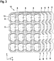
- FIG. 3 shows several frames 6, which are combined in the manner of an array or in a matrix arrangement in a plane A (ZY) and each hold an individually designed shaped body 5.
- This frame arrangement 12 has a honeycomb structure in plane A.
- adjacent frames 6 share a common frame wall section 13.
- a further frame arrangement level B is constructed, which, like the frame arrangement level A, consists of a plurality of frames arranged in a matrix arrangement with moldings arranged therein in honeycomb structure.
- the planes A and B are spaced apart from one another, which means that a molded body of plane A is not directly connected to the molded body of plane B lying behind it.
- the two levels A and B are only over with the Frame arrangement planes A and B integrally formed webs (not shown) are connected to one another, ie frames located one behind the other in the X direction are not directly connected to one another.
- These webs are designed in such a way that they are easy to break through, as a result of which the levels A / B can be easily separated from one another.
- levels C / D adjoin the level B and are designed analogously to the levels A / B.
Landscapes
- Engineering & Computer Science (AREA)
- Chemical & Material Sciences (AREA)
- Materials Engineering (AREA)
- Manufacturing & Machinery (AREA)
- Mechanical Engineering (AREA)
- Optics & Photonics (AREA)
- Physics & Mathematics (AREA)
- Ceramic Engineering (AREA)
- Inorganic Chemistry (AREA)
- Structural Engineering (AREA)
- Organic Chemistry (AREA)
- Producing Shaped Articles From Materials (AREA)
- Dental Prosthetics (AREA)
Abstract
Description
- Die vorliegende Erfindung betrifft ein Verfahren zum Herstellen von Formkörpern aus einem Baumaterial, insbesondere aus mit Keramik gefülltem Schlicker, mittels eines additiven Fertigungsverfahrens, bei dem während eines Bauvorgangs ein schichtweiser Aufbau eines Formkörpers durch aufeinanderfolgendes Verfestigen von Schichten des Baumaterials in einem Schichtgebiet mit einer für die jeweilige Schicht vorgegebenen Kontur durch Einwirkung elektromagnetischer Strahlung erfolgt.
- Der schichtweise oder kontinuierliche Aufbau von Formkörpern gehört zu den aufbauenden Verfahren, die unter den Oberbegriff generative Fertigung oder additive Fertigung (Additive Manufacturing) fallen. Darunter wird eine Klasse von Verfahrensweisen verstanden, bei denen ein dreidimensionales Objekt (Formkörper) direkt auf Grundlage eines digitalen Modells des Formkörpers (z.B. ein CAD-Modell) aufgebaut wird. Dazu wird beim schichtweisen Aufbau das digitale Modell des Formkörpers in eine Vielzahl von aufeinanderfolgenden dünnen Scheiben unterteilt, wobei jede Scheibe eine durch das Modell definierte Kontur hat. Der Aufbauprozess wird durch Hinzufügen von Materialschichten durchgeführt, wobei jede Schicht so prozessiert wird, dass die durch das digitale Modell für diese Schicht vorgegebene Kontur erzeugt wird. Schließlich bildet der Stapel von übereinanderliegenden, miteinander verbundenen Schichten den Formkörper, der bei einigen Verfahren weiter bearbeitet wird, zum Beispiel durch Wärmebehandlungen zum Entbindern und Sintern.
- Der Begriff "Kontur" wird im Zusammenhang mit der vorliegenden Erfindung allgemein gebraucht und ist nicht auf eine einfache geschlossene Begrenzungslinie eingeschränkt, die ein einfach zusammenhängendes Gebiet umschließt, sondern kann mehrere separate Konturabschnitte umfassen, die nebeneinander liegende Flächen umschließen, die zusammen die jeweilige Schicht bilden, oder es können äußere und innere Konturabschnitte vorhanden sein, die ringförmige Gebiete der Schicht definieren.
- Das Baumaterial, aus dem der Formkörper aufgebaut wird, wird durch elektromagnetische Strahlung ausgehärtet. Es kann neben photopolymerisierbaren Polymervorläuferverbindungen Füllstoffe wie Keramik-, Glas-Keramik- oder Metallpulver und gegebenenfalls Dispergiermittel und andere Additive enthalten. Die vorliegende Erfindung ist insbesondere auf die Herstellung von Keramik- oder Glaskeramikformteilen (sogenannten Grünlingen), wie dentalen Inlays, Onlays, Veneers, Kronen, Brücken und Gerüsten gerichtet.
- Aus der
WO 2010/045950 A1 , auf der der Oberbegriff von Anspruch 1 basiert, ist ein Beispiel für ein Verfahren zum Aufbau eines Formkörpers bekannt, das insbesondere den Aufbau von Dentalrestaurationen aus keramischen Schlickern betrifft, die eine flüssige photopolymerisierbare Komponente und darin verteilten Füllstoff aus keramischem oder Glas-keramischem Pulver enthalten. Bei diesem bekannten Verfahren wird der Formkörper sukzessive durch übereinander ausgehärtete Schichten aufgebaut. Dabei wird eine Bauplattform vertikal beweglich über einem Wannenboden gehalten, der zumindest im Baugebiet lichtdurchlässig ist. Unterhalb des Wannenbodens befindet sich eine Belichtungseinheit. Die Bauplattform wird zunächst in den Schlicker in der Wanne soweit abgesenkt, bis zwischen Bauplattform und Wannenboden nur noch eine Schicht mit der gewünschten Schichtdicke verbleibt. Anschließend wird diese Schicht durch die Belichtungseinheit mit der durch das digitale Modell für diese Schicht vorgegebenen Kontur durch die Belichtungseinheit belichtet und dadurch ausgehärtet. Nach Anheben der Bauplattform wird Schlicker, z.B. mit einer Rakel, aus der Umgebung nachgeführt und danach die Bauplattform erneut in den Schlicker abgesenkt, wobei die Absenkung so gesteuert wird, dass der Abstand zwischen der zuletzt ausgehärteten Schicht und dem Wannenboden eine Schicht Baumaterial mit der gewünschten Dicke definiert. Die letzten Schritte werden so oft wiederholt, bis durch die aufeinanderfolgende Aushärtung von Schichten mit jeweils durch das digitale Modell vorgegebener Kontur der Formkörper mit der gewünschten dreidimensionalen Form aufgebaut ist. - Nach vollständigem Aufbau des Formkörpers kann dieser mit der Bauplattform entnommen werden. In der Regel schließen sich daran noch weitere Bearbeitungsschritte an. In dem oben dargestellten Verfahren wird durch die schichtweise Polymerisation des Baumaterials ein Grünling hergestellt. Dieser wird dann auf hohe Temperaturen aufgeheizt, um das Bindemittel, in diesem Fall Photopolymer, zu entfernen. Dies geschieht bei hohen Temperaturen durch thermische Zersetzung und Reaktionen, die das Polymer in leichtere Moleküle zersetzen, die an die Oberfläche diffundieren und schließlich als Gase entweichen. An diesen Vorgang der Entbinderung kann sich dann zur weiteren Verfestigung eine weitere Temperaturbehandlung anschließen, in der die verbliebenen Keramikpartikel in dem Formkörper gesintert werden.
- Zur Sicherstellung der Stabilität im Bauprozess werden bei einigen Fertigungsverfahren Stützstrukturen aus dem Baumaterial mit aufgebaut, um den Formkörper während der Fertigung zu fixieren und auskragende Schichten und Überhänge gegen die Schwerkraft zu stützen. Stützstrukturen werden oftmals auch dazu verwendet, bei einigen additiven Fertigungsverfahren auftretende prozessbedingte Eigenspannungen abzustützen. Nachdem der Bauprozess abgeschlossen ist, müssen die Stützstrukturen zugänglich und möglichst leicht entfernbar sein.
- Prozessbedingte Eigenspannungen sind vor allem das Resultat thermischer Einflüsse auf den Formkörper. Eine Reihe von additiven Fertigungsverfahren ist mit starken Temperaturschwankungen verbunden. So sehen eine Reihe von Fertigungsverfahren Entbinderungs- und Sinterprozesse vor, in denen es infolge ungleichmäßiger Abkühlraten des Formkörpers zu Verzugserscheinungen kommen kann. Sinterverzug ist ein häufig beobachtetes Phänomen bei der Herstellung dichter Keramikbauteile. Dies ist gerade in Bereichen, die ein hohes Maß an Genauigkeit verlangen, nicht erwünscht. Als Beispiel ist hier die Dentaltechnik zu nennen. Eine Zahnkrone in Form des Grünkörpers kann im additiven Prozess beispielsweise dadurch hergestellt werden, indem photoreaktiver, mit Keramikpulver gefüllter Schlicker Schicht für Schicht ausgehärtet wird und das Bauteil die gewünschte dreidimensionale Form erhält. Im nächsten Schritt wird das Bauteil von Schlickerresten befreit und eventuelle Stützstrukturen, die zur Strukturierung notwendig waren, werden entfernt. In den Schritten der thermischen Nachbearbeitung werden zunächst beim Entbindern die Bindemittel herausgebrannt und anschließend die Keramik dicht gesintert. Hierbei kann es technisch bedingt zu Verzugserscheinungen des Formkörpers kommen. Ein möglichst geringer Verzug und eine hohe Passgenauigkeit sind aber für die Anbindung der Zahnkrone an den Zahnstumpf von wesentlicher Bedeutung.
- Die zuverlässige Fixierung des Formkörpers während des Bauvorgangs oder während der nachfolgenden Prozesse trägt folglich wesentlich zu der Genauigkeit und Qualität des gefertigten Formkörpers bei.
- Es ist daher Aufgabe der vorliegenden Erfindung, eine Verbesserung der Halterung des Formkörpers vorzuschlagen.
- Die der Erfindung zugrunde liegende Aufgabe wird durch ein Verfahren mit den Merkmalen des Anspruchs 1 gelöst. Vorteilhafte Ausgestaltungen der vorliegenden Erfindung sind Gegenstand der Unteransprüche.
- Erfindungsgemäß ist vorgesehen, dass beim Bauvorgang zusammen mit dem Formkörper schichtweise aus dem Baumaterial ein den Formkörper auf Abstand umlaufender hülsenartiger Rahmen aufgebaut wird. Dieser hülsenartige Rahmen, der nach Art einer Hülse eine umlaufende Seitenwand umfasst, erstreckt sich entlang eines Umfangs des Formkörpers, so dass der Formkörper innerhalb des hülsenartigen Rahmens angeordnet ist. Darüber hinaus werden beim Bauvorgang eine Vielzahl stiftartiger Verbindungen integral mit dem Rahmen und dem Formkörper aufgebaut. Diese stiftartigen Verbindungen oder Stege sind um den Formkörper herum verteilt und verbinden den Rahmen und den Formkörper auf unterschiedlichen Seiten des Formkörpers miteinander. Die Umfangsfläche des Formkörpers kann in mehrere Flächenabschnitte unterteilt sein, z.B. im Fall eines prismenförmigen Rahmens, und die stiftartigen Verbindungen können entlang des Umfangs des Formkörpers an unterschiedlichen Flächenabschnitten des Formkörpers mit diesem verbunden sein. Auch die innere Umfangsfläche des Rahmens kann in mehrere Innenwandabschnitte unterteilt sein, z.B. im Fall eines prismenförmigen Rahmens, und die stiftartigen Verbindungen können an unterschiedlichen Innenwandabschnitten des Rahmens ausgebildet sein.
- Der hülsenartige Rahmen hat vorzugsweise die Form eines an den Grundflächen offenen Zylinders. Unter Zylinder wird hier ein geometrischer Körper verstanden, bei dem zwei parallele, ebene, kongruente Grundflächen durch einen Mantel miteinander verbunden sind, wobei die Grundflächen selbst wie gesagt offen sind. Die Kontur der Grundflächen kann irgendeine geschlossene Kurve sein und ist nicht auf Kreisform beschränkt. Die Kontur der Grundflächen können auch geschlossene Polygone sein, wobei die resultierenden Körper in diesem Fall auch als Prismen bezeichnet werden. Die Längsachse solcher Rahmen ist die Zylinderachse.
- Zonen mit stiftartigen Verbindungen können gleichmäßig in einem Winkelabstand von beispielsweise 90° um eine Längsachse des Formkörpers vorgesehen sein. Die Längsachse des Formkörpers läuft in diesem Sinne in die gleiche Richtung wie die Längsachse des Rahmens. Die Längsachse des hülsenartigen Rahmens ist eine zentrale Achse, die der Rahmen umläuft. Möglich sind aber auch andere, vor allem auch ungleichmäßige Winkelabstände zwischen den stiftartigen Verbindungen. Die Anordnung der stiftartigen Verbindungen ist in erster Linie abhängig von der Form des Formkörpers, der an unterschiedlichen Flächen seines Körpers gestützt werden soll.
- Im Gegensatz zu einfachen Stützstrukturen bietet der integral ausgebildete Rahmen einen verbesserten Halt für den Formkörper während des Bauprozesses und nachfolgender Fertigungsprozesse. Anders als einfache Stützstrukturen, die den Formköper nur von unten abstützen, bietet der Rahmen die Möglichkeit, um den Umfang des Formkörpers herum eine Vielzahl von Befestigungsstellen zu errichten, die auf unterschiedlichen Seiten des Formköpers mit diesem verbunden sind. Die stiftartigen Verbindungen sind derart ausgebildet, dass der Formkörper durch Durchbrechen der stiftartigen Verbindungen aus dem Rahmen gelöst werden kann. Hierzu kann die Dicke der stiftartigen Verbindungen entsprechend dimensioniert werden.
- Vorzugsweise verlaufen die stiftartigen Verbindungen senkrecht zu der unmittelbaren Umgebung der entsprechenden Fläche des Formkörpers und/oder des Rahmens. Die stiftartigen Verbindungen können so ausgestaltet sein, dass sie den Abstand zwischen dem Rahmen und dem Formkörper auf kürzestmögliche Weise überbrücken. So werden Kräfte optimal in den Rahmen übertragen, der aufgrund seiner ringförmigen Geschlossenheit die Kräfte ohne wesentliche Verformung aufnimmt. Rahmen und stiftartige Verbindungen bilden somit ein optimales Versteifungsgerüst.
- Besondere Vorteile bietet die integrale Ausbildung des Formkörpers und des den Formkörper umlaufenden Rahmens auch in Bezug auf das Auftreten von Verzugserscheinungen in Form von Wärmebehandlungen, denn der den Formkörper umlaufende Rahmen schützt den Formkörper in effizienter Weise vor Verzug. Die an unterschiedlichen Positionen angreifenden stiftartigen Verbindungen bilden eine umfassende Stützstruktur und Haltestruktur für den Formkörper und verhindern damit Verzugserscheinungen in dem Formkörper in effizienter Weise.
- Die stiftartigen Verbindungen können einzeln oder in Gruppen um den Formkörper herum verteilt sein. Im Falle eines prismenförmigen Rahmens bedeutet eine Anordnung in Gruppen beispielsweise, dass mehrere stiftartige Verbindungen an einem gemeinsamen Flächenabschnitt des Formkörpers und/oder an einem gemeinsamen Innenwandabschnitt des Rahmens ausgebildet sind. Somit können Gruppen von stiftartigen Verbindungen entlang eines Umfangs des Formkörpers an unterschiedlichen Flächenabschnitten des Formkörpers mit diesem verbunden sein. Die Gruppenanordnung von stiftartigen Verbindungen bringt eine leicht lösbare, gleichzeitig aber besonders feste Halterung des Formkörpers in dem Rahmen mit sich.
- Gemäß einer weiteren Ausführungsform der Erfindung ist vorgesehen, dass die stiftartigen Verbindungen an der Innenseite des Rahmens aufgebaut werden. Dadurch ist der Materialverbrauch klein und die Außenbereiche des Rahmens können für weitere Formkörper genutzt werden.
- Der Rahmen kann eine Vielzahl von Formen im Querschnitt aufweisen. So ist beispielsweise mit Blick in Längsrichtung der Hülse im Querschnitt eine Kreisform möglich. Im Querschnitt sind aber auch andere Formen denkbar. So sehen weitere Ausführungsbeispiele der Erfindung im Querschnitt mehreckige Hülsen vor, beispielsweise sechseckige oder achteckige Querschnittsformen, die eine erhöhte Stabilität vorweisen.
- Nach einer weiteren Ausführungsform der Erfindung erfolgt die Verfestigung des Baumaterials innerhalb der vorgegebenen Kontur durch ortsselektive magnetische Bestrahlung, beispielsweise im Rahmen von stereolithographischer Photopolymerisation.
- Gemäß einer weiteren Ausführungsform der Erfindung ist das Baumaterial ein Keramikschlicker.
- Der Formkörper und der Rahmen können auf einer Bauplattform gefertigt werden, beispielsweise durch folgenden Prozess. Baumaterial wird zwischen der Bauplattform und einer transparenten Scheibe gefördert. Das Baumaterial wird durch die Scheibe hindurch ortselektiv belichtet, um oberhalb der Basisscheibe innerhalb einer vorgegebenen Kontur auszuhärten. Nachdem eine Schicht des Baukörpers, d.h. die integrale Einheit von Formkörper und Rahmen, verfestigt ist, wird sukzessiv die Bauplattform relativ zu der Basisscheibe angehoben. Anschließend wird Baumaterial nachgeführt und die vorhergehenden Schritte werden fortgesetzt, bis der Baukörper durch ortselektives Aushärten des Baumaterials aufgebaut ist.
- Gemäß einer weiteren Ausführungsform der Erfindung entspricht die Dimension des Formkörpers in Axialrichtung des hülsenartigen Rahmens im Wesentlichen der Dimension des Rahmens. Dadurch kann eine Abstützung des Formkörpers entlang seiner gesamten Länge erfolgen.
- Gemäß einer weiteren Ausführungsform der Erfindung wird neben den stiftartigen Verbindungen noch eine zusätzliche Stützstruktur, beispielsweise in Form einer Kreuzabstützung, die den Formkörper zusätzlich von unten stützt, aufgebaut.
- Gemäß einer weiteren Ausführungsform der Erfindung wird nach dem Bauvorgang des Rahmens und des Formkörpers eine Entbinderung und/oder Sinterung durchgeführt. Dies ist möglich bevor der Formkörper aus dem Rahmen gelöst wird, wobei der Rahmen den Formkörper während der Wärmebehandlung vor Verzugserscheinungen schützt. Alternativ sieht eine weitere Ausführungsform der Erfindung vor, dass nach dem Bauvorgang eine gemeinsame Entbinderung des Rahmens und des Formkörpers erfolgt. In einem weiteren Schritt wird der Formkörper aus dem Rahmen gelöst und anschließend gesintert. Dieser zweistufige Prozess, bei dem der Formkörper im Rahmen zunächst vorgesintert wird und die Endkristallisation nur an dem Formkörper selbst erfolgt, erleichtert die Entfernung der stiftartigen Verbindungen und einer eventuellen zusätzlichen Stützstruktur vom gesinterten Formkörper. Damit verbundener Werkzeugverschleiß wird dadurch reduziert.
- Der Abstand zwischen dem Rahmen und dem Formkörper ist derart gewählt, dass die Strukturen nicht zusammenwachsen, sondern nur durch die stiftartigen Verbindungen und eine eventuell zusätzliche Stützstruktur miteinander verbunden sind. Es hat sich dabei als vorteilhaft herausgestellt, wenn der Abstand zwischen dem Rahmen und dem Formkörper wenigstens 1,4 mm, bevorzugt wenigstens 1,5 mm, beträgt.
- Die Rahmenstärke, d.h. die Dicke der Rahmenwand, kann wenigstens 1,3 mm betragen, was zu einem geringen Materialverbrauch beiträgt, aber ausreichend Stützkräfte liefert.
- Eine weitere Ausführungsform der Erfindung sieht vor, dass der Formkörper aus dem Rahmen gelöst wird, indem die stiftartigen Verbindungen von dem Formkörper abgetrennt werden. Durch die stiftartigen Verbindungen ist es nicht notwendig, den Rahmen aufzuschneiden oder zu zerbrechen, was den gesamten Fertigungsprozess effizienter gestaltet. So kann der Formkörper durch ausschließliches Brechen der stiftartigen Verbindungen und Trennen einer eventuellen zusätzlichen Stützstruktur aus dem Rahmen gelöst werden.
- Eine weitere Ausführungsform der Erfindung sieht vor, dass beim Bauvorgang eine integrale Rahmenanordnung mit einer Vielzahl von Rahmen und darin angeordneten, insbesondere individuellen, Formenkörpern aufgebaut wird. Die Rahmenordnung kann die Form eines Arrays oder einer Matrix aufweisen, in der mehrere Rahmen in einer Ebene nebeneinander angeordnet sind und jeweils einen Formkörper halten. Da die Rahmen miteinander verbunden sind, stützen diese sich gegenseitig und tragen zu einer festen Struktur der einzelnen Halterungen für die einzelnen Formkörper bei. Durch das Vorsehen der integral ausgebildeten Rahmen kann eine Vielzahl von individuell gestalteten Formkörpern in einem Herstellungsprozess gleichzeitig hergestellt werden.
- Um die gleichzeitige Herstellung mehrerer Formkörper zu verbessern, sieht eine weitere Ausführungsform der Erfindung vor, dass die Rahmenanordnung eine Wabenstruktur aufweist, wobei sich benachbarte Rahmen vorzugsweise einen Rahmenwandabschnitt teilen. Die Wabenstruktur gilt allgemein als eine optimale Form mit einem idealen Verhältnis von Wandmaterial zu Volumen. Gleichzeitig stabilisiert diese Form die Gesamtkonstruktion.
- Eine weitere Ausführungsform der Erfindung sieht vor, dass die Rahmenanordnung mehrere übereinandergestapelte Rahmenanordungsebenen aufweist, innerhalb derer jeweils mehrere Rahmen und Formkörper, beispielsweise in Form einer Wabenstruktur, angeordnet sind. Das Aneinanderreihen und Stapeln der Rahmen erhöht die Produktionsmenge an hergestellten Formkörpern in signifikanter Weise. Kennzeichnend dabei ist, dass mehrere Rahmen und Formkörper in einer Ebene zusammengefasst werden, z.B. in einer Matrixanordnung mit Blickrichtung auf die Ebene. In einer parallel zu dieser ersten Ebene angeordneten zweiten Ebene werden weitere Rahmen und Formkörper aneinandergereiht, z.B. in Matrixanordnung, so dass die beiden Ebenen gestapelt, d.h. in Stapelbauweise, angeordnet sind.
- Gemäß einer weiteren Ausführungsform der Erfindung sind benachbarte Rahmenanordungsebenen, d.h. der Verbund von mehreren Rahmen und Formkörpern, voneinander beabstandet und durch integral ausgebildete Stege oder stiftartige Verbindungen miteinander verbunden. Durch Brechen dieser Stege sind die benachbarten Rahmenanordungsebenen dadurch in einfacher Art und Weise voneinander trennbar.
- Grundsätzlich ist es möglich, dass zusammen mit dem Rahmen beim Bauvorgang an dem Rahmen Informationsträgerelemente, wie Nummern, QR-Codes oder sonstige Markierungen aufgebaut werden, die der Identifikation der individuellen Formkörper dienen.
- Nach einer weiteren Ausführungsform der Erfindung wird beim Bauvorgang eine zusätzliche Stützstruktur integral mit dem Rahmen und dem Formkörper aufgebaut, die den Formkörper während des Bauvorgangs zusätzlich sichert und während des Bauvorgangs auf den Formkörper wirkende Kräfte aufnimmt. Wenn, wie in der
WO 2010/045950 A1 beschrieben, der sich im Bauprozess befindliche Formkörper entlang einer Verfahrachse wiederkehrend in den Schlicker abgesenkt und aus diesem angehoben wird, können Kräfte zwischen dem Formkörper, dem Rahmen und dem Wannenboden wirken und die Struktur des gesamten Bauobjektes beeinträchtigen. Insbesondere treten nach dem Aushärten einer Schicht, wenn diese beim Anheben der Bauplattform vom Wannenboden abgelöst wird, unter Umständen, z.B. wenn ausgedehnte ausgehärtete Gebiete am Wannenboden haften, erhebliche Zugkräfte auf, die von der Bauplattform über den Rahmen auf den im Aufbau befindlichen Formkörper übertragen werden müssen. Diese Zugkräfte können effektiv durch die Stützstruktur aufgenommen werden. Vorzugsweise ist die Stützstruktur entlang der Verfahrachse der Bauplattform zwischen der der Bauplattform gegenüberliegenden Seite des Rahmens und dem Formkörper angeordnet, um die Zugkräfte, die entlang der Verfahrachse auf den Formkörper wirken, aufzunehmen. - Das erfindungsgemäße Verfahren hat sich besonders vorteilhaft im Bereich der Dentaltechnik erwiesen. Gemäß einer weiteren Ausführungsform der Erfindung ist daher vorgesehen, dass der Formkörper ein Zahnersatzteil, wie z.B. eine Zahnkrone, ein Inlay, ein Onlay, ein Veneer, eine Brücke oder ein Gerüst ist.
- Gerade bei Dentalprodukten ist die Genauigkeit der Flächen von besonderer Bedeutung. Bei Zahnersatzteilen, wie beispielsweise bei Kronen, sind die occlusalen Oberflächen, aber auch die innere Oberfläche, die der Anbindung an den Zahnstumpf dient, von besonderer Bedeutung. Es empfiehlt sich daher, die Verbindungen zwischen dem Formkörper und dem Rahmen an anderer Stelle vorzunehmen. Besonders geeignete Stellen sind hierbei die oralen oder vestibulären Flächen des Zahnersatzteils, wobei die oralen Flächen des Zahnersatzteils besonders bevorzugt sind. Diese Flächen der Zahnersatzteile sind ideal für die Anbringung der Stützstruktur geeignet. Insgesamt trägt dies zu einer hohen Genauigkeit der relevanten Flächen, insbesondere der occlusalen oder der inneren Oberfläche des Zahnersatzteils bei.
- Die vorliegende Erfindung wird im Folgenden anhand lediglich bevorzugter Ausführungsbeispiele und den Zeichnungen näher erläutert:
Es zeigen: - Figur 1a,b
- in einer Seitenansicht die digitale Vorlage einer Zahnkrone auf einer Stützstruktur sowie in einer schrägen Draufsicht die gefertigte Zahnkrone nach dem Sintern,
- Figur 2a,b
- einen nach einer erste Ausführungsform der Erfindung hergestellten Rahmen mit einem darin angeordneten Formkörper, und
- Figur 3
- eine nach einer weiteren Ausführungsform der Erfindung hergestellte Rahmenanordnung.
-
Figur 1a zeigt die digitale Vorlage eines Formkörpers 1 in Form einer Zahnkrone auf einer Stützstruktur 2. Anschließend wird diese digitale Vorlage genutzt, um mittels eines additiven Fertigungsverfahrens, bei dem mit Keramik gefüllter Schlicker ortselektiv gehärtet wird, den Formkörper 1 und die Stützstruktur 2 schichtweise aufzubauen. Die Zahnkrone 1 wird durch die Stützstruktur 2 an den Höckern der occlusalen Fläche der Zahnkrone gestützt. Während des Herstellungsprozesses, bei dem eine Sinterung stattfindet, bewirkt die Stützstruktur 2 eine Versteifung der Krone 1. Die Stützstruktur 2 wird nach der Herstellung der Krone entfernt. -
Figur 1b zeigt die Zahnkrone 1 nach der Fertigung. Eingerahmt sind hier die Bereiche 3 und 4, die von der Anordnung der Stützstruktur 2 abgewandt sind. In diesen Bereichen kommt es zu vergleichsweise großen Verzugserscheinungen während des Sinterprozesses. -
Figuren 2a und 2b zeigen einen Formkörper und einen Rahmen, die integral nach einer ersten Ausführungsform der Erfindung hergestellt sind. Beim Bauvorgang wurde zusammen, d.h. integral mit dem Formkörper 5 (Zahnkrone) schichtweise aus dem Baumaterial der den Formkörper 5 auf Abstand umlaufende hülsenartige Rahmen 6 aufgebaut. Der hülsenartige Rahmen 6 erstreckt sich in Axialrichtung 7 bzw. entlang seiner Längsachse 8. Die Seitenwand 9 des Rahmens 6 verläuft um die Achsen 7 und 8. Die Darstellung in derFigur 2a ist eine Draufsicht auf die Kaufläche der Zahnkrone entlang der Achsen 7 und 8. DieFigur 2b stellt den Rahmen 6 und die darin angeordnete Krone 5 in einer Seitenansicht dar. - Im Querschnitt, d.h. in Richtung der Längsachse 8 gesehen, weist der Rahmen eine mehreckige Form auf, hier in Form eines Achtecks. Diese Form verleiht dem Rahmen 6 zusätzliche Stabilität. Die Seitenwand 9 erstreckt sich um den Umfang des Formkörpers 5 um die Achse 7. An der Innenwand der Seitenwand 9 des Rahmens 6 wurden beim Bauvorgang integral mit dem Rahmen und dem Formkörper ausgebildete stiftartige Verbindungen 10 aufgebaut. Diese sind in Axialrichtung 7 gesehen um den Formkörperumfang herum verteilt und verbinden den Formkörper mit dem Rahmen. Die Verbindungen 10 dienen insbesondere als Verzugsvermeidungsstrukturen und verhindern einen Verzug des Formkörpers bei Wärmebehandlungsmaßnahmen.
- Zusätzlich zu den Verbindungen 10 ist noch eine Stützstruktur 11 unterhalb des Formkörpers 5 integral mit dem Formkörper und dem Rahmen 6 aufgebaut. Das Bauobjekt, d.h. die Gesamtheit aus Rahmen 6, Formkörper 5, Verbindungen 10 und Stützstruktur 11, ist während des Bauvorgangs auf einer nicht dargestellten Bauplattform aufgebaut worden, die in
Figur 2a an der Außenseite der unteren Rahmenwand, an deren Innenseite sich der Stützkörper 11 befindet, liegt. Ein entsprechendes Verfahren, bei dem das sich im Bau befindliche Bauobjekt an der Bauplattform wiederholend in den Schlicker eingetaucht und wieder angehoben und so von der Bauplattform ausgehend schichtweise aufgebaut wird, wurde einleitend in Bezug auf dieWO 2010/045950 A1 beschrieben. Die während des Bauprozesses auf den Formkörper 5 wirkenden Zugkräfte verlaufen durch die Stützstruktur 11 und werden durch diese effektiv aufgenommen und über den Rahmen auf die Bauplattform übertragen. - In Axialrichtung 7 entspricht die Dimension des Formkörpers 5, d.h. die Länge, über die sich der Formkörper 5 in Axialrichtung 7 erstreckt, im Wesentlichen der Dimension des Rahmens 6 in Axialrichtung 7. Die stiftartigen Verbindungen sind in Gruppen zu je drei stiftartigen Verbindungen über den Umfang des Formkörpers 5 verteilt, hier im Wesentlichen in einem Abstand von ca. 90°. Andere Winkelabstände (z.B. 45°, 60°, 120°) sind ebenfalls möglich. Entscheidend ist jedoch, dass die stiftartigen Verbindungen an unterschiedlichen Abschnitten des Umfangs des Formkörpers angreifen, um eine effiziente Fixierung des Formkörpers 5 im Fertigungsprozess zu gewährleisten. Die Dicke der stiftartigen Verbindungen 10 ist so gewählt, dass diese einfach zu durchbrechen sind, wodurch der Formkörper 5 in einfacher Art und Weise aus dem Rahmen 6 herausgelöst werden kann.
-
Figur 3 zeigt mehrere Rahmen 6, die nach Art eines Arrays oder in einer Matrix-Anordnung in einer Ebene A (Z-Y) zusammengefasst sind und jeweils einen individuell gestalteten Formkörper 5 halten. Diese Rahmenanordnung 12 weist in der Ebene A eine Wabenstruktur auf. Innerhalb dieser Wabenstruktur der Ebene A teilen sich benachbarte Rahmen 6 einen gemeinsamen Rahmenwandabschnitt 13. In X-Richtung hinter der ersten Rahmenanordnungsebene A ist eine weitere Rahmenanordnungsebene B aufgebaut, die ebenso wie die Rahmenanordnungsebene A aus einer Vielzahl von in Matrixanordnung angeordneten Rahmen mit darin angeordneten Formkörpern in Wabenstruktur besteht. Die Ebenen A und B sind voneinander beabstandet, was bedeutet, dass ein Formkörper der Ebene A nicht unmittelbar mit dem dahinterliegenden Formkörper der Ebene B verbunden ist. Tatsächlich sind die beiden Ebenen A und B lediglich über mit den Rahmenanordnungsebenen A und B integral ausgebildete Stege (nicht dargestellt) miteinander verbunden, d.h. in X-Richtung hintereinander liegende Rahmen sind nicht direkt miteinander verbunden. Diese Stege sind derart ausgebildet, dass sie leicht zu durchbrechen sind, wodurch die Ebenen A/B leicht voneinander getrennt werden können. - An die Ebene B schließen weitere Ebenen C/D an, die analog zu den Ebenen A/B ausgebildet sind.
-
- 1
- Zahnkrone
- 2
- Stützstruktur
- 3
- Bereich mit besonderer Verzugsneigung
- 4
- Bereich mit besonderer Verzugsneigung
- 5
- Formkörper
- 6
- Rahmen
- 7
- Axialrichtung
- 8
- Längsachse
- 9
- Seitenwand des Rahmens
- 10
- Verbindungen
- 11
- Stützstruktur
- 12
- Rahmenanordnung
- 13
- gemeinsamer Rahmenwandabschnitt
- A
- 1. Rahmenanordnungsebene
- B
- 2. Rahmenanordnungsebene
- C
- 3. Rahmenanordnungsebene
- D
- 4. Rahmenanordnungsebene
Claims (15)
- Verfahren zum Herstellen von Formkörpern (5) aus einem Baumaterial, insbesondere aus mit Keramik gefülltem Schlicker, mittels eines additiven Fertigungsverfahrens, bei dem während eines Bauvorgangs ein schichtweiser Aufbau eines Formkörpers (5) durch aufeinanderfolgendes Verfestigen von Schichten des Baumaterials in einem Schichtgebiet mit einer für die jeweilige Schicht vorgegebenen Kontur durch Einwirkung elektromagnetischer Strahlung erfolgt,
dadurch gekennzeichnet,
dass beim Bauvorgang zusammen mit dem Formkörper (5) schichtweise aus dem Baumaterial ein den Formkörper auf Abstand umlaufender hülsenartiger Rahmen (6) aufgebaut wird, und dass beim Bauvorgang darüber hinaus eine Vielzahl stiftartiger Verbindungen (10) integral mit dem Rahmen (6) und dem Formkörper (5) aufgebaut werden, die um den Formkörper (5) herum verteilt sind und die den Formkörper (5) mit dem Rahmen (6) verbinden. - Verfahren nach Anspruch 1, dadurch gekennzeichnet, dass die stiftartigen Verbindungen (10) an der Innenseite des Rahmens (6) aufgebaut werden.
- Verfahren nach Anspruch 1 oder 2, dadurch gekennzeichnet, dass die Verfestigung des Baumaterials innerhalb der vorgegebenen Kontur durch ortsselektive elektromagnetische Bestrahlung erfolgt.
- Verfahren nach einem der vorhergehenden Ansprüche, dadurch gekennzeichnet, dass das Baumaterial ein Keramikschlicker ist.
- Verfahren nach einem der vorhergehenden Ansprüche, dadurch gekennzeichnet, dass in Axialrichtung (7) des hülsenartigen Rahmens (6) die Dimension des Formkörpers (5) im Wesentlichen der Dimension des Rahmens (6) entspricht.
- Verfahren nach einem der vorhergehenden Ansprüche, dadurch gekennzeichnet, dass nach dem Bauvorgang eine Entbinderung und/oder Sinterung durchgeführt wird.
- Verfahren nach einem der Ansprüche 1-5, dadurch gekennzeichnet, dass nach dem Bauvorgang eine Entbinderung des Rahmens (10) und des Formkörpers (5) erfolgt und dass in einem weiteren Schritt der Formkörper (5) aus dem Rahmen (6) gelöst und anschließend gesintert wird.
- Verfahren nach einem der vorhergehenden Ansprüche, dadurch gekennzeichnet, dass der Formkörper (5) aus dem Rahmen (6) gelöst wird, indem die stiftartigen Verbindungen (10) von dem Formkörper (5) abgetrennt werden.
- Verfahren nach einem der vorhergehenden Ansprüche, dadurch gekennzeichnet, dass beim Bauvorgang eine integrale Rahmenanordnung (12) mit einer Vielzahl von Rahmen (6) und darin angeordneten Formkörpern (5) aufgebaut wird.
- Verfahren nach Anspruch 9, dadurch gekennzeichnet, dass die Rahmenanordnung (12) eine Wabenstruktur aufweist, wobei sich benachbarte Rahmen (6) einen Rahmenwandabschnitt (13) teilen.
- Verfahren nach einem der Ansprüche 9 und 10, dadurch gekennzeichnet, dass die Rahmenanordnung (12) mehrere übereinander gestapelte Rahmenanordnungsebenen (A, B, C, D), innerhalb derer jeweils mehrere Rahmen (6) und Formkörper (5) angeordnet sind, umfasst.
- Verfahren nach Anspruch 11, dadurch gekennzeichnet, dass benachbarte Rahmenanordnungsebenen (A, B, C, D) voneinander beabstandet und durch integral ausgebildete Stege miteinander verbunden sind, so dass benachbarte Rahmenanordnungsebenen (A, B, C, D) durch Brechen der Stege voneinander trennbar sind.
- Verfahren nach einem der vorhergehenden Ansprüche, dadurch gekennzeichnet, dass der Formkörper (5) ein Zahnersatzteil, wie eine Zahnkrone, ist.
- Verfahren nach Anspruch 13, dadurch gekennzeichnet, dass die stiftartigen Verbindungen (10), die das Zahnersatzteil (5) mit dem Rahmen (6) verbinden, an den oralen oder vestibulären Flächen des Zahnersatzteils (5) aufgebaut werden.
- Verfahren nach einem der vorhergehenden Ansprüche, dadurch gekennzeichnet, dass der schichtweise Aufbau des Formkörpers auf einer Bauplattform erfolgt, und dass integral mit dem Rahmen (6) und dem Formkörper (5) eine zusätzliche Stützstruktur (11) zwischen der der Bauplattform gegenüberliegenden Seite des Rahmens (6) und dem Formkörper (5) aufgebaut wird, um während des Bauvorgangs auf den Formkörper (5) wirkende Kräfte aufzunehmen.
Priority Applications (6)
| Application Number | Priority Date | Filing Date | Title |
|---|---|---|---|
| EP18209713.9A EP3663074B1 (de) | 2018-12-03 | 2018-12-03 | Verfahren zur additiven fertigung von formkörpern |
| ES18209713T ES2942271T3 (es) | 2018-12-03 | 2018-12-03 | Procedimiento para la fabricación aditiva de cuerpos moldeados |
| US16/679,584 US11858169B2 (en) | 2018-12-03 | 2019-11-11 | Method for the additive manufacture of shaped bodies |
| CN201911189172.7A CN111331848B (zh) | 2018-12-03 | 2019-11-27 | 成型体的增材制造方法 |
| KR1020190154761A KR102528121B1 (ko) | 2018-12-03 | 2019-11-27 | 성형체의 적층 제조를 위한 방법 |
| JP2019217988A JP7345375B2 (ja) | 2018-12-03 | 2019-12-02 | 成形体の付加製造のための方法 |
Applications Claiming Priority (1)
| Application Number | Priority Date | Filing Date | Title |
|---|---|---|---|
| EP18209713.9A EP3663074B1 (de) | 2018-12-03 | 2018-12-03 | Verfahren zur additiven fertigung von formkörpern |
Publications (2)
| Publication Number | Publication Date |
|---|---|
| EP3663074A1 true EP3663074A1 (de) | 2020-06-10 |
| EP3663074B1 EP3663074B1 (de) | 2023-03-15 |
Family
ID=64572147
Family Applications (1)
| Application Number | Title | Priority Date | Filing Date |
|---|---|---|---|
| EP18209713.9A Active EP3663074B1 (de) | 2018-12-03 | 2018-12-03 | Verfahren zur additiven fertigung von formkörpern |
Country Status (6)
| Country | Link |
|---|---|
| US (1) | US11858169B2 (de) |
| EP (1) | EP3663074B1 (de) |
| JP (1) | JP7345375B2 (de) |
| KR (1) | KR102528121B1 (de) |
| CN (1) | CN111331848B (de) |
| ES (1) | ES2942271T3 (de) |
Families Citing this family (6)
| Publication number | Priority date | Publication date | Assignee | Title |
|---|---|---|---|---|
| US11679547B2 (en) * | 2019-03-27 | 2023-06-20 | 3D Systems, Inc. | High productivity system for printing precision articles |
| CN112685945B (zh) * | 2021-01-11 | 2021-08-13 | 北京理工大学 | 一种面向增材制造的磁-结构多物理场拓扑优化设计方法 |
| CN113199750B (zh) * | 2021-06-21 | 2022-01-07 | 安庆瑞迈特科技有限公司 | 一种准直器的高效3d打印方法 |
| DE102021118411A1 (de) * | 2021-07-16 | 2023-01-19 | Bionic Production GmbH | Herstellungsverfahren und Verzugskompensator zur additiven Bauteilfertigung |
| CN114433873B (zh) * | 2022-02-25 | 2023-06-06 | 鑫精合激光科技发展(北京)有限公司 | 一种增材制造方法 |
| CN119548293B (zh) * | 2024-11-28 | 2025-10-31 | 大博医疗科技股份有限公司 | 一种椎间融合器的激光打印方法 |
Citations (6)
| Publication number | Priority date | Publication date | Assignee | Title |
|---|---|---|---|---|
| US5135379A (en) * | 1988-11-29 | 1992-08-04 | Fudim Efrem V | Apparatus for production of three-dimensional objects by photosolidification |
| US5216616A (en) * | 1989-06-26 | 1993-06-01 | Masters William E | System and method for computer automated manufacture with reduced object shape distortion |
| US5386500A (en) * | 1987-06-02 | 1995-01-31 | Cubital Ltd. | Three dimensional modeling apparatus |
| WO2010045950A1 (de) | 2008-10-20 | 2010-04-29 | Ivoclar Vivadent Ag | Vorrichtung und verfahren zur verarbeitung von lichtpolymerisierbarem material zum schichtweisen aufbau von formkörpern |
| EP3205421A1 (de) * | 2016-02-11 | 2017-08-16 | General Electric Company | Verfahren und umgebende träger zur generativen fertigung |
| US20180036205A1 (en) * | 2016-08-03 | 2018-02-08 | Xerox Corporation | System and method for printing edible medicament dosage containers having identifying indicia at dispensing sites |
Family Cites Families (13)
| Publication number | Priority date | Publication date | Assignee | Title |
|---|---|---|---|---|
| JPH0742482B2 (ja) * | 1990-08-10 | 1995-05-10 | 日本電信電話株式会社 | 光成形法 |
| US6936212B1 (en) * | 2002-02-07 | 2005-08-30 | 3D Systems, Inc. | Selective deposition modeling build style providing enhanced dimensional accuracy |
| DE10223796C1 (de) * | 2002-05-29 | 2003-07-10 | Univ Clausthal Tech | Aus Elementen zusammengesetzte Struktur und Verfahren zu seiner Herstellung |
| EP2431006A1 (de) | 2010-09-16 | 2012-03-21 | 3M Innovative Properties Company | Verfahren zur Herstellung eines Zahnersatzes |
| US20170128174A1 (en) | 2014-06-23 | 2017-05-11 | 3M Innovative Properties Company | Process for producing a sintered lithium disilicate glass ceramic dental restoration and kit of parts |
| DE102014113148A1 (de) * | 2014-09-12 | 2016-03-31 | Amann Girrbach Ag | Sinterrohling |
| US20170021570A1 (en) * | 2015-03-24 | 2017-01-26 | Technology Research Association For Future Additive Manufacturing | Three-dimensional fabricating system, method of manufacturing three-dimensional fabricated object, information processing apparatus, method of generating structure for heat dissipation of three-dimensional fabricated object, and program for generating structure for heat dissipation of three-dimensional fabricated object |
| CN106273438B (zh) * | 2015-05-11 | 2019-11-05 | 三纬国际立体列印科技股份有限公司 | 立体打印成型结构 |
| DE102015217469A1 (de) * | 2015-09-11 | 2017-03-16 | Eos Gmbh Electro Optical Systems | Verfahren und Vorrichtung zum Herstellen eines dreidimensionalen Objekts |
| JP2017077683A (ja) * | 2015-10-21 | 2017-04-27 | ローランドディー.ジー.株式会社 | 3次元造形システムおよび3次元造形物の製造方法 |
| DE102016124401A1 (de) * | 2016-12-14 | 2018-06-14 | Cl Schutzrechtsverwaltungs Gmbh | Verfahren zur additiven Herstellung eines dreidimensionalen Objekts |
| JP6871003B2 (ja) | 2017-02-03 | 2021-05-12 | 日本特殊陶業株式会社 | セラミック成形体の製造方法 |
| WO2019210285A2 (en) * | 2018-04-26 | 2019-10-31 | San Diego State University | Selective sintering-based fabrication of fully dense complex shaped parts |
-
2018
- 2018-12-03 ES ES18209713T patent/ES2942271T3/es active Active
- 2018-12-03 EP EP18209713.9A patent/EP3663074B1/de active Active
-
2019
- 2019-11-11 US US16/679,584 patent/US11858169B2/en active Active
- 2019-11-27 CN CN201911189172.7A patent/CN111331848B/zh active Active
- 2019-11-27 KR KR1020190154761A patent/KR102528121B1/ko active Active
- 2019-12-02 JP JP2019217988A patent/JP7345375B2/ja active Active
Patent Citations (6)
| Publication number | Priority date | Publication date | Assignee | Title |
|---|---|---|---|---|
| US5386500A (en) * | 1987-06-02 | 1995-01-31 | Cubital Ltd. | Three dimensional modeling apparatus |
| US5135379A (en) * | 1988-11-29 | 1992-08-04 | Fudim Efrem V | Apparatus for production of three-dimensional objects by photosolidification |
| US5216616A (en) * | 1989-06-26 | 1993-06-01 | Masters William E | System and method for computer automated manufacture with reduced object shape distortion |
| WO2010045950A1 (de) | 2008-10-20 | 2010-04-29 | Ivoclar Vivadent Ag | Vorrichtung und verfahren zur verarbeitung von lichtpolymerisierbarem material zum schichtweisen aufbau von formkörpern |
| EP3205421A1 (de) * | 2016-02-11 | 2017-08-16 | General Electric Company | Verfahren und umgebende träger zur generativen fertigung |
| US20180036205A1 (en) * | 2016-08-03 | 2018-02-08 | Xerox Corporation | System and method for printing edible medicament dosage containers having identifying indicia at dispensing sites |
Also Published As
| Publication number | Publication date |
|---|---|
| ES2942271T3 (es) | 2023-05-31 |
| CN111331848A (zh) | 2020-06-26 |
| CN111331848B (zh) | 2022-05-17 |
| KR102528121B1 (ko) | 2023-05-02 |
| JP2020090098A (ja) | 2020-06-11 |
| US11858169B2 (en) | 2024-01-02 |
| JP7345375B2 (ja) | 2023-09-15 |
| EP3663074B1 (de) | 2023-03-15 |
| US20200171701A1 (en) | 2020-06-04 |
| KR20200067755A (ko) | 2020-06-12 |
Similar Documents
| Publication | Publication Date | Title |
|---|---|---|
| EP3663074B1 (de) | Verfahren zur additiven fertigung von formkörpern | |
| EP2470113B1 (de) | Verfahren zur herstellung von zahnteilen aus dentalmetallpulver | |
| EP0597237B1 (de) | Verfahren zum stirnseitigen, wechselweisen Verschliessen von Kanälen eines Wabenkörper-Monolithen für Abgasreinigungsanlagen von Verbrennungsmotoren | |
| DE102007048385B3 (de) | Verfahren zur Herstellung eines Bauteils, das im Wege eines generativen Ferti- gungsprozesses hergestellt wird | |
| EP3083870B1 (de) | Verfahren zur herstellung von mehrschicht-schleifpartikeln | |
| EP2779937B1 (de) | Rohling für künstliche zähne mit mehreren unterschiedlichen farbschichten und verfahren zu dessen herstellung | |
| DE10042134C2 (de) | Verfahren zur Herstellung von dreidimensionalen Sinter-Werkstücken | |
| WO2003039844A1 (de) | Verfahren zur herstellung von dreidimensionalen sinter-werkstücken | |
| EP3253514B1 (de) | Verfahren und vorrichtung zur additiven herstellung von bauteilen, und durch dieses verfahren hergestellte bauteile | |
| EP1087720A1 (de) | Verfahren zur herstellung medizinischer, zahnmedizinischer, zahntechnischer und technischer teile aus keramik | |
| DE102009057540B4 (de) | Verfahren zur Herstellung dreidimensional geformter Artikel | |
| DE102017101834A1 (de) | Automatisiertes Abtrennen von Stützstrukturen von einem Pulverbett-basiert additiv hergestellten Bauteil | |
| EP3930625B1 (de) | Verfahren zum herstellen eines formkörpers und geschichteter formkörper | |
| EP3003208B1 (de) | Prothesenvorkörper zur herstellung eines dentalen prothesenkörpers | |
| EP2034947B1 (de) | Material und rohling für zahnersatz | |
| EP1663052B1 (de) | Rohling und zwischenkörper zur herstellung eines zahnersatzteils | |
| WO2019137963A1 (de) | VERFAHREN ZUM METALLPULVERSPRITZGIEßEN | |
| EP1601304A1 (de) | Verfahren zur herstellung eines zahnersatzteils aus metallischen werkstoffen und rohling hierzu | |
| DE102005045698B4 (de) | Formkörper aus einer Dentallegierung zur Herstellung von dentalen Teilen | |
| EP1484031B1 (de) | Verfahren und Vorrichtung zur Herstellung einer dentalkeramischen Struktur | |
| DE10022870C2 (de) | Werkzeugform und Verfahren zur Generierung von Werkzeugformen | |
| DE102016203055B4 (de) | Verfahren und System zum Erzeugen einer Dentalrestauration | |
| WO2016113107A1 (de) | Bauweise mit gestapelten bauplatten und vorgehensweise bei einer am-anlage | |
| DE3841903A1 (de) | Verfahren zur herstellung einer dekoration aus edelmetall | |
| EP3064169B1 (de) | Verfahren zur herstellung einer dentalkeramik sowie dentalkeramik-erzeugungsvorrichtung |
Legal Events
| Date | Code | Title | Description |
|---|---|---|---|
| PUAI | Public reference made under article 153(3) epc to a published international application that has entered the european phase |
Free format text: ORIGINAL CODE: 0009012 |
|
| STAA | Information on the status of an ep patent application or granted ep patent |
Free format text: STATUS: THE APPLICATION HAS BEEN PUBLISHED |
|
| AK | Designated contracting states |
Kind code of ref document: A1 Designated state(s): AL AT BE BG CH CY CZ DE DK EE ES FI FR GB GR HR HU IE IS IT LI LT LU LV MC MK MT NL NO PL PT RO RS SE SI SK SM TR |
|
| AX | Request for extension of the european patent |
Extension state: BA ME |
|
| STAA | Information on the status of an ep patent application or granted ep patent |
Free format text: STATUS: REQUEST FOR EXAMINATION WAS MADE |
|
| 17P | Request for examination filed |
Effective date: 20201126 |
|
| RBV | Designated contracting states (corrected) |
Designated state(s): AL AT BE BG CH CY CZ DE DK EE ES FI FR GB GR HR HU IE IS IT LI LT LU LV MC MK MT NL NO PL PT RO RS SE SI SK SM TR |
|
| STAA | Information on the status of an ep patent application or granted ep patent |
Free format text: STATUS: EXAMINATION IS IN PROGRESS |
|
| 17Q | First examination report despatched |
Effective date: 20220728 |
|
| REG | Reference to a national code |
Ref country code: DE Ref legal event code: R079 Ref document number: 502018011761 Country of ref document: DE Free format text: PREVIOUS MAIN CLASS: B29C0064124000 Ipc: B29C0064400000 |
|
| GRAP | Despatch of communication of intention to grant a patent |
Free format text: ORIGINAL CODE: EPIDOSNIGR1 |
|
| STAA | Information on the status of an ep patent application or granted ep patent |
Free format text: STATUS: GRANT OF PATENT IS INTENDED |
|
| RIC1 | Information provided on ipc code assigned before grant |
Ipc: B28B 1/00 20060101ALI20221130BHEP Ipc: B33Y 80/00 20150101ALI20221130BHEP Ipc: B33Y 10/00 20150101ALI20221130BHEP Ipc: B29C 64/135 20170101ALI20221130BHEP Ipc: B29C 64/182 20170101ALI20221130BHEP Ipc: B29C 64/124 20170101ALI20221130BHEP Ipc: B29C 64/40 20170101AFI20221130BHEP |
|
| INTG | Intention to grant announced |
Effective date: 20221216 |
|
| RIN1 | Information on inventor provided before grant (corrected) |
Inventor name: GMEINER, ROBERT Inventor name: SCHOENHERR, JULIA ANNA Inventor name: EBERT, JOERG |
|
| GRAS | Grant fee paid |
Free format text: ORIGINAL CODE: EPIDOSNIGR3 |
|
| GRAA | (expected) grant |
Free format text: ORIGINAL CODE: 0009210 |
|
| STAA | Information on the status of an ep patent application or granted ep patent |
Free format text: STATUS: THE PATENT HAS BEEN GRANTED |
|
| AK | Designated contracting states |
Kind code of ref document: B1 Designated state(s): AL AT BE BG CH CY CZ DE DK EE ES FI FR GB GR HR HU IE IS IT LI LT LU LV MC MK MT NL NO PL PT RO RS SE SI SK SM TR |
|
| REG | Reference to a national code |
Ref country code: CH Ref legal event code: EP Ref country code: GB Ref legal event code: FG4D Free format text: NOT ENGLISH |
|
| REG | Reference to a national code |
Ref country code: DE Ref legal event code: R096 Ref document number: 502018011761 Country of ref document: DE |
|
| REG | Reference to a national code |
Ref country code: IE Ref legal event code: FG4D Free format text: LANGUAGE OF EP DOCUMENT: GERMAN |
|
| REG | Reference to a national code |
Ref country code: AT Ref legal event code: REF Ref document number: 1553743 Country of ref document: AT Kind code of ref document: T Effective date: 20230415 |
|
| REG | Reference to a national code |
Ref country code: NL Ref legal event code: FP |
|
| REG | Reference to a national code |
Ref country code: SE Ref legal event code: TRGR |
|
| REG | Reference to a national code |
Ref country code: ES Ref legal event code: FG2A Ref document number: 2942271 Country of ref document: ES Kind code of ref document: T3 Effective date: 20230531 |
|
| REG | Reference to a national code |
Ref country code: LT Ref legal event code: MG9D |
|
| P01 | Opt-out of the competence of the unified patent court (upc) registered |
Effective date: 20230607 |
|
| PG25 | Lapsed in a contracting state [announced via postgrant information from national office to epo] |
Ref country code: RS Free format text: LAPSE BECAUSE OF FAILURE TO SUBMIT A TRANSLATION OF THE DESCRIPTION OR TO PAY THE FEE WITHIN THE PRESCRIBED TIME-LIMIT Effective date: 20230315 Ref country code: NO Free format text: LAPSE BECAUSE OF FAILURE TO SUBMIT A TRANSLATION OF THE DESCRIPTION OR TO PAY THE FEE WITHIN THE PRESCRIBED TIME-LIMIT Effective date: 20230615 Ref country code: LV Free format text: LAPSE BECAUSE OF FAILURE TO SUBMIT A TRANSLATION OF THE DESCRIPTION OR TO PAY THE FEE WITHIN THE PRESCRIBED TIME-LIMIT Effective date: 20230315 Ref country code: LT Free format text: LAPSE BECAUSE OF FAILURE TO SUBMIT A TRANSLATION OF THE DESCRIPTION OR TO PAY THE FEE WITHIN THE PRESCRIBED TIME-LIMIT Effective date: 20230315 Ref country code: HR Free format text: LAPSE BECAUSE OF FAILURE TO SUBMIT A TRANSLATION OF THE DESCRIPTION OR TO PAY THE FEE WITHIN THE PRESCRIBED TIME-LIMIT Effective date: 20230315 |
|
| PG25 | Lapsed in a contracting state [announced via postgrant information from national office to epo] |
Ref country code: GR Free format text: LAPSE BECAUSE OF FAILURE TO SUBMIT A TRANSLATION OF THE DESCRIPTION OR TO PAY THE FEE WITHIN THE PRESCRIBED TIME-LIMIT Effective date: 20230616 Ref country code: FI Free format text: LAPSE BECAUSE OF FAILURE TO SUBMIT A TRANSLATION OF THE DESCRIPTION OR TO PAY THE FEE WITHIN THE PRESCRIBED TIME-LIMIT Effective date: 20230315 |
|
| PG25 | Lapsed in a contracting state [announced via postgrant information from national office to epo] |
Ref country code: SM Free format text: LAPSE BECAUSE OF FAILURE TO SUBMIT A TRANSLATION OF THE DESCRIPTION OR TO PAY THE FEE WITHIN THE PRESCRIBED TIME-LIMIT Effective date: 20230315 Ref country code: RO Free format text: LAPSE BECAUSE OF FAILURE TO SUBMIT A TRANSLATION OF THE DESCRIPTION OR TO PAY THE FEE WITHIN THE PRESCRIBED TIME-LIMIT Effective date: 20230315 Ref country code: PT Free format text: LAPSE BECAUSE OF FAILURE TO SUBMIT A TRANSLATION OF THE DESCRIPTION OR TO PAY THE FEE WITHIN THE PRESCRIBED TIME-LIMIT Effective date: 20230717 Ref country code: EE Free format text: LAPSE BECAUSE OF FAILURE TO SUBMIT A TRANSLATION OF THE DESCRIPTION OR TO PAY THE FEE WITHIN THE PRESCRIBED TIME-LIMIT Effective date: 20230315 Ref country code: CZ Free format text: LAPSE BECAUSE OF FAILURE TO SUBMIT A TRANSLATION OF THE DESCRIPTION OR TO PAY THE FEE WITHIN THE PRESCRIBED TIME-LIMIT Effective date: 20230315 |
|
| PG25 | Lapsed in a contracting state [announced via postgrant information from national office to epo] |
Ref country code: SK Free format text: LAPSE BECAUSE OF FAILURE TO SUBMIT A TRANSLATION OF THE DESCRIPTION OR TO PAY THE FEE WITHIN THE PRESCRIBED TIME-LIMIT Effective date: 20230315 Ref country code: PL Free format text: LAPSE BECAUSE OF FAILURE TO SUBMIT A TRANSLATION OF THE DESCRIPTION OR TO PAY THE FEE WITHIN THE PRESCRIBED TIME-LIMIT Effective date: 20230315 Ref country code: IS Free format text: LAPSE BECAUSE OF FAILURE TO SUBMIT A TRANSLATION OF THE DESCRIPTION OR TO PAY THE FEE WITHIN THE PRESCRIBED TIME-LIMIT Effective date: 20230715 |
|
| REG | Reference to a national code |
Ref country code: DE Ref legal event code: R097 Ref document number: 502018011761 Country of ref document: DE |
|
| PLBE | No opposition filed within time limit |
Free format text: ORIGINAL CODE: 0009261 |
|
| STAA | Information on the status of an ep patent application or granted ep patent |
Free format text: STATUS: NO OPPOSITION FILED WITHIN TIME LIMIT |
|
| PG25 | Lapsed in a contracting state [announced via postgrant information from national office to epo] |
Ref country code: SI Free format text: LAPSE BECAUSE OF FAILURE TO SUBMIT A TRANSLATION OF THE DESCRIPTION OR TO PAY THE FEE WITHIN THE PRESCRIBED TIME-LIMIT Effective date: 20230315 Ref country code: DK Free format text: LAPSE BECAUSE OF FAILURE TO SUBMIT A TRANSLATION OF THE DESCRIPTION OR TO PAY THE FEE WITHIN THE PRESCRIBED TIME-LIMIT Effective date: 20230315 |
|
| 26N | No opposition filed |
Effective date: 20231218 |
|
| PG25 | Lapsed in a contracting state [announced via postgrant information from national office to epo] |
Ref country code: LU Free format text: LAPSE BECAUSE OF NON-PAYMENT OF DUE FEES Effective date: 20231203 |
|
| PG25 | Lapsed in a contracting state [announced via postgrant information from national office to epo] |
Ref country code: MC Free format text: LAPSE BECAUSE OF FAILURE TO SUBMIT A TRANSLATION OF THE DESCRIPTION OR TO PAY THE FEE WITHIN THE PRESCRIBED TIME-LIMIT Effective date: 20230315 |
|
| PG25 | Lapsed in a contracting state [announced via postgrant information from national office to epo] |
Ref country code: MC Free format text: LAPSE BECAUSE OF FAILURE TO SUBMIT A TRANSLATION OF THE DESCRIPTION OR TO PAY THE FEE WITHIN THE PRESCRIBED TIME-LIMIT Effective date: 20230315 Ref country code: LU Free format text: LAPSE BECAUSE OF NON-PAYMENT OF DUE FEES Effective date: 20231203 |
|
| REG | Reference to a national code |
Ref country code: IE Ref legal event code: MM4A |
|
| PG25 | Lapsed in a contracting state [announced via postgrant information from national office to epo] |
Ref country code: IE Free format text: LAPSE BECAUSE OF NON-PAYMENT OF DUE FEES Effective date: 20231203 |
|
| PG25 | Lapsed in a contracting state [announced via postgrant information from national office to epo] |
Ref country code: IE Free format text: LAPSE BECAUSE OF NON-PAYMENT OF DUE FEES Effective date: 20231203 |
|
| PG25 | Lapsed in a contracting state [announced via postgrant information from national office to epo] |
Ref country code: BG Free format text: LAPSE BECAUSE OF FAILURE TO SUBMIT A TRANSLATION OF THE DESCRIPTION OR TO PAY THE FEE WITHIN THE PRESCRIBED TIME-LIMIT Effective date: 20230315 |
|
| PG25 | Lapsed in a contracting state [announced via postgrant information from national office to epo] |
Ref country code: BG Free format text: LAPSE BECAUSE OF FAILURE TO SUBMIT A TRANSLATION OF THE DESCRIPTION OR TO PAY THE FEE WITHIN THE PRESCRIBED TIME-LIMIT Effective date: 20230315 |
|
| PG25 | Lapsed in a contracting state [announced via postgrant information from national office to epo] |
Ref country code: CY Free format text: LAPSE BECAUSE OF FAILURE TO SUBMIT A TRANSLATION OF THE DESCRIPTION OR TO PAY THE FEE WITHIN THE PRESCRIBED TIME-LIMIT; INVALID AB INITIO Effective date: 20181203 |
|
| PG25 | Lapsed in a contracting state [announced via postgrant information from national office to epo] |
Ref country code: HU Free format text: LAPSE BECAUSE OF FAILURE TO SUBMIT A TRANSLATION OF THE DESCRIPTION OR TO PAY THE FEE WITHIN THE PRESCRIBED TIME-LIMIT; INVALID AB INITIO Effective date: 20181203 |
|
| PG25 | Lapsed in a contracting state [announced via postgrant information from national office to epo] |
Ref country code: TR Free format text: LAPSE BECAUSE OF FAILURE TO SUBMIT A TRANSLATION OF THE DESCRIPTION OR TO PAY THE FEE WITHIN THE PRESCRIBED TIME-LIMIT Effective date: 20230315 |
|
| PGFP | Annual fee paid to national office [announced via postgrant information from national office to epo] |
Ref country code: DE Payment date: 20251216 Year of fee payment: 8 |
|
| PGFP | Annual fee paid to national office [announced via postgrant information from national office to epo] |
Ref country code: GB Payment date: 20251229 Year of fee payment: 8 |
|
| PGFP | Annual fee paid to national office [announced via postgrant information from national office to epo] |
Ref country code: AT Payment date: 20251216 Year of fee payment: 8 |
|
| PGFP | Annual fee paid to national office [announced via postgrant information from national office to epo] |
Ref country code: FR Payment date: 20251229 Year of fee payment: 8 Ref country code: NL Payment date: 20251217 Year of fee payment: 8 |
|
| PGFP | Annual fee paid to national office [announced via postgrant information from national office to epo] |
Ref country code: SE Payment date: 20251229 Year of fee payment: 8 |
|
| REG | Reference to a national code |
Ref country code: CH Ref legal event code: U11 Free format text: ST27 STATUS EVENT CODE: U-0-0-U10-U11 (AS PROVIDED BY THE NATIONAL OFFICE) Effective date: 20260219 |
|
| PGFP | Annual fee paid to national office [announced via postgrant information from national office to epo] |
Ref country code: ES Payment date: 20260114 Year of fee payment: 8 |
|
| PGFP | Annual fee paid to national office [announced via postgrant information from national office to epo] |
Ref country code: BE Payment date: 20260120 Year of fee payment: 8 Ref country code: IT Payment date: 20251217 Year of fee payment: 8 |
|
| PGFP | Annual fee paid to national office [announced via postgrant information from national office to epo] |
Ref country code: CH Payment date: 20260219 Year of fee payment: 8 |