EP3662985B1 - Reinigungsvorrichtung für schlauchfilter - Google Patents
Reinigungsvorrichtung für schlauchfilter Download PDFInfo
- Publication number
- EP3662985B1 EP3662985B1 EP18000949.0A EP18000949A EP3662985B1 EP 3662985 B1 EP3662985 B1 EP 3662985B1 EP 18000949 A EP18000949 A EP 18000949A EP 3662985 B1 EP3662985 B1 EP 3662985B1
- Authority
- EP
- European Patent Office
- Prior art keywords
- cleaning
- pressure medium
- cleaning head
- cleaning device
- hose
- Prior art date
- Legal status (The legal status is an assumption and is not a legal conclusion. Google has not performed a legal analysis and makes no representation as to the accuracy of the status listed.)
- Active
Links
Images


Classifications
-
- B—PERFORMING OPERATIONS; TRANSPORTING
- B01—PHYSICAL OR CHEMICAL PROCESSES OR APPARATUS IN GENERAL
- B01D—SEPARATION
- B01D46/00—Filters or filtering processes specially modified for separating dispersed particles from gases or vapours
- B01D46/02—Particle separators, e.g. dust precipitators, having hollow filters made of flexible material
- B01D46/04—Cleaning filters
-
- B—PERFORMING OPERATIONS; TRANSPORTING
- B01—PHYSICAL OR CHEMICAL PROCESSES OR APPARATUS IN GENERAL
- B01D—SEPARATION
- B01D41/00—Regeneration of the filtering material or filter elements outside the filter for liquid or gaseous fluids
- B01D41/04—Regeneration of the filtering material or filter elements outside the filter for liquid or gaseous fluids of rigid self-supporting filtering material
-
- B—PERFORMING OPERATIONS; TRANSPORTING
- B01—PHYSICAL OR CHEMICAL PROCESSES OR APPARATUS IN GENERAL
- B01D—SEPARATION
- B01D46/00—Filters or filtering processes specially modified for separating dispersed particles from gases or vapours
- B01D46/42—Auxiliary equipment or operation thereof
- B01D46/48—Removing dust other than cleaning filters, e.g. by using collecting trays
-
- B—PERFORMING OPERATIONS; TRANSPORTING
- B01—PHYSICAL OR CHEMICAL PROCESSES OR APPARATUS IN GENERAL
- B01D—SEPARATION
- B01D46/00—Filters or filtering processes specially modified for separating dispersed particles from gases or vapours
- B01D46/66—Regeneration of the filtering material or filter elements inside the filter
- B01D46/70—Regeneration of the filtering material or filter elements inside the filter by acting counter-currently on the filtering surface, e.g. by flushing on the non-cake side of the filter
- B01D46/71—Regeneration of the filtering material or filter elements inside the filter by acting counter-currently on the filtering surface, e.g. by flushing on the non-cake side of the filter with pressurised gas, e.g. pulsed air
-
- B—PERFORMING OPERATIONS; TRANSPORTING
- B08—CLEANING
- B08B—CLEANING IN GENERAL; PREVENTION OF FOULING IN GENERAL
- B08B15/00—Preventing escape of dirt or fumes from the area where they are produced; Collecting or removing dirt or fumes from that area
- B08B15/04—Preventing escape of dirt or fumes from the area where they are produced; Collecting or removing dirt or fumes from that area from a small area, e.g. a tool
-
- B—PERFORMING OPERATIONS; TRANSPORTING
- B08—CLEANING
- B08B—CLEANING IN GENERAL; PREVENTION OF FOULING IN GENERAL
- B08B5/00—Cleaning by methods involving the use of air flow or gas flow
- B08B5/02—Cleaning by the force of jets, e.g. blowing-out cavities
-
- B—PERFORMING OPERATIONS; TRANSPORTING
- B08—CLEANING
- B08B—CLEANING IN GENERAL; PREVENTION OF FOULING IN GENERAL
- B08B9/00—Cleaning hollow articles by methods or apparatus specially adapted thereto
- B08B9/02—Cleaning pipes or tubes or systems of pipes or tubes
- B08B9/027—Cleaning the internal surfaces; Removal of blockages
- B08B9/032—Cleaning the internal surfaces; Removal of blockages by the mechanical action of a moving fluid, e.g. by flushing
- B08B9/035—Cleaning the internal surfaces; Removal of blockages by the mechanical action of a moving fluid, e.g. by flushing by suction
-
- B—PERFORMING OPERATIONS; TRANSPORTING
- B01—PHYSICAL OR CHEMICAL PROCESSES OR APPARATUS IN GENERAL
- B01D—SEPARATION
- B01D2273/00—Operation of filters specially adapted for separating dispersed particles from gases or vapours
- B01D2273/28—Making use of vacuum or underpressure
Definitions
- the present invention relates to a cleaning device for bag filters hanging in a filter base, with a cleaning head which is connected at one end via a pressure medium hose to a pressure medium source and has a cleaning bore which can be rotated about a main axis of the cleaning head and through the pressure medium exits, a drive device being arranged in the cleaning head, which causes the cleaning bore to rotate, and having a control device for controlling operating parameters and the drive device.
- Such a cleaning device is out WO 2010/119899 A1 famous.
- This prior art describes that a motorized drive device is fitted in or on a cleaning head and is located inside an object to be cleaned during a cleaning process.
- the cleaning head has a first end connected to a fluid tube and an opposite, second or free end forming a face of the cleaning head.
- the drive device is arranged in a housing of a cleaning device in the vicinity of the first end of the cleaning head.
- the housing has a bearing immediately in front of the cleaning head that allows the drive shaft to pass through.
- the cleaning devices disclosed in the aforementioned prior art are used to clean bag filters.
- the raw side of such a bag filter to be cleaned with the cleaning devices of the prior art is on the outside and the clean side is on the inside of the bag filter.
- the contaminated air flows from the outside through the filter material of the bag filter to the inside and is discharged from there.
- the impurities in the air get stuck in the filter material, so that the air inside the bag filter is cleaned.
- the outside of such bag filters becomes clogged with contaminants. That means that this Filter material is mainly deposited on the outside and the permeability of the filter material is increasingly reduced.
- a cleaning head is inserted into the interior of the bag filter, i.e. on the clean side, at predetermined time intervals either while the filter system is in operation or during a standstill.
- the cleaning head is connected to a source of pressurized fluid located somewhere outside via a pressurized fluid hose.
- the bag filters hang with an open end in an opening of a filter base, on which the pressure medium source can be placed, for example.
- the pressure medium source has a control device with the help of which the pressure of the pressure medium can be adjusted.
- the cleaning head in turn has at least one radial bore, from which the pressure medium can emerge from the cleaning head in the radial direction and, if necessary, impinge on the inside of the bag filter.
- the cleaning bore forms a ring nozzle, for example, so that a circumferential cleaning jet can emerge, which, when the cleaning head moves along the longitudinal axis of the bag filter, causes the filter material of the bag filter to bulge outwards in a wave-like manner in the direction of movement. This causes the filter material to fall off the outside of the bag filter.
- the object of the present invention is therefore to further develop a cleaning device of the type mentioned at the outset in such a way that it can always be optimally controlled over a large area of application.
- the drive device is arranged in a space which forms a free end of the cleaning head connected to the pressure medium hose and inserted into the hanging hose filter and is surrounded by an end cap.
- the cleaning head has a rotor in which the cleaning bore is formed. This measure ensures that the entire cleaning head does not have to rotate, but only one component of the same. It is therefore possible to cover the rotor to the outside and thereby prevent rotating parts from colliding with a support basket arranged between the cleaning head and the filter material.
- a further advantage of the present invention is that the pressure medium hose is coupled to a pressure pipe at an end opposite the cleaning head.
- the arrangement of a pressure pipe between the pressure medium hose and the pressure medium source enables mechanical components and control elements to be connected to the pressure medium hose in a simple manner.
- a part of a cleaning device 1 is shown schematically in an embodiment not belonging to the present invention.
- the part is referred to as control box 3 and is positioned outside of a filter bag (not shown) to be cleaned.
- the control box 3 a Housing 5, which is shown here only schematically as a rectangular line. Feet 5.1 are provided on the bottom side of the housing 5 and a cover 5.2 is provided on the top side.
- the housing 5 has a first coupling connection 7 on a first side wall 5.3.
- the housing 5 has a second coupling connection 9 on a second side wall 5.4.
- Inside the housing 5 there is a pressure pipe 11 which extends from the coupling connection 7 to the second coupling connection 9 and runs essentially without any bends.
- the second clutch connection 9 is used to connect to a pressure medium source (not shown) and the first clutch connection 7 is used to connect a pressure medium hose 13.
- a compressor for example, can serve as a pressure medium source.
- the pressure medium is ambient air. In other embodiments, however, other gases suitable for cleaning, for example inert gases, can also be used.
- a shut-off valve 11.1 is arranged on the pressure medium pipe 11 in the vicinity of the second coupling connection 9. A pressure medium flowing from the pressure medium source via the second pressure medium connection 9 can be shut off with this shut-off valve 11.1.
- a control valve 11.2, which can open and close, is arranged on the pressure medium pipe 11 downstream in the direction of the first clutch connection 7.
- a pipe extension 11.3 is provided between the control valve 11.2 and the first clutch connection 7, which has a sealing element 11.4 at a free end, which can be a Simmerring.
- a drive device 15 is arranged in the control box 3 below the pressure medium pipe 11 .
- the drive device 15 is shown in FIG Embodiment to an electric motor.
- the electric motor is connected to a control device 19 via an electrical connection 17 .
- the control device 19 is a control box with a display (not shown) with which the operating parameters of the drive device 15, for example speeds, can be set.
- the control device 19 can also be connected to the control valve 11.2 in order to also be able to adjust the operating parameters of the pressure medium.
- independent control devices for pressure medium and drive can also be provided.
- the control device 19 is in turn connected to a voltage source, for example mains voltage, via a voltage supply connection 21 .
- the drive device 15 drives a drive shaft 23, which is a flexible drive shaft and is introduced into the pressure medium hose 13 via the sealing device 11.4 and the pipe extension 11.3.
- the pipe extension 11.3 or the sealing device 11.4 serve as a bearing for the flexible drive shaft 23.
- the pressure medium hose 13 is a flexible hose which is usually used for conducting pressure medium, for example compressed air.
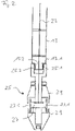
- the pressure medium hose 13 is connected to a cleaning head 25 at an opposite end 13.1. this is in 2 shown schematically.
- the length of the pressure medium hose 13 depends on the length of a hose filter to be cleaned.
- the end 13.1 of the pressure medium hose 13 has an external thread 13.2 which meshes with an internal thread 25.2 of a cover 25.1. This way he can Cleaning head 25 are screwed onto the end of the pressure medium hose 13 13.1.
- the screw connection is fixed but detachable and well suited for an operationally reliable connection.
- a rotor 27 is formed in the cleaning head 25, which has at least one cleaning bore 27.1, which is aligned essentially radially and directs a cleaning jet of the pressure medium in the direction of an inner wall of the bag filter.
- the drive shaft 23 is connected to the rotor 27 and drives the rotor 27 and thus the cleaning hole 27.1 to rotate when the drive device 15 is switched on.
- the rotor 27 is largely covered on the outside by a jacket 29 of the cleaning head 25, so that the rotating components of the cleaning head 25 are not exposed. This prevents physical contact between the rotor 27 and a support basket arranged in the bag filter for clamping the bag filter.
- a recess 30 is formed in the jacket 29, which is aligned with the cleaning hole 27.1 when both are aligned.
- the drive device 15 ⁇ is arranged in the cleaning head 25 ⁇ . This replaces there the drive device 15 in the control box 3.
- the pressure medium pipe 11 does not have to have a pipe extension 11.3 with the sealing device 11.4, at least this is then tightly closed by a closure (not shown).
- the drive device 15 ⁇ is integrated in the cleaning head 25 ⁇ .
- the cleaning head 25 ⁇ in 3 has below the rotor 27 ⁇ in a space 33 ⁇ enclosed by an end cap 31 ⁇ on the drive device 15 ⁇ , which is connected via the drive shaft 23 ⁇ to the rotor 27 ⁇ .
- the drive shaft 23 * does not have to, as in FIG 2 and 3 described and does not belong to the invention, can be flexible, but can also be rigid.
- An accumulator is used here as a voltage source 35 ⁇ .
- a controller 37 ⁇ is arranged with which the drive device 15 ⁇ can be controlled.
- the drive device 15 * is an electric motor.
- the controller 37 ⁇ is via a radio link with the Control device 19 connected so that the drive device 15 ⁇ from the outside can be served. Alternatively, wired connections between the controller 37 ⁇ and the drive device 15 ⁇ can be used.
Landscapes
- Chemical & Material Sciences (AREA)
- Chemical Kinetics & Catalysis (AREA)
- Engineering & Computer Science (AREA)
- Mechanical Engineering (AREA)
- Filtering Of Dispersed Particles In Gases (AREA)
- Cleaning In General (AREA)
Description
- Die vorliegende Erfindung betrifft eine Reinigungsvorrichtung für in einem Filterboden hängende Schlauchfilter, mit einem Reinigungskopf, der an einem Ende über einen Druckmittelschlauch mit einer Druckmittelquelle verbunden ist und eine Reinigungsbohrung aufweist, die um eine Hauptachse des Reinigungskopfes herum in Drehung versetzt werden kann und durch die Druckmittel austritt, wobei in dem Reinigungskopf eine Antriebseinrichtung angeordnet ist, welche die Reinigungsbohrung in Drehung versetzt, und mit einer Steuereinrichtung zur Steuerung von Betriebsparametern und der Antriebseinrichtung.
- Eine solche Reinigungsvorrichtung ist aus
WO 2010/119899 A1 bekannt. In diesem Stand der Technik ist beschrieben, dass eine motorische Antriebseinrichtung in oder an einem Reinigungskopf angebracht ist und sich während eines Reinigungsvorgangs innerhalb eines zu reinigenden Objekts befindet. Der Reinigungskopf weist ein erstes Ende auf, das mit einem Druckmittelrohr verbunden ist und weist ein entgegengesetztes, zweites oder freies Ende auf, das eine Stirnseite des Reinigungskopfes bildet. Die Antriebseinrichtung ist in einem Gehäuse einer Reinigungseinrichtung in der Nähe des ersten Endes des Reinigungskopfes angeordnet. Das Gehäuse weist unmittelbar vor dem Reinigungskopf ein Lager auf, das einen Durchgang der Antriebswelle zulässt. Auch wenn sich in dem Schlauchfilter die Reingasseite befindet und der größte Teil der Verschmutzung am Schlauchfilter außen anhaftet, tritt bei der intensiven Abreinigung mittels Druckbeaufschlagung von innen immer auch ein Staubanteil durch den Filter in das Innere des Schlauchfilters und wird dort nach oben abgesaugt. Der bei einer Reinigung auch im Inneren eines Schlauchfilters anfallende Staub wird an einen Eingang des Schlauchfilters, also stromaufwärts über einen Auslass nach außen abgeführt. Der von der Reinigungseinrichtung erzeugte Staub wird somit in unmittelbarer Nähe des Lagers erzeugt und bei seinem Transport nach oben an dem Gehäuse vorbeigeführt. Die am ersten Ende des Reinigungskopfes liegende Antriebseinrichtung ist während eines Reinigungsvorgangs daher einer im Einzelfall nicht unerheblichen Staubbelastung ausgesetzt. Dies wiederum führt dazu, dass Staub in das Gehäuse eindringt und die Funktion der Antriebseinrichtung und der in dem Gehäuse zudem angeordneten Bauelemente beeinträchtigt oder versagen lässt. - Reinigungsvorrichtungen ohne Antriebseinrichtung sind zum Beispiel aus
EP 1 543 872 A1 ,EP 1 932 577 A1 oderEP 2 409 788 A2 bekannt. - Die in dem vorgenannten Stand der Technik offenbarten Reinigungsvorrichtungen werden eingesetzt, um Schlauchfilter zu reinigen. Die Rohseite eines solchen mit den Reinigungsvorrichtungen des Standes der Technik zu reinigenden Schlauchfilters liegt außen und die Reinseite im Inneren des Schlauchfilters. Es strömt also die verunreinigte Luft von außen durch das Filtermaterial des Schlauchfilters nach innen und wird dort abgeführt. Beim Durchströmen des Schlauchfilters bleiben die Verunreinigungen der Luft in dem Filtermaterial hängen, so dass die Luft im Inneren des Schlauchfilters gereinigt ist. Mit der Zeit setzt sich die Außenseite solcher Schlauchfilter demnach mit den Verunreinigungen zu. Das bedeutet, dass sich das Filtergut überwiegend auf der Außenseite ablagert und zunehmend die Durchlässigkeit des Filtermaterials vermindert.
- Durch das Zusetzen von Schlauchfiltern über die Betriebszeit verringert sich deren Filterleistung. Es ist daher in vorbestimmten zeitlichen Abständen erforderlich, solche Schlauchfilter zu reinigen, um stets eine gute Filterleistung sicherzustellen.
- Zu diesem Zweck wird in vorbestimmten zeitlichen Abständen entweder im laufenden Betrieb der Filteranlage oder aber während eines Stillstands ein Reinigungskopf in das Innere des Schlauchfilters, also auf der Reinseite, eingeführt. Der Reinigungskopf ist über einen Druckmittelschlauch mit einer Druckmittelquelle verbunden, die sich irgendwo außerhalb befindet. Die Schlauchfilter hängen mit einem offenen Ende in einer Öffnung eines Filterbodens, auf dem zum Beispiel die Druckmittelquelle platziert werden kann. Die Druckmittelquelle weist eine Steuereinrichtung auf, mit deren Hilfe der Druck des Druckmittels einstellbar ist. Der Reinigungskopf weist wiederum wenigstens eine radiale Bohrung auf, aus der das Druckmittel in radialer Richtung aus dem Reinigungskopf austreten kann und gegebenenfalls auf die Innenseite des Schlauchfilters auftrifft. Bei nicht-rotierenden Reinigungsköpfen bildet die Reinigungsbohrung zum Beispiel eine Ringdüse, so dass ein umfänglicher Reinigungsstrahl austreten kann, der sich bei einer Bewegung des Reinigungskopfes entlang der Längsachse des Schlauchfilters dazu führt, dass sich das Filtermaterial des Schlauchfilters in Bewegungsrichtung wellenartig nach außen wölbt. Dadurch fällt das Filtergut von der Außenseite des Schlauchfilters ab.
- Die Aufgabe der vorliegenden Erfindung ist daher, eine Reinigungsvorrichtung der eingangs genannten Art derart weiterzubilden, dass diese in einem großen Anwendungsbereich stets optimal gesteuert werden kann.
- Die Aufgabe wird erfindungsgemäß dadurch gelöst, dass die Antriebseinrichtung in einem Raum angeordnet ist, der ein freies Ende des mit dem Druckmittelschlauch verbundenen und in den hängenden Schlauchfilter eingeführten Reinigungskopfes bildet und durch eine Endkappe umschlossen ist.
- Ein weiterer Vorteil der vorliegenden Erfindung ist es, dass der Reinigungskopf einen Rotor aufweist, in dem die Reinigungsbohrung ausgebildet ist. Durch diese Maßnahme ist sichergestellt, dass sich nicht der gesamte Reinigungskopf drehen muss, sondern nur ein Bauteil desselben. Es ist daher möglich, den Rotor nach außen abzudecken und dadurch zu verhindern, dass drehende Teile mit einem sich zwischen dem Reinigungskopf und dem Filtermaterial angeordneten Stützkorb kollidieren.
- Ein weiterer Vorteil der vorliegenden Erfindung ist, dass der Druckmittelchlauch an einem dem Reinigungskopf entgegengesetzten Ende an ein Druckrohr gekuppelt ist. Die Anordnung eines Druckrohrs zwischen dem Druckmittelschlauch und der Druckmittelquelle ermöglicht, in einfacher Weise, mechanische Bauteile und Steuerelemente mit dem Druckmittelschlauch zu verbinden.
- Weitere Vorteile der vorliegenden Erfindung ergeben sich aus den weiteren Merkmalen der weiteren Unteransprüche.
- Eine Ausführungsform der vorliegenden Erfindung wird im Folgenden näher dargestellt. Zum Verständnis der gesamten Funktionsweise wird auch eine nicht zur vorliegenden Erfindung gehörende Ausführungsform beschrieben. Es zeigen:
-
Fig. 1 eine schematische Darstellung einer nicht zur vorliegenden Erfindung gehörenden Ausführungsform einer Reinigungsvorrichtung; -
Fig. 2 eine schematische Darstellung der nicht zur vorliegenden Erfindung gehörenden Ausführungsform eines Reinigungskopfes und eines daran ansetzenden Druckmittelschlauchs der Reinigungsvorrichtung ausFig.1 ; und -
Fig. 3 eine schematische Darstellung eines Reinigungskopfes und eines daran ansetzenden Druckmittelschlauchs als Teil der erfindungsgemäßen Reinigungsvorrichtung. - In
Fig. 1 ist schematisch ein Teil einer Reinigungsvorrichtung 1 in einer nicht zur vorliegenden Erfindung gehörenden Ausführungsform dargestellt. Das Teil wird als Steuerkiste 3 bezeichnet und ist außerhalb eines zu reinigenden Filterschlauchs (nicht dargestellt) positioniert. Zu diesem Zweck weist die Steuerkiste 3 ein Gehäuse 5 auf, das hier nur schematisch als rechteckige Linie dargestellt ist. An dem Gehäuse 5 sind bodenseitig Füße 5.1 und deckenseitig ein Deckel 5.2 vorgesehen. An einer ersten Seitenwand 5.3 weist das Gehäuse 5 einen ersten Kupplungsanschluss 7 auf. An einer zweiten Seitenwand 5.4 weist das Gehäuse 5 einen zweiten Kupplungsanschluss 9 auf. Im Inneren des Gehäuses 5 befindet sich ein Druckrohr 11, das sich von dem Kupplungsanschluss 7 zum zweiten Kupplungsanschluss 9 erstreckt und im Wesentlichen krümmungsfrei verläuft. Der zweite Kupplungsanschluss 9 dient als Anschluss an eine Druckmittelquelle (nicht dargestellt) und der erste Kupplungsanschluss 7 dient zum Anschluss eines Druckmittelschlauchs 13. Als Druckmittelquelle kann zum Beispiel ein Kompressor dienen. In diesem Fall ist das Druckmittel Umgebungsluft. In anderen Ausführungsformen können aber auch andere zur Reinigung geeignete Gase, z.B. Inertgase, verwendet werden. - An dem Druckmittelrohr 11 ist in der Nähe des zweiten Kupplungsanschlusses 9 ein Absperrhahn 11.1 angeordnet. Mit diesem Absperrhahn 11.1 kann ein von der Druckmittelquelle über den zweiten Druckmittelanschluss 9 strömendes Druckmittel abgesperrt werden. Stromabwärts in Richtung des ersten Kupplungsanschlusses 7 ist an dem Druckmittelrohr 11 ein Steuerventil 11.2 angeordnet, das öffnen und schließen kann. Zwischen dem Steuerventil 11.2 und dem ersten Kupplungsanschluss 7 ist ein Rohransatz 11.3 vorgesehen, der an einem freien Ende ein Dichtungselement 11.4 aufweist, das ein Simmerring sein kann.
- Unterhalb des Druckmittelrohrs 11 ist in der Steuerkiste 3 eine Antriebseinrichtung 15 angeordnet. Bei der Antriebseinrichtung 15 handelt es sich in der dargestellten Ausführungsform um einen Elektromotor. Der Elektromotor ist über eine elektrische Verbindung 17 mit einer Steuereinrichtung 19 verbunden. Die Steuereinrichtung 19 ist eine Steuerbox mit Display (nicht dargestellt), mit der Betriebsparameter der Antriebseinrichtung 15, zum Beispiel Drehzahlen, eingestellt werden können. Die Steuereinrichtung 19 kann auch mit dem Steuerventil 11.2 verbunden sein, um auch die Betriebsparameter des Druckmittels einstellen zu können. In anderen Ausführungsformen können auch unabhängige Steuereinrichtungen für Druckmittel und Antrieb vorgesehen sein. Die Steuereinrichtung 19 ist wiederum über einen Spannungsversorgungsanschluss 21 mit einer Spannungsquelle, zum Beispiel Netzspannung, verbunden.
- Die Antriebseinrichtung 15 treibt eine Antriebswelle 23 an, die eine flexible Antriebswelle ist und über die Dichtungseinrichtung 11.4 und den Rohransatz 11.3 in den Druckmittelschlauch 13 eingeführt ist. Der Rohransatz 11.3 bzw. die Dichtungseinrichtung 11.4 dienen als Lager für die flexible Antriebswelle 23.
- Der Druckmittelschlauch 13 ist ein flexibler Schlauch, der üblicherweise für die Leitung von Druckmittel, z.B. Druckluft, verwendet wird. Der Druckmittelschlauch 13 ist an einem entgegengesetzten Ende 13.1 mit einem Reinigungskopf 25 verbunden. Dies ist in
Fig. 2 schematisch dargestellt. Die Länge des Druckmittelschlauchs 13 ist abhängig von der Länge eines zu reinigenden Schlauchfilters. - Das Ende 13.1 des Druckmittelschlauchs 13 weist ein Außengewinde 13.2 auf, das mit einem Innengewinde 25.2 eines Deckels 25.1 kämmt. Auf diese Weise kann der Reinigungskopf 25 auf das Ende 13.1 des Druckmittelschlauchs 13 geschraubt werden. Die Schraubverbindung ist fest aber lösbar und gut geeignet für eine betriebssichere Verbindung.
- In dem Reinigungskopf 25 ist ein Rotor 27 ausgebildet, der wenigstens eine Reinigungsbohrung 27.1 aufweist, die im Wesentlichen radial ausgerichtet ist und einen Reinigungsstrahl des Druckmittels in Richtung einer Innenwand des Schlauchfilters lenkt. Die Antriebswelle 23 ist mit dem Rotor 27 verbunden und treibt den Rotor 27 und somit die Reinigungsbohrung 27.1 zu einer Drehbewegung an, wenn die Antriebseinrichtung 15 eingeschaltet ist. Der Rotor 27 ist nach außen von einem Mantel 29 des Reinigungskopfes 25 weitestgehend abgedeckt, so dass die drehenden Bauteile des Reinigungskopfes 25 nicht freiliegen. Dadurch wird ein Berührungskontakt zwischen Rotor 27 und einem im Schlauchfilter zum Aufspannen des Schlauchfilters angeordneten Stützkorb verhindert. In der dargestellten Ausführungsform ist im Mantel 29 eine Ausnehmung 30 ausgebildet, die mit der Reinigungsbohrung 27.1 fluchtet, wenn beide gleichgerichtet sind. Dadurch können bei kontinuierlichem Druckmittelstrom Impulse erzeugt werden, welche die Reinigungswirkung noch verbessern.
- In
Fig. 3 ist die erfindungsgemäße Ausführungsform der erfindungsgemäßen Reinigungsvorrichtung 1 dargestellt. Der Unterschied zu der inFig 1 undFig. 2 beschriebenen nicht zu der Erfindung gehörenden Ausführungsform liegt im Wesentlichen nur in der Anordnung der Antriebseinrichtung. Aus diesem Grunde werden die für die erfindungsgemäße Ausführungsform relevanten Bauteile mit den gleichen Bezugszeichen versehen, die lediglich zusätzlich ein "∗" aufweisen. Bauteile, die in der erfindungsgemäßen Ausführungsform und in der in denFiguren 1 und2 beschriebenen Ausführungsform Verwendung finden und identisch sind behalten das inFig. 1 undFig. 2 verwendete Bezugszeichen. Der Reinigungskopf 25 ∗ ist in den nicht beschriebenen Bauteilen und Konstruktionen identisch mit dem Reinigungskopf 25 . - In
Fig. 3 ist die Antriebseinrichtung 15∗ im Reinigungskopf 25 ∗ angeordnet. Diese ersetzt dort die Antriebseinrichtung 15 in der Steuerkiste 3. Das Druckmittelrohr 11 muss dann in der erfindungsgemäßen Ausführungsform auch keinen Rohransatz 11.3 mit der Dichtungseinrichtung 11.4 aufweisen, zumindest ist dieser dann durch einen Verschluss (nicht dargestellt) dicht verschlossen. In der erfindungsgemäßen Ausführungsform ist die Antriebseinrichtung 15∗ im Reinigungskopf 25 ∗ integriert. - Der Reinigungskopf 25 ∗ in
Fig. 3 weist unterhalb des Rotors 27∗ in einem durch eine Endkappe 31∗ umschlossenen Raum 33∗ die Antriebseinrichtung 15∗ auf, die über die Antriebswelle 23 ∗ mit dem Rotor 27∗ verbunden ist. Die Antriebswelle 23 ∗ muss in der erfindungsgemäßen Ausführungsform nicht, wie in der inFig. 2 undFig. 3 beschriebenen und nicht zur Erfindung gehörenden Ausführungsform, flexibel ausgebildet sein, sondern kann auch starr sein. Als Spannungsquelle 35∗ dient hier ein Akkumulator. In dem Raum 33∗ ist ein Regler 37∗ angeordnet, mit dem die Antriebseinrichtung 15∗ gesteuert werden kann. Auch die Antriebseinrichtung 15∗ ist ein Elektromotor. Der Regler 37∗ ist über eine Funkverbindung mit der Steuereinrichtung 19 verbunden, so dass die Antriebseinrichtung 15∗ von außen bedient werden kann. Alternativ sind auch kabelgebundene Verbindungen zwischen dem Regler 37∗ und der Antriebseinrichtung 15∗ einsetzbar. -
- 1
- Reinigungsvorrichtung
- 3
- Steuerkiste
- 5
- Gehäuse
- 5.1
- Füße
- 5.2
- Deckel
- 5.3
- erste Seitenwand
- 5.4
- zweite Seitenwand
- 7
- erster Kupplungsanschluss
- 9
- zweiter Kupplungsanschluss
- 11
- Druckmittelrohr
- 11.1
- Absperrhahn
- 11.2
- Steuerventil
- 11.3
- Rohransatz
- 11.4
- Dichtungselement
- 13
- Druckmittelschlauch
- 13.1
- Ende des Druckmittelschlauchs
- 13.2
- Außengewinde
- 15
- Antriebseinrichtung
- 15∗
- Antriebseinrichtung
- 17
- elektrische Verbindung
- 19
- Steuereinrichtung
- 21
- Spannungsversorgungsanschluss
- 23
- flexible Antriebswelle
- 23∗
- Antriebswelle
- 25
- Reinigungskopf
- 25∗
- Reinigungskopf
- 25.1
- Deckel
- 25.2
- Innengewinde
- 27
- Rotor
- 27∗
- Rotor
- 27.1
- Reinigungsbohrung
- 27.1∗
- Reinigungsbohrung
- 29
- Mantel
- 30
- Ausnehmung
- 31∗
- Endkappe
- 33∗
- Raum
- 35∗
- Spannungsquelle
- 37∗
- Regler
Claims (8)
- Reinigungsvorrichtung für in einem Filterboden hängende Schlauchfilter, mit einem Reinigungskopf (25∗), der an einem Ende über einen Druckmittelschlauch (13) mit einer Druckmittelquelle verbunden ist und eine Reinigungsbohrung (27.1∗) aufweist, die um eine Hauptachse des Reinigungskopfes (25∗) herum in Drehung versetzt werden kann und durch die Druckmittel austritt, wobei in dem Reinigungskopf (25∗) eine Antriebseinrichtung (15∗) angeordnet ist welche die Reinigungsbohrung (27.2∗) in Drehung versetzt, und mit einer Steuereinrichtung (19) zum Steuern von Betriebsparametern und der Antriebseinrichtung (15∗)
dadurch gekennzeichnet,
dass die Antriebseinrichtung (15∗) in einem Raum (33∗) angeordnet ist, der ein freies Ende des mit dem Druckmittelschlauch (13) verbundenen und in den hängenden Schlauchfilter eingeführten Reinigungskopfes (25∗) bildet und durch eine Endkappe (31∗) umschlossen ist. - Reinigungsvorrichtung nach Anspruch 1,
dadurch gekennzeichnet,
dass der Reinigungskopf (25∗) einen Rotor (27∗) aufweist, in dem die Reinigungsbohrung (27.1∗) ausgebildet ist. - Reinigungsvorrichtung nach Anspruch 2,
dadurch gekennzeichnet,
dass der Druckmittelchlauch (13) an einem dem Reinigungskopf (25∗) entgegengesetzten Ende an ein Druckrohr (11) gekuppelt ist. - Reinigungsvorrichtung nach Anspruch 3,
dadurch gekennzeichnet,
dass in dem Raum (33∗) ein Regler (37∗) angeordnet ist. - Reinigungsvorrichtung nach Anspruch 4,
dadurch gekennzeichnet,
dass der Regler (37∗) über eine Funkverbindung mit der Steuereinrichtung (19) verbunden ist. - Reinigungsvorrichtung nach Anspruch 4 oder 5,
dadurch gekennzeichnet,
dass der Regler (37∗) mit einer Spannungsversorgung verbunden ist - Reinigungsvorrichtung nach Anspruch 6,
dass die Spannungsversorgung einen Akkumulator als Spannungsquelle (35∗) umfasst. - Reinigungsvorrichtung nach einem der Ansprüche 3 bis 7,
dadurch gekennzeichnet,
dass das Druckrohr (11) ein Steuerventil (11.2) aufweist.
Priority Applications (4)
| Application Number | Priority Date | Filing Date | Title |
|---|---|---|---|
| EP20000066.9A EP3689438B1 (de) | 2018-12-07 | 2018-12-07 | Reinigungsvorrichtung für schlauchfilter |
| EP18000949.0A EP3662985B1 (de) | 2018-12-07 | 2018-12-07 | Reinigungsvorrichtung für schlauchfilter |
| US16/221,929 US20200179861A1 (en) | 2018-12-07 | 2018-12-17 | Cleaning system for bag filters |
| ZA2019/07907A ZA201907907B (en) | 2018-12-07 | 2019-11-28 | Cleaning apparatus for bag filters |
Applications Claiming Priority (1)
| Application Number | Priority Date | Filing Date | Title |
|---|---|---|---|
| EP18000949.0A EP3662985B1 (de) | 2018-12-07 | 2018-12-07 | Reinigungsvorrichtung für schlauchfilter |
Related Child Applications (2)
| Application Number | Title | Priority Date | Filing Date |
|---|---|---|---|
| EP20000066.9A Division EP3689438B1 (de) | 2018-12-07 | 2018-12-07 | Reinigungsvorrichtung für schlauchfilter |
| EP20000066.9A Division-Into EP3689438B1 (de) | 2018-12-07 | 2018-12-07 | Reinigungsvorrichtung für schlauchfilter |
Publications (2)
| Publication Number | Publication Date |
|---|---|
| EP3662985A1 EP3662985A1 (de) | 2020-06-10 |
| EP3662985B1 true EP3662985B1 (de) | 2022-05-18 |
Family
ID=64664005
Family Applications (2)
| Application Number | Title | Priority Date | Filing Date |
|---|---|---|---|
| EP18000949.0A Active EP3662985B1 (de) | 2018-12-07 | 2018-12-07 | Reinigungsvorrichtung für schlauchfilter |
| EP20000066.9A Active EP3689438B1 (de) | 2018-12-07 | 2018-12-07 | Reinigungsvorrichtung für schlauchfilter |
Family Applications After (1)
| Application Number | Title | Priority Date | Filing Date |
|---|---|---|---|
| EP20000066.9A Active EP3689438B1 (de) | 2018-12-07 | 2018-12-07 | Reinigungsvorrichtung für schlauchfilter |
Country Status (3)
| Country | Link |
|---|---|
| US (1) | US20200179861A1 (de) |
| EP (2) | EP3662985B1 (de) |
| ZA (1) | ZA201907907B (de) |
Families Citing this family (3)
| Publication number | Priority date | Publication date | Assignee | Title |
|---|---|---|---|---|
| CN114226351B (zh) * | 2021-08-16 | 2024-01-30 | 重庆大学 | 一种复合材料干切加工复杂多工况自适应除尘装置 |
| CN116672817B (zh) * | 2023-05-19 | 2026-02-06 | 无锡红旗除尘设备有限公司 | 一种脉冲喷吹滤袋式除尘器维护方法 |
| CN118289489B (zh) * | 2024-05-07 | 2024-09-10 | 江苏禾泰玻璃科技有限公司 | 一种微纤维玻璃棉生产用玻璃料块输送装置 |
Family Cites Families (7)
| Publication number | Priority date | Publication date | Assignee | Title |
|---|---|---|---|---|
| JP4473401B2 (ja) * | 2000-03-17 | 2010-06-02 | 株式会社Ihi環境エンジニアリング | バグフィルターの濾布清掃用ノズル装置 |
| PT1543872E (pt) | 2003-12-10 | 2007-01-31 | Christian Reining | Dispositivo de filtro com uma mangueira de filtro e uma disposição de limpeza para a mangueira de filtro |
| EP1932577B1 (de) | 2006-11-15 | 2009-01-14 | Christian Reining | Reinigungsvorrichtung mit Reinigungskopf und Verfahren zur Reinigung von Schlauchfiltern |
| JP2010247138A (ja) * | 2009-04-16 | 2010-11-04 | Hirohito Ito | フィルタ清掃用ノズルシステム |
| ES2561220T3 (es) | 2010-07-21 | 2016-02-25 | Christian Reining | Campana de aspiración para un dispositivo de limpieza móvil y un sistema de limpieza móvil con una campana de aspiración de este tipo, así como método de limpieza |
| DE202013009510U1 (de) * | 2013-06-01 | 2013-12-19 | Stephan Spanner | Düsenkopf und Reinigungsvorrichtung mit einem solchen Düsenkopf |
| WO2016006742A1 (ko) * | 2014-07-11 | 2016-01-14 | 이충중 | 이동식 필터 백 재생장치 |
-
2018
- 2018-12-07 EP EP18000949.0A patent/EP3662985B1/de active Active
- 2018-12-07 EP EP20000066.9A patent/EP3689438B1/de active Active
- 2018-12-17 US US16/221,929 patent/US20200179861A1/en not_active Abandoned
-
2019
- 2019-11-28 ZA ZA2019/07907A patent/ZA201907907B/en unknown
Also Published As
| Publication number | Publication date |
|---|---|
| EP3689438A1 (de) | 2020-08-05 |
| EP3689438B1 (de) | 2021-09-01 |
| ZA201907907B (en) | 2022-03-30 |
| EP3662985A1 (de) | 2020-06-10 |
| US20200179861A1 (en) | 2020-06-11 |
Similar Documents
| Publication | Publication Date | Title |
|---|---|---|
| DE2626008C3 (de) | Luftreiniger | |
| EP2864050B1 (de) | Vorrichtung und verfahren zum abscheiden magnetisierbarer verunreinigungen aus strömenden fluiden | |
| EP3662985B1 (de) | Reinigungsvorrichtung für schlauchfilter | |
| DE2006685A1 (de) | Selbstreinigendes Filter | |
| EP3621717B1 (de) | Filtervorrichtung | |
| EP2468379B1 (de) | Filtervorrichtung | |
| EP1438527A1 (de) | Vorrichtung zum erzeugen eines pulsierenden fluidstroms | |
| DE112012004992T5 (de) | Filtervorrichtung unter Verwendung druckbeaufschlagter Reversierreinigung mittels einer Filtertrommel | |
| EP2468380B1 (de) | Filtervorrichtung | |
| EP0517945A1 (de) | Rückspülbares Filtergerät | |
| DE102014219569B4 (de) | Wasserfiltereinrichtung mit rückspülbarem Wasserfilter mit Fließgeschwindigkeitsreduktion und Verfahren zum Rückspülen eines Wasserfilters | |
| EP1946812A1 (de) | Rückspülbarer Filter | |
| DE102014012032A1 (de) | Verfahren und Vorrichtung zum Filtrieren einer Flüssigkeit | |
| EP3160711B1 (de) | Schmelzefilteranordnung mit rückspül-schneckenfördereinrichtung | |
| EP2039410A1 (de) | Filtervorrichtung | |
| EP3017855A1 (de) | Filtervorrichtung und betriebsverfahren hierzu | |
| DE102009035895B4 (de) | Filteranordnung | |
| DE3621724A1 (de) | Vollautomatisches rueckspuelfilter fuer fluessige medien | |
| DE102010022928A1 (de) | Verfahren zur Reinigung einer Filterpatrone und Filterpatronen-Reinigungsvorrichtung sowie Abscheider mit einer solchen Einrichtung | |
| DE10245013A1 (de) | Filterzentrifuge | |
| DE202006004529U1 (de) | Filtereinsatz mit Verschluss für zweite Filterkammer | |
| EP4115964B1 (de) | Filtervorrichtung | |
| DE3046388C2 (de) | Spaltfilter für Flüssigkeiten | |
| DE10126048A1 (de) | Vorrichtung zum Reinigen staubbeladener Rohgase | |
| EP1851468B1 (de) | Ventilmodul |
Legal Events
| Date | Code | Title | Description |
|---|---|---|---|
| PUAI | Public reference made under article 153(3) epc to a published international application that has entered the european phase |
Free format text: ORIGINAL CODE: 0009012 |
|
| STAA | Information on the status of an ep patent application or granted ep patent |
Free format text: STATUS: THE APPLICATION HAS BEEN PUBLISHED |
|
| AK | Designated contracting states |
Kind code of ref document: A1 Designated state(s): AL AT BE BG CH CY CZ DE DK EE ES FI FR GB GR HR HU IE IS IT LI LT LU LV MC MK MT NL NO PL PT RO RS SE SI SK SM TR |
|
| AX | Request for extension of the european patent |
Extension state: BA ME |
|
| STAA | Information on the status of an ep patent application or granted ep patent |
Free format text: STATUS: REQUEST FOR EXAMINATION WAS MADE |
|
| 17P | Request for examination filed |
Effective date: 20201209 |
|
| RBV | Designated contracting states (corrected) |
Designated state(s): AL AT BE BG CH CY CZ DE DK EE ES FI FR GB GR HR HU IE IS IT LI LT LU LV MC MK MT NL NO PL PT RO RS SE SI SK SM TR |
|
| STAA | Information on the status of an ep patent application or granted ep patent |
Free format text: STATUS: EXAMINATION IS IN PROGRESS |
|
| 17Q | First examination report despatched |
Effective date: 20210303 |
|
| GRAP | Despatch of communication of intention to grant a patent |
Free format text: ORIGINAL CODE: EPIDOSNIGR1 |
|
| STAA | Information on the status of an ep patent application or granted ep patent |
Free format text: STATUS: GRANT OF PATENT IS INTENDED |
|
| INTG | Intention to grant announced |
Effective date: 20211221 |
|
| GRAS | Grant fee paid |
Free format text: ORIGINAL CODE: EPIDOSNIGR3 |
|
| GRAA | (expected) grant |
Free format text: ORIGINAL CODE: 0009210 |
|
| STAA | Information on the status of an ep patent application or granted ep patent |
Free format text: STATUS: THE PATENT HAS BEEN GRANTED |
|
| AK | Designated contracting states |
Kind code of ref document: B1 Designated state(s): AL AT BE BG CH CY CZ DE DK EE ES FI FR GB GR HR HU IE IS IT LI LT LU LV MC MK MT NL NO PL PT RO RS SE SI SK SM TR |
|
| REG | Reference to a national code |
Ref country code: GB Ref legal event code: FG4D Free format text: NOT ENGLISH |
|
| REG | Reference to a national code |
Ref country code: CH Ref legal event code: EP |
|
| REG | Reference to a national code |
Ref country code: IE Ref legal event code: FG4D Free format text: LANGUAGE OF EP DOCUMENT: GERMAN |
|
| REG | Reference to a national code |
Ref country code: DE Ref legal event code: R096 Ref document number: 502018009688 Country of ref document: DE |
|
| REG | Reference to a national code |
Ref country code: AT Ref legal event code: REF Ref document number: 1492822 Country of ref document: AT Kind code of ref document: T Effective date: 20220615 |
|
| REG | Reference to a national code |
Ref country code: LT Ref legal event code: MG9D |
|
| REG | Reference to a national code |
Ref country code: NL Ref legal event code: MP Effective date: 20220518 |
|
| PG25 | Lapsed in a contracting state [announced via postgrant information from national office to epo] |
Ref country code: SE Free format text: LAPSE BECAUSE OF FAILURE TO SUBMIT A TRANSLATION OF THE DESCRIPTION OR TO PAY THE FEE WITHIN THE PRESCRIBED TIME-LIMIT Effective date: 20220518 Ref country code: PT Free format text: LAPSE BECAUSE OF FAILURE TO SUBMIT A TRANSLATION OF THE DESCRIPTION OR TO PAY THE FEE WITHIN THE PRESCRIBED TIME-LIMIT Effective date: 20220919 Ref country code: NO Free format text: LAPSE BECAUSE OF FAILURE TO SUBMIT A TRANSLATION OF THE DESCRIPTION OR TO PAY THE FEE WITHIN THE PRESCRIBED TIME-LIMIT Effective date: 20220818 Ref country code: NL Free format text: LAPSE BECAUSE OF FAILURE TO SUBMIT A TRANSLATION OF THE DESCRIPTION OR TO PAY THE FEE WITHIN THE PRESCRIBED TIME-LIMIT Effective date: 20220518 Ref country code: LT Free format text: LAPSE BECAUSE OF FAILURE TO SUBMIT A TRANSLATION OF THE DESCRIPTION OR TO PAY THE FEE WITHIN THE PRESCRIBED TIME-LIMIT Effective date: 20220518 Ref country code: HR Free format text: LAPSE BECAUSE OF FAILURE TO SUBMIT A TRANSLATION OF THE DESCRIPTION OR TO PAY THE FEE WITHIN THE PRESCRIBED TIME-LIMIT Effective date: 20220518 Ref country code: GR Free format text: LAPSE BECAUSE OF FAILURE TO SUBMIT A TRANSLATION OF THE DESCRIPTION OR TO PAY THE FEE WITHIN THE PRESCRIBED TIME-LIMIT Effective date: 20220819 Ref country code: FI Free format text: LAPSE BECAUSE OF FAILURE TO SUBMIT A TRANSLATION OF THE DESCRIPTION OR TO PAY THE FEE WITHIN THE PRESCRIBED TIME-LIMIT Effective date: 20220518 Ref country code: ES Free format text: LAPSE BECAUSE OF FAILURE TO SUBMIT A TRANSLATION OF THE DESCRIPTION OR TO PAY THE FEE WITHIN THE PRESCRIBED TIME-LIMIT Effective date: 20220518 Ref country code: BG Free format text: LAPSE BECAUSE OF FAILURE TO SUBMIT A TRANSLATION OF THE DESCRIPTION OR TO PAY THE FEE WITHIN THE PRESCRIBED TIME-LIMIT Effective date: 20220818 |
|
| PG25 | Lapsed in a contracting state [announced via postgrant information from national office to epo] |
Ref country code: RS Free format text: LAPSE BECAUSE OF FAILURE TO SUBMIT A TRANSLATION OF THE DESCRIPTION OR TO PAY THE FEE WITHIN THE PRESCRIBED TIME-LIMIT Effective date: 20220518 Ref country code: PL Free format text: LAPSE BECAUSE OF FAILURE TO SUBMIT A TRANSLATION OF THE DESCRIPTION OR TO PAY THE FEE WITHIN THE PRESCRIBED TIME-LIMIT Effective date: 20220518 Ref country code: LV Free format text: LAPSE BECAUSE OF FAILURE TO SUBMIT A TRANSLATION OF THE DESCRIPTION OR TO PAY THE FEE WITHIN THE PRESCRIBED TIME-LIMIT Effective date: 20220518 Ref country code: IS Free format text: LAPSE BECAUSE OF FAILURE TO SUBMIT A TRANSLATION OF THE DESCRIPTION OR TO PAY THE FEE WITHIN THE PRESCRIBED TIME-LIMIT Effective date: 20220918 |
|
| PG25 | Lapsed in a contracting state [announced via postgrant information from national office to epo] |
Ref country code: SM Free format text: LAPSE BECAUSE OF FAILURE TO SUBMIT A TRANSLATION OF THE DESCRIPTION OR TO PAY THE FEE WITHIN THE PRESCRIBED TIME-LIMIT Effective date: 20220518 Ref country code: SK Free format text: LAPSE BECAUSE OF FAILURE TO SUBMIT A TRANSLATION OF THE DESCRIPTION OR TO PAY THE FEE WITHIN THE PRESCRIBED TIME-LIMIT Effective date: 20220518 Ref country code: RO Free format text: LAPSE BECAUSE OF FAILURE TO SUBMIT A TRANSLATION OF THE DESCRIPTION OR TO PAY THE FEE WITHIN THE PRESCRIBED TIME-LIMIT Effective date: 20220518 Ref country code: EE Free format text: LAPSE BECAUSE OF FAILURE TO SUBMIT A TRANSLATION OF THE DESCRIPTION OR TO PAY THE FEE WITHIN THE PRESCRIBED TIME-LIMIT Effective date: 20220518 Ref country code: DK Free format text: LAPSE BECAUSE OF FAILURE TO SUBMIT A TRANSLATION OF THE DESCRIPTION OR TO PAY THE FEE WITHIN THE PRESCRIBED TIME-LIMIT Effective date: 20220518 Ref country code: CZ Free format text: LAPSE BECAUSE OF FAILURE TO SUBMIT A TRANSLATION OF THE DESCRIPTION OR TO PAY THE FEE WITHIN THE PRESCRIBED TIME-LIMIT Effective date: 20220518 |
|
| REG | Reference to a national code |
Ref country code: DE Ref legal event code: R097 Ref document number: 502018009688 Country of ref document: DE |
|
| PLBE | No opposition filed within time limit |
Free format text: ORIGINAL CODE: 0009261 |
|
| STAA | Information on the status of an ep patent application or granted ep patent |
Free format text: STATUS: NO OPPOSITION FILED WITHIN TIME LIMIT |
|
| PG25 | Lapsed in a contracting state [announced via postgrant information from national office to epo] |
Ref country code: AL Free format text: LAPSE BECAUSE OF FAILURE TO SUBMIT A TRANSLATION OF THE DESCRIPTION OR TO PAY THE FEE WITHIN THE PRESCRIBED TIME-LIMIT Effective date: 20220518 |
|
| 26N | No opposition filed |
Effective date: 20230221 |
|
| PG25 | Lapsed in a contracting state [announced via postgrant information from national office to epo] |
Ref country code: SI Free format text: LAPSE BECAUSE OF FAILURE TO SUBMIT A TRANSLATION OF THE DESCRIPTION OR TO PAY THE FEE WITHIN THE PRESCRIBED TIME-LIMIT Effective date: 20220518 |
|
| REG | Reference to a national code |
Ref country code: CH Ref legal event code: PL |
|
| REG | Reference to a national code |
Ref country code: BE Ref legal event code: MM Effective date: 20221231 |
|
| PG25 | Lapsed in a contracting state [announced via postgrant information from national office to epo] |
Ref country code: LU Free format text: LAPSE BECAUSE OF NON-PAYMENT OF DUE FEES Effective date: 20221207 |
|
| PG25 | Lapsed in a contracting state [announced via postgrant information from national office to epo] |
Ref country code: LI Free format text: LAPSE BECAUSE OF NON-PAYMENT OF DUE FEES Effective date: 20221231 Ref country code: IE Free format text: LAPSE BECAUSE OF NON-PAYMENT OF DUE FEES Effective date: 20221207 Ref country code: CH Free format text: LAPSE BECAUSE OF NON-PAYMENT OF DUE FEES Effective date: 20221231 |
|
| PG25 | Lapsed in a contracting state [announced via postgrant information from national office to epo] |
Ref country code: BE Free format text: LAPSE BECAUSE OF NON-PAYMENT OF DUE FEES Effective date: 20221231 |
|
| PG25 | Lapsed in a contracting state [announced via postgrant information from national office to epo] |
Ref country code: IT Free format text: LAPSE BECAUSE OF FAILURE TO SUBMIT A TRANSLATION OF THE DESCRIPTION OR TO PAY THE FEE WITHIN THE PRESCRIBED TIME-LIMIT Effective date: 20220518 |
|
| PG25 | Lapsed in a contracting state [announced via postgrant information from national office to epo] |
Ref country code: HU Free format text: LAPSE BECAUSE OF FAILURE TO SUBMIT A TRANSLATION OF THE DESCRIPTION OR TO PAY THE FEE WITHIN THE PRESCRIBED TIME-LIMIT; INVALID AB INITIO Effective date: 20181207 |
|
| PG25 | Lapsed in a contracting state [announced via postgrant information from national office to epo] |
Ref country code: CY Free format text: LAPSE BECAUSE OF FAILURE TO SUBMIT A TRANSLATION OF THE DESCRIPTION OR TO PAY THE FEE WITHIN THE PRESCRIBED TIME-LIMIT Effective date: 20220511 |
|
| PG25 | Lapsed in a contracting state [announced via postgrant information from national office to epo] |
Ref country code: MK Free format text: LAPSE BECAUSE OF FAILURE TO SUBMIT A TRANSLATION OF THE DESCRIPTION OR TO PAY THE FEE WITHIN THE PRESCRIBED TIME-LIMIT Effective date: 20220511 |
|
| PG25 | Lapsed in a contracting state [announced via postgrant information from national office to epo] |
Ref country code: MC Free format text: LAPSE BECAUSE OF FAILURE TO SUBMIT A TRANSLATION OF THE DESCRIPTION OR TO PAY THE FEE WITHIN THE PRESCRIBED TIME-LIMIT Effective date: 20220518 |
|
| PG25 | Lapsed in a contracting state [announced via postgrant information from national office to epo] |
Ref country code: MC Free format text: LAPSE BECAUSE OF FAILURE TO SUBMIT A TRANSLATION OF THE DESCRIPTION OR TO PAY THE FEE WITHIN THE PRESCRIBED TIME-LIMIT Effective date: 20220518 |
|
| PG25 | Lapsed in a contracting state [announced via postgrant information from national office to epo] |
Ref country code: MT Free format text: LAPSE BECAUSE OF FAILURE TO SUBMIT A TRANSLATION OF THE DESCRIPTION OR TO PAY THE FEE WITHIN THE PRESCRIBED TIME-LIMIT Effective date: 20220511 |
|
| PG25 | Lapsed in a contracting state [announced via postgrant information from national office to epo] |
Ref country code: BG Free format text: LAPSE BECAUSE OF FAILURE TO SUBMIT A TRANSLATION OF THE DESCRIPTION OR TO PAY THE FEE WITHIN THE PRESCRIBED TIME-LIMIT Effective date: 20220518 |
|
| PG25 | Lapsed in a contracting state [announced via postgrant information from national office to epo] |
Ref country code: BG Free format text: LAPSE BECAUSE OF FAILURE TO SUBMIT A TRANSLATION OF THE DESCRIPTION OR TO PAY THE FEE WITHIN THE PRESCRIBED TIME-LIMIT Effective date: 20220518 |
|
| PG25 | Lapsed in a contracting state [announced via postgrant information from national office to epo] |
Ref country code: TR Free format text: LAPSE BECAUSE OF FAILURE TO SUBMIT A TRANSLATION OF THE DESCRIPTION OR TO PAY THE FEE WITHIN THE PRESCRIBED TIME-LIMIT Effective date: 20220518 |
|
| PGFP | Annual fee paid to national office [announced via postgrant information from national office to epo] |
Ref country code: DE Payment date: 20251209 Year of fee payment: 8 |
|
| PGFP | Annual fee paid to national office [announced via postgrant information from national office to epo] |
Ref country code: GB Payment date: 20251218 Year of fee payment: 8 |
|
| PGFP | Annual fee paid to national office [announced via postgrant information from national office to epo] |
Ref country code: AT Payment date: 20251215 Year of fee payment: 8 |
|
| PGFP | Annual fee paid to national office [announced via postgrant information from national office to epo] |
Ref country code: FR Payment date: 20251217 Year of fee payment: 8 |