EP3662985B1 - Dispositif de nettoyage pour filtre à manches - Google Patents
Dispositif de nettoyage pour filtre à manches Download PDFInfo
- Publication number
- EP3662985B1 EP3662985B1 EP18000949.0A EP18000949A EP3662985B1 EP 3662985 B1 EP3662985 B1 EP 3662985B1 EP 18000949 A EP18000949 A EP 18000949A EP 3662985 B1 EP3662985 B1 EP 3662985B1
- Authority
- EP
- European Patent Office
- Prior art keywords
- cleaning
- pressure medium
- cleaning head
- cleaning device
- hose
- Prior art date
- Legal status (The legal status is an assumption and is not a legal conclusion. Google has not performed a legal analysis and makes no representation as to the accuracy of the status listed.)
- Active
Links
- 238000004140 cleaning Methods 0.000 title claims description 83
- 239000000463 material Substances 0.000 description 7
- 230000008878 coupling Effects 0.000 description 5
- 238000010168 coupling process Methods 0.000 description 5
- 238000005859 coupling reaction Methods 0.000 description 5
- 239000000428 dust Substances 0.000 description 5
- 238000007789 sealing Methods 0.000 description 5
- 239000003570 air Substances 0.000 description 4
- 239000012530 fluid Substances 0.000 description 3
- 239000007789 gas Substances 0.000 description 2
- 238000000034 method Methods 0.000 description 2
- 239000012080 ambient air Substances 0.000 description 1
- 238000010276 construction Methods 0.000 description 1
- 239000000356 contaminant Substances 0.000 description 1
- 238000011109 contamination Methods 0.000 description 1
- 230000001419 dependent effect Effects 0.000 description 1
- 230000000694 effects Effects 0.000 description 1
- 239000012535 impurity Substances 0.000 description 1
- 239000011261 inert gas Substances 0.000 description 1
- 230000035699 permeability Effects 0.000 description 1
- 238000011144 upstream manufacturing Methods 0.000 description 1
Images


Classifications
-
- B—PERFORMING OPERATIONS; TRANSPORTING
- B01—PHYSICAL OR CHEMICAL PROCESSES OR APPARATUS IN GENERAL
- B01D—SEPARATION
- B01D46/00—Filters or filtering processes specially modified for separating dispersed particles from gases or vapours
- B01D46/02—Particle separators, e.g. dust precipitators, having hollow filters made of flexible material
- B01D46/04—Cleaning filters
-
- B—PERFORMING OPERATIONS; TRANSPORTING
- B01—PHYSICAL OR CHEMICAL PROCESSES OR APPARATUS IN GENERAL
- B01D—SEPARATION
- B01D41/00—Regeneration of the filtering material or filter elements outside the filter for liquid or gaseous fluids
- B01D41/04—Regeneration of the filtering material or filter elements outside the filter for liquid or gaseous fluids of rigid self-supporting filtering material
-
- B—PERFORMING OPERATIONS; TRANSPORTING
- B01—PHYSICAL OR CHEMICAL PROCESSES OR APPARATUS IN GENERAL
- B01D—SEPARATION
- B01D46/00—Filters or filtering processes specially modified for separating dispersed particles from gases or vapours
- B01D46/42—Auxiliary equipment or operation thereof
- B01D46/48—Removing dust other than cleaning filters, e.g. by using collecting trays
-
- B—PERFORMING OPERATIONS; TRANSPORTING
- B01—PHYSICAL OR CHEMICAL PROCESSES OR APPARATUS IN GENERAL
- B01D—SEPARATION
- B01D46/00—Filters or filtering processes specially modified for separating dispersed particles from gases or vapours
- B01D46/66—Regeneration of the filtering material or filter elements inside the filter
- B01D46/70—Regeneration of the filtering material or filter elements inside the filter by acting counter-currently on the filtering surface, e.g. by flushing on the non-cake side of the filter
- B01D46/71—Regeneration of the filtering material or filter elements inside the filter by acting counter-currently on the filtering surface, e.g. by flushing on the non-cake side of the filter with pressurised gas, e.g. pulsed air
-
- B—PERFORMING OPERATIONS; TRANSPORTING
- B08—CLEANING
- B08B—CLEANING IN GENERAL; PREVENTION OF FOULING IN GENERAL
- B08B15/00—Preventing escape of dirt or fumes from the area where they are produced; Collecting or removing dirt or fumes from that area
- B08B15/04—Preventing escape of dirt or fumes from the area where they are produced; Collecting or removing dirt or fumes from that area from a small area, e.g. a tool
-
- B—PERFORMING OPERATIONS; TRANSPORTING
- B08—CLEANING
- B08B—CLEANING IN GENERAL; PREVENTION OF FOULING IN GENERAL
- B08B5/00—Cleaning by methods involving the use of air flow or gas flow
- B08B5/02—Cleaning by the force of jets, e.g. blowing-out cavities
-
- B—PERFORMING OPERATIONS; TRANSPORTING
- B08—CLEANING
- B08B—CLEANING IN GENERAL; PREVENTION OF FOULING IN GENERAL
- B08B9/00—Cleaning hollow articles by methods or apparatus specially adapted thereto
- B08B9/02—Cleaning pipes or tubes or systems of pipes or tubes
- B08B9/027—Cleaning the internal surfaces; Removal of blockages
- B08B9/032—Cleaning the internal surfaces; Removal of blockages by the mechanical action of a moving fluid, e.g. by flushing
- B08B9/035—Cleaning the internal surfaces; Removal of blockages by the mechanical action of a moving fluid, e.g. by flushing by suction
-
- B—PERFORMING OPERATIONS; TRANSPORTING
- B01—PHYSICAL OR CHEMICAL PROCESSES OR APPARATUS IN GENERAL
- B01D—SEPARATION
- B01D2273/00—Operation of filters specially adapted for separating dispersed particles from gases or vapours
- B01D2273/28—Making use of vacuum or underpressure
Definitions
- the present invention relates to a cleaning device for bag filters hanging in a filter base, with a cleaning head which is connected at one end via a pressure medium hose to a pressure medium source and has a cleaning bore which can be rotated about a main axis of the cleaning head and through the pressure medium exits, a drive device being arranged in the cleaning head, which causes the cleaning bore to rotate, and having a control device for controlling operating parameters and the drive device.
- Such a cleaning device is out WO 2010/119899 A1 famous.
- This prior art describes that a motorized drive device is fitted in or on a cleaning head and is located inside an object to be cleaned during a cleaning process.
- the cleaning head has a first end connected to a fluid tube and an opposite, second or free end forming a face of the cleaning head.
- the drive device is arranged in a housing of a cleaning device in the vicinity of the first end of the cleaning head.
- the housing has a bearing immediately in front of the cleaning head that allows the drive shaft to pass through.
- the cleaning devices disclosed in the aforementioned prior art are used to clean bag filters.
- the raw side of such a bag filter to be cleaned with the cleaning devices of the prior art is on the outside and the clean side is on the inside of the bag filter.
- the contaminated air flows from the outside through the filter material of the bag filter to the inside and is discharged from there.
- the impurities in the air get stuck in the filter material, so that the air inside the bag filter is cleaned.
- the outside of such bag filters becomes clogged with contaminants. That means that this Filter material is mainly deposited on the outside and the permeability of the filter material is increasingly reduced.
- a cleaning head is inserted into the interior of the bag filter, i.e. on the clean side, at predetermined time intervals either while the filter system is in operation or during a standstill.
- the cleaning head is connected to a source of pressurized fluid located somewhere outside via a pressurized fluid hose.
- the bag filters hang with an open end in an opening of a filter base, on which the pressure medium source can be placed, for example.
- the pressure medium source has a control device with the help of which the pressure of the pressure medium can be adjusted.
- the cleaning head in turn has at least one radial bore, from which the pressure medium can emerge from the cleaning head in the radial direction and, if necessary, impinge on the inside of the bag filter.
- the cleaning bore forms a ring nozzle, for example, so that a circumferential cleaning jet can emerge, which, when the cleaning head moves along the longitudinal axis of the bag filter, causes the filter material of the bag filter to bulge outwards in a wave-like manner in the direction of movement. This causes the filter material to fall off the outside of the bag filter.
- the object of the present invention is therefore to further develop a cleaning device of the type mentioned at the outset in such a way that it can always be optimally controlled over a large area of application.
- the drive device is arranged in a space which forms a free end of the cleaning head connected to the pressure medium hose and inserted into the hanging hose filter and is surrounded by an end cap.
- the cleaning head has a rotor in which the cleaning bore is formed. This measure ensures that the entire cleaning head does not have to rotate, but only one component of the same. It is therefore possible to cover the rotor to the outside and thereby prevent rotating parts from colliding with a support basket arranged between the cleaning head and the filter material.
- a further advantage of the present invention is that the pressure medium hose is coupled to a pressure pipe at an end opposite the cleaning head.
- the arrangement of a pressure pipe between the pressure medium hose and the pressure medium source enables mechanical components and control elements to be connected to the pressure medium hose in a simple manner.
- a part of a cleaning device 1 is shown schematically in an embodiment not belonging to the present invention.
- the part is referred to as control box 3 and is positioned outside of a filter bag (not shown) to be cleaned.
- the control box 3 a Housing 5, which is shown here only schematically as a rectangular line. Feet 5.1 are provided on the bottom side of the housing 5 and a cover 5.2 is provided on the top side.
- the housing 5 has a first coupling connection 7 on a first side wall 5.3.
- the housing 5 has a second coupling connection 9 on a second side wall 5.4.
- Inside the housing 5 there is a pressure pipe 11 which extends from the coupling connection 7 to the second coupling connection 9 and runs essentially without any bends.
- the second clutch connection 9 is used to connect to a pressure medium source (not shown) and the first clutch connection 7 is used to connect a pressure medium hose 13.
- a compressor for example, can serve as a pressure medium source.
- the pressure medium is ambient air. In other embodiments, however, other gases suitable for cleaning, for example inert gases, can also be used.
- a shut-off valve 11.1 is arranged on the pressure medium pipe 11 in the vicinity of the second coupling connection 9. A pressure medium flowing from the pressure medium source via the second pressure medium connection 9 can be shut off with this shut-off valve 11.1.
- a control valve 11.2, which can open and close, is arranged on the pressure medium pipe 11 downstream in the direction of the first clutch connection 7.
- a pipe extension 11.3 is provided between the control valve 11.2 and the first clutch connection 7, which has a sealing element 11.4 at a free end, which can be a Simmerring.
- a drive device 15 is arranged in the control box 3 below the pressure medium pipe 11 .
- the drive device 15 is shown in FIG Embodiment to an electric motor.
- the electric motor is connected to a control device 19 via an electrical connection 17 .
- the control device 19 is a control box with a display (not shown) with which the operating parameters of the drive device 15, for example speeds, can be set.
- the control device 19 can also be connected to the control valve 11.2 in order to also be able to adjust the operating parameters of the pressure medium.
- independent control devices for pressure medium and drive can also be provided.
- the control device 19 is in turn connected to a voltage source, for example mains voltage, via a voltage supply connection 21 .
- the drive device 15 drives a drive shaft 23, which is a flexible drive shaft and is introduced into the pressure medium hose 13 via the sealing device 11.4 and the pipe extension 11.3.
- the pipe extension 11.3 or the sealing device 11.4 serve as a bearing for the flexible drive shaft 23.
- the pressure medium hose 13 is a flexible hose which is usually used for conducting pressure medium, for example compressed air.
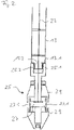
- the pressure medium hose 13 is connected to a cleaning head 25 at an opposite end 13.1. this is in 2 shown schematically.
- the length of the pressure medium hose 13 depends on the length of a hose filter to be cleaned.
- the end 13.1 of the pressure medium hose 13 has an external thread 13.2 which meshes with an internal thread 25.2 of a cover 25.1. This way he can Cleaning head 25 are screwed onto the end of the pressure medium hose 13 13.1.
- the screw connection is fixed but detachable and well suited for an operationally reliable connection.
- a rotor 27 is formed in the cleaning head 25, which has at least one cleaning bore 27.1, which is aligned essentially radially and directs a cleaning jet of the pressure medium in the direction of an inner wall of the bag filter.
- the drive shaft 23 is connected to the rotor 27 and drives the rotor 27 and thus the cleaning hole 27.1 to rotate when the drive device 15 is switched on.
- the rotor 27 is largely covered on the outside by a jacket 29 of the cleaning head 25, so that the rotating components of the cleaning head 25 are not exposed. This prevents physical contact between the rotor 27 and a support basket arranged in the bag filter for clamping the bag filter.
- a recess 30 is formed in the jacket 29, which is aligned with the cleaning hole 27.1 when both are aligned.
- the drive device 15 ⁇ is arranged in the cleaning head 25 ⁇ . This replaces there the drive device 15 in the control box 3.
- the pressure medium pipe 11 does not have to have a pipe extension 11.3 with the sealing device 11.4, at least this is then tightly closed by a closure (not shown).
- the drive device 15 ⁇ is integrated in the cleaning head 25 ⁇ .
- the cleaning head 25 ⁇ in 3 has below the rotor 27 ⁇ in a space 33 ⁇ enclosed by an end cap 31 ⁇ on the drive device 15 ⁇ , which is connected via the drive shaft 23 ⁇ to the rotor 27 ⁇ .
- the drive shaft 23 * does not have to, as in FIG 2 and 3 described and does not belong to the invention, can be flexible, but can also be rigid.
- An accumulator is used here as a voltage source 35 ⁇ .
- a controller 37 ⁇ is arranged with which the drive device 15 ⁇ can be controlled.
- the drive device 15 * is an electric motor.
- the controller 37 ⁇ is via a radio link with the Control device 19 connected so that the drive device 15 ⁇ from the outside can be served. Alternatively, wired connections between the controller 37 ⁇ and the drive device 15 ⁇ can be used.
Claims (8)
- Dispositif de nettoyage pour un filtre à manche suspendu dans un fond à filtre, avec une tête de nettoyage (25*), qui est reliée à une extrémité par un tuyau de moyen de pression (13) avec une source de moyen de pression et comporte un orifice de nettoyage (27.1*), qui peut être déporté en rotation autour d'un axe principal de la tête de nettoyage (25*) et à travers lequel sort un moyen de pression, sachant qu'un système d'entraînement (15*) est disposé dans la tête de nettoyage (25*), lequel déporte en rotation l'orifice de nettoyage (27.2*) et avec un dispositif de contrôle (19) pour piloter des paramètres de fonctionnement et le système d'entraînement (15*),
caractérisé en ce que
le système d'entraînement (15*) est disposé dans un compartiment (33*), qui forme une extrémité libre de la tête de nettoyage (25*) reliée au tuyau de moyen de pression (13) et introduite dans le filtre à manche suspendu et est fermée entourée par un capuchon (31*). - Dispositif de nettoyage selon la revendication 1,
caractérisé en ce que
la tête de nettoyage (25*) comporte un rotor (27*) dans lequel est constitué l'orifice de nettoyage (27.1*) - Dispositif de nettoyage selon la revendication 2,
caractérisé en ce que
le tuyau de moyen de pression (13) est couplé sur une extrémité opposée à la tête de nettoyage (25*) à un tuyau sous pression (11). - Dispositif de nettoyage selon la revendication 3,
caractérisé en ce qu'
un régulateur (37*) est disposé dans le compartiment (33*). - Dispositif de nettoyage selon la revendication 4,
caractérisé en ce que
le régulateur (37*) est relié au système de contrôle (19) par le biais d'une liaison radio. - Dispositif de nettoyage selon la revendication 4 ou 5,
caractérisé en ce que
le régulateur (37*) est relié à une alimentation de tension. - Dispositif de nettoyage selon la revendication 6,
caractérisé en ce que
l'alimentation de tension comprend un accumulateur sous la forme de source de tension (35*). - Dispositif de nettoyage selon l'une quelconque des revendications 3 à 7,
caractérisé en ce que
le tuyau sous pression (11) comporte une soupape de contrôle (11.2).
Priority Applications (4)
| Application Number | Priority Date | Filing Date | Title |
|---|---|---|---|
| EP18000949.0A EP3662985B1 (fr) | 2018-12-07 | 2018-12-07 | Dispositif de nettoyage pour filtre à manches |
| EP20000066.9A EP3689438B1 (fr) | 2018-12-07 | 2018-12-07 | Dispositif de nettoyage pour un filtre à manches |
| US16/221,929 US20200179861A1 (en) | 2018-12-07 | 2018-12-17 | Cleaning system for bag filters |
| ZA2019/07907A ZA201907907B (en) | 2018-12-07 | 2019-11-28 | Cleaning apparatus for bag filters |
Applications Claiming Priority (1)
| Application Number | Priority Date | Filing Date | Title |
|---|---|---|---|
| EP18000949.0A EP3662985B1 (fr) | 2018-12-07 | 2018-12-07 | Dispositif de nettoyage pour filtre à manches |
Related Child Applications (2)
| Application Number | Title | Priority Date | Filing Date |
|---|---|---|---|
| EP20000066.9A Division-Into EP3689438B1 (fr) | 2018-12-07 | 2018-12-07 | Dispositif de nettoyage pour un filtre à manches |
| EP20000066.9A Division EP3689438B1 (fr) | 2018-12-07 | 2018-12-07 | Dispositif de nettoyage pour un filtre à manches |
Publications (2)
| Publication Number | Publication Date |
|---|---|
| EP3662985A1 EP3662985A1 (fr) | 2020-06-10 |
| EP3662985B1 true EP3662985B1 (fr) | 2022-05-18 |
Family
ID=64664005
Family Applications (2)
| Application Number | Title | Priority Date | Filing Date |
|---|---|---|---|
| EP20000066.9A Active EP3689438B1 (fr) | 2018-12-07 | 2018-12-07 | Dispositif de nettoyage pour un filtre à manches |
| EP18000949.0A Active EP3662985B1 (fr) | 2018-12-07 | 2018-12-07 | Dispositif de nettoyage pour filtre à manches |
Family Applications Before (1)
| Application Number | Title | Priority Date | Filing Date |
|---|---|---|---|
| EP20000066.9A Active EP3689438B1 (fr) | 2018-12-07 | 2018-12-07 | Dispositif de nettoyage pour un filtre à manches |
Country Status (3)
| Country | Link |
|---|---|
| US (1) | US20200179861A1 (fr) |
| EP (2) | EP3689438B1 (fr) |
| ZA (1) | ZA201907907B (fr) |
Families Citing this family (1)
| Publication number | Priority date | Publication date | Assignee | Title |
|---|---|---|---|---|
| CN114226351B (zh) * | 2021-08-16 | 2024-01-30 | 重庆大学 | 一种复合材料干切加工复杂多工况自适应除尘装置 |
Family Cites Families (7)
| Publication number | Priority date | Publication date | Assignee | Title |
|---|---|---|---|---|
| JP4473401B2 (ja) * | 2000-03-17 | 2010-06-02 | 株式会社Ihi環境エンジニアリング | バグフィルターの濾布清掃用ノズル装置 |
| EP1543872B1 (fr) | 2003-12-10 | 2006-10-04 | Christian Reining | Dispositif de filtration avec un manche de filtration et un dispositif de nettoyage pour le manche de filtration |
| PT1932577E (pt) | 2006-11-15 | 2009-04-27 | Christian Reining | Dispositivo de limpeza com uma cabeça de limpeza e um método para limpar os filtros de mangueiras. |
| JP2010247138A (ja) * | 2009-04-16 | 2010-11-04 | Hirohito Ito | フィルタ清掃用ノズルシステム |
| EP2409788B1 (fr) | 2010-07-21 | 2015-12-02 | Christian Reining | Cloche d'aspiration pour un dispositif de nettoyage mobile, installation de nettoyage mobile dotée d'une telle cloche d'aspiration et procédé de nettoyage |
| DE202013009510U1 (de) * | 2013-06-01 | 2013-12-19 | Stephan Spanner | Düsenkopf und Reinigungsvorrichtung mit einem solchen Düsenkopf |
| WO2016006742A1 (fr) * | 2014-07-11 | 2016-01-14 | 이충중 | Dispositif pour réutiliser sac filtrant portatif |
-
2018
- 2018-12-07 EP EP20000066.9A patent/EP3689438B1/fr active Active
- 2018-12-07 EP EP18000949.0A patent/EP3662985B1/fr active Active
- 2018-12-17 US US16/221,929 patent/US20200179861A1/en not_active Abandoned
-
2019
- 2019-11-28 ZA ZA2019/07907A patent/ZA201907907B/en unknown
Also Published As
| Publication number | Publication date |
|---|---|
| EP3662985A1 (fr) | 2020-06-10 |
| EP3689438B1 (fr) | 2021-09-01 |
| EP3689438A1 (fr) | 2020-08-05 |
| ZA201907907B (en) | 2022-03-30 |
| US20200179861A1 (en) | 2020-06-11 |
Similar Documents
| Publication | Publication Date | Title |
|---|---|---|
| DE2626008C3 (de) | Luftreiniger | |
| EP2864050B1 (fr) | Dispositif et procédé pour séparer des impuretés magnétisables de fluides en écoulement | |
| DE2006685A1 (de) | Selbstreinigendes Filter | |
| DE10151864A1 (de) | Verfahren zum Betrieb eines Filters für Flüssigkeiten und System zur Durchführung des Verfahrens | |
| EP3621717B1 (fr) | Dispositif de filtration | |
| EP2468379A1 (fr) | Dispositif de filtre | |
| EP3662985B1 (fr) | Dispositif de nettoyage pour filtre à manches | |
| EP2756874A1 (fr) | Dispositif de filtre | |
| EP1706192B1 (fr) | Dispositif filtrant | |
| DE4002290A1 (de) | Rueckspuelbares filtergeraet | |
| EP1946812A1 (fr) | Filtre à rétrolavage | |
| EP2468380B1 (fr) | Dispositif de filtre | |
| DE102014219569B4 (de) | Wasserfiltereinrichtung mit rückspülbarem Wasserfilter mit Fließgeschwindigkeitsreduktion und Verfahren zum Rückspülen eines Wasserfilters | |
| EP3160711B1 (fr) | Système de filtre pour matière en fusion avec système de transport à vis de rétrolavage | |
| DE202006004529U1 (de) | Filtereinsatz mit Verschluss für zweite Filterkammer | |
| DE102009035895B4 (de) | Filteranordnung | |
| DE102014012032A1 (de) | Verfahren und Vorrichtung zum Filtrieren einer Flüssigkeit | |
| DE102010022928A1 (de) | Verfahren zur Reinigung einer Filterpatrone und Filterpatronen-Reinigungsvorrichtung sowie Abscheider mit einer solchen Einrichtung | |
| DE10245013A1 (de) | Filterzentrifuge | |
| EP1851468B1 (fr) | Module de soupape | |
| EP4115964B1 (fr) | Dispositif filtre | |
| DE3046388C2 (de) | Spaltfilter für Flüssigkeiten | |
| DE10126048A1 (de) | Vorrichtung zum Reinigen staubbeladener Rohgase | |
| DE19923130A1 (de) | Vorrichtung zur Trennung eines Phasengemisches | |
| AT359434B (de) | Fluessigkeits-fliehkraftreiniger |
Legal Events
| Date | Code | Title | Description |
|---|---|---|---|
| PUAI | Public reference made under article 153(3) epc to a published international application that has entered the european phase |
Free format text: ORIGINAL CODE: 0009012 |
|
| STAA | Information on the status of an ep patent application or granted ep patent |
Free format text: STATUS: THE APPLICATION HAS BEEN PUBLISHED |
|
| AK | Designated contracting states |
Kind code of ref document: A1 Designated state(s): AL AT BE BG CH CY CZ DE DK EE ES FI FR GB GR HR HU IE IS IT LI LT LU LV MC MK MT NL NO PL PT RO RS SE SI SK SM TR |
|
| AX | Request for extension of the european patent |
Extension state: BA ME |
|
| STAA | Information on the status of an ep patent application or granted ep patent |
Free format text: STATUS: REQUEST FOR EXAMINATION WAS MADE |
|
| 17P | Request for examination filed |
Effective date: 20201209 |
|
| RBV | Designated contracting states (corrected) |
Designated state(s): AL AT BE BG CH CY CZ DE DK EE ES FI FR GB GR HR HU IE IS IT LI LT LU LV MC MK MT NL NO PL PT RO RS SE SI SK SM TR |
|
| STAA | Information on the status of an ep patent application or granted ep patent |
Free format text: STATUS: EXAMINATION IS IN PROGRESS |
|
| 17Q | First examination report despatched |
Effective date: 20210303 |
|
| STAA | Information on the status of an ep patent application or granted ep patent |
Free format text: STATUS: EXAMINATION IS IN PROGRESS |
|
| GRAP | Despatch of communication of intention to grant a patent |
Free format text: ORIGINAL CODE: EPIDOSNIGR1 |
|
| STAA | Information on the status of an ep patent application or granted ep patent |
Free format text: STATUS: GRANT OF PATENT IS INTENDED |
|
| INTG | Intention to grant announced |
Effective date: 20211221 |
|
| GRAS | Grant fee paid |
Free format text: ORIGINAL CODE: EPIDOSNIGR3 |
|
| GRAA | (expected) grant |
Free format text: ORIGINAL CODE: 0009210 |
|
| STAA | Information on the status of an ep patent application or granted ep patent |
Free format text: STATUS: THE PATENT HAS BEEN GRANTED |
|
| AK | Designated contracting states |
Kind code of ref document: B1 Designated state(s): AL AT BE BG CH CY CZ DE DK EE ES FI FR GB GR HR HU IE IS IT LI LT LU LV MC MK MT NL NO PL PT RO RS SE SI SK SM TR |
|
| REG | Reference to a national code |
Ref country code: GB Ref legal event code: FG4D Free format text: NOT ENGLISH |
|
| REG | Reference to a national code |
Ref country code: CH Ref legal event code: EP |
|
| REG | Reference to a national code |
Ref country code: IE Ref legal event code: FG4D Free format text: LANGUAGE OF EP DOCUMENT: GERMAN |
|
| REG | Reference to a national code |
Ref country code: DE Ref legal event code: R096 Ref document number: 502018009688 Country of ref document: DE |
|
| REG | Reference to a national code |
Ref country code: AT Ref legal event code: REF Ref document number: 1492822 Country of ref document: AT Kind code of ref document: T Effective date: 20220615 |
|
| REG | Reference to a national code |
Ref country code: LT Ref legal event code: MG9D |
|
| REG | Reference to a national code |
Ref country code: NL Ref legal event code: MP Effective date: 20220518 |
|
| PG25 | Lapsed in a contracting state [announced via postgrant information from national office to epo] |
Ref country code: SE Free format text: LAPSE BECAUSE OF FAILURE TO SUBMIT A TRANSLATION OF THE DESCRIPTION OR TO PAY THE FEE WITHIN THE PRESCRIBED TIME-LIMIT Effective date: 20220518 Ref country code: PT Free format text: LAPSE BECAUSE OF FAILURE TO SUBMIT A TRANSLATION OF THE DESCRIPTION OR TO PAY THE FEE WITHIN THE PRESCRIBED TIME-LIMIT Effective date: 20220919 Ref country code: NO Free format text: LAPSE BECAUSE OF FAILURE TO SUBMIT A TRANSLATION OF THE DESCRIPTION OR TO PAY THE FEE WITHIN THE PRESCRIBED TIME-LIMIT Effective date: 20220818 Ref country code: NL Free format text: LAPSE BECAUSE OF FAILURE TO SUBMIT A TRANSLATION OF THE DESCRIPTION OR TO PAY THE FEE WITHIN THE PRESCRIBED TIME-LIMIT Effective date: 20220518 Ref country code: LT Free format text: LAPSE BECAUSE OF FAILURE TO SUBMIT A TRANSLATION OF THE DESCRIPTION OR TO PAY THE FEE WITHIN THE PRESCRIBED TIME-LIMIT Effective date: 20220518 Ref country code: HR Free format text: LAPSE BECAUSE OF FAILURE TO SUBMIT A TRANSLATION OF THE DESCRIPTION OR TO PAY THE FEE WITHIN THE PRESCRIBED TIME-LIMIT Effective date: 20220518 Ref country code: GR Free format text: LAPSE BECAUSE OF FAILURE TO SUBMIT A TRANSLATION OF THE DESCRIPTION OR TO PAY THE FEE WITHIN THE PRESCRIBED TIME-LIMIT Effective date: 20220819 Ref country code: FI Free format text: LAPSE BECAUSE OF FAILURE TO SUBMIT A TRANSLATION OF THE DESCRIPTION OR TO PAY THE FEE WITHIN THE PRESCRIBED TIME-LIMIT Effective date: 20220518 Ref country code: ES Free format text: LAPSE BECAUSE OF FAILURE TO SUBMIT A TRANSLATION OF THE DESCRIPTION OR TO PAY THE FEE WITHIN THE PRESCRIBED TIME-LIMIT Effective date: 20220518 Ref country code: BG Free format text: LAPSE BECAUSE OF FAILURE TO SUBMIT A TRANSLATION OF THE DESCRIPTION OR TO PAY THE FEE WITHIN THE PRESCRIBED TIME-LIMIT Effective date: 20220818 |
|
| PG25 | Lapsed in a contracting state [announced via postgrant information from national office to epo] |
Ref country code: RS Free format text: LAPSE BECAUSE OF FAILURE TO SUBMIT A TRANSLATION OF THE DESCRIPTION OR TO PAY THE FEE WITHIN THE PRESCRIBED TIME-LIMIT Effective date: 20220518 Ref country code: PL Free format text: LAPSE BECAUSE OF FAILURE TO SUBMIT A TRANSLATION OF THE DESCRIPTION OR TO PAY THE FEE WITHIN THE PRESCRIBED TIME-LIMIT Effective date: 20220518 Ref country code: LV Free format text: LAPSE BECAUSE OF FAILURE TO SUBMIT A TRANSLATION OF THE DESCRIPTION OR TO PAY THE FEE WITHIN THE PRESCRIBED TIME-LIMIT Effective date: 20220518 Ref country code: IS Free format text: LAPSE BECAUSE OF FAILURE TO SUBMIT A TRANSLATION OF THE DESCRIPTION OR TO PAY THE FEE WITHIN THE PRESCRIBED TIME-LIMIT Effective date: 20220918 |
|
| PG25 | Lapsed in a contracting state [announced via postgrant information from national office to epo] |
Ref country code: SM Free format text: LAPSE BECAUSE OF FAILURE TO SUBMIT A TRANSLATION OF THE DESCRIPTION OR TO PAY THE FEE WITHIN THE PRESCRIBED TIME-LIMIT Effective date: 20220518 Ref country code: SK Free format text: LAPSE BECAUSE OF FAILURE TO SUBMIT A TRANSLATION OF THE DESCRIPTION OR TO PAY THE FEE WITHIN THE PRESCRIBED TIME-LIMIT Effective date: 20220518 Ref country code: RO Free format text: LAPSE BECAUSE OF FAILURE TO SUBMIT A TRANSLATION OF THE DESCRIPTION OR TO PAY THE FEE WITHIN THE PRESCRIBED TIME-LIMIT Effective date: 20220518 Ref country code: EE Free format text: LAPSE BECAUSE OF FAILURE TO SUBMIT A TRANSLATION OF THE DESCRIPTION OR TO PAY THE FEE WITHIN THE PRESCRIBED TIME-LIMIT Effective date: 20220518 Ref country code: DK Free format text: LAPSE BECAUSE OF FAILURE TO SUBMIT A TRANSLATION OF THE DESCRIPTION OR TO PAY THE FEE WITHIN THE PRESCRIBED TIME-LIMIT Effective date: 20220518 Ref country code: CZ Free format text: LAPSE BECAUSE OF FAILURE TO SUBMIT A TRANSLATION OF THE DESCRIPTION OR TO PAY THE FEE WITHIN THE PRESCRIBED TIME-LIMIT Effective date: 20220518 |
|
| REG | Reference to a national code |
Ref country code: DE Ref legal event code: R097 Ref document number: 502018009688 Country of ref document: DE |
|
| PLBE | No opposition filed within time limit |
Free format text: ORIGINAL CODE: 0009261 |
|
| STAA | Information on the status of an ep patent application or granted ep patent |
Free format text: STATUS: NO OPPOSITION FILED WITHIN TIME LIMIT |
|
| PG25 | Lapsed in a contracting state [announced via postgrant information from national office to epo] |
Ref country code: AL Free format text: LAPSE BECAUSE OF FAILURE TO SUBMIT A TRANSLATION OF THE DESCRIPTION OR TO PAY THE FEE WITHIN THE PRESCRIBED TIME-LIMIT Effective date: 20220518 |
|
| 26N | No opposition filed |
Effective date: 20230221 |
|
| PG25 | Lapsed in a contracting state [announced via postgrant information from national office to epo] |
Ref country code: SI Free format text: LAPSE BECAUSE OF FAILURE TO SUBMIT A TRANSLATION OF THE DESCRIPTION OR TO PAY THE FEE WITHIN THE PRESCRIBED TIME-LIMIT Effective date: 20220518 |
|
| REG | Reference to a national code |
Ref country code: CH Ref legal event code: PL |
|
| REG | Reference to a national code |
Ref country code: BE Ref legal event code: MM Effective date: 20221231 |
|
| PG25 | Lapsed in a contracting state [announced via postgrant information from national office to epo] |
Ref country code: LU Free format text: LAPSE BECAUSE OF NON-PAYMENT OF DUE FEES Effective date: 20221207 |
|
| PG25 | Lapsed in a contracting state [announced via postgrant information from national office to epo] |
Ref country code: LI Free format text: LAPSE BECAUSE OF NON-PAYMENT OF DUE FEES Effective date: 20221231 Ref country code: IE Free format text: LAPSE BECAUSE OF NON-PAYMENT OF DUE FEES Effective date: 20221207 Ref country code: CH Free format text: LAPSE BECAUSE OF NON-PAYMENT OF DUE FEES Effective date: 20221231 |
|
| PG25 | Lapsed in a contracting state [announced via postgrant information from national office to epo] |
Ref country code: BE Free format text: LAPSE BECAUSE OF NON-PAYMENT OF DUE FEES Effective date: 20221231 |
|
| PGFP | Annual fee paid to national office [announced via postgrant information from national office to epo] |
Ref country code: GB Payment date: 20231228 Year of fee payment: 6 |
|
| PG25 | Lapsed in a contracting state [announced via postgrant information from national office to epo] |
Ref country code: IT Free format text: LAPSE BECAUSE OF FAILURE TO SUBMIT A TRANSLATION OF THE DESCRIPTION OR TO PAY THE FEE WITHIN THE PRESCRIBED TIME-LIMIT Effective date: 20220518 |
|
| PGFP | Annual fee paid to national office [announced via postgrant information from national office to epo] |
Ref country code: FR Payment date: 20231228 Year of fee payment: 6 Ref country code: AT Payment date: 20231227 Year of fee payment: 6 |
|
| PG25 | Lapsed in a contracting state [announced via postgrant information from national office to epo] |
Ref country code: HU Free format text: LAPSE BECAUSE OF FAILURE TO SUBMIT A TRANSLATION OF THE DESCRIPTION OR TO PAY THE FEE WITHIN THE PRESCRIBED TIME-LIMIT; INVALID AB INITIO Effective date: 20181207 |
|
| PG25 | Lapsed in a contracting state [announced via postgrant information from national office to epo] |
Ref country code: CY Free format text: LAPSE BECAUSE OF FAILURE TO SUBMIT A TRANSLATION OF THE DESCRIPTION OR TO PAY THE FEE WITHIN THE PRESCRIBED TIME-LIMIT Effective date: 20220511 |
|
| PGFP | Annual fee paid to national office [announced via postgrant information from national office to epo] |
Ref country code: DE Payment date: 20231220 Year of fee payment: 6 |