EP3662561B1 - Adapter für eine ladestation für telekommunikationsendgeräte - Google Patents
Adapter für eine ladestation für telekommunikationsendgeräte Download PDFInfo
- Publication number
- EP3662561B1 EP3662561B1 EP18769026.8A EP18769026A EP3662561B1 EP 3662561 B1 EP3662561 B1 EP 3662561B1 EP 18769026 A EP18769026 A EP 18769026A EP 3662561 B1 EP3662561 B1 EP 3662561B1
- Authority
- EP
- European Patent Office
- Prior art keywords
- charging station
- platform
- accordance
- adapter
- fixing block
- Prior art date
- Legal status (The legal status is an assumption and is not a legal conclusion. Google has not performed a legal analysis and makes no representation as to the accuracy of the status listed.)
- Active
Links
Images




Classifications
-
- H—ELECTRICITY
- H02—GENERATION; CONVERSION OR DISTRIBUTION OF ELECTRIC POWER
- H02J—ELECTRIC POWER NETWORKS; CIRCUIT ARRANGEMENTS OR SYSTEMS FOR SUPPLYING OR DISTRIBUTING ELECTRIC POWER; SYSTEMS FOR STORING ELECTRIC ENERGY
- H02J7/00—Circuit arrangements for charging or discharging batteries or for supplying loads from batteries
- H02J7/70—Circuit arrangements for charging or discharging batteries or for supplying loads from batteries characterised by the mechanical construction
- H02J7/731—Circuit arrangements for charging or discharging batteries or for supplying loads from batteries characterised by the mechanical construction specially adapted for holding portable devices containing batteries
-
- H—ELECTRICITY
- H02—GENERATION; CONVERSION OR DISTRIBUTION OF ELECTRIC POWER
- H02J—ELECTRIC POWER NETWORKS; CIRCUIT ARRANGEMENTS OR SYSTEMS FOR SUPPLYING OR DISTRIBUTING ELECTRIC POWER; SYSTEMS FOR STORING ELECTRIC ENERGY
- H02J7/00—Circuit arrangements for charging or discharging batteries or for supplying loads from batteries
- H02J7/50—Circuit arrangements for charging or discharging batteries or for supplying loads from batteries acting upon multiple batteries simultaneously or sequentially
-
- H—ELECTRICITY
- H02—GENERATION; CONVERSION OR DISTRIBUTION OF ELECTRIC POWER
- H02J—ELECTRIC POWER NETWORKS; CIRCUIT ARRANGEMENTS OR SYSTEMS FOR SUPPLYING OR DISTRIBUTING ELECTRIC POWER; SYSTEMS FOR STORING ELECTRIC ENERGY
- H02J7/00—Circuit arrangements for charging or discharging batteries or for supplying loads from batteries
- H02J7/70—Circuit arrangements for charging or discharging batteries or for supplying loads from batteries characterised by the mechanical construction
- H02J7/751—Circuit arrangements for charging or discharging batteries or for supplying loads from batteries characterised by the mechanical construction concerning the insertion or the connection of the batteries
-
- G—PHYSICS
- G04—HOROLOGY
- G04G—ELECTRONIC TIME-PIECES
- G04G19/00—Electric power supply circuits specially adapted for use in electronic time-pieces
-
- G—PHYSICS
- G06—COMPUTING OR CALCULATING; COUNTING
- G06F—ELECTRIC DIGITAL DATA PROCESSING
- G06F1/00—Details not covered by groups G06F3/00 - G06F13/00 and G06F21/00
- G06F1/16—Constructional details or arrangements
- G06F1/1613—Constructional details or arrangements for portable computers
- G06F1/1632—External expansion units, e.g. docking stations
Definitions
- the invention relates to a charging station for telecommunication devices and other small electronic devices such as clocks, with a platform having a plurality of webs arranged parallel to one another, below which supply cables and plug connections for connection to the associated charger can be laid, whereby to connect the telecommunication or small devices positioned on the platform at least one adapter is used with the supply cables or plug connections below the platform.
- Telecommunication terminals such as cell phones or tablet computers, as well as small devices such as electronic watches, are enjoying increasing popularity, so that several of these devices can be found in many households or offices. Every user knows the problem that their devices are often misplaced or that there is no suitable place to charge the device's batteries, often because a roommate or employee is charging his device. This also applies in the event that you are not at home or in the office, but in a place that you are not very familiar with, such as a hotel. Stations for receiving several such portable devices are already known, for example from the WO 2017/008768 or the WO 2014/198262 . Such devices are, however, limited in their manageability, especially since adapters are necessary to establish the connection between the device to be charged and the supply.
- the object of the present invention is to create a charging station for telecommunication devices and small electronic devices such as clocks, which is particularly suitable for accommodating several, even different, end devices and for their installation and removal and secure connection to the power supply.
- a preferred embodiment of the invention provides that an adapter can be inserted and fixed with its longitudinal axis transversely to the webs of a platform and a receptacle for a telecommunications or small device and one to be inserted between two webs of the platform and with the receptacle via a type of Has the extension arm formed connecting arm connected fixing block and wherein a corresponding to the receptacle, and the fixing block formed cover is provided, which is designed to be connected to the receptacle and the connecting arm via a latching.
- a large number of telecommunications and small devices can be arranged on or in the platform, all of which are connected to a charger, such as a USB charger.
- the connection represents such an adapter, which is arranged on the webs transversely to the webs and has a receptacle for a telecommunications or small device.
- a fixing block which can be inserted between two adjacent webs and which in turn is connected to the receptacle via a connecting arm is used to fix the adapter. This creates an adapter that can be used particularly flexibly and is easy to handle, is easy to assemble and can be dismantled again, and which is also characterized by high compatibility.
- a further advantageous embodiment of the invention provides that the receptacle, connecting arm and / or fixing block are designed as separate components to be connected to one another, so that cables between the receptacle and the block, in other words, between the top and bottom of the platform are very good install and have it dismantled again.
- Recording and Connecting arms can expediently be designed in one piece and are then connected to the fixing block as an assembly.
- the respective device can be used without any special effort and regardless of how many other devices are already installed.
- connecting arm and the fixing block are connected to one another via a latching connection.
- This latching connection is preferably designed such that the fixing block is pushed laterally into the connecting arm, that is to say transversely to its longitudinal axis - or vice versa.
- the fixing block has an inclination on its upper side, which is then transferred to the connecting arm and in particular to the receptacle.
- the receptacle is designed as a fastening for a fitness armband.
- a fitness armband is placed around a corresponding holder and then charged at the same time, with pockets being able to serve to accommodate the holder.
- the receptacle has two pockets, interrupted by a longitudinal slot, for receiving the fitness bracelet.
- the fixing block If the fixing block is positioned below the receptacle, a particularly large receptacle for a telecommunications or small electronic device is created.
- the fixing block assumes its position between the webs, but at the same time the receptacle is naturally dimensioned such that it or the adapter is held between the webs.
- the length and / or width of the receptacle are dimensioned larger than the clear distance between two webs of the platform, so that the fixing block disappears between the two webs, but at the same time the adapter is held thanks to its sufficiently large dimensions and thanks to the block also against rotation secured.
- Another advantageous embodiment of the invention provides that the distance between two adjacent webs is dimensioned to accommodate two telecommunications or small devices arranged one behind the other.
- This proposal is in connection with a technology in which it comes to the contactless charging of batteries.
- the charging station according to the invention offers a solution here in that two cell phones can be used one behind the other, for example in a correspondingly dimensioned free space between two webs.
- Another advantageous embodiment of the invention provides that a magnetic connection is provided between the platform and the housing into which the platform is to be inserted.
- the platform is used to accommodate the telecommunications and small devices and to establish the connection with chargers below the platform, which also forms the upper end of the housing. So that the connection between the housing and the platform is additionally stabilized, it is thought that a magnetic connection is provided between the platform and the housing into which the platform is to be inserted.
- the case is such that the inside of the housing has a collar for supporting the platform and that at least one magnet is provided between the collar and the upper edge of the housing. This means that the platform is flush with the upper edge of the housing on the one hand and on the other hand there is additional support thanks to the magnetic strips.
- the platform has at least one magnet each on the outside of its outer longitudinal webs.
- the invention is characterized in particular in that a charging station and an adapter for a charging station for telecommunications and small electronic devices are created, which are characterized by high functionality, easy assembly and disassembly and simple and safe handling.
- an adapter consisting of a receptacle, a fastening block and a connecting arm in the manner of a cantilever for connecting the receptacle and the fastening block is provided, which is to be positioned transversely to the webs and which is characterized by high compatibility, in particular because the receptacle corresponds to the respective telecommunications or small electronic device. Cables for connecting the top and bottom of the platform or the device to the charging station are effectively accommodated and integrated in the area of the receiving, connecting arm and / or fixing block so that they do not appear to the outside.
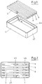
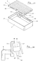
- a charging station 1 which is composed of a housing 27 and a platform 3.
- the housing 27 has a circumferential collar 44 which enables the platform 2 to be inserted into the housing 27.
- the platform 3 comprises several longitudinal webs, three of which are provided with the reference numerals 4, 5 and 6 by way of example.
- FIG. 2 a charging station 1 with the bushings 45, 46 etc. for the cables.
- the distance between the longitudinal webs 4 and 5 is larger than the distance between the other webs for the purpose of accommodating several telecommunication or small devices one behind the other with joint use of the relevant connection.
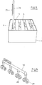
- FIG. 4 shows compensating elements 28, 29 etc. on an arm 30 prior to installation.
- Such a compensating element is used to bridge a plug connection. It often happens that such plugs do not assume the ideal fit, but rather slip slightly, especially inward, for which purpose such a compensating element 28, 29 is used.
- a housing 27 shows Figure 5 with two additional installations.
- One is represented by the tube 31 with a receptacle for a fastening means (not shown here) when assembling the charging station, formed from the platform and the housing 27.
- the other focus is on the bridge 33 on the bottom 32 of the housing 27.
- the bridge 33 has several holes , two of which are exemplarily provided with 36 and 37 and which serve to lead through or fix the cables and thus also to ensure that a certain sorting of the cables takes place inside the housing 27.
- Recesses 34, 35 are used for fastening means, not shown here.
- Such a bridge 33 then shows Figure 6 in plan view with the exemplary receptacles 34 and 35 for the fastening means, not shown here.
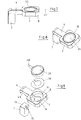
- FIG. 7 An adapter 2 which is not covered by the claimed invention is shown Figure 7 with the essential components receptacle 8, here for an electronic clock 23, fixing block 7 and connecting arm 9, so that such an adapter 2 can be inserted and fixed with its longitudinal axis 47 transversely to the webs of the platform.
- FIG. 9 it is then an exploded view for such an adapter 2.
- the block 7 has an inclination on its upper side 12, which the block 7 then so to speak specifies for the connecting arm and in particular for the receptacle 8.
- a recess for a cable is designated on the block side.
- Figure 9 the component consisting of receptacle 8 and connecting arm 9.
- the recesses 14 for the cables in the head plate 16 or the recess 8 can be clearly seen.
- 38 denotes a compensating ring and 23 denotes the electronic clock with its connection 48. It is easy to imagine with reference to FIG Figure 9 also how the latching connection between the fixing block 7 and the connecting arm 9 can be established in that both components correspond to one another on their upper side 12 and their lower side 49.
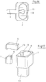
- FIG. 10 A variant for an adapter 2 shows Figure 10 , which in turn mainly consists of the components fixing block 7, connecting arm 9 and receptacle 8, for example in order to be able to accommodate Bluetooth headphones in receptacle 8 for the purpose of charging.
- Figure 13 Such a camera 40 as an example of a small device 24, connected to the receptacle 8 and thus to the adapter 2 in the form of an in Figure 13 indicated joint.
- Figure 14 again shows the adapter 2, here without a cover, whereupon below Figure 15 will have to be entered.
- FIG. 15 namely shows the cover 20 for the adapter 2.
- This cover 20 has latching means 21 on its upper side 22, with which the adapter 2 and the small device 24 in the form of the camera can be rotatably and pivotably connected to one another. At the same time, the adapter 2 naturally bridges the distance between the camera and the charging station.
- the cover for the housing of the camera 40 is also designated by 41.
- FIG. 16 A further variant which is not covered by the claimed invention is then shown Figure 16 and Figure 17 .
- the receptacle 8 in can be seen from above Figure 16 with the recess 13 for guiding the cable in the direction of or below the connecting arm 9.
- Figure 17 illustrates an adapter 2, in which the length and width of the receptacle 8 are dimensioned larger than the clear distance between two webs, which is expressed by the smaller dimensioning of the block 50 in relation to the receptacle 8.
- Figure 18 shows a cover 20 with the connecting arm 9 ′ and a fixing plate 51.
- Figure 19 shows the adapter 2 with fixing block 7, receptacle 8 and connecting arm 9, to which the in Figure 18 Lid shown can be put on.
- Two pockets 17, 18, which are separated from one another by a longitudinal slot 19 and whose function is shown in FIG Figure 20 is explained in more detail.
- Figure 20 shows Figure 20 an adapter 2 with two arms 42, 43 and a center piece 52 as a receptacle 8 for a fitness bracelet, not shown here, which then rests on top of the center piece 52 during storage or charging.
- FIG. 21 shows a charging station 1 with housing 27 and the platform 3 inserted in this housing 27.
- the housing 27 comprises a circumferential collar 44, the positioning of which is coordinated so that the platform 3 with the webs 4 etc. with the upper edge 63 of the housing 27 is flush.
- These magnetic strips 58, 59 on opposite inner sides of the housing 27 correspond to magnetic strips 60, 61 on opposite outer sides of the platform 3, more precisely said with the magnetic strips 60, 61 on the outside 64 of the outer longitudinal web 4 of the platform 3 (after a rotation of the platform 3 by 180 °).
- a positioning of magnetic strips on opposite flanks of housing 27 and platform 3 has proven to be particularly advantageous.
- the adapter 2 for receiving a bracelet, in particular a fitness bracelet with indicators for health and fitness as well as for recording activities, periods of rest, etc. or headphones, etc.
- the adapter 2 comprises, in addition to the cantilever arm 9, two wing-like arms 42 and 43, which are lie opposite and serve together to accommodate the device, not shown here.
- the middle piece or the receptacle is referred to, which in turn has a connection 65 on the bottom 67 of the Has recording. This is the connection to the charger, while the connections are provided with the reference numeral 66 on the upper side 68 of the receptacle 8. This is used to establish the connection to the device. It is therefore easy to recognize in Figure 22 the efficiency of the receptacle such as the securing of the device via the arms 42, 43 and the receptacle 8.
Landscapes
- Engineering & Computer Science (AREA)
- Power Engineering (AREA)
- Physics & Mathematics (AREA)
- General Physics & Mathematics (AREA)
- Charge And Discharge Circuits For Batteries Or The Like (AREA)
Description
- Die Erfindung betrifft eine Ladestation für Telekommunikationsgeräte und andere elektronische Kleingeräte wie Uhren, mit einer mehrere parallel zueinander angeordnete Stege aufweisenden Plattform, unterhalb welcher Versorgungskabel und Steckverbindungen zum Anschluss an das zugehörige Ladegerät verlegbar sind, wobei zur Verbindung der auf der Plattform positionierten Telekommunikations- oder Kleingeräte mit den Versorgungskabeln oder Steckverbindungen unterhalb der Plattform mindestens ein Adapter dient.
- Telekommunikationsendgeräte wie Mobiltelefone oder Tablet-Computer, auch Kleingeräte wie elektronische Uhren, erfreuen sich zunehmender Beliebtheit, sodass in vielen Haushalten oder Büros gleich mehrere dieser Geräte zu finden sind. Dabei kennt jeder Benutzer das Problem, dass man seine Geräte häufig verlegt oder keinen geeigneten Platz zum Aufladen der Akkus der Geräte findet, häufig auch weil ein Mitbewohner oder Mitarbeiter gerade sein Gerät auflädt. Dies gilt auch für den Fall, dass man sich nicht Zuhause oder im Büro, sondern an einem Ort befindet, mit dem man nicht gut vertraut ist, etwa in einem Hotel. Bereits bekannt sind Stationen zur Aufnahme auch mehrerer solcher tragbarer Geräte, etwa aus der
WO 2017/008768 oder derWO 2014/198262 . Solche Geräte sind in ihrer Handhabbarkeit allerdings eingeschränkt, zumal Adapter notwendig sind, um die Verbindung zwischen dem aufzuladenden Gerät und der Versorgung herzustellen. - Der vorliegenden Erfindung stellt sich die Aufgabe, eine Ladestation für Telekommunikationsgeräte und elektronische Kleingeräte wie Uhren zu schaffen, die zur Aufnahme mehrerer, auch unterschiedlicher Endgeräte und für deren Ein- und Ausbau sowie sicheren Anschluss an die Stromversorgung besonders geeignet ist.
- Diese Aufgabe wird erfindungsgemäß durch die Gegenstände der unabhängigen Ansprüche gelöst. Vorteilhafte Ausführungsformen sind Gegenstand der abhängigen Ansprüche.
- Eine bevorzugte Ausführungsform der Erfindung sieht vor, dass ein Adapter mit seiner Längsachse quer zu den Stegen einer Plattform einsetzbar und fixierbar ist und eine Aufnahme für ein Telekommunikations- oder Kleingerät und einen zwischen zwei Stegen der Plattform einzusetzenden und mit der Aufnahme über einen in Art eines Auslegers ausgebildeten Verbindungsarm verbundenen Fixierklotz aufweist und wobei ein korrespondierend zu der Aufnahme, und dem Fixierklotz ausgebildeter Deckel vorgesehen ist, welcher über eine Verrastung mit der Aufnahme und dem Verbindungsarm verbindbar ausgebildet ist.
- Auf bzw. in der Plattform können also eine Vielzahl von Telekommunikations- und Kleingeräten angeordnet werden, die alle mit einem Ladegerät, etwa einem USB-Ladegerät verbunden sind. Die Verbindung stellt dabei solch ein Adapter dar, der quer zu den Stegen auf diesen angeordnet wird und eine Aufnahme für ein Telekommunikations- oder Kleingerät aufweist. Zur Fixierung des Adapters dient ein zwischen zwei benachbarten Stegen einsetzbarer Fixierklotz, der wiederum mit der Aufnahme über einen Verbindungsarm verbunden ist. Damit ist ein besonders flexibel einsetzbarer und leicht handhabbarer, gut zu montierender und wieder zu demontierender Adapter geschaffen, der sich zudem durch hohe Kompatibilität ausweist.
- Eine weitere vorteilhafte Ausführungsform der Erfindung sieht dabei vor, dass Aufnahme, Verbindungsarm und/oder Fixierklotz als separate, miteinander zu verbindende Bauteile ausgebildet sind, sodass sich Kabel zwischen der Aufnahme und dem Klotz, anders formuliert, zwischen Ober- und Unterseite der Plattform sehr gut installieren und auch wieder demontieren lassen. Aufnahme und Verbindungsarm können zweckmäßigerweise einteilig ausgebildet sein und werden dann als Baugruppe mit dem Fixierklotz verbunden. Das jeweilige Gerät kann ohne besonderen Aufwand und unabhängig davon, wieviel andere Geräte bereits installiert sind, eingesetzt werden.
- Zusätzlich werden diese Funktionen erleichtert, indem der Verbindungsarm und der Fixierklotz über eine Rastverbindung miteinander verbunden sind. Vorzugsweise ist diese Rastverbindung so ausgebildet, dass der Fixierklotz seitlich in den Verbindungsarm, also quer zu dessen Längsachse, eingeschoben wird - oder umgekehrt.
- Als zweckmäßig kann es sich erweisen, das Telekommunikations- oder Kleingerät, etwa eine elektronische Uhr, geneigt in die Plattform bzw. den Adapter einzusetzen, um beispielsweise diese Geräte während des Ladevorgangs besser bedienen zu können. In diesem Zusammenhang reicht es dann aus, wenn der Fixierklotz an seiner Oberseite eine Neigung aufweist, die sich dann auf den Verbindungsarm und insbesondere die Aufnahme überträgt.
- Die leichte Installation solch eines Adapters wurde bereits angesprochen. Damit das Kabel auch in geeigneter Form "verschwindet", empfiehlt es sich, wenn die Aufnahme, der Verbindungsarm und/oder der Fixierklotz Ausnehmungen zur Durchführung eines Kabels aufweisen und zwar bevorzugt an ihren Innenseiten.
- Dass die Aufnahme als Befestigung für ein Fitness-Armband ausgebildet ist, stellt eine bevorzugte Applikation dar. Solch ein elektronisches Fitness-Armband wird um eine entsprechende Halterung gelegt und dann gleichzeitig aufgeladen, wobei Taschen zur Aufnahme der Halterung dienen können. Dazu weist die Aufnahme zwei durch einen Längsschlitz unterbrochene Taschen zur Aufnahme des Fitness-Armbandes auf.
- Wenn der Fixierklotz unterhalb der Aufnahme positioniert ist, entsteht eine besonders große Aufnahme für ein Telekommunikations- oder ein elektronisches Kleingerät. Dabei nimmt der Fixierklotz seine Position zwischen den Stegen ein, gleichzeitig ist jedoch die Aufnahme naturgemäß so dimensioniert, dass sie bzw. der Adapter zwischen den Stegen gehalten ist.
- Anders formuliert, Länge und/oder Breite der Aufnahme sind größer dimensioniert als der lichte Abstand zwischen zwei Stegen der Plattform, sodass der Fixierklotz zwischen den beiden Stegen verschwindet, gleichzeitig ist der Adapter aber dank seiner ausreichend großen Dimensionierung gehalten und dank des Klotzes auch gegen Verdrehung gesichert.
- Eine zusätzliche Sicherung gegen Verschiebung der Adapter ist realisiert, wenn der Fixierklotz über mindestens ein Befestigungsmittel mit dem Gehäuseboden der Ladestation verbunden ist. Gedacht ist dabei etwa an eine Verschraubung. Aufgrund der Kompaktheit des Fixierklotzes sind hier stabile Verbindungen leicht realisierbar.
- Eine weitere vorteilhafte Ausführungsform der Erfindung sieht vor, dass der Abstand zwischen zwei benachbarten Stegen zur Aufnahme zweier hintereinander angeordneter Telekommunikations- oder Kleingeräte bemessen ist. Dieser Vorschlag steht in Verbindung mit einer Technologie, bei der es zur berührungslosen Aufladung von Akkus kommt. Hier bietet die erfindungsgemäße Ladestation eine Lösung, indem zwei Mobiltelefone beispielsweise in einem entsprechend dimensionierten Freiraum zwischen zwei Stegen hintereinander eingesetzt werden können.
- Um handelsübliche Geräte in diesem Sinne in dem Freiraum zwischen den Stegen unterbringen zu können, ist es sinnvoll, wenn die Stege einen lichten Abstand von 18 mm aufweisen.
- Eine weitere vorteilhafte Ausführungsform der Erfindung sieht vor, dass zwischen der Plattform und dem Gehäuse, in das die Plattform einzusetzen ist, eine Magnetverbindung vorgesehen ist. Die Plattform dient dabei zur Aufnahme der Telekommunikations- und Kleingeräte und zur Herstellung der Verbindung mit Ladegeräten unterhalb der Plattform, die zugleich den oberen Abschluss des Gehäuses bildet. Damit die Verbindung zwischen dem Gehäuse und der Plattform zusätzlich stabilisiert ist, ist daran gedacht, dass zwischen der Plattform und dem Gehäuse, in das die Plattform einzusetzen ist, eine Magnetverbindung vorgesehen ist.
- Konkret verhält es sich so, dass das Gehäuse an seiner Innenseite einen Kragen zur Auflage der Plattform aufweist und dass zwischen dem Kragen und der Oberkante des Gehäuses mindestens ein Magnet vorgesehen ist. Damit schließt die Plattform einerseits bündig mit der Oberkante des Gehäuses ab und andererseits ist zusätzlicher Halt dank der Magnetleisten gegeben.
- Besonders zweckmäßig sind diese Magnetleisten untergebracht, indem die Plattform an der Außenseite ihrer äußeren Längsstege mindestens jeweils einen Magneten aufweist. Beim Einsetzen der Plattform in das Gehäuse findet sich die Magnetverbindung damit quasi von selbst.
- Die Erfindung zeichnet sich insbesondere dadurch aus, dass eine Ladestation und ein Adapter für eine Ladestation für Telekommunikations- und elektronische Kleingeräte geschaffen sind, die sich durch hohe Funktionalität, leichte Montage und Demontage und einfache und sichere Handhabung auszeichnen. Dazu ist ein aus einer Aufnahme, einem Befestigungsklotz und einem Verbindungsarm in Art eines Auslegers zur Verbindung von Aufnahme und Befestigungsklotz bestehender Adapter vorgesehen, der quer zu den Stegen zu positionieren ist und der sich durch hohe Kompatibilität auszeichnet, indem insbesondere die Aufnahme dem jeweiligen Telekommunikations- oder elektronischen Kleingerät anzupassen ist. Kabel zur Verbindung der Ober- und Unterseite der Plattform bzw. des Gerätes mit der Ladestation werden auf effektive Weise so im Bereich von Aufnahme-, Verbindungsarm und/oder Fixierklotz untergebracht und integriert, dass sie nicht nach außen in Erscheinung treten.
- Weitere Einzelheiten und Vorteile des Erfindungsgegenstandes ergeben sich aus der nachfolgenden Beschreibung und der zugehörigen Zeichnungen.
- Figur 1
- eine Ladestation in Explosionsdarstellung,
- Figur 2
- eine Ladestation von oben,
- Figur 3
- eine Ladestation mit eingesetzten Telekommunikationsgeräten,
- Figur 4
- Ausgleichselemente,
- Figur 5
- das Gehäuse einer Ladestation mit Brücke,
- Figur 6
- eine Brücke,
- Figur 7
- einen Adapter in Seitenansicht,
- Figur 8
- einen Adapter in perspektivischer Ansicht,
- Figur 9
- einen Adapter in Explosionsdarstellung,
- Figur 10
- einen anderen Adapter in Seitenansicht,
- Figur 11
- diesen Adapter in Draufsicht,
- Figur 12
- diesen Adapter in Explosionsdarstellung,
- Figur 13
- eine weitere Variante eines Adapters in Seitenansicht,
- Figur 14
- dieser Adapter in perspektivischer Ansicht,
- Figur 15
- dieser Adapter in Explosionsdarstellung,
- Figur 16
- eine weitere Adaptervariante in Draufsicht,
- Figur 17
- dieser Adapter in Explosionsdarstellung,
- Figur 18
- einen Deckel,
- Figur 19
- einen Adapter ohne Deckel,
- Figur 20
- einen Adapter für ein Fitness-Armband,
- Figur 21
- eine ergänzende Darstellung zu
Figur 1 und - Figur 22
- eine Variante zu
Figur 20 . - In
Figur 1 ist eine Ladestation 1 gezeigt, die sich aus einem Gehäuse 27 und einer Plattform 3 zusammensetzt. Dazu weist das Gehäuse 27 einen umlaufenden Kragen 44 auf, der ein Einsetzen der Plattform 2 in das Gehäuse 27 ermöglicht. Die Plattform 3 umfasst mehrere Längsstege, von denen drei beispielhaft mit den Bezugszeichen 4, 5 und 6 versehen sind. - Von oben zeigt
Figur 2 eine Ladestation 1 mit den Durchführungen 45, 46 etc. für die Kabel. Der Abstand zwischen den Längsstegen 4 und 5 ist dabei größer bemessen als der Abstand zwischen den übrigen Stegen zwecks Unterbringung mehrerer Telekommunikations- oder Kleingeräte hintereinander unter gemeinsamer Ausnutzung des betreffenden Anschlusses. - Illustriert ist das in
Figur 3 mit den beiden eingesetzten Telekommunikationsgeräten 25, 26 in Form von Mobiltelefonen in dem Freiraum zwischen den beiden Längsstegen 4 und 5. Die beiden Telekommunikationsgeräte 25 und 26 teilen sich dabei gewissermaßen den Anschluss an die Aufladestation. -
Figur 4 zeigt Ausgleichselemente 28, 29 etc. an einem Arm 30 vor der Installation. Ein solches Ausgleichselement kommt zum Einsatz zur Überbrückung eines Steckeranschlusses. Häufig kommt es dazu, dass solche Stecker nicht den Idealsitz einnehmen, sondern geringfügig verrutschen, vor allem nach innen, wozu dann ein solches Ausgleichselement 28, 29 zum Einsatz kommt. - Ein Gehäuse 27 zeigt
Figur 5 mit zwei zusätzlichen Installationen. Eine wird abgebildet durch das Röhrchen 31 mit einer Aufnahme für ein hier nicht dargestelltes Befestigungsmittel beim Zusammenbau der Ladestation, gebildet aus Plattform und Gehäuse 27. Das andere Augenmerk gilt der Brücke 33 auf dem Boden 32 des Gehäuses 27. Die Brücke 33 weist mehrere Löcher auf, von denen zwei beispielhaft mit 36 und 37 versehen sind und die zur Durchführung bzw. Fixierung der Kabel und damit auch dazu dienen, dass eine gewisse Sortierung der Kabel im Inneren des Gehäuses 27 stattfindet. Aufnahmen 34, 35 dienen für hier nicht dargestellte Befestigungsmittel. - Solch eine Brücke 33 zeigt dann
Figur 6 in Draufsicht mit den beispielhaften Aufnahmen 34 und 35 für die hier nicht dargestellten Befestigungsmittel. - Einen Adapter 2 der nicht von der beanspruchten Erfindung erfasst wird, zeigt
Figur 7 mit den wesentlichen Bauteilen Aufnahme 8, hier für eine elektronische Uhr 23, Fixierklotz 7 und Verbindungsarm 9, sodass ein solcher Adapter 2 mit seiner Längsachse 47 quer zu den Stegen der Plattform eingesetzt und fixiert werden kann. - Dies verdeutlicht
Figur 8 mit einer geneigten Baugruppe aus Aufnahme 8 und Verbindungsarm 9. - Bei
Figur 9 handelt es sich dann um eine Explosionsdarstellung für solch einen Adapter 2. Erkennbar ist, dass der Klotz 7 an seiner Oberseite 12 eine Neigung aufweist, welche der Klotz 7 dann gewissermaßen für den Verbindungsarm und im Speziellen für die Aufnahme 8 vorgibt. Mit 15 ist eine Ausnehmung für ein Kabel klotzseitig bezeichnet. Dazu zeigtFigur 9 das aus Aufnahme 8 und Verbindungsarm 9 bestehende Bauteil. Gut zu erkennen sind die Ausnehmungen 14 für die Kabel in der Kopfplatte 16 bzw. der Ausnehmung 8. Mit 38 ist ein Ausgleichsring bezeichnet und mit 23 schließlich die elektronische Uhr mit ihrem Anschluss 48. Gut vorstellbar ist anhand vonFigur 9 auch, wie die Rastverbindung zwischen dem Fixierklotz 7 und dem Verbindungsarm 9 hergestellt werden kann, indem beide Bauteile an ihrer Oberseite 12 bzw. ihrer Unterseite 49 miteinander korrespondieren. - Eine Variante für einen Adapter 2 zeigt
Figur 10 , der wiederum maßgeblich aus den Bauteilen Fixierklotz 7, Verbindungsarm 9 und Aufnahme 8 besteht, etwa um Bluetooth-Kopfhörer in der Aufnahme 8 zwecks Aufladung unterbringen zu können. - Erkennbar ist dies in
Figur 11 mit der Ausnehmung 13 in der Aufnahme 8 zur Aufnahme von Versorgungskabeln. - Dazu veranschaulicht
Figur 12 , dass eine Art Deckel 20 auf den Adapter 2 im Bereich der Aufnahme 8 aufgesetzt wird, die beiden Teile 9, 9' des Verbindungsarms miteinander korrespondieren. - Um die Anwendung im Zusammenhang mit einer Kamera geht es in den Darstellungen gemäß
Figur 13 bis 15 . Zunächst zeigtFigur 13 solch eine Kamera 40 als Beispiel für ein Kleingerät 24, mit der Aufnahme 8 und so mit dem Adapter 2 verbunden in Form eines inFigur 13 angedeuteten Gelenkes. -
Figur 14 zeigt wiederum den Adapter 2, hier ohne einen Deckel, worauf unterFigur 15 noch einzugehen sein wird. - Diese
Figur 15 zeigt nämlich den Deckel 20 für den Adapter 2. Dieser Deckel 20 verfügt an seiner Oberseite 22 über Rastmittel 21, mit denen der Adapter 2 und das Kleingerät 24 in Form der Kamera dreh- und schwenkbar miteinander verbunden werden können. Gleichzeitig überbrückt der Adapter 2 naturgemäß den Abstand zwischen Kamera und Ladestation. Mit 41 ist noch der Deckel für das Gehäuse der Kamera 40 bezeichnet. - Eine weitere Variante die nicht von der beanspruchten Erfindung erfasst wird, zeigen dann
Figur 16 und Figur 17 . Von oben erkennbar ist die Aufnahme 8 inFigur 16 mit der Ausnehmung 13 zur Führung des Kabels in Richtung bzw. unterhalb des Verbindungsarms 9. -
Figur 17 veranschaulicht einen Adapter 2, bei dem Länge und Breite der Aufnahme 8 größer dimensioniert sind als der lichte Abstand zwischen zwei Stegen, was zum Ausdruck kommt durch die kleinere Dimensionierung des Klotzes 50 in Relation zu der Aufnahme 8. -
Figur 18 zeigt einen Deckel 20 mit dem Verbindungsarm 9' und einer Fixierplatte 51. -
Figur 19 zeigt dann den Adapter 2 mit Fixierklotz 7, Aufnahme 8 und Verbindungsarm 9, auf den der inFigur 18 gezeigte Deckel aufgesetzt werden kann. Als Aufnahme 8 dienen hier zwei Taschen 17, 18, die durch einen Längsschlitz 19 voneinander getrennt sind und deren Funktion inFigur 20 näher erläutert wird. - So zeigt
Figur 20 einen Adapter 2 mit zwei Armen 42, 43 und einem Mittelstück 52 als Aufnahme 8 für ein hier nicht dargestelltes Fitness-Armband, das dann während der Unterbringung bzw. Aufladung oben auf dem Mittelstück 52 aufliegt. -
Figur 21 zeigt eine Ladestation 1 mit Gehäuse 27 und der in dieses Gehäuse 27 eingesetzten Plattform 3. Das Gehäuse 27 umfasst einen umlaufenden Kragen 44, der in seiner Positionierung so abgestimmt ist, dass die Plattform 3 mit den Stegen 4 etc. mit der Oberkante 63 des Gehäuses 27 bündig abschließt. Zwischen dem Kragen 44 und der Oberkante 63 des Gehäuses 27 befinden sich an dessen Innenseite 62 zwei Magnetleisten 58, 59. Diese Magnetleisten 58, 59 an gegenüber liegenden Innenseiten des Gehäuses 27 korrespondieren mit Magnetleisten 60, 61 an gegenüber liegenden Außenseiten der Plattform 3, genauer gesagt mit den Magnetleisten 60, 61 an der Außenseite 64 des äußeren Längsstegs 4 der Plattform 3 (nach einer Drehung der Plattform 3 um 180°). Dabei erweist sich eine Positionierung von Magnetleisten an gegenüberliegenden Flanken von Gehäuse 27 und Plattform 3 als besonders vorteilhaft. - Schließlich zeigt
Figur 22 einen Adapter 2 zur Aufnahme eines Armbandes, insbesondere eines Fitnessarmbandes mit Anzeigen zur Gesundheit und Fitness sowie zur Aufzeichnung von Aktivitäten, Ruhephasen etc. oder eines Kopfhörers etc. Dazu umfasst der Adapter 2 neben dem Auslegerarm 9 über zwei flügelartige Arme 42 und 43, die sich gegenüber liegen und gemeinsam zur Aufnahme des hier nicht dargestellten Gerätes dienen. Mit 52 bzw. 8 ist das Mittelstück bzw. die Aufnahme bezeichnet, die ihrerseits einen Anschluss 65 an der Unterseite 67 der Aufnahme aufweist. Dabei handelt es sich um die Verbindung zum Ladegerät, während an der Oberseite 68 der Aufnahme 8 die Anschlüsse mit dem Bezugszeichen 66 versehen sind. Über diese wird die Verbindung zu dem Gerät hergestellt. Gut zu erkennen ist mithin inFigur 22 die Effizienz der Aufnahme wie die Sicherung des Gerätes über die Arme 42, 43 und die Aufnahme 8.
Claims (15)
- Ladestation (1) für Telekommunikationsgeräte und andere elektronische Kleingeräte wie Uhren, mit einer mehrere parallel zueinander angeordnete Stege (4 - 6) aufweisenden Plattform (3), unterhalb welcher Versorgungskabel und Steckverbindungen zum Anschluss an das zugehörige Ladegerät verlegbar sind, wobei zur Verbindung der auf der Plattform (3) positionierten Telekommunikations- oder Kleingeräte mit den Versorgungskabeln oder Steckverbindungen unterhalb der Plattform (3) mindestens ein Adapter (2) dient,
wobei der Adapter (3) mit seiner Längsachse (47) quer zu den Stegen (4,5) der Plattform (3) einsetzbar und fixierbar ist und eine Aufnahme (8) für ein Telekommunikations- oder Kleingerät und einen zwischen zwei Stegen (4, 5) der Plattform (3) einzusetzenden und mit der Aufnahme (8) über einen in Art eines Auslegers ausgebildeten Verbindungsarm (9) verbundenen Fixierklotz (7) aufweist und wobei der Adapter weiterhin dadurch gekennzeichnet ist, dass ein korrespondierend zu der Aufnahme (8), und dem Fixierklotz (7) ausgebildeter Deckel (20) vorgesehen ist, welcher über eine Verrastung mit der Aufnahme (8) und dem Verbindungsarm (9) verbindbar ausgebildet ist. - Ladestation nach Anspruch 1,
dadurch gekennzeichnet,
dass Aufnahme (8), Verbindungsarm (9) und/oder Fixierklotz (7) als separate, miteinander zu verbindende Bauteile ausgebildet sind. - Ladestation nach Anspruch 1,
dadurch gekennzeichnet,
dass der Verbindungsarm (9) und der Fixierklotz (7) über eine Rastverbindung miteinander verbunden sind. - Ladestation nach Anspruch 1,
dadurch gekennzeichnet,
dass der Fixierklotz (7) an seiner Oberseite (12) eine Neigung aufweist. - Ladestation nach Anspruch 1,
dadurch gekennzeichnet,
dass die Aufnahme (8), der Verbindungsarm (9) und/oder der Fixierklotz (7) Ausnehmungen (13 - 15) zur Durchführung eines Kabels aufweisen. - Ladestation nach Anspruch 1,
dadurch gekennzeichnet,
dass die Aufnahme (8) als Befestigung für ein Fitness-Armband ausgebildet ist. - Ladestation nach Anspruch 1,
dadurch gekennzeichnet,
dass der Adapter (2), insbesondere der Deckel (20) an seiner Oberseite (22) Rastmittel (21) zur Verbindung des Adapters (2) mit einem Gelenk aufweist. - Ladestation nach Anspruch 1,
dadurch gekennzeichnet,
dass der Fixierklotz (7) unterhalb der Aufnahme (8) positioniert ist. - Ladestation nach Anspruch 8,
dadurch gekennzeichnet,
dass Länge und/oder Breite der Aufnahme (8) größer dimensioniert sind als der lichte Abstand zwischen zwei Stegen (4, 5) der Plattform (3). - Ladestation nach Anspruch 1,
dadurch gekennzeichnet,
dass der Fixierklotz (7) über mindestens ein Befestigungsmittel mit dem Gehäuseboden (32) der Ladestation (1) verbunden ist. - Ladestation nach Anspruch 1,
dadurch gekennzeichnet,
dass der Abstand zwischen zwei benachbarten Stegen (4, 5) zur Aufnahme zweier hintereinander angeordneter Telekommunikations- oder Kleingeräte (23, 24) bemessen ist. - Ladestation nach Anspruch 11,
dadurch gekennzeichnet,
dass die Stege (4, 5) einen lichten Abstand von 18 mm aufweisen. - Ladestation nach Anspruch 1,
dadurch gekennzeichnet,
dass zwischen der Plattform (3) und dem Gehäuse (27), in das die Plattform (3) einzusetzen ist, eine Magnetverbindung (58 - 61) vorgesehen ist. - Ladestation nach Anspruch 13,
dadurch gekennzeichnet,
dass das Gehäuse (27) an seiner Innenseite (62) einen Kragen (44) zur Auflage der Plattform (3) aufweist und dass zwischen dem Kragen (44) und der Oberkante (63) des Gehäuses (27) mindestens ein Magnet (58, 59) vorgesehen ist. - Ladestation nach Anspruch 13,
dadurch gekennzeichnet,
dass die Plattform (3) an der Außenseite (64) ihrer äußeren Längsstege (4) mindestens jeweils einen Magneten (60, 61) aufweist.
Applications Claiming Priority (3)
| Application Number | Priority Date | Filing Date | Title |
|---|---|---|---|
| DE102017117730 | 2017-08-04 | ||
| DE102017122691.5A DE102017122691A1 (de) | 2017-08-04 | 2017-09-29 | Adapter für eine Ladestation für Telekommunikationsendgeräte |
| PCT/DE2018/100685 WO2019024962A1 (de) | 2017-08-04 | 2018-08-03 | Adapter für eine ladestation für telekommunikationsendgeräte |
Publications (2)
| Publication Number | Publication Date |
|---|---|
| EP3662561A1 EP3662561A1 (de) | 2020-06-10 |
| EP3662561B1 true EP3662561B1 (de) | 2021-05-05 |
Family
ID=65020155
Family Applications (1)
| Application Number | Title | Priority Date | Filing Date |
|---|---|---|---|
| EP18769026.8A Active EP3662561B1 (de) | 2017-08-04 | 2018-08-03 | Adapter für eine ladestation für telekommunikationsendgeräte |
Country Status (5)
| Country | Link |
|---|---|
| US (1) | US11398737B2 (de) |
| EP (1) | EP3662561B1 (de) |
| AU (1) | AU2018310508A1 (de) |
| DE (1) | DE102017122691A1 (de) |
| WO (1) | WO2019024962A1 (de) |
Families Citing this family (3)
| Publication number | Priority date | Publication date | Assignee | Title |
|---|---|---|---|---|
| US11239668B2 (en) * | 2018-09-21 | 2022-02-01 | Google Llc | Charger case for wearable electronics |
| US11862133B2 (en) * | 2021-10-11 | 2024-01-02 | Phillip David Garrison | Guitar modulator stand |
| USD1101681S1 (en) * | 2023-02-23 | 2025-11-11 | Rga Prosumer's Choice Llc | Modular charging station |
Family Cites Families (8)
| Publication number | Priority date | Publication date | Assignee | Title |
|---|---|---|---|---|
| US9124308B2 (en) * | 2009-05-12 | 2015-09-01 | Kimball International, Inc. | Furniture with wireless power |
| FR2948831B1 (fr) * | 2009-07-31 | 2022-01-28 | Jerome Gilbert | Systeme universel pour recharger au moins un appareil portable |
| US20130113420A1 (en) | 2012-10-02 | 2013-05-09 | John L. Majoris, JR. | Universal Station for Organizing and Charging Multiple Electronic Devices |
| DE102013009880A1 (de) | 2013-06-13 | 2014-12-18 | Klemens Dittrich | Ladestation für Telekommunikationsendgeräte |
| DE202013008702U1 (de) | 2013-09-25 | 2013-12-19 | Horst-Peter Heimes | Uhrständer mit Ladehalterung insbesondere für Smartwatch Pebble und herstellerseitige Ladevorrichtung sowohl zum Laden als auch zum Aufstellen der Uhr. |
| US9681759B2 (en) * | 2014-09-03 | 2017-06-20 | Apple Inc. | Table display system |
| CN105001352B (zh) | 2015-07-14 | 2017-04-26 | 青岛海大海洋生物医药销售有限公司 | 一种β‑1,3/1,6‑葡聚糖及其制备方法和在制备免疫增强和抗肿瘤的药物和功能性食品中的应用 |
| DE202015103714U1 (de) * | 2015-07-15 | 2015-09-07 | Klemens Dittrich | Ladestation für Telekommunikationsgeräte und elektronische Uhren |
-
2017
- 2017-09-29 DE DE102017122691.5A patent/DE102017122691A1/de not_active Withdrawn
-
2018
- 2018-08-03 US US16/636,362 patent/US11398737B2/en active Active
- 2018-08-03 AU AU2018310508A patent/AU2018310508A1/en not_active Abandoned
- 2018-08-03 WO PCT/DE2018/100685 patent/WO2019024962A1/de not_active Ceased
- 2018-08-03 EP EP18769026.8A patent/EP3662561B1/de active Active
Also Published As
| Publication number | Publication date |
|---|---|
| WO2019024962A1 (de) | 2019-02-07 |
| US20200244083A1 (en) | 2020-07-30 |
| EP3662561A1 (de) | 2020-06-10 |
| AU2018310508A1 (en) | 2020-03-19 |
| US11398737B2 (en) | 2022-07-26 |
| DE102017122691A1 (de) | 2019-02-07 |
Similar Documents
| Publication | Publication Date | Title |
|---|---|---|
| DE19620834C1 (de) | Einrichtung für Schnurlostelefone | |
| EP3662561B1 (de) | Adapter für eine ladestation für telekommunikationsendgeräte | |
| DE202016101967U1 (de) | Ladestation für Telekommunikationsgeräte und elektronische Uhren | |
| DE3024244C2 (de) | ||
| DE3014755A1 (de) | Aus einzelelementen zusammensteckbarer block fuer elektrische steckverbindungen | |
| DE4447144A1 (de) | Trägersystem für Datenübertragungsleitungen oder dergleichen | |
| EP3008881B1 (de) | Ladestation für telekommunikationsendgeräte | |
| EP3823110A1 (de) | Kontaktträger für elektrische steckverbinder und steckverbinder hierfür | |
| EP2701253A2 (de) | Kabelhalter-Anordnung | |
| DE69507450T2 (de) | Modulare elektrische Reihenklemmenanordnung | |
| DE102012100323A1 (de) | Eine Aufnahmevorrichtung für Werkzeugeinsätze | |
| EP0993171A2 (de) | Aufnahmegehäuse einer Türstation einer Türsprechanlage | |
| DE2518832C3 (de) | Kontaktsegment für Trenn- und Anschlußleisten | |
| DE1933201A1 (de) | Vorrichtung zum stromuebertragenden Verbinden von elektrischen Leitungen | |
| EP3724964A1 (de) | Ladestation für telekommunikationsgeräte, insbesondere für kabellose ladegeräte | |
| DE29910180U1 (de) | Betätigungswerkzeug | |
| EP2989668B1 (de) | Batterievorrichtung und maschine | |
| EP2645501B1 (de) | Systemmodul für die Gebäude-Elektroinstallationstechnik und Türkommunikationstechnik | |
| DE3237698C2 (de) | ||
| DE4013970C2 (de) | Sockelkörper | |
| DE8533097U1 (de) | Stromversorgungsgerät, insbesondere für Lehrzwecke | |
| EP3651281B1 (de) | Verbindungsanordnung zur modularen verbindung von gehäusen | |
| DE29908950U1 (de) | Telekommunikationseinrichtung für Sprach- und/oder Datenübertragung | |
| DE102012008996A1 (de) | Elektrische Kupplungsvorrichtung für ein optoelektronisches Bauelement | |
| EP3051781A1 (de) | Haltevorrichtung |
Legal Events
| Date | Code | Title | Description |
|---|---|---|---|
| STAA | Information on the status of an ep patent application or granted ep patent |
Free format text: STATUS: UNKNOWN |
|
| STAA | Information on the status of an ep patent application or granted ep patent |
Free format text: STATUS: THE INTERNATIONAL PUBLICATION HAS BEEN MADE |
|
| PUAI | Public reference made under article 153(3) epc to a published international application that has entered the european phase |
Free format text: ORIGINAL CODE: 0009012 |
|
| STAA | Information on the status of an ep patent application or granted ep patent |
Free format text: STATUS: REQUEST FOR EXAMINATION WAS MADE |
|
| 17P | Request for examination filed |
Effective date: 20200304 |
|
| AK | Designated contracting states |
Kind code of ref document: A1 Designated state(s): AL AT BE BG CH CY CZ DE DK EE ES FI FR GB GR HR HU IE IS IT LI LT LU LV MC MK MT NL NO PL PT RO RS SE SI SK SM TR |
|
| AX | Request for extension of the european patent |
Extension state: BA ME |
|
| DAV | Request for validation of the european patent (deleted) | ||
| DAX | Request for extension of the european patent (deleted) | ||
| GRAP | Despatch of communication of intention to grant a patent |
Free format text: ORIGINAL CODE: EPIDOSNIGR1 |
|
| STAA | Information on the status of an ep patent application or granted ep patent |
Free format text: STATUS: GRANT OF PATENT IS INTENDED |
|
| INTG | Intention to grant announced |
Effective date: 20210203 |
|
| GRAS | Grant fee paid |
Free format text: ORIGINAL CODE: EPIDOSNIGR3 |
|
| GRAA | (expected) grant |
Free format text: ORIGINAL CODE: 0009210 |
|
| STAA | Information on the status of an ep patent application or granted ep patent |
Free format text: STATUS: THE PATENT HAS BEEN GRANTED |
|
| AK | Designated contracting states |
Kind code of ref document: B1 Designated state(s): AL AT BE BG CH CY CZ DE DK EE ES FI FR GB GR HR HU IE IS IT LI LT LU LV MC MK MT NL NO PL PT RO RS SE SI SK SM TR |
|
| REG | Reference to a national code |
Ref country code: GB Ref legal event code: FG4D Free format text: NOT ENGLISH |
|
| REG | Reference to a national code |
Ref country code: CH Ref legal event code: EP |
|
| REG | Reference to a national code |
Ref country code: AT Ref legal event code: REF Ref document number: 1391043 Country of ref document: AT Kind code of ref document: T Effective date: 20210515 |
|
| REG | Reference to a national code |
Ref country code: IE Ref legal event code: FG4D Free format text: LANGUAGE OF EP DOCUMENT: GERMAN |
|
| REG | Reference to a national code |
Ref country code: DE Ref legal event code: R096 Ref document number: 502018005187 Country of ref document: DE |
|
| REG | Reference to a national code |
Ref country code: NL Ref legal event code: FP |
|
| REG | Reference to a national code |
Ref country code: LT Ref legal event code: MG9D |
|
| PG25 | Lapsed in a contracting state [announced via postgrant information from national office to epo] |
Ref country code: FI Free format text: LAPSE BECAUSE OF FAILURE TO SUBMIT A TRANSLATION OF THE DESCRIPTION OR TO PAY THE FEE WITHIN THE PRESCRIBED TIME-LIMIT Effective date: 20210505 Ref country code: HR Free format text: LAPSE BECAUSE OF FAILURE TO SUBMIT A TRANSLATION OF THE DESCRIPTION OR TO PAY THE FEE WITHIN THE PRESCRIBED TIME-LIMIT Effective date: 20210505 Ref country code: LT Free format text: LAPSE BECAUSE OF FAILURE TO SUBMIT A TRANSLATION OF THE DESCRIPTION OR TO PAY THE FEE WITHIN THE PRESCRIBED TIME-LIMIT Effective date: 20210505 Ref country code: BG Free format text: LAPSE BECAUSE OF FAILURE TO SUBMIT A TRANSLATION OF THE DESCRIPTION OR TO PAY THE FEE WITHIN THE PRESCRIBED TIME-LIMIT Effective date: 20210805 |
|
| PG25 | Lapsed in a contracting state [announced via postgrant information from national office to epo] |
Ref country code: PT Free format text: LAPSE BECAUSE OF FAILURE TO SUBMIT A TRANSLATION OF THE DESCRIPTION OR TO PAY THE FEE WITHIN THE PRESCRIBED TIME-LIMIT Effective date: 20210906 Ref country code: RS Free format text: LAPSE BECAUSE OF FAILURE TO SUBMIT A TRANSLATION OF THE DESCRIPTION OR TO PAY THE FEE WITHIN THE PRESCRIBED TIME-LIMIT Effective date: 20210505 Ref country code: SE Free format text: LAPSE BECAUSE OF FAILURE TO SUBMIT A TRANSLATION OF THE DESCRIPTION OR TO PAY THE FEE WITHIN THE PRESCRIBED TIME-LIMIT Effective date: 20210505 Ref country code: PL Free format text: LAPSE BECAUSE OF FAILURE TO SUBMIT A TRANSLATION OF THE DESCRIPTION OR TO PAY THE FEE WITHIN THE PRESCRIBED TIME-LIMIT Effective date: 20210505 Ref country code: NO Free format text: LAPSE BECAUSE OF FAILURE TO SUBMIT A TRANSLATION OF THE DESCRIPTION OR TO PAY THE FEE WITHIN THE PRESCRIBED TIME-LIMIT Effective date: 20210805 Ref country code: LV Free format text: LAPSE BECAUSE OF FAILURE TO SUBMIT A TRANSLATION OF THE DESCRIPTION OR TO PAY THE FEE WITHIN THE PRESCRIBED TIME-LIMIT Effective date: 20210505 Ref country code: GR Free format text: LAPSE BECAUSE OF FAILURE TO SUBMIT A TRANSLATION OF THE DESCRIPTION OR TO PAY THE FEE WITHIN THE PRESCRIBED TIME-LIMIT Effective date: 20210806 Ref country code: IS Free format text: LAPSE BECAUSE OF FAILURE TO SUBMIT A TRANSLATION OF THE DESCRIPTION OR TO PAY THE FEE WITHIN THE PRESCRIBED TIME-LIMIT Effective date: 20210905 |
|
| PG25 | Lapsed in a contracting state [announced via postgrant information from national office to epo] |
Ref country code: SM Free format text: LAPSE BECAUSE OF FAILURE TO SUBMIT A TRANSLATION OF THE DESCRIPTION OR TO PAY THE FEE WITHIN THE PRESCRIBED TIME-LIMIT Effective date: 20210505 Ref country code: RO Free format text: LAPSE BECAUSE OF FAILURE TO SUBMIT A TRANSLATION OF THE DESCRIPTION OR TO PAY THE FEE WITHIN THE PRESCRIBED TIME-LIMIT Effective date: 20210505 Ref country code: CZ Free format text: LAPSE BECAUSE OF FAILURE TO SUBMIT A TRANSLATION OF THE DESCRIPTION OR TO PAY THE FEE WITHIN THE PRESCRIBED TIME-LIMIT Effective date: 20210505 Ref country code: DK Free format text: LAPSE BECAUSE OF FAILURE TO SUBMIT A TRANSLATION OF THE DESCRIPTION OR TO PAY THE FEE WITHIN THE PRESCRIBED TIME-LIMIT Effective date: 20210505 Ref country code: SK Free format text: LAPSE BECAUSE OF FAILURE TO SUBMIT A TRANSLATION OF THE DESCRIPTION OR TO PAY THE FEE WITHIN THE PRESCRIBED TIME-LIMIT Effective date: 20210505 Ref country code: ES Free format text: LAPSE BECAUSE OF FAILURE TO SUBMIT A TRANSLATION OF THE DESCRIPTION OR TO PAY THE FEE WITHIN THE PRESCRIBED TIME-LIMIT Effective date: 20210505 Ref country code: EE Free format text: LAPSE BECAUSE OF FAILURE TO SUBMIT A TRANSLATION OF THE DESCRIPTION OR TO PAY THE FEE WITHIN THE PRESCRIBED TIME-LIMIT Effective date: 20210505 |
|
| REG | Reference to a national code |
Ref country code: DE Ref legal event code: R097 Ref document number: 502018005187 Country of ref document: DE |
|
| PLBE | No opposition filed within time limit |
Free format text: ORIGINAL CODE: 0009261 |
|
| STAA | Information on the status of an ep patent application or granted ep patent |
Free format text: STATUS: NO OPPOSITION FILED WITHIN TIME LIMIT |
|
| PG25 | Lapsed in a contracting state [announced via postgrant information from national office to epo] |
Ref country code: MC Free format text: LAPSE BECAUSE OF FAILURE TO SUBMIT A TRANSLATION OF THE DESCRIPTION OR TO PAY THE FEE WITHIN THE PRESCRIBED TIME-LIMIT Effective date: 20210505 |
|
| 26N | No opposition filed |
Effective date: 20220208 |
|
| REG | Reference to a national code |
Ref country code: BE Ref legal event code: MM Effective date: 20210831 |
|
| PG25 | Lapsed in a contracting state [announced via postgrant information from national office to epo] |
Ref country code: IS Free format text: LAPSE BECAUSE OF FAILURE TO SUBMIT A TRANSLATION OF THE DESCRIPTION OR TO PAY THE FEE WITHIN THE PRESCRIBED TIME-LIMIT Effective date: 20210905 Ref country code: LU Free format text: LAPSE BECAUSE OF NON-PAYMENT OF DUE FEES Effective date: 20210803 Ref country code: AL Free format text: LAPSE BECAUSE OF FAILURE TO SUBMIT A TRANSLATION OF THE DESCRIPTION OR TO PAY THE FEE WITHIN THE PRESCRIBED TIME-LIMIT Effective date: 20210505 |
|
| PG25 | Lapsed in a contracting state [announced via postgrant information from national office to epo] |
Ref country code: IT Free format text: LAPSE BECAUSE OF FAILURE TO SUBMIT A TRANSLATION OF THE DESCRIPTION OR TO PAY THE FEE WITHIN THE PRESCRIBED TIME-LIMIT Effective date: 20210505 Ref country code: IE Free format text: LAPSE BECAUSE OF NON-PAYMENT OF DUE FEES Effective date: 20210803 Ref country code: BE Free format text: LAPSE BECAUSE OF NON-PAYMENT OF DUE FEES Effective date: 20210831 |
|
| PGFP | Annual fee paid to national office [announced via postgrant information from national office to epo] |
Ref country code: NL Payment date: 20220823 Year of fee payment: 5 |
|
| PGFP | Annual fee paid to national office [announced via postgrant information from national office to epo] |
Ref country code: GB Payment date: 20220823 Year of fee payment: 5 |
|
| PGFP | Annual fee paid to national office [announced via postgrant information from national office to epo] |
Ref country code: FR Payment date: 20220824 Year of fee payment: 5 |
|
| PGFP | Annual fee paid to national office [announced via postgrant information from national office to epo] |
Ref country code: CH Payment date: 20220907 Year of fee payment: 5 |
|
| PG25 | Lapsed in a contracting state [announced via postgrant information from national office to epo] |
Ref country code: CY Free format text: LAPSE BECAUSE OF FAILURE TO SUBMIT A TRANSLATION OF THE DESCRIPTION OR TO PAY THE FEE WITHIN THE PRESCRIBED TIME-LIMIT Effective date: 20210505 |
|
| PG25 | Lapsed in a contracting state [announced via postgrant information from national office to epo] |
Ref country code: HU Free format text: LAPSE BECAUSE OF FAILURE TO SUBMIT A TRANSLATION OF THE DESCRIPTION OR TO PAY THE FEE WITHIN THE PRESCRIBED TIME-LIMIT; INVALID AB INITIO Effective date: 20180803 |
|
| REG | Reference to a national code |
Ref country code: CH Ref legal event code: PL |
|
| REG | Reference to a national code |
Ref country code: NL Ref legal event code: MM Effective date: 20230901 |
|
| GBPC | Gb: european patent ceased through non-payment of renewal fee |
Effective date: 20230803 |
|
| PG25 | Lapsed in a contracting state [announced via postgrant information from national office to epo] |
Ref country code: MK Free format text: LAPSE BECAUSE OF FAILURE TO SUBMIT A TRANSLATION OF THE DESCRIPTION OR TO PAY THE FEE WITHIN THE PRESCRIBED TIME-LIMIT Effective date: 20210505 Ref country code: CH Free format text: LAPSE BECAUSE OF NON-PAYMENT OF DUE FEES Effective date: 20230831 |
|
| PG25 | Lapsed in a contracting state [announced via postgrant information from national office to epo] |
Ref country code: NL Free format text: LAPSE BECAUSE OF NON-PAYMENT OF DUE FEES Effective date: 20230901 |
|
| PG25 | Lapsed in a contracting state [announced via postgrant information from national office to epo] |
Ref country code: NL Free format text: LAPSE BECAUSE OF NON-PAYMENT OF DUE FEES Effective date: 20230901 |
|
| PG25 | Lapsed in a contracting state [announced via postgrant information from national office to epo] |
Ref country code: TR Free format text: LAPSE BECAUSE OF FAILURE TO SUBMIT A TRANSLATION OF THE DESCRIPTION OR TO PAY THE FEE WITHIN THE PRESCRIBED TIME-LIMIT Effective date: 20210505 |
|
| PG25 | Lapsed in a contracting state [announced via postgrant information from national office to epo] |
Ref country code: GB Free format text: LAPSE BECAUSE OF NON-PAYMENT OF DUE FEES Effective date: 20230803 |
|
| PG25 | Lapsed in a contracting state [announced via postgrant information from national office to epo] |
Ref country code: GB Free format text: LAPSE BECAUSE OF NON-PAYMENT OF DUE FEES Effective date: 20230803 Ref country code: FR Free format text: LAPSE BECAUSE OF NON-PAYMENT OF DUE FEES Effective date: 20230831 |
|
| PG25 | Lapsed in a contracting state [announced via postgrant information from national office to epo] |
Ref country code: MT Free format text: LAPSE BECAUSE OF FAILURE TO SUBMIT A TRANSLATION OF THE DESCRIPTION OR TO PAY THE FEE WITHIN THE PRESCRIBED TIME-LIMIT Effective date: 20210505 |
|
| REG | Reference to a national code |
Ref country code: AT Ref legal event code: MM01 Ref document number: 1391043 Country of ref document: AT Kind code of ref document: T Effective date: 20230803 |
|
| PG25 | Lapsed in a contracting state [announced via postgrant information from national office to epo] |
Ref country code: AT Free format text: LAPSE BECAUSE OF NON-PAYMENT OF DUE FEES Effective date: 20230803 |
|
| PG25 | Lapsed in a contracting state [announced via postgrant information from national office to epo] |
Ref country code: AT Free format text: LAPSE BECAUSE OF NON-PAYMENT OF DUE FEES Effective date: 20230803 |
|
| REG | Reference to a national code |
Ref country code: DE Ref legal event code: R082 Ref document number: 502018005187 Country of ref document: DE Representative=s name: DOMPATENT VON KREISLER SELTING WERNER - PARTNE, DE Ref country code: DE Ref legal event code: R082 Ref document number: 502018005187 Country of ref document: DE Representative=s name: DOMPATENT - PARTNERSCHAFT VON PATENTANWAELTEN , DE |
|
| PGFP | Annual fee paid to national office [announced via postgrant information from national office to epo] |
Ref country code: DE Payment date: 20250717 Year of fee payment: 8 |
|
| PGFP | Annual fee paid to national office [announced via postgrant information from national office to epo] |
Ref country code: AT Payment date: 20260410 Year of fee payment: 5 |