EP3661667B1 - Wiege- und sortierrollenbandförderer - Google Patents
Wiege- und sortierrollenbandförderer Download PDFInfo
- Publication number
- EP3661667B1 EP3661667B1 EP18853211.3A EP18853211A EP3661667B1 EP 3661667 B1 EP3661667 B1 EP 3661667B1 EP 18853211 A EP18853211 A EP 18853211A EP 3661667 B1 EP3661667 B1 EP 3661667B1
- Authority
- EP
- European Patent Office
- Prior art keywords
- articles
- rollers
- weight
- roller
- conveyor belt
- Prior art date
- Legal status (The legal status is an assumption and is not a legal conclusion. Google has not performed a legal analysis and makes no representation as to the accuracy of the status listed.)
- Active
Links
Images

Classifications
-
- B—PERFORMING OPERATIONS; TRANSPORTING
- B07—SEPARATING SOLIDS FROM SOLIDS; SORTING
- B07C—POSTAL SORTING; SORTING INDIVIDUAL ARTICLES, OR BULK MATERIAL FIT TO BE SORTED PIECE-MEAL, e.g. BY PICKING
- B07C5/00—Sorting according to a characteristic or feature of the articles or material being sorted, e.g. by control effected by devices which detect or measure such characteristic or feature; Sorting by manually actuated devices, e.g. switches
- B07C5/16—Sorting according to weight
- B07C5/18—Sorting according to weight using a single stationary weighing mechanism
-
- B—PERFORMING OPERATIONS; TRANSPORTING
- B07—SEPARATING SOLIDS FROM SOLIDS; SORTING
- B07C—POSTAL SORTING; SORTING INDIVIDUAL ARTICLES, OR BULK MATERIAL FIT TO BE SORTED PIECE-MEAL, e.g. BY PICKING
- B07C5/00—Sorting according to a characteristic or feature of the articles or material being sorted, e.g. by control effected by devices which detect or measure such characteristic or feature; Sorting by manually actuated devices, e.g. switches
- B07C5/16—Sorting according to weight
- B07C5/22—Sorting according to weight using a plurality of stationary weighing mechanisms
-
- B—PERFORMING OPERATIONS; TRANSPORTING
- B07—SEPARATING SOLIDS FROM SOLIDS; SORTING
- B07C—POSTAL SORTING; SORTING INDIVIDUAL ARTICLES, OR BULK MATERIAL FIT TO BE SORTED PIECE-MEAL, e.g. BY PICKING
- B07C5/00—Sorting according to a characteristic or feature of the articles or material being sorted, e.g. by control effected by devices which detect or measure such characteristic or feature; Sorting by manually actuated devices, e.g. switches
- B07C5/36—Sorting apparatus characterised by the means used for distribution
-
- B—PERFORMING OPERATIONS; TRANSPORTING
- B65—CONVEYING; PACKING; STORING; HANDLING THIN OR FILAMENTARY MATERIAL
- B65G—TRANSPORT OR STORAGE DEVICES, e.g. CONVEYORS FOR LOADING OR TIPPING, SHOP CONVEYOR SYSTEMS OR PNEUMATIC TUBE CONVEYORS
- B65G17/00—Conveyors having an endless traction element, e.g. a chain, transmitting movement to a continuous or substantially-continuous load-carrying surface or to a series of individual load-carriers; Endless-chain conveyors in which the chains form the load-carrying surface
- B65G17/06—Conveyors having an endless traction element, e.g. a chain, transmitting movement to a continuous or substantially-continuous load-carrying surface or to a series of individual load-carriers; Endless-chain conveyors in which the chains form the load-carrying surface having a load-carrying surface formed by a series of interconnected, e.g. longitudinal, links, plates, or platforms
- B65G17/08—Conveyors having an endless traction element, e.g. a chain, transmitting movement to a continuous or substantially-continuous load-carrying surface or to a series of individual load-carriers; Endless-chain conveyors in which the chains form the load-carrying surface having a load-carrying surface formed by a series of interconnected, e.g. longitudinal, links, plates, or platforms the surface being formed by the traction element
- B65G17/083—Conveyors having an endless traction element, e.g. a chain, transmitting movement to a continuous or substantially-continuous load-carrying surface or to a series of individual load-carriers; Endless-chain conveyors in which the chains form the load-carrying surface having a load-carrying surface formed by a series of interconnected, e.g. longitudinal, links, plates, or platforms the surface being formed by the traction element the surface being formed by profiles, rods, bars, rollers or the like
-
- B—PERFORMING OPERATIONS; TRANSPORTING
- B65—CONVEYING; PACKING; STORING; HANDLING THIN OR FILAMENTARY MATERIAL
- B65G—TRANSPORT OR STORAGE DEVICES, e.g. CONVEYORS FOR LOADING OR TIPPING, SHOP CONVEYOR SYSTEMS OR PNEUMATIC TUBE CONVEYORS
- B65G43/00—Control devices, e.g. for safety, warning or fault-correcting
- B65G43/08—Control devices operated by article or material being fed, conveyed or discharged
-
- B—PERFORMING OPERATIONS; TRANSPORTING
- B65—CONVEYING; PACKING; STORING; HANDLING THIN OR FILAMENTARY MATERIAL
- B65G—TRANSPORT OR STORAGE DEVICES, e.g. CONVEYORS FOR LOADING OR TIPPING, SHOP CONVEYOR SYSTEMS OR PNEUMATIC TUBE CONVEYORS
- B65G47/00—Article or material-handling devices associated with conveyors; Methods employing such devices
- B65G47/52—Devices for transferring articles or materials between conveyors i.e. discharging or feeding devices
- B65G47/68—Devices for transferring articles or materials between conveyors i.e. discharging or feeding devices adapted to receive articles arriving in one layer from one conveyor lane and to transfer them in individual layers to more than one conveyor lane or to one broader conveyor lane, or vice versa, e.g. combining the flows of articles conveyed by more than one conveyor
- B65G47/682—Devices for transferring articles or materials between conveyors i.e. discharging or feeding devices adapted to receive articles arriving in one layer from one conveyor lane and to transfer them in individual layers to more than one conveyor lane or to one broader conveyor lane, or vice versa, e.g. combining the flows of articles conveyed by more than one conveyor from a single conveyor lane consisting of one conveyor or several adjacent conveyors
-
- B—PERFORMING OPERATIONS; TRANSPORTING
- B65—CONVEYING; PACKING; STORING; HANDLING THIN OR FILAMENTARY MATERIAL
- B65G—TRANSPORT OR STORAGE DEVICES, e.g. CONVEYORS FOR LOADING OR TIPPING, SHOP CONVEYOR SYSTEMS OR PNEUMATIC TUBE CONVEYORS
- B65G47/00—Article or material-handling devices associated with conveyors; Methods employing such devices
- B65G47/52—Devices for transferring articles or materials between conveyors i.e. discharging or feeding devices
- B65G47/68—Devices for transferring articles or materials between conveyors i.e. discharging or feeding devices adapted to receive articles arriving in one layer from one conveyor lane and to transfer them in individual layers to more than one conveyor lane or to one broader conveyor lane, or vice versa, e.g. combining the flows of articles conveyed by more than one conveyor
- B65G47/71—Devices for transferring articles or materials between conveyors i.e. discharging or feeding devices adapted to receive articles arriving in one layer from one conveyor lane and to transfer them in individual layers to more than one conveyor lane or to one broader conveyor lane, or vice versa, e.g. combining the flows of articles conveyed by more than one conveyor the articles being discharged or distributed to several distinct separate conveyors or to a broader conveyor lane
-
- G—PHYSICS
- G01—MEASURING; TESTING
- G01G—WEIGHING
- G01G11/00—Apparatus for weighing a continuous stream of material during flow; Conveyor belt weighers
-
- B—PERFORMING OPERATIONS; TRANSPORTING
- B65—CONVEYING; PACKING; STORING; HANDLING THIN OR FILAMENTARY MATERIAL
- B65G—TRANSPORT OR STORAGE DEVICES, e.g. CONVEYORS FOR LOADING OR TIPPING, SHOP CONVEYOR SYSTEMS OR PNEUMATIC TUBE CONVEYORS
- B65G2203/00—Indexing code relating to control or detection of the articles or the load carriers during conveying
- B65G2203/02—Control or detection
- B65G2203/0208—Control or detection relating to the transported articles
- B65G2203/0258—Weight of the article
-
- B—PERFORMING OPERATIONS; TRANSPORTING
- B65—CONVEYING; PACKING; STORING; HANDLING THIN OR FILAMENTARY MATERIAL
- B65G—TRANSPORT OR STORAGE DEVICES, e.g. CONVEYORS FOR LOADING OR TIPPING, SHOP CONVEYOR SYSTEMS OR PNEUMATIC TUBE CONVEYORS
- B65G2207/00—Indexing codes relating to constructional details, configuration and additional features of a handling device, e.g. Conveyors
- B65G2207/34—Omni-directional rolls
Definitions
- the invention relates generally to power-driven belt conveyors.
- it relates to conveyors in which articles are weighed on a conveyor belt having rollers that are selectively actuated to direct articles along different paths according to their weights.
- Conveyor belts are often used to convey products through weighing stations such as checkweighers. If a product's weight is outside an acceptable range, the product is separated from the acceptable products. The separation is typically achieved by positioning a rejector downstream of a weighing station to divert rejected, out-of-range products to a reject conveyor for corrective action. The transfer of products from one device-the weighing system-to a second device-the rejector-can cause positioning errors that result in false rejects. And using two separate devices adds complexity and risk.
- WO 2016/196087 A1 discloses a weighing system according to the preamble of claim 1 and a conveyor belt according to the preamble of claim 12. has electrically conductive rollers that are rotated with a constant torque in a lateral direction by a linear induction stator defining a roller-activation zone along a carryway. Because the lateral acceleration of a conveyed object is inversely proportional to the object's weight, lighter objects are displaced farther and at greater speeds than heavier objects. So their weights can be determined from the lateral acceleration, speed, or displacement. And objects can be sorted off the side of the belt by weight.
- US 7 344 018 B2 discloses a conveyor and associated method for diverting closely spaced articles conveyed along the conveyor.
- the conveyor includes a conveyor belt with belt rollers oriented to rotate on axes oblique to the direction of belt travel.
- a series of arrays of bearing surface elements are arranged end to end along the length of the conveyor.
- the bearing surfaces may be static or rotational.
- Each array defines a roller-control zone in which the array is selectively activated with its bearing surface elements in contract with the belt rollers or deactivated with its bearing surface elements out of contact with the belt rollers. As the belt advances through an activated roller-control zone, the belt rollers rotate to propel a conveyed article toward a side of the belt.
- the contiguous roller-control zones are sequentially activated and deactivated to direct articles to the side and off the belt or to let them pass straight through.
- the length of the entire series of roller-control zones determines the lateral extent of the sidewise diversion.
- the length of each roller-control zone determines the minimum gap between consecutively conveyed articles.
- the serial cascade of these roller-control zones permits the tight sortation of closely spaced articles for high throughput.
- the present invention provides a weighing system in accordance with claim 1.
- the present invention provides a conveyor belt in accordance with claim 12.
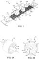
- the weighing system 10 includes a conveyor belt 12 advancing along a travel path from an upstream end 14 to a downstream end 15 in a travel direction 16.
- the conveyor belt 12 is a roller belt having a plurality of article-supporting belt rollers 18 extending above the belt's outer face.
- the belt rollers 18 shown in FIG. 1 are arranged to rotate on axes 20 oblique to the travel direction 16.
- roller belt with obliquely rotatable rollers is disclosed in U.S. Patent No. 6,968,941, "Apparatus and Methods for Conveying Objects," Matthew L. Fourney, Nov. 29, 2005 .
- the spherical rollers described in that patent rotate about all axes.
- Commercial versions include the INTRALOX ® Series 400 Ball Belt. Or the rollers can be stacked oblique rollers in which a bottom roller is actuated to rotate a top article-supporting roller in the opposite direction.
- a roller belt with stacked rollers is disclosed in U.S. Patent No. 7,360,641, "Conveyor Belt Having Rollers that Displace Objects," Matthew L. Fourney, Apr. 22, 2008 .
- Commercial versions include the INTRALOX ® Series 4550 DARB Belt.
- An infeed conveyor 22 feeds articles 24 onto the roller belt 12 at the upstream end 14 of the weighing system 10.
- the articles 24 sit atop the rollers 18 and are conveyed along a first length of the travel path through a weighing zone 26. Because the belt rollers 18 are not actuated in the weighing zone 26, the articles 24 pass through the weighing zone without being diverted from the travel direction 16 by the rollers. The articles 24 are weighed as they pass through the weighing zone 26.
- the conveyor belt 12 then conveys the articles into a second length of the travel path defined by a roller-actuation, or sorting, zone 28 downstream of the weighing zone 26.
- the roller-actuation zone 28 comprises two sequential roller-actuation subzones 28A, 28B.
- Actuators 30 in the roller-action zone 28 are selectively actuated and deactuated as a function of the weights of the articles atop the rollers.
- the actuator 30 when actuated, causes the belt rollers 18 to rotate on their axes 20 oblique to the travel direction and to push articles, such as out-of-range articles 24A, 24B whose weights are outside a predetermined acceptable weight range, off the side of the belt and onto reject conveyors 32A, 32B.
- Weights outside the acceptable weight range can be can be divided into two or more unacceptable subranges.
- the two roller-actuation zones as in the version shown in FIG. 1 could each correspond to one of two unacceptable weight ranges.
- All the out-of-range articles 24A whose weights are less than a predetermined unacceptable weight could be diverted in the first roller-actuation subzone 28A, and all those articles 28B whose weights exceed the predetermined unacceptable weight could be diverted off in the second subzone 28B.
- the rollers 18 supporting acceptable in-range articles 24" are deactuated as they pass through the roller-actuation zone 28.
- the acceptable articles are delivered over the conveyor's downstream end 15 to a discharge conveyor 34A, 34B. In that way rejected out-of-range articles 24A, 24B exit the conveyor belt 12 along a different path from the in-range articles 24C.
- roller-actuation subzones could be used to sort out-of-range articles to multiple reject conveyors according to out-of-range weight subranges into which they fall. Or the sorting can be organized according to other criteria, such as destination and package type, as just two examples.
- FIGS. 2A and 2B show a belt roller 18 with a weight sensor to measure the weights of articles.
- the cylindrical roller 18 is mounted on an axle 36 that defines the roller's axis of rotation 20.
- the weight sensor comprises three load cells 38, which are connected between the roller's periphery 40 and a hub 42 surrounding the axle 36.
- the three load cells 38 in this example are equi-spaced around the axle 36.
- the load cells 38 are electrically connected to associated support circuitry 44.
- the three load cells 38 resolve the downward force F, which is proportional to the weight of an article sitting atop the roller. The sums of the downward forces on all the rollers supporting an article equal the article's total weight.
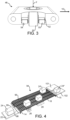
- the conveyor belt 12 shown in FIG. 1 is a modular conveyor belt constructed of a series of rows 46 of one or more belt modules, such as the module 48 shown in FIG. 3 .
- the rows 46 are hingedly linked together by hinge rods 49 at hinge joints.
- the roller 50 is mounted on an axle 52 that is oriented parallel to the travel direction 16.
- the ends of the axle 52 are supported from below on load cells 54, 55 embedded in the module 48.
- a downward force F on the article-supporting roller 50 is measured by the two load cells 54, 55.
- the sum of the outputs of the two load cells 54, 55 equals the applied force F.
- the load cells 54, 55 in FIG. 3 are associated with support circuitry to be described later.
- the weighing system 94 shown in FIG. 4 is operated as a conveyor switch.
- a roller conveyor belt 96 is divided across its width into two parallel longitudinal lanes 98, 99 that extend from the upstream end 14 to the downstream end 15.
- the infeed conveyor 22 feeds articles 24 onto the first lane 98 at the upstream end 14 of the conveyor belt 96.
- the articles 24 are weighed in the first lane 98 in the weighing zone 26.
- the roller-actuation zone 28 is selectively actuated either only for articles 24 whose weights are in-range or only for articles whose weights are out-of-range.
- the belt rollers 18 divert the articles from the first lane 98 to the second lane 99.
- the selectively diverted articles 24' are switched to the second lane 99 to exit the downstream end 15 of the conveyor belt 96 onto a discharge conveyor 101.
- the roller-actuation zone 28 is deactuated for articles 24" that are not selected to be switched to the second lane 99. Instead, those articles 24" remain in the first lane 98 to exit onto a separate discharge conveyor 102.
- the conveyor belt comprises two side-by-side abutting conveyor belts, in which the second conveyor belt can be, but does not have to be, a roller belt.
- FIG. 5 represents a passive system in which the belt has only passive components.
- a load cell 64 such as a load cell 38 as in FIGS. 2A and 2B or a load cell 54, 55 as in FIG. 3 , in the belt 12 is electrically connected to a transmitter 66 realized as a capacitor plate or a coil.
- a receiver 82 external to and below the belt 12 in the weighing zone is realized as a second capacitor plate forming a capacitor with the plate in the belt or as a second coil forming a transformer with the coil in the belt.
- the weight sensor's weight signal 70 is sent by the transmitter 66 to the external receiver 82 by capacitive or inductive coupling when the sensor 64 is in the weighing zone.
- the received weight signal is conditioned, including being converted from an analog weight signal 70' into a digital weight signal 71 in a conditioning circuit 72 before being sent to a controller 74, which may be realized as a programmable logic controller or other programmable computing device executing program steps stored in a program memory.
- the controller 74 also receives weight signals from other weight sensors and, from those signals, determines the weight of an article, compares its weight to a predetermined weight range, classifies the article as out-of-range if its weight is outside the weight range or as in-range if within, and selectively sends an actuation signal 76 to the actuator 30 in the actuation zone for either only the out-of-range articles or only the in-range articles to rotate the belt rollers to divert the in-range and out-of range articles off the belt along different exit paths.
- FIG. 6 Another version of support circuitry to transmit weight signals from the belt to the external controller 74 is shown in FIG. 6 .
- the circuitry on board the belt 12 includes the load cell 64, a local controller 78, and a transmitter 80.
- the analog weight signal 70 is converted to a digital weight signal 71 by the controller 78 and an associated analog-to-digital converter.
- the digital weight signal 71 is then transmitted by the transmitter to an external receiver 82 while the weight sensor is in the weighing zone.
- the received digital weight signal 71' passes through an interface circuit 84 on its way to the controller 74, which determines the weight of the article and either actuates or deactuates the belt rollers as they convey the article through the roller-actuation zone.
- the belt-borne components receive power from an external power supply 86, which is coupled to a power receiver 88 including a voltage regulator, in the belt.
- Power transfer to the power receiver 88 can be by inductive or capacitive coupling, by light transmission, or by sliding electrical contacts, as just a few examples.
- FIG. 7 shows a storage element 90, such as one or more dry cells or capacitors, powering the weight-sensor circuit.
- the external power source 86 is optionally coupled to a local charging circuit 92 in the belt to recharge the rechargeable storage element 90 wirelessly or via contacts.
- rollers have to be weighing rollers.
- the in-range rather than the out-of-range articles could be diverted off the side of the belt while the out-of-range articles pass straight through the roller-actuation zone and off the end of the belt.
- the rollers can be actuated to divert in-range articles off one side of the belt and out-of-range articles off the other side.
- different kinds of roller-actuation mechanisms can be used.
- a flat plat that is movable up and down into and out of contact with the belt rollers by a linear actuator can be used to actuate and deactuate the oblique belt rollers.
- the mechanism can raise and lower long actuating rollers whose axes of rotation are parallel to the travel direction into and out of contact with the oblique belt rollers to actuate and deactuate them.
- the roller-actuating mechanism can use shorter caster rollers whose axes of rotation are oriented oblique left or right to the travel direction to rotate the belt rollers to push articles off one side of the belt or the other.
- rollers can be made of electrically conductive or magnetic materials with poles and selectively actuated by a linear-motor stator in the roller-actuation zone. So, as these examples suggest, the invention is not meant to be limited to the exemplary versions described in detail.
Landscapes
- Engineering & Computer Science (AREA)
- Mechanical Engineering (AREA)
- Physics & Mathematics (AREA)
- General Physics & Mathematics (AREA)
- Sorting Of Articles (AREA)
- Control Of Conveyors (AREA)
Claims (14)
- Wiegesystem (10), das Folgendes aufweist:ein Förderband (12; 56), das zum Vorwärtsbewegen in einer Bewegungsrichtung (16) entlang eines Bewegungspfades von einem stromaufwärts gelegenen Ende (14) zu einem stromabwärts gelegenen Ende (15) angeordnet ist und eine Mehrzahl von artikeltragenden Rollen (18; 50; 58) hat, die zum Drehen zu einer eine Seite des Förderbands (12; 56) hin in einer Querrichtung quer zur Bewegungsrichtung (16) betätigt werden können;eine sich entlang einer ersten Länge des Bewegungspfads erstreckende Wiegezone (26), in der ein oder mehrere Gewichtssensoren die Gewichte von Artikeln (24) messen, die von dem Förderband (12; 56) befördert werden, und Gewichtssignale (70) erzeugen, die für die Gewichte der Artikel bezeichnend sind;eine Rollenbetätigungszone (28), die sich entlang einer zweiten Länge des Bewegungspfads erstreckt;wobei in der Rollenbetätigungszone (28) ein Stellantrieb (30) die artikeltragenden Rollen (18; 50; 58) beim Durchlaufen selektiv betätigt, um Artikel (24) in der Querrichtung zu schieben;dadurch gekennzeichnet, dass das Wiegesystem (10) eine Steuerung (74) aufweist:die die Gewichtssignale (70) empfängt;die die Gewichte der Artikel (24) anhand der Gewichtssignale (70) bestimmt;die die Rollenbetätigungszone (28) durchlaufenden Rollen (18; 50; 58) als eine Funktion der Gewichte der Artikel (24) selektiv betätigt und deaktiviert;wobei die Gewichtssensoren mit den Rollen (18; 50; 58) gekoppelt sind, um die Abwärtskräfte (F) zu messen, die von den beförderten Artikeln (24) oben auf den Rollen (18; 50) auf die Rollen (18; 50; 58) aufgebracht werden, wobei die Gewichtssignale (70) zu den Abwärtskräften (F) proportional sind.
- Wiegesystem (10) nach Anspruch 1, wobei a) die Rollenbetätigungszone (28) entlang der zweiten Länge sich stromabwärts von der Wiegezone (26) entlang der ersten Länge befindet; b) die Rollenbetätigungszone (28) entlang der zweiten Länge die Wiegezone (26) entlang der ersten Länge überlappt; oder c) die Rollenbetätigungszone (28) und die zweite Länge mit der Gewichtszone (26) und der ersten Länge übereinstimmen.
- Wiegesystem (10) nach Anspruch 1, wobei die Steuerung (74) die Gewichte eines vorbestimmten Gewichtsbereichs vergleicht, Artikel, deren Gewichte außerhalb des Gewichtsbereichs liegen, als außerhalb des Bereichs liegende Artikel und Artikel, deren Gewichte innerhalb des Gewichtsbereichs liegen, als innerhalb des Bereichs liegende Artikel klassifiziert und die die Rollenbetätigungszone (28) durchlaufenden artikeltragenden Rollen (18; 50) entweder für nur die außerhalb des Bereichs liegenden Artikel oder für nur die innerhalb des Bereichs liegenden Artikel zum Drehen in der Querrichtung betätigt, so dass die außerhalb des Bereichs liegenden Artikel und die innerhalb des Bereichs liegenden Artikel das Förderband (12) entlang verschiedener Pfade verlassen.
- Wiegesystem (10) nach Anspruch 3, wobei das Förderband (12) eine erste und eine zweite angrenzende Bahn (98, 99) hat, die sich vom stromaufwärts gelegenen Ende (14) zum stromabwärts gelegenen Ende (15) erstrecken, und wobei das Wiegesystem (10) Folgendes aufweist:einen Zuführförderer (22), der Artikel (24) am stromaufwärts gelegenen Ende (14) auf die erste Bahn (98) des Förderbandes (12) zuführt;wobei sich nur die erste Bahn (98) durch die Wiegezone (26) erstreckt;wobei die Steuerung (74) die die Rollenbetätigungszone (28) durchlaufenden artikeltragenden Rollen (18; 50) entweder nur für die außerhalb des Bereichs liegenden Artikel oder nur für die innerhalb des Bereichs liegenden Artikel betätigt, um entweder nur die außerhalb des Bereichs liegenden Artikel oder die innerhalb des Bereichs liegenden Artikel auf die zweite Bahn (99) zu leiten.
- Wiegesystem (10) nach Anspruch 1, das eine Mehrzahl von Rollenbetätigungsteilzonen (28A, 28B) in der Rollenbetätigungszone (28) aufweist oder eine Mehrzahl von Rollenbetätigungsteilzonen (28A, 28B) in der Rollenbetätigungszone (28) aufweist und wobei die Steuerung (74) die Gewichte mit einer Mehrzahl von vorbestimmten Gewichtsbereichen vergleicht, die jeweils einer der Rollenbetätigungsteilzonen (28A, 28B) entsprechen, und die die Rollenbetätigungsteilzone (28A, 28B) durchlaufenden artikeltragenden Rollen (18; 50) entsprechend dem Gewichtsbereich, in den das Gewicht jedes Artikels fällt, betätigt.
- Wiegesystem (10) nach Anspruch 1, wobei entweder:(a) das Förderband (12) Rollenachsen (36; 52), die zur Bewegungsrichtung (16) parallele oder schräge Achsen (20) definieren, beinhaltet, um die sich die artikeltragenden Rollen drehen (18; 50); oder(b) die Rollen gestapelte Rollen sind.
- Wiegesystem (10) nach Anspruch 1, wobei die Steuerung (74) sich außerhalb des Förderbands (12) befindet.
- Wiegesystem (1) nach Anspruch 7, das ferner Empfänger (82) beinhaltet, die sich außerhalb des Förderbands (12) befinden, und wobei die Gewichtssensoren in dem Förderband (12) montiert sind, um das Gewicht der Artikel (24) auf den Rollen (18; 50) zu messen, und wobei das Förderband (12) Transmitter (80) beinhaltet, die die Gewichtssignale (70) von den Gewichtssensoren empfangen und die Gewichtssignale (70) an die Empfänger (82) übertragen, die die Gewichtssignale (70) an die Steuerung (74) senden.
- Wiegesystem (10) nach Anspruch 8, wobei die Gewichtssensoren und die Transmitter (80) sich in den Rollen befinden.
- Wiegesystem (10) nach Anspruch 8, wobei das Förderband (12) Rollenachsen (52) beinhaltet, auf denen die Rollen (50) montiert sind, und wobei die Gewichtssensoren zwischen die Enden der Rollenachsen (52) und das Förderband (12) geschaltet sind.
- Wiegesystem (10) nach Anspruch 8, wobei das Förderband (12) lokale Steuerungen (78) zwischen den Gewichtssensoren und den Transmittern (80) beinhaltet, die die Gewichtssignale (70) in digitale Gewichtssignale (71) umwandeln, die von den Transmittern (80) an die Empfänger (82) übertragen werden.
- Förderband (12), das Folgendes aufweist:eine Reihe von Reihen (46) von einem oder mehreren Bandmodulen (48), die gelenkig miteinander verbunden sind;eine Mehrzahl von artikeltragenden Rollen (50), die im Band (12) montiert sind;gekennzeichnet durch eine Mehrzahl von Gewichtssensoren, die mit den Rollen (50) gekoppelt sind, um die Abwärtskräfte (F) zu messen, die von Artikeln (24) oben auf den Rollen (50) auf die Rollen (50) aufgebracht werden, und Gewichtssignale zu erzeugen, die proportional zu den Abwärtskräften (F) sind.
- Förderband (12) nach Anspruch 12, wobei die Gewichtssensoren in den Rollen (50) montiert sind; oder das ferner eine Mehrzahl von Rollenachsen (52) aufweist, auf denen die Rollen (50) drehbar montiert sind und wobei die Gewichtssensoren mit den Enden der Rollenachsen (52) verbunden sind.
- Förderband (12) nach Anspruch 12, das Transmitter (66; 80) aufweist, die die von den Gewichtssensoren erzeugten Gewichtssignale (70) empfangen und die Gewichtssignale (70) übertragen.
Applications Claiming Priority (2)
| Application Number | Priority Date | Filing Date | Title |
|---|---|---|---|
| US201762556585P | 2017-09-11 | 2017-09-11 | |
| PCT/US2018/047139 WO2019050667A1 (en) | 2017-09-11 | 2018-08-21 | WEIGHING ROLLER BELT CONVEYOR AND METHOD THEREOF |
Publications (3)
| Publication Number | Publication Date |
|---|---|
| EP3661667A1 EP3661667A1 (de) | 2020-06-10 |
| EP3661667A4 EP3661667A4 (de) | 2021-04-14 |
| EP3661667B1 true EP3661667B1 (de) | 2025-06-11 |
Family
ID=65634928
Family Applications (1)
| Application Number | Title | Priority Date | Filing Date |
|---|---|---|---|
| EP18853211.3A Active EP3661667B1 (de) | 2017-09-11 | 2018-08-21 | Wiege- und sortierrollenbandförderer |
Country Status (4)
| Country | Link |
|---|---|
| US (1) | US11142408B2 (de) |
| EP (1) | EP3661667B1 (de) |
| CN (1) | CN111093846B (de) |
| WO (1) | WO2019050667A1 (de) |
Families Citing this family (11)
| Publication number | Priority date | Publication date | Assignee | Title |
|---|---|---|---|---|
| US12024370B2 (en) * | 2018-05-16 | 2024-07-02 | Bel Usa, Llc | Automated shipping processor line and method for automatically shipping packages |
| CN109941703B (zh) * | 2019-04-16 | 2020-07-21 | 浙江创诺汽车零部件有限公司 | 一种铁路货车制动梁检修地下传输设备 |
| KR102739304B1 (ko) * | 2019-10-29 | 2024-12-05 | 한양대학교 에리카산학협력단 | 상황 인식 기반 보행자 검출 장치 및 방법 |
| JP7462927B2 (ja) * | 2020-04-08 | 2024-04-08 | 日本協同企画株式会社 | 果菜載せ体と果菜自動選別装置 |
| CN112027563A (zh) * | 2020-09-08 | 2020-12-04 | 厦门安科科技有限公司 | 一种具有超载警报和智能停机功能的输送装置 |
| CN112249448B (zh) * | 2020-11-03 | 2024-06-04 | 湖南达嘉智能包装设备有限公司 | 多列静态称重机 |
| US11814248B2 (en) | 2021-02-23 | 2023-11-14 | Intelligrated Headquarters, Llc | Methods, apparatuses, and systems for automatically detecting objects within a conveyor zone |
| CN113560206B (zh) * | 2021-06-07 | 2022-05-17 | 常州市佳乐车辆配件制造有限公司 | 一种汽车空调出风口拔片的智能自动检测设备 |
| CN113546860A (zh) * | 2021-06-19 | 2021-10-26 | 江西绿萌科技控股有限公司 | 一种用于水果重量分选装置 |
| CN114111978A (zh) * | 2021-11-29 | 2022-03-01 | 湖北省益欣盐产业技术研究院有限公司 | 一种食盐生产用称重装置 |
| AU2023225794A1 (en) * | 2022-02-28 | 2024-09-12 | FORTNA Systems, Inc. | System and method for transferring parcels |
Family Cites Families (26)
| Publication number | Priority date | Publication date | Assignee | Title |
|---|---|---|---|---|
| US3651936A (en) * | 1970-02-27 | 1972-03-28 | Bell & Howell Co | Sorter control circuit |
| ES2027274T3 (es) | 1986-12-24 | 1992-06-01 | M.A.F.(Materiel Pour L'arboriculture Fruitiere) S.A. | Aparato para la clasificacion automatica de productos agricolas tales como frutos. |
| US7007807B1 (en) * | 2003-01-29 | 2006-03-07 | Fmc Technologies, Inc. | Sorting system for multiple conveyor belts |
| US6968941B2 (en) * | 2003-11-21 | 2005-11-29 | Materials Handling Systems, Inc. | Apparatus and methods for conveying objects |
| US7249671B2 (en) * | 2005-05-06 | 2007-07-31 | Laitram, L.L.C. | Roller-belt conveyor for accumulating and moving articles laterally across the conveyor |
| US7344018B2 (en) | 2005-05-06 | 2008-03-18 | Laitram, L.L.C. | Conveyor and method for diverting closely spaced articles |
| US7360641B1 (en) | 2007-04-13 | 2008-04-22 | Laitram, L.L.C. | Conveyor belt having rollers that displace objects |
| BE1020295A3 (nl) | 2011-11-16 | 2013-07-02 | Acro Khlim | Werkwijze voor het sorteren van voorwerpen en sorteerinrichting daarvoor. |
| FR2991974B1 (fr) | 2012-06-15 | 2016-05-06 | Savoye | Systeme de convoyage modulaire, dispositif de controle et procede correspondants |
| EP2865616B1 (de) | 2012-06-21 | 2020-09-09 | Itoh Denki Co., Ltd. | Fördervorrichtung und gewichtsnachweisverfahren unter verwendung einer fördervorrichtung |
| CN203265083U (zh) * | 2013-04-19 | 2013-11-06 | 珠海市大航工业自动化技术有限公司 | 一种自动检重分选机 |
| US10191001B2 (en) | 2014-04-15 | 2019-01-29 | Laitram, L.L.C. | Conveyor-belt system for measuring conditions that vary the resonant frequency of a resonant circuit |
| US9493308B2 (en) * | 2014-08-11 | 2016-11-15 | Datalogic ADC, Inc. | Cross-belt system and automated item diversion |
| JP2016044056A (ja) * | 2014-08-25 | 2016-04-04 | 株式会社東芝 | 物品仕分装置 |
| CN204384398U (zh) * | 2014-09-19 | 2015-06-10 | 上海睿丰自动化系统有限公司 | 一种带式重型移载器 |
| DK3302830T3 (da) | 2015-06-04 | 2021-01-18 | Laitram Llc | Lim-sorterer efter vægt |
| CN109195886B (zh) | 2016-05-19 | 2021-08-06 | 伊东电机株式会社 | 输送装置 |
| CN205928921U (zh) * | 2016-06-29 | 2017-02-08 | 安吉县孝丰天友竹木机械制造厂 | 一种改进的竹木截断机 |
| CN106042077B (zh) * | 2016-06-29 | 2019-03-01 | 安吉县孝丰天友竹木机械制造厂 | 一种改进的竹木截断机 |
| CN206435490U (zh) * | 2016-09-29 | 2017-08-25 | 梅特勒-托利多仪器(上海)有限公司 | 剔除系统及其剔除器 |
| CN106379617B (zh) * | 2016-10-21 | 2019-05-24 | 江阴鑫宝利金属制品有限公司 | 复检备料线 |
| CN206184790U (zh) * | 2016-11-02 | 2017-05-24 | 四川喜之郎食品有限公司 | 不同规格产品的在线捡重系统 |
| CN106586381A (zh) * | 2016-12-23 | 2017-04-26 | 上海利来链条有限公司 | 一种带滚珠万向转弯输送网带 |
| US10532894B2 (en) * | 2017-03-10 | 2020-01-14 | Regal Beloit America, Inc. | Modular transfer units, systems, and methods |
| CN109896297B (zh) * | 2017-12-08 | 2021-03-16 | 泰科电子(上海)有限公司 | 自动供料系统 |
| CN110864778A (zh) * | 2019-11-26 | 2020-03-06 | 徐州英孚测控工程有限公司 | 一种皮带称重装置 |
-
2018
- 2018-08-21 EP EP18853211.3A patent/EP3661667B1/de active Active
- 2018-08-21 WO PCT/US2018/047139 patent/WO2019050667A1/en not_active Ceased
- 2018-08-21 US US16/640,445 patent/US11142408B2/en active Active
- 2018-08-21 CN CN201880058645.7A patent/CN111093846B/zh active Active
Also Published As
| Publication number | Publication date |
|---|---|
| EP3661667A1 (de) | 2020-06-10 |
| CN111093846B (zh) | 2021-12-24 |
| CN111093846A (zh) | 2020-05-01 |
| US11142408B2 (en) | 2021-10-12 |
| US20200189861A1 (en) | 2020-06-18 |
| EP3661667A4 (de) | 2021-04-14 |
| WO2019050667A1 (en) | 2019-03-14 |
Similar Documents
| Publication | Publication Date | Title |
|---|---|---|
| EP3661667B1 (de) | Wiege- und sortierrollenbandförderer | |
| US10226795B2 (en) | Vision based item typing and separation system | |
| US9809388B2 (en) | Cross belt slat sorter | |
| CA2388525C (en) | Double width crossbelt sorter | |
| US20190202642A1 (en) | Off-loading, typing and item separation system | |
| US20190193945A1 (en) | Vision based article typing and sorting system | |
| CN100490998C (zh) | 传输农产品并适于至少根据重量拣选农产品的装置 | |
| US4792049A (en) | System and process for sorting and conveying articles | |
| CA2954270C (en) | High rate bulk flow sortation | |
| EP3621904A2 (de) | Artikeltypisierungs- und sortierungssystem auf sichtbasis | |
| US20220297160A1 (en) | Compact sorter | |
| US3910402A (en) | Routing and conveying apparatus | |
| US6557724B1 (en) | Vertical conveyor | |
| EP3837194B1 (de) | Gittersortierer | |
| EP2999650B1 (de) | Vorrichtung zur dynamischen steuerung des abstands von geförderten objekten | |
| WO1998049076A3 (en) | Conveyor having a cushioned belt and high speed discharge capabilities | |
| US20160288172A1 (en) | Sorter with double runout lanes in each bullpen and method for sorting | |
| EP1368236A1 (de) | System zum vorsortieren von produkten, wie früchten, und zum füllen von behältern mit diesen produkten | |
| EP0803716A2 (de) | Vorrichtung zum dynamischen Wägen von Früchten | |
| EP1831089B1 (de) | Positionierförderer | |
| CN117302928A (zh) | 用于传送和调整所传送的商品的定位和/或间距的传送器系统和方法 |
Legal Events
| Date | Code | Title | Description |
|---|---|---|---|
| STAA | Information on the status of an ep patent application or granted ep patent |
Free format text: STATUS: THE INTERNATIONAL PUBLICATION HAS BEEN MADE |
|
| PUAI | Public reference made under article 153(3) epc to a published international application that has entered the european phase |
Free format text: ORIGINAL CODE: 0009012 |
|
| STAA | Information on the status of an ep patent application or granted ep patent |
Free format text: STATUS: REQUEST FOR EXAMINATION WAS MADE |
|
| 17P | Request for examination filed |
Effective date: 20200213 |
|
| AK | Designated contracting states |
Kind code of ref document: A1 Designated state(s): AL AT BE BG CH CY CZ DE DK EE ES FI FR GB GR HR HU IE IS IT LI LT LU LV MC MK MT NL NO PL PT RO RS SE SI SK SM TR |
|
| AX | Request for extension of the european patent |
Extension state: BA ME |
|
| DAV | Request for validation of the european patent (deleted) | ||
| DAX | Request for extension of the european patent (deleted) | ||
| A4 | Supplementary search report drawn up and despatched |
Effective date: 20210317 |
|
| RIC1 | Information provided on ipc code assigned before grant |
Ipc: B07C 5/22 20060101AFI20210311BHEP Ipc: B07C 5/36 20060101ALI20210311BHEP Ipc: B65G 69/20 20060101ALI20210311BHEP Ipc: G01G 11/00 20060101ALI20210311BHEP |
|
| STAA | Information on the status of an ep patent application or granted ep patent |
Free format text: STATUS: EXAMINATION IS IN PROGRESS |
|
| 17Q | First examination report despatched |
Effective date: 20230905 |
|
| GRAP | Despatch of communication of intention to grant a patent |
Free format text: ORIGINAL CODE: EPIDOSNIGR1 |
|
| STAA | Information on the status of an ep patent application or granted ep patent |
Free format text: STATUS: GRANT OF PATENT IS INTENDED |
|
| GRAJ | Information related to disapproval of communication of intention to grant by the applicant or resumption of examination proceedings by the epo deleted |
Free format text: ORIGINAL CODE: EPIDOSDIGR1 |
|
| STAA | Information on the status of an ep patent application or granted ep patent |
Free format text: STATUS: EXAMINATION IS IN PROGRESS |
|
| INTG | Intention to grant announced |
Effective date: 20250103 |
|
| GRAP | Despatch of communication of intention to grant a patent |
Free format text: ORIGINAL CODE: EPIDOSNIGR1 |
|
| STAA | Information on the status of an ep patent application or granted ep patent |
Free format text: STATUS: GRANT OF PATENT IS INTENDED |
|
| INTC | Intention to grant announced (deleted) | ||
| INTG | Intention to grant announced |
Effective date: 20250211 |
|
| GRAS | Grant fee paid |
Free format text: ORIGINAL CODE: EPIDOSNIGR3 |
|
| P01 | Opt-out of the competence of the unified patent court (upc) registered |
Free format text: CASE NUMBER: APP_15037/2025 Effective date: 20250327 |
|
| GRAA | (expected) grant |
Free format text: ORIGINAL CODE: 0009210 |
|
| STAA | Information on the status of an ep patent application or granted ep patent |
Free format text: STATUS: THE PATENT HAS BEEN GRANTED |
|
| AK | Designated contracting states |
Kind code of ref document: B1 Designated state(s): AL AT BE BG CH CY CZ DE DK EE ES FI FR GB GR HR HU IE IS IT LI LT LU LV MC MK MT NL NO PL PT RO RS SE SI SK SM TR |
|
| REG | Reference to a national code |
Ref country code: GB Ref legal event code: FG4D |
|
| REG | Reference to a national code |
Ref country code: CH Ref legal event code: EP |
|
| REG | Reference to a national code |
Ref country code: IE Ref legal event code: FG4D |
|
| REG | Reference to a national code |
Ref country code: DE Ref legal event code: R096 Ref document number: 602018082567 Country of ref document: DE |
|
| PG25 | Lapsed in a contracting state [announced via postgrant information from national office to epo] |
Ref country code: FI Free format text: LAPSE BECAUSE OF FAILURE TO SUBMIT A TRANSLATION OF THE DESCRIPTION OR TO PAY THE FEE WITHIN THE PRESCRIBED TIME-LIMIT Effective date: 20250611 Ref country code: ES Free format text: LAPSE BECAUSE OF FAILURE TO SUBMIT A TRANSLATION OF THE DESCRIPTION OR TO PAY THE FEE WITHIN THE PRESCRIBED TIME-LIMIT Effective date: 20250611 |
|
| PGFP | Annual fee paid to national office [announced via postgrant information from national office to epo] |
Ref country code: DE Payment date: 20250625 Year of fee payment: 8 |
|
| REG | Reference to a national code |
Ref country code: LT Ref legal event code: MG9D |
|
| PG25 | Lapsed in a contracting state [announced via postgrant information from national office to epo] |
Ref country code: NO Free format text: LAPSE BECAUSE OF FAILURE TO SUBMIT A TRANSLATION OF THE DESCRIPTION OR TO PAY THE FEE WITHIN THE PRESCRIBED TIME-LIMIT Effective date: 20250911 Ref country code: GR Free format text: LAPSE BECAUSE OF FAILURE TO SUBMIT A TRANSLATION OF THE DESCRIPTION OR TO PAY THE FEE WITHIN THE PRESCRIBED TIME-LIMIT Effective date: 20250912 |
|
| REG | Reference to a national code |
Ref country code: NL Ref legal event code: MP Effective date: 20250611 |
|
| PG25 | Lapsed in a contracting state [announced via postgrant information from national office to epo] |
Ref country code: BG Free format text: LAPSE BECAUSE OF FAILURE TO SUBMIT A TRANSLATION OF THE DESCRIPTION OR TO PAY THE FEE WITHIN THE PRESCRIBED TIME-LIMIT Effective date: 20250611 |
|
| PGFP | Annual fee paid to national office [announced via postgrant information from national office to epo] |
Ref country code: GB Payment date: 20250710 Year of fee payment: 8 |
|
| PG25 | Lapsed in a contracting state [announced via postgrant information from national office to epo] |
Ref country code: HR Free format text: LAPSE BECAUSE OF FAILURE TO SUBMIT A TRANSLATION OF THE DESCRIPTION OR TO PAY THE FEE WITHIN THE PRESCRIBED TIME-LIMIT Effective date: 20250611 |
|
| PGFP | Annual fee paid to national office [announced via postgrant information from national office to epo] |
Ref country code: FR Payment date: 20250709 Year of fee payment: 8 |
|
| PG25 | Lapsed in a contracting state [announced via postgrant information from national office to epo] |
Ref country code: RS Free format text: LAPSE BECAUSE OF FAILURE TO SUBMIT A TRANSLATION OF THE DESCRIPTION OR TO PAY THE FEE WITHIN THE PRESCRIBED TIME-LIMIT Effective date: 20250911 |
|
| PG25 | Lapsed in a contracting state [announced via postgrant information from national office to epo] |
Ref country code: LV Free format text: LAPSE BECAUSE OF FAILURE TO SUBMIT A TRANSLATION OF THE DESCRIPTION OR TO PAY THE FEE WITHIN THE PRESCRIBED TIME-LIMIT Effective date: 20250611 |
|
| PG25 | Lapsed in a contracting state [announced via postgrant information from national office to epo] |
Ref country code: NL Free format text: LAPSE BECAUSE OF FAILURE TO SUBMIT A TRANSLATION OF THE DESCRIPTION OR TO PAY THE FEE WITHIN THE PRESCRIBED TIME-LIMIT Effective date: 20250611 |
|
| PG25 | Lapsed in a contracting state [announced via postgrant information from national office to epo] |
Ref country code: PT Free format text: LAPSE BECAUSE OF FAILURE TO SUBMIT A TRANSLATION OF THE DESCRIPTION OR TO PAY THE FEE WITHIN THE PRESCRIBED TIME-LIMIT Effective date: 20251013 |
|
| REG | Reference to a national code |
Ref country code: AT Ref legal event code: MK05 Ref document number: 1801970 Country of ref document: AT Kind code of ref document: T Effective date: 20250611 |