EP3661616B1 - Automatisierte geführte fahrzeuge - Google Patents
Automatisierte geführte fahrzeuge Download PDFInfo
- Publication number
- EP3661616B1 EP3661616B1 EP18756478.6A EP18756478A EP3661616B1 EP 3661616 B1 EP3661616 B1 EP 3661616B1 EP 18756478 A EP18756478 A EP 18756478A EP 3661616 B1 EP3661616 B1 EP 3661616B1
- Authority
- EP
- European Patent Office
- Prior art keywords
- guided vehicle
- automated guided
- passenger carrying
- capacitor
- charging
- Prior art date
- Legal status (The legal status is an assumption and is not a legal conclusion. Google has not performed a legal analysis and makes no representation as to the accuracy of the status listed.)
- Active
Links
Images


Classifications
-
- A—HUMAN NECESSITIES
- A63—SPORTS; GAMES; AMUSEMENTS
- A63G—MERRY-GO-ROUNDS; SWINGS; ROCKING-HORSES; CHUTES; SWITCHBACKS; SIMILAR DEVICES FOR PUBLIC AMUSEMENT
- A63G25/00—Autocar-like self-drivers; Runways therefor
-
- A—HUMAN NECESSITIES
- A63—SPORTS; GAMES; AMUSEMENTS
- A63G—MERRY-GO-ROUNDS; SWINGS; ROCKING-HORSES; CHUTES; SWITCHBACKS; SIMILAR DEVICES FOR PUBLIC AMUSEMENT
- A63G7/00—Up-and-down hill tracks; Switchbacks
-
- B—PERFORMING OPERATIONS; TRANSPORTING
- B60—VEHICLES IN GENERAL
- B60L—PROPULSION OF ELECTRICALLY-PROPELLED VEHICLES; SUPPLYING ELECTRIC POWER FOR AUXILIARY EQUIPMENT OF ELECTRICALLY-PROPELLED VEHICLES; ELECTRODYNAMIC BRAKE SYSTEMS FOR VEHICLES IN GENERAL; MAGNETIC SUSPENSION OR LEVITATION FOR VEHICLES; MONITORING OPERATING VARIABLES OF ELECTRICALLY-PROPELLED VEHICLES; ELECTRIC SAFETY DEVICES FOR ELECTRICALLY-PROPELLED VEHICLES
- B60L50/00—Electric propulsion with power supplied within the vehicle
- B60L50/40—Electric propulsion with power supplied within the vehicle using propulsion power supplied by capacitors
-
- B—PERFORMING OPERATIONS; TRANSPORTING
- B60—VEHICLES IN GENERAL
- B60L—PROPULSION OF ELECTRICALLY-PROPELLED VEHICLES; SUPPLYING ELECTRIC POWER FOR AUXILIARY EQUIPMENT OF ELECTRICALLY-PROPELLED VEHICLES; ELECTRODYNAMIC BRAKE SYSTEMS FOR VEHICLES IN GENERAL; MAGNETIC SUSPENSION OR LEVITATION FOR VEHICLES; MONITORING OPERATING VARIABLES OF ELECTRICALLY-PROPELLED VEHICLES; ELECTRIC SAFETY DEVICES FOR ELECTRICALLY-PROPELLED VEHICLES
- B60L53/00—Methods of charging batteries, specially adapted for electric vehicles; Charging stations or on-board charging equipment therefor; Exchange of energy storage elements in electric vehicles
-
- B—PERFORMING OPERATIONS; TRANSPORTING
- B60—VEHICLES IN GENERAL
- B60L—PROPULSION OF ELECTRICALLY-PROPELLED VEHICLES; SUPPLYING ELECTRIC POWER FOR AUXILIARY EQUIPMENT OF ELECTRICALLY-PROPELLED VEHICLES; ELECTRODYNAMIC BRAKE SYSTEMS FOR VEHICLES IN GENERAL; MAGNETIC SUSPENSION OR LEVITATION FOR VEHICLES; MONITORING OPERATING VARIABLES OF ELECTRICALLY-PROPELLED VEHICLES; ELECTRIC SAFETY DEVICES FOR ELECTRICALLY-PROPELLED VEHICLES
- B60L53/00—Methods of charging batteries, specially adapted for electric vehicles; Charging stations or on-board charging equipment therefor; Exchange of energy storage elements in electric vehicles
- B60L53/10—Methods of charging batteries, specially adapted for electric vehicles; Charging stations or on-board charging equipment therefor; Exchange of energy storage elements in electric vehicles characterised by the energy transfer between the charging station and the vehicle
-
- G—PHYSICS
- G05—CONTROLLING; REGULATING
- G05D—SYSTEMS FOR CONTROLLING OR REGULATING NON-ELECTRIC VARIABLES
- G05D1/00—Control of position, course, altitude or attitude of land, water, air or space vehicles, e.g. using automatic pilots
- G05D1/02—Control of position or course in two dimensions
- G05D1/021—Control of position or course in two dimensions specially adapted to land vehicles
- G05D1/0212—Control of position or course in two dimensions specially adapted to land vehicles with means for defining a desired trajectory
- G05D1/0217—Control of position or course in two dimensions specially adapted to land vehicles with means for defining a desired trajectory in accordance with energy consumption, time reduction or distance reduction criteria
-
- H—ELECTRICITY
- H02—GENERATION; CONVERSION OR DISTRIBUTION OF ELECTRIC POWER
- H02J—ELECTRIC POWER NETWORKS; CIRCUIT ARRANGEMENTS OR SYSTEMS FOR SUPPLYING OR DISTRIBUTING ELECTRIC POWER; SYSTEMS FOR STORING ELECTRIC ENERGY
- H02J7/00—Circuit arrangements for charging or discharging batteries or for supplying loads from batteries
- H02J7/34—Parallel operation in networks using both storage and other DC sources, e.g. providing buffering
- H02J7/345—Parallel operation in networks using both storage and other DC sources, e.g. providing buffering using capacitors as storage or buffering devices
-
- H—ELECTRICITY
- H02—GENERATION; CONVERSION OR DISTRIBUTION OF ELECTRIC POWER
- H02P—CONTROL OR REGULATION OF ELECTRIC MOTORS, ELECTRIC GENERATORS OR DYNAMO-ELECTRIC CONVERTERS; CONTROLLING TRANSFORMERS, REACTORS OR CHOKE COILS
- H02P3/00—Arrangements for stopping or slowing electric motors, generators, or dynamo-electric converters
- H02P3/06—Arrangements for stopping or slowing electric motors, generators, or dynamo-electric converters for stopping or slowing an individual dynamo-electric motor or dynamo-electric converter
- H02P3/08—Arrangements for stopping or slowing electric motors, generators, or dynamo-electric converters for stopping or slowing an individual dynamo-electric motor or dynamo-electric converter for stopping or slowing a DC motor
- H02P3/14—Arrangements for stopping or slowing electric motors, generators, or dynamo-electric converters for stopping or slowing an individual dynamo-electric motor or dynamo-electric converter for stopping or slowing a DC motor by regenerative braking
-
- A—HUMAN NECESSITIES
- A63—SPORTS; GAMES; AMUSEMENTS
- A63G—MERRY-GO-ROUNDS; SWINGS; ROCKING-HORSES; CHUTES; SWITCHBACKS; SIMILAR DEVICES FOR PUBLIC AMUSEMENT
- A63G31/00—Amusement arrangements
- A63G31/16—Amusement arrangements creating illusions of travel
-
- Y—GENERAL TAGGING OF NEW TECHNOLOGICAL DEVELOPMENTS; GENERAL TAGGING OF CROSS-SECTIONAL TECHNOLOGIES SPANNING OVER SEVERAL SECTIONS OF THE IPC; TECHNICAL SUBJECTS COVERED BY FORMER USPC CROSS-REFERENCE ART COLLECTIONS [XRACs] AND DIGESTS
- Y02—TECHNOLOGIES OR APPLICATIONS FOR MITIGATION OR ADAPTATION AGAINST CLIMATE CHANGE
- Y02T—CLIMATE CHANGE MITIGATION TECHNOLOGIES RELATED TO TRANSPORTATION
- Y02T10/00—Road transport of goods or passengers
- Y02T10/60—Other road transportation technologies with climate change mitigation effect
- Y02T10/70—Energy storage systems for electromobility, e.g. batteries
Definitions
- the present invention relates to automated guided vehicles, hereinafter referred to as AGVs, and specifically to AGVs used for entertainment purposes. More specifically, the present invention relates to automated guided vehicles being powered by at least one electric motor.
- the invention also relates to a system of automated guided vehicles comprising at least one automated guided vehicle and at least one charging station. The invention also relates to method steps carried out to control an AGV.
- Theme park rides typically utilise passenger carrying AGVs to provide an immersive entertainment experience.
- the AGV moves through a workspace or themed environment and its movement is synchronised with elements of the themed environment.
- elements may include, for example, scenery, props, animatronics, audio effects, visual or media based effects, pyrotechnic effects and olfactory effects.
- the vehicle is autonomously guided in so far that it its movement over a surface is not defined and constrained by a physical track.
- a track may include, for example, one or more rails or channels.
- the vehicle preferably has a programmable control system which may govern the movement of the AGV.
- the carrier may be a passenger carrier.
- the passenger carrier may be configured so as to carry a single passenger.
- the passenger carrier may be configured so as to accommodate multiple passengers.
- the passenger carrier preferably includes safety restraints for passengers either individually or in adjacent groups.
- Passenger carrying manipulators are well known, and are exemplified in the current art by, for example, PCT/GB2013/052989 .
- an autonomously guided vehicle may include an on-board power source.
- the on-board power source may consist of one or more batteries.
- Said one or more batteries may include lead acid, nickel metal hydride or lithium ion type.
- the capacity of the batteries is usually chosen to last for a full working period of the AGV, e.g. the opening hours of the amusement park.
- the AGVs may complete a high number of rides, e.g.
- a passenger embarkation station to allow passengers to board the AGV, moving through the themed environment and subjecting the passenger to a number of predefined motions or movement, allowing the passengers to disembark at the station and returning to the embark station.
- Such a cycle may take in the range of two to ten minutes.
- the batteries of the AGV are continuously discharged by these rides.
- the AGVs are recharged between the end of a working period and the beginning of the next working period, e.g. during the closing hours of the amusement park. This may give twelve to fourteen hours of recharging time.
- the capacity of the batteries has to be chosen to be sufficiently high, which increases weight and corresponding inertial penalties as well as the commercial costs for the batteries.
- the autonomously guided vehicle may be powered by a remote, off board power source.
- the autonomously guided vehicle may be powered by an overhead electrified grid system with conductive floor and an overhead power pick up device.
- the autonomously guided vehicle may be powered by an in floor inductive power pick up device.
- off board power sources provide further technical challenges, for example passenger safety.
- the available current provided by inductive pick-ups is typically limited in the low kW range, then the system must be perfectly aligned to the inductive coils for optimal efficiency.
- US2010/308769 discloses a method for managing charge of a plurality of AGVs circulating on a main route.
- An automatic charge station to charge the batteries of the AGVs is provided in a charge route which is a sub-route branched off of the main route.
- the invention at least mitigates the problems of the prior art by providing passenger carrying automated guided vehicles with at least one capacitor as a power source for electrical consumers of the passenger carrying automated guided vehicle, particularly for at least one electric motor that propels the passenger carrying automated guided vehicle.
- the advantage of the invention is that the at least one capacitor allows very high charging currents. Batteries store electrical energy in an electrochemical process, which is reversible as long as the charging current remains below a given limit. When the charging current exceeds the given limit, the electrochemical process changes into another electrochemical process, which is irreversible and the battery may eventually be even destroyed, or become non-viable.
- Using a capacitor as a power source does not require an electrochemical process and allows a much higher charging current than a conventional battery based on an electrochemical process. Therefore, the charging time is greatly reduced in comparison to a conventional battery and is essentially limited by the charging system. This allows the bank of capacitors to recharge several times during the working period and to extend the time of the working period beyond eight to ten hours. In fact, due to the short recharging time, an AGV with a capacitor as a power source would be operable 24 hours, 7 days a week, interrupted only by short pre-planned recharging intervals.
- a plurality of capacitors may be used, in series or in parallel.
- the aforementioned capacitor is therefore referred to as a bank of capacitors.
- the bank of capacitors may consist of only a single capacitor. So far, however, even a single capacitor, commonly called “super capacitor” or “ultra-capacitor”, is effectively a composition of a plurality of capacitors.
- the passenger carrying automated guided vehicle comprises a charging module for charging the bank of capacitors.
- This charging module is specially adapted to the needs of the bank of capacitors.
- the passenger carrying automated guided vehicle comprises charging contacts for electrically contacting to an external charging station.
- the bank of capacitors can be charged in-between the working period of the AGV.
- the charging contacts are designed as sliding contacts for connecting to a charging rail
- the bank of capacitors may be charged when the AGV is following a specific charging path where power rails may be arranged at the side wall of a charging station and are configured to mate with the charging contacts arranged on the side wall of a body of the automated guided vehicle.
- the power rail may also be located at the floor or ceiling of the charging station.
- the charging path may be located in-between the disembarkation station, where all passengers have to leave the AGV, and the embarkation station, whereupon new passengers are allowed to embark the AGV.
- the AGV As no passengers are allowed in-between stations and the live contacts are carefully protected, passengers are not exposed to any risks presented by accidental exposure to live wires, rails or contacts.
- this allows the AGV to charge whilst the AGV is moving between passenger disembarkation and embarkation points thus minimising any delays to the passengers whilst the AGV charges.
- the passenger carrying automated guided vehicle alternatively may comprise contactless charging means for contactless transferral of energy from an external charging station.
- These means may be an induction loop in the AGV and an induction loop in the floor.
- the AGV may follow for a short time a charging path defined by the induction loop and is recharged while following this charging path.
- this charging path may be part of the animated path when carrying passengers.
- the bank of capacitors of the passenger carrying automated guided vehicle is charged up to a high voltage in the range of, for example, 500 to 700 Volts. This could correspond to the peak-to-peak voltage of approximately 565 Volts that a charging station may produce as a charging voltage from an AC voltage of 400 Volts, the usual three-phase mains electricity in Europe. Compared to the nominal voltage of 12 to 48 Volts of the typically used batteries, the combination of the high charging current of the bank of capacitors and the high voltages and power that can be extracted from a fully charged bank of capacitors is significantly increased.
- the preferred charging voltage of the bank of capacitors may be approximately 678 Volts.
- the charging station may comprise a voltage converter that would allow a higher voltage of, for example, 690 Volts or even to use the maximum voltage that the bank of capacitors can be charged with.
- the passenger carrying automated guided vehicle is equipped with at least one high voltage electric motor, the nominal voltage of which is essentially 400 Volts.
- These industrial voltage motors are in widespread use for industrial automation and may be used for powering larger AGVs with a heavier payload. Due to practical reasons the batteries of AGVs were never connected in series to provide very high voltages, and AGV applications utilise low voltage motors instead. Thus by using the at least one high voltage electric motor a higher powered AGV may be provided.
- the capacitor feeds power directly to the DC inputs (DC bus) of the motor controller, thus allowing the use of a wide range of the more efficient high voltage (400V plus) motors on a mobile systems.
- the passenger carrying automated guided vehicle further comprises a converter or drive that essentially converts the DC varying capacitor voltages into sinusoidal waveforms to develop power and torque to make the electrical motor deliver the commanded speed.
- the drive system has been designed to allow for a widely varying input voltage such as is typical for a capacitor bank, for example, by pulse width modulation to maximally exploit the stored energy of the bank of capacitors. This helps ensure that the performance of the vehicle remains unchanged/constant for a wide range of capacitor voltages and/or discharging voltage states of the capacitor.
- the converter may include means for up converting voltage lower than required by the motors, and this exploits modes of the energy stored in the capacitors.
- the DC voltage bus of the motor drive amplifiers of the passenger carrying automated guided vehicle may be fed high voltage DC power directly from the capacitor bank, thus negating the requirement of any power conditioning or voltage set up or down conversions.
- the setup allows for highly efficient regenerative braking and energy recovery. Furthermore, the efficiency of this process is much higher than in the case of conventional battery technology where regenerative efficiency is mainly determined and limited by electrochemical processes.
- the passenger carrying automated guided vehicle is operable to follow a predetermined path over a floor, from a start point to an end point thus defining the route which the automated guided vehicle travels.
- the automated guided vehicle is further being operable on the way back from the end point to the start point A to frequent a charging station for recharging the at least one bank of capacitors at the charging station.
- Such a route defines a charging path for the AGV.
- the AGV may therefore complete a number of working cycles and be guided on a charging path only so often when the power remaining in the bank of capacitors is almost exhausted.
- the passenger carrying automated guided vehicle is adapted to follow a path over a floor from a start point to an end point which the automated guided vehicle is intended to travel.
- the AGV comprises a charge control module for measuring a remaining capacity of the bank of capacitors, for example at the end point, comparing the measured capacity with a pre-defined value that indicates the minimum capacity needed for a AGV to complete a full tour, for example from the end point to the start point, from the start point to the end point, and from the end point to a charging station.
- the charge control module determines that the measured remaining capacity is below the pre-defined capacity, the charge control module instructs the AGV to follow a route a charging station.
- the bank of capacitors of the passenger carrying automated guided vehicle is arranged in a removable assembly. This allows for example to use two banks of capacitors for one AGV. One bank of capacitors is charged externally, while a second bank of capacitors is used in the AGV as the power source. When the AGV passes the charging station, the discharged bank of capacitors is replaced by the second bank of capacitors and the discharged bank of capacitors is recharged. This gives as much time for charging one of the bank of capacitors as the time of discharging the other bank of capacitors during a working cycle.
- the invention also relates to a system of at least one passenger carrying automated guided vehicles with at least one capacitor as a power source for electrical consumers of the passenger carrying automated guided vehicle, and a charging station adapted for charging the capacitor of the passenger carrying automated guided vehicles.
- the system may further comprise guiding means for defining a travel path having a start point and an end point, and a return path between the end point and the start point.
- the guiding means are adapted to provide a charging path that the AGV has to follow for recharging the capacitor of the AGV at the charging station.
- the guiding means for example, define the charging path preferably between the end point and the start point.
- the charge path may follow the normal return path between the end point and the start point. This would be the case if the AGV has to be recharged after each completion of a working run between the start point and the end point.
- the charge path may be different to the return path. This would be a preferred solution especially when the AGV has to be recharged only after a number of completed working runs.
- the AGVs that do not need to be recharged are guided along the return path and those which need to be recharged are guided along the charge path. This allows, for example, the AGV to use more time in the charge path for recharging and allow the other AGVs, which do not need to recharge, to run more quickly through the return path.
- the invention also relates to a method of operating a passenger carrying automated guided vehicle comprising the steps of providing the passenger carrying automated guided vehicle with a capacitor as a source for electrical energy; charging the capacitor of the passenger carrying automated guided vehicle with electrical energy; using the electrical energy stored in the capacitor to supply to the electrical motors of the passenger carrying automated guided vehicle.
- the method for operating a passenger carrying automated guided vehicle may further include the steps of guiding the passenger carrying automated guided vehicle along a defined travel path from a start point to an end point; guiding the passenger carrying automated guided vehicle from the end point to a charging station and recharging the capacitor of the passenger carrying automated guided vehicle; guiding the passenger carrying automated guided vehicle from the charging station to the start point.
- the method for operating a passenger carrying automated guided vehicle may further include the steps of measuring the remaining capacity of the capacitor of the passenger carrying automated guided vehicle; comparing the measured remaining capacity of the passenger carrying automated guided vehicle with a pre-defined value; in case the measured remaining capacity of the capacitor of the passenger carrying automated guided vehicle is below the pre-defined threshold, causing the passenger carrying automated guided vehicle to travel to a charging station for recharging the capacitor of the passenger carrying automated guided vehicle.
- the method of operating a passenger carrying automated guided vehicle further includes the steps of measuring the remaining capacity of the capacitor of the passenger carrying automated guided vehicle and comparing the measured remaining capacity of the passenger carrying automated guided vehicle with a pre-defined value. In case the measured remaining capacity of the capacitor of the passenger carrying automated guided vehicle is below the pre-defined threshold, the passenger carrying automated guided vehicle is caused to travel to a charging station for recharging the capacitor of the passenger carrying automated guided vehicle.
- These method steps increase the autonomy of the AGV, as each AGV decides individually before it starts a new working cycle, whether sufficient energy is left to perform another working cycle or if it is time to get recharged.
- load variations passingengers with lower weight, such as children and passengers with higher weight, such as adults
- variations in the distances travelled by the AGV from a start point to an end point for example, when different paths are possible between the start and end points.
- the system provides wires embedded in a surface over which the passenger carrying automated guided vehicle is intended to travel for defining a limit for the AGV.
- the system broadcasts a radio signal using the wires as a transmit antenna.
- a safety controller is adapted to stop the AGV in the event that the peripheral sensor fails to detect the radio signal broadcast by the limit defining wire.
- a passenger carrying automated guided vehicle used for entertainment purposes is propelled by at least one electric motor, wherein the automated guided vehicle comprises at least one capacitor as a power source for the at least one electric motor and attendant motor controller (a controller associated with the electric motor), whereby the capacitor feeds power directly to the DC inputs of the motor controller, allowing the use of a wide range of more efficient high voltage motors, for example electrical motors with a nominal supply voltage of 400Volts and more.
- a capacitor can be easily sized for a higher voltage as capacitors are available with a far higher nominal voltage than a battery cell.
- the automated guided vehicle is propelled by at least one electric motor, wherein the automated guided vehicle comprises at least one capacitor as a power source for the at least one electric motor and attendant motor controller, whereby the motor feeds regenerative braking currents directly back into the capacitor from the DC bus.
- regenerative braking currents significantly improves efficiency and endurance of the AGV in comparison to prior art AGVs.
- the automated guided vehicle is propelled by at least one electric motor, wherein the automated guided vehicle comprises at least one capacitor as a power source for the at least one electric motor and attendant motor controller.
- the AGV comprises one or more safety isolation units.
- Each safety isolation unit comprises, for example, a pair of redundant high-voltage contactors.
- the safety isolation units are monitored and controlled via an on-board safety PLC system, thereby ensuring that the capacitor can be safely disconnected from both the charging system input and the motor controller DC bus output, for example in a detected emergency situation with a shutdown of the system or during maintenance interventions. This aspect of the invention ensures that the capacitor cannot accidentally discharge during maintenance interventions or shutdowns.
- the automated guided vehicle being propelled by at least one electric motor comprises a capacitor based power module, such power module incorporating a series load, for example, a high-pulse-load pre-charge resistor, to limit inrush current to the motor controllers during initial or start-up connection.
- a capacitor based power module such power module incorporating a series load, for example, a high-pulse-load pre-charge resistor, to limit inrush current to the motor controllers during initial or start-up connection.
- the automated guided vehicle is propelled by at least one electric motor, wherein the automated guided vehicle comprises a capacitor based power module incorporating a residual motor controller power discharge resistor.
- This discharge resistor is preferably sized to deplete the motor power within a safety prescribed limit (typically less than 1 minute), allowing safe manual disconnection of the power module from the vehicle input power connections.
- the automated guided vehicle is propelled by at least one electric motor, wherein the automated guided vehicle comprises a capacitor based power module utilising an "isolated terra" (IT) earthing system and comprising an Insulation Monitoring Device.
- the insulation Monitoring Device allows the automatic detection of a charging system fault. When a charging system fault is detected, the Insulation Monitoring Device may safely shut down the charging process, for example with an attendant alarm message.
- the automated guided vehicle being propelled by at least one electric motor
- the automated guided vehicle comprises a capacitor based power module incorporating voltage, current and temperature measuring devices, such devices monitoring the power and temperature management and cooling systems, the combination of which are deemed essential for the effective operation and longevity of such an arrangement.
- the automated guided vehicle is propelled by at least one electric motor, wherein the automated guided vehicle comprises a capacitor based power module incorporating an integral switched mode power supply converting high voltage (for example 600+ volts DC) down to low voltage (24 volts DC) for control and safety monitoring functions and power.
- an Uninterruptable Power Supply UPS
- UPS Uninterruptable Power Supply
- the uninterruptable power supply is charged by the integral switched mode power supply with the low voltage.
- the automated guided vehicle is configured to run in at least a first mode and a second mode.
- the AGV In the first mode the AGV is carrying passengers as described above.
- the second mode for example is a stand-by mode, where the AGV does not carry passengers.
- the autonomous guided vehicle In the stand-by mode the autonomous guided vehicle, in an embodiment, performs various maintenance tasks, for example battery and/or capacitor power module management tasks which it would not normally perform whilst carrying passengers. Such autonomous tasks therefore aide in battery and/or capacitor power module power management of the autonomous guided vehicle.
- the AGV In the stand-by mode the AGV operates automatically whilst unattended allowing for example autonomous overnight monitoring of the power and capacitor cell balancing functions. If required the AGV may autonomously drive to the charging station for a charge cycle.
- the AGV When the power module energy level approaches a critical level, the AGV is configured to inhibit the balancing function, thus extending the available dormant stand-by time a module is serviceable between charging cycles.
- an automated guided vehicle hereinafter referred to as an AGV, generally designated 10.
- the AGV includes a base 12, and a passenger module 14 mounted on top of the base 12.
- the passenger module 14 is provided with two rows of four seats 15.
- the passenger module may be unmovably fixed to the base or may be actuated by a manipulator (not shown).
- Passenger carrying AGVs 10 of the type described above are typically used in theme parks to provide passengers with an immersive entertainment experience.
- the AGVs typically move through a themed environment relating to, for example, a film or video game.
- the themed environment may include such elements as scenery, props, animatronics, audio effects, visual or media based effects, pyrotechnic effects and olfactory effects.
- the aforementioned elements are provided by way of example only and are not intended to be limiting.
- the configuration of the AGV 10 is shown by way of example only and is not intended to be limiting.
- the base 12 includes a number of drive units 16 which enable the AGV 10 to follow an intended path.
- the three drive units 16 are located in triangular projections of the base 12.
- the automated guided vehicle 10 may preferably be provided with one or more on-board power sources configured to provide power to the manipulator 14, combined drive and steering units 16, control and a guidance systems 18 that may be fitted.
- the power source of the automated guided vehicle 10 is provided by a bank of capacitors 20. Such capacitors may be located within the vehicle 10 in the base 12. Alternatively, the one or more capacitors may be located in portions of the vehicle 12 that extend for example from the back of the base 12.
- the capacitors may be carried by a removable assembly which enables the capacitors to be removed from the vehicle 12 for recharging and/or maintenance.
- the advantages of capacitors are that they accept very high charging currents, which are higher than for batteries. This short recharging period of a capacitor make it possible to change the recharging strategy. Instead of providing as much capacity that allows the capacitor to provide sufficient energy for a full working day, due to the fast charging times the capacity of the capacitor may be chosen to last only for one show cycle, or even a few show cycles.
- the removable assembly is implemented as a capacitor based power module built into a sealed enclosure and constructed as a swappable cassette. This allows the unit to be readily replaced by either an automated or manual process.
- the bank of capacitors 20 for a given application permits the capacity of the bank of capacitors 20 for a given application to be significantly smaller (by means of faster and more frequent charging) to an equivalent battery capacity that has to provide energy for a whole working day.
- the bank of capacitors 20 of an AGV for example may be chosen so that it has sufficient energy to complete just a single show cycle with the passengers.
- the battery weight could easily be in the order of one tonne or more in order to provide the energy required for a whole working day
- the weight of the bank of capacitors is only a fraction of the size and weight of the substantial battery pack.
- a capacitor may be recharged after one, two, or more complete operational cycles (say 300 seconds) by accordingly adapted charging means 22 in for example 60 seconds, for example during a standstill or station task.
- These charging means 22 may comprise contacts 24 that connect to mating contacts 32 in the power rail 30.
- the contacts 34 of the of the power rail are supplied with electrical energy by a charging power source 36.
- a cable 34 connects the power rail 30 to the charging power source 36.
- a typical charging power rating would be in the order of between 30 and 60kW for such a bank of capacitors.
- the AGV alternatively may be charged via contactless means, for example by a primary coil located in the floor or a wall of the installation and a corresponding secondary coil in the bottom or a side wall of the AGV. Similarly to a transformer, energy can be transmitted from the primary coil to the secondary coil.
- the AGV can be charged at a disembarkation station, usually defining the end point B of a show cycle, while passengers get off the AGV, and/or at the embarkation station, usually the start point A of a show cycle, while passengers get on to the AGV. If a longer charging time needs to be chosen, then there might be a charging station installed in-between the disembarkation station and the embarkation station.
- the AGV may serve several rides before it drives itself to a charging station that is not part of the show path or the return path.
- These charging means may comprise contacts that charge the AGV whilst it is moving, for example, at the disembarkation station and/or the embarkation station and/or between the disembarkation station and the embarkation station.
- the AGV may have a charge control module which measures the capacity of the capacitor at the end of a ride and compares the measured capacity with a pre-defined value that indicates the minimum capacity needed for an AGV to complete a full ride.
- a pre-defined value includes a margin for error to ensure that the AGV under all circumstances competes at least one full run. In case the measured value is below this pre-defined value, the AGV will not proceed after leaving the disembarkation station to the embarkation station but rather proceeds to a quick charging station. Once the capacitor is recharged at the recharging station the AGV will re-join the queue of AGVs at the embarkation station.
- the automated guided vehicle 10 is further provided with a guidance system 18.
- the guidance system 18 is operable to guide the automated guided vehicle 10 through the environment in which it is used.
- One embodiment of a suitable guidance system is for example described in WO 2014/076471 A1 .
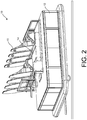
- Figure 3 shows the AGV from the back.
- the AGV needs to follow accurately a track in parallel to the power rail 30 and as such, a guiding rail 40 may be provided that is fixed to the floor (not shown) of the installation.
- the AGV has corresponding guide rollers 26 which engage with the guide rail, as indicated by arrow 42.
- the guide rail 40 and the guide rollers 26 force the AGV to follow the charging path C and to avoid any bad contacts between the contacts 24 of the AGV and the contacts of the power rail 30.
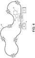
- FIG 4 shows a schematic view of a travel path, generally designated for the AGV 10.
- the travel path 50 has a start point A and an end point B and extends in a sinuous manner between the start and endpoints A, B.
- the travel path 50 is in the form of a closed loop such that the AGVs circulate around the travel path 50.
- the start point A may be defined by the passenger embarkation point A of the path 50, whereas the end point B may be defined by the passenger disembarkation point of the path 50.
- the travel path 50 may be defined in the themed environment by a guidance wire which is embedded in the floor of the environment.
- a transmitter is connected to the wire such that a radio signal of a predetermined frequency is broadcast from the wire.
- the AGV 10 is provided with an appropriate sensor which is able to detect the radio signal. Markers are typically provided in the floor to assist the AGV 10 in determining its position on the travel path 50.
- the travel path 50 may be a virtual path, defined only in software, as a set of time-based coordinate positions.
- the AGV follows this pre-programmed path, using its guidance system 18 to periodically correct its position.
- a return path 52 which closes the travel path 50 and the return path 52 to a closed loop.
- the system may have a dedicated charging path that is separate to the return path 52 allowing AGV to directly go from the end point B to the start point A without using the charging station 36.
- the AGV 10 is configured to travel for the majority of the path 50 between start point A and end point B at a steady rate. At predetermined points along the travel path 50 the AGV 10 may undertake a dynamic movement operation.
- Such dynamic movement operations include, for example, lateral translation movements, spins, helical spins, slides in or contrary to the direction of movement of the vehicle, periods of rapid acceleration and deceleration, transitions into reverse, sharp turns or combinations of the foregoing.
- the AGV is configured to operate in a stand-by mode.
- the autonomous guided vehicle enters in a different mode of operation, one where it does not carry passengers and preferably operates at a lower speed so as to reduce energy consumption or shorter motion cycle so as to reduce the charging cycle times.
- the stand-by mode defines a different mode of operation for the AGV.
- a system for autonomously monitoring the power and cell balancing of an AGV whilst operating in a stand-by mode An AGV operating in stand-by mode is able to operate automatically whilst unattended.
- the system is configured to monitor certain aspects of an AGV whilst the AGV is operating in stand-by mode.
- the system monitors the power and cell balancing of an AGV overnight.
- the system may monitor the power and cell balancing of an AGV during a period of low activity or low demand.
- the system is configured to monitor the power and cell balancing of a plurality of AGVs.
- the system is configured to monitor the power and cell balancing of an AGV such that, when the power module energy level of the AGV approaches a critical level, the balancing function performed by the system can be inhibited for the AGV.
- the critical level is a pre-determined value which is the same for every AGV.
- the critical level can be automatically determined by the system based on information collected from the AGV regarding the cell's prior usage and performance.
- the system is configured in either attended or unattended modes to demand that an AGV enter a charge cycle.
- the system demands that an AGV enter a charge cycle when the power module energy level indicates that charge is required.
- the system may demand that an AGV enter a charge cycle at a specific point in time and for a pre-defined period of time.
- the monitoring and control of the power and cell balancing of an AGV is performed by a module of the system.
- the module is implemented in software.
- the module may be implemented in hardware, or in a combination of hardware and software.
Landscapes
- Engineering & Computer Science (AREA)
- Power Engineering (AREA)
- Transportation (AREA)
- Mechanical Engineering (AREA)
- Aviation & Aerospace Engineering (AREA)
- Radar, Positioning & Navigation (AREA)
- Remote Sensing (AREA)
- Physics & Mathematics (AREA)
- General Physics & Mathematics (AREA)
- Automation & Control Theory (AREA)
- Electric Propulsion And Braking For Vehicles (AREA)
- Charge And Discharge Circuits For Batteries Or The Like (AREA)
Claims (15)
- System zum Befördern eines Fahrgastes in einem automatisiert geführten Fahrzeug (10), das für Unterhaltungszwecke verwendet wird, umfassend ein automatisiert geführtes Fahrzeug zum Befördern eines Fahrgastes und Führungsmittel, wobei das automatisiert geführte Fahrzeug (10) durch mindestens einen Elektromotor angetrieben wird, wobei das automatisiert geführte Fahrzeug (10) mindestens einen Kondensator (20) als Energiequelle (36) für den mindestens einen Elektromotor umfasst, wobei das automatisiert geführte Fahrzeug (10) derart betreibbar ist, dass es einem Weg über einen Boden von einem Startpunkt (A) zu einem Endpunkt (B) folgt, den das automatisiert geführte Fahrzeug (10) fahren soll, wobei das automatisiert geführte Fahrzeug (10) ferner derart betreibbar ist, dass es auf einem Rückweg von dem Endpunkt (B) zu dem Startpunkt (A) eine Ladestation (C) aufsucht, um den mindestens einen Kondensator (20) an der Ladestation (C) wieder aufzuladen, dadurch gekennzeichnet, dass die Ladestation (C) einen Teil des Weges von dem Endpunkt (B) zu dem Startpunkt (A) bildet und wobei das automatisiert geführte Fahrzeug über eine Stromschiene (30) geladen wird.
- System zum Befördern eines Fahrgastes in einem automatisiert geführten Fahrzeug nach Anspruch 1, wobei das den Fahrgast befördernde, automatisiert geführte Fahrzeug weiterhin ein Lademodul zum Laden des mindestens einen Kondensators umfasst.
- System zum Befördern eines Fahrgastes in einem automatisiert geführten Fahrzeug nach Anspruch 2, wobei das den Fahrgast befördernde, automatisiert geführte Fahrzeug ferner Ladekontakte zur elektrischen Kontaktierung mit einer externen Ladestation umfasst, insbesondere wobei die Ladekontakte als Schleifkontakte zur Kontaktierung mit einer Ladeschiene ausgebildet sind, oder alternativ, wobei das den Fahrgast befördernde, automatisiert geführte Fahrzeug ferner kontaktlose Lademittel zur kontaktlosen Übertragung von Energie von einer externen Ladestation umfasst.
- System zum Befördern eines Fahrgastes in einem automatisiert geführten Fahrzeug nach einem der Ansprüche 1 bis 3, wobei der mindestens eine Kondensator auf im Wesentlichen 690 Volt aufgeladen wird, insbesondere wobei der mindestens eine Elektromotor ein für eine Nennspannung von im Wesentlichen 400 Volt spezifizierter Motor ist, insbesondere wobei der Kondensator die Gleichspannungseingänge (DC-Bus) der Motorsteuerung direkt mit Energie versorgt.
- System zum Befördern eines Fahrgastes in einem automatisiert geführten Fahrzeug nach einem der Ansprüche 1 bis 4, wobei das automatisiert geführte Fahrzeug ferner einen Konverter zur Umwandlung der von dem mindestens einen Kondensator gelieferten elektrischen Energie umfasst, um den Elektromotor mit dem Niveau der elektrischen Energie in Abhängigkeit von der aktuellen Spannung des mindestens einen Kondensators und dem Energiebedarf des Elektromotors zu versorgen, um eine vorgeschriebene Geschwindigkeit und ein entsprechendes Drehmoment zu liefern.
- System zum Befördern eines Fahrgastes in einem automatisiert geführten Fahrzeug nach einem der Ansprüche 1 bis 5, wobei sich der mindestens eine Kondensator in einer entnehmbaren Baugruppe befindet, insbesondere wobei die entnehmbare Baugruppe als ein kondensatorbasiertes Leistungsmodul ausgeführt ist, das in ein abgedichtetes Gehäuse eingebaut und als austauschbare Kassette ausgebildet ist.
- System zum Befördern eines Fahrgastes in einem automatisiert geführten Fahrzeug nach Anspruch 1, wobei das automatisiert geführte Fahrzeug ein Lademodul zum Messen einer verbleibenden Kapazität des Kondensators umfasst, die gemessene Kapazität mit einem vordefinierten Wert vergleicht, der die minimale Kapazität angibt, die ein automatisiert geführtes Fahrzeug benötigt, um mindestens eine Tour vom Startpunkt (A) zum Endpunkt (B) und vom Endpunkt (B) zu einer Ladestation (C) zu absolvieren, und, wenn das Ladesteuermodul feststellt, dass die gemessene verbleibende Kapazität unter der vordefinierten Kapazität liegt, das Ladekontrollmodul eine Aktion einleitet, durch die das automatisiert geführte Fahrzeug zu einer Ladestation (C) geführt wird.
- System zum Befördern eines Fahrgastes in einem automatisiert geführten Fahrzeug nach einem der Ansprüche 1 bis 7, wobei der Motor regenerative Bremsströme direkt in den Kondensator zurück einspeist.
- System zum Befördern eines Fahrgastes in einem automatisiert geführten Fahrzeug nach einem der Ansprüche 1 bis 8, wobei das automatisiert geführte Fahrzeug ferner eine oder mehrere Sicherheitstrenneinheiten umfasst, die so konfiguriert sind, dass sie den Kondensator sowohl von einem Eingang des Ladesystems als auch von einem Gleichstrom-Datenbusausgang der Motorsteuerung trennen.
- System zum Befördern eines Fahrgastes in einem automatisiert geführten Fahrzeug nach einem der Ansprüche 1 bis 9, umfassend einen Leistungsmodul auf Kondensatorbasis, wobei dieses Leistungsmodul eine Serienlast zur Begrenzung des Einschaltstroms zu den Motorsteuerungen aufweist und/oder mit einem Entladewiderstand für die Restleistung der Motorsteuerungen zum Abbauen der Motorleistung versehen ist.
- System zum Befördern eines Fahrgastes in einem automatisiert geführten Fahrzeug nach einem der Ansprüche 1 bis 9, wobei das automatisiert geführte Fahrzeug ein kondensatorbasiertes Leistungsmodul umfasst, welches ein integriertes Schaltnetzteil enthält, das Hochspannung auf Niederspannung für Steuer- und Sicherheitsüberwachungsfunktionen und Energie umwandelt, wobei das automatisiert geführte Fahrzeug ferner eine unterbrechungsfreie Stromversorgung (USV) zur Bereitstellung von Reservestrom für die Sicherheits- und Steuerfunktionalität im Falle eines Ausfalls des Schaltnetzteils umfasst, wobei die unterbrechungsfreie Stromversorgung vorzugsweise durch das integrierte Schaltnetzteil mit der Niederspannung geladen wird.
- System zum Befördern eines Fahrgastes in einem automatisiert geführten Fahrzeug nach einem der Ansprüche 3 bis 11, ferner umfassend eine Ladestation mit bereitgestellten Kontakten, die den Ladekontakten des automatisiert geführten Fahrzeugs entsprechen, und/oder Mittel, die den kontaktlosen Lademitteln des automatisiert geführten Fahrzeugs entsprechen.
- Verfahren zum Betreiben eines Systems zum Befördern eines Fahrgastes in einem automatisiert geführten Fahrzeug, umfassend die folgenden Schritte:Versehen des zum Befördern eines Fahrgastes dienenden, automatisiert geführten Fahrzeugs mit einem Kondensator als Quelle für elektrische Energie;Laden des Kondensators des zum Befördern eines Fahrgastes dienenden, automatisiert geführten Fahrzeugs mit elektrischer Energie;Verwenden der in dem Kondensator gespeicherten elektrischen Energie zur Versorgung von Elektromotoren des zum Befördern eines Fahrgastes dienenden, automatisiert geführten Fahrzeugs;Führen des zum Befördern eines Fahrgastes dienenden, automatisiert geführten Fahrzeugs entlang eines definierten Fahrwegs von einem Startpunkt (A) zu einem Endpunkt (B);Führen des zum Befördern eines Fahrgastes dienenden, automatisiert geführten Fahrzeugs von dem Endpunkt (B) zu einer Ladestation (C), dadurch gekennzeichnet, dass die Ladestation (C) einen Teil des Weges von dem Endpunkt (B) zu dem Startpunkt (A) bildet und den Kondensator des zum Befördern eines Fahrgastes dienenden, automatisiert geführten Fahrzeugs über eine Stromschiene wieder auflädt;Führen des zum Befördern eines Fahrgastes dienenden, automatisiert geführten Fahrzeugs von der Ladestation (C) zu dem Startpunkt (A).
- Verfahren zum Betreiben eines Systems zum Befördern eines Fahrgastes in einem automatisiert geführten Fahrzeug nach Anspruch 13 und ferner umfassend die folgenden Schritte:Messen der Restkapazität des Kondensators des zum Befördern eines Fahrgastes dienenden, automatisiert geführten Fahrzeugs;Vergleichen der gemessenen Restkapazität des zum Befördern eines Fahrgastes dienenden, automatisiert geführten Fahrzeugs mit einem vordefinierten Wert;für den Fall, dass die gemessene Restkapazität des Kondensators des zum Befördern eines Fahrgastes dienenden, automatisiert geführten Fahrzeugs unter dem vordefinierten Schwellenwert liegt, soll das zum Befördern eines Fahrgastes dienende, automatisiert geführte Fahrzeug veranlasst werden, zu einer Ladestation zu fahren, um den Kondensator des zum Befördern eines Fahrgastes dienenden, automatisiert geführten Fahrzeugs wieder aufzuladen;Bereitstellen eines Kabels zum Senden von Funksignalen zu definierten Grenzwerten, wobei das Kabel in eine Fläche eingebettet ist, über die das zum Befördern eines Fahrgastes dienende, automatisiert geführte Fahrzeug fahren soll;Betreiben des zum Befördern eines Fahrgastes dienenden, automatisiert geführten Fahrzeugs in der Weise, dass es einem beabsichtigten Fahrweg folgt; undVeranlassen der Sicherheitssteuerung, das Fahrzeug für den Fall anzuhalten, dass der periphere Sensor ausfällt, um das von dem Kabel gesendete Funksignal zu definierten Grenzwerten zu erfassen.
- Verfahren zum Betreiben eines Systems zum Befördern eines Fahrgastes in einem automatisiert geführten Fahrzeug nach Anspruch 13 oder 14, das ferner die folgenden Schritte umfasst:Messen der verbleibenden Kapazität des Kondensators des zum Befördern eines Fahrgastes dienenden, automatisiert geführten Fahrzeugs;Vergleichen der gemessenen Restkapazität des zum Befördern eines Fahrgastes dienenden, automatisiert geführten Fahrzeugs mit einem vordefinierten Wert;für den Fall, dass die gemessene Restkapazität des Kondensators des zum Befördern eines Fahrgastes dienenden, automatisiert geführten Fahrzeugs unter dem vordefinierten Schwellenwert liegt, Veranlassen des zum Befördern eines Fahrgastes dienenden, automatisiert geführten Fahrzeugs zu einer Ladestation zu fahren, um den Kondensator des zum Befördern eines Fahrgastes dienenden, automatisiert geführten Fahrzeugs wieder aufzuladen;Bereitstellen eines drahtlosen Funksignals, das Echtzeit-Sicherheitsinformationen von einer Master-Steuerung und einem optisch basierten sicherheits- und sichtbasierten Navigationssystem sendet;Betreiben des zum Befördern eines Fahrgastes dienenden, automatisiert geführten Fahrzeugs, so dass es einem vorgegebenen Fahrweg folgt; undVeranlassen der Sicherheitssteuerung, das Fahrzeug für den Fall anzuhalten, dass der periphere Sensor ausfällt, um das von der Master-Stationssteuerung gesendete drahtlose Funksignal zu erfassen, oder dass ein Hindernis oder ein Fehler in dem optisch basierten, sicherheits- und sichtbasierten Navigationssystem auftritt.
Applications Claiming Priority (2)
| Application Number | Priority Date | Filing Date | Title |
|---|---|---|---|
| GBGB1712256.5A GB201712256D0 (en) | 2017-07-31 | 2017-07-31 | Automated guided vehicles |
| PCT/GB2018/052187 WO2019025787A1 (en) | 2017-07-31 | 2018-07-31 | AUTOMATIC GUIDE VEHICLE |
Publications (2)
| Publication Number | Publication Date |
|---|---|
| EP3661616A1 EP3661616A1 (de) | 2020-06-10 |
| EP3661616B1 true EP3661616B1 (de) | 2021-09-22 |
Family
ID=59779012
Family Applications (1)
| Application Number | Title | Priority Date | Filing Date |
|---|---|---|---|
| EP18756478.6A Active EP3661616B1 (de) | 2017-07-31 | 2018-07-31 | Automatisierte geführte fahrzeuge |
Country Status (5)
| Country | Link |
|---|---|
| US (1) | US11612824B2 (de) |
| EP (1) | EP3661616B1 (de) |
| CN (1) | CN111344047B (de) |
| GB (2) | GB201712256D0 (de) |
| WO (1) | WO2019025787A1 (de) |
Families Citing this family (10)
| Publication number | Priority date | Publication date | Assignee | Title |
|---|---|---|---|---|
| US11267653B2 (en) * | 2019-10-07 | 2022-03-08 | Google Llc | Modular multifunctional workcells for autonomous guided vehicle applications |
| CN111106651A (zh) * | 2020-01-07 | 2020-05-05 | 无锡立赫智能科技有限公司 | 一种电容常温充电设备及电容常温充电方法 |
| CN111888774B (zh) * | 2020-07-03 | 2021-11-30 | 深圳怡丰自动化科技有限公司 | 一种座舱的控制方法和控制装置以及存储介质 |
| JP7297151B2 (ja) * | 2020-07-03 | 2023-06-23 | 深▲せん▼怡豊自動化科技有限公司 | Agv娯楽運輸工具及び接続組立体 |
| US12257915B2 (en) * | 2020-12-29 | 2025-03-25 | Abb Schweiz Ag | Charging of an AGV |
| CN112904857A (zh) * | 2021-01-20 | 2021-06-04 | 广东顺德工业设计研究院(广东顺德创新设计研究院) | 自动引导车控制方法、装置及自动引导车 |
| CN114326608B (zh) * | 2021-11-30 | 2024-05-31 | 云南昆船智能装备有限公司 | 一种基于多智能体的agv群系统 |
| CN114475306B (zh) * | 2021-12-29 | 2024-06-18 | 北京昊瑞昌科技有限公司 | 一种agv小车的充电方法 |
| CN115635985A (zh) * | 2022-10-21 | 2023-01-24 | 上海风语筑文化科技股份有限公司 | 轨道车 |
| CN117141263B (zh) * | 2023-11-01 | 2024-01-16 | 宁波舜宇贝尔机器人有限公司 | 一种agv小车充电控制方法、系统、智能终端及存储介质 |
Family Cites Families (15)
| Publication number | Priority date | Publication date | Assignee | Title |
|---|---|---|---|---|
| US5839554A (en) * | 1993-05-03 | 1998-11-24 | Auckland Uniservices Limited | Power collector for inductive power transfer |
| US5403238A (en) | 1993-08-19 | 1995-04-04 | The Walt Disney Company | Amusement park attraction |
| WO2008144752A2 (en) * | 2007-05-21 | 2008-11-27 | Nmhg Oregon, Llc | Energy recapture for an industrial vehicle |
| JP4539887B2 (ja) * | 2008-01-31 | 2010-09-08 | トヨタ自動車株式会社 | 搬送用自走車の充電管理方法及びシステム |
| EP2280773B1 (de) * | 2008-03-26 | 2018-02-21 | Vekoma Rides Engineering B.V. | Fahrgeschäft und antriebsverfahren zum antrieb einer fahrgasttransportvorrichtung eines solchen fahrgeschäfts |
| US7890228B2 (en) | 2008-12-01 | 2011-02-15 | Savant Automation, Inc. | Power source monitoring system for AGVs and method |
| EP2770394B1 (de) * | 2009-01-17 | 2019-08-07 | Boomerang Systems, Inc. | Automatisiertes Lagersystem |
| GB201220401D0 (en) | 2012-11-13 | 2012-12-26 | Robocoaster Ltd | Trackless manipulator |
| GB201309488D0 (en) * | 2013-05-28 | 2013-07-10 | Robocoaster Ltd | Improvements in or relating to automated guided vehicles |
| WO2015051190A2 (en) | 2013-10-02 | 2015-04-09 | Velocity Magnetics, Inc. | Solid state energy storage and management system |
| GB201320319D0 (en) * | 2013-11-18 | 2014-01-01 | Robocoaster Ltd | Movable screen |
| SE1550448A1 (en) | 2015-04-14 | 2016-10-15 | Texo Application Ab | Automatic storage facility vehicles |
| US9610510B2 (en) * | 2015-07-21 | 2017-04-04 | Disney Enterprises, Inc. | Sensing and managing vehicle behavior based on occupant awareness |
| CN105641928A (zh) * | 2016-04-06 | 2016-06-08 | 深圳星火互娱数字科技有限公司 | 一种动感车 |
| CN205706348U (zh) * | 2016-07-07 | 2016-11-23 | 力姆泰克(北京)传动设备股份有限公司 | 一种用于影院的多向观影车 |
-
2017
- 2017-07-31 GB GBGB1712256.5A patent/GB201712256D0/en not_active Ceased
-
2018
- 2018-07-31 GB GB2001520.2A patent/GB2579296A/en not_active Withdrawn
- 2018-07-31 WO PCT/GB2018/052187 patent/WO2019025787A1/en not_active Ceased
- 2018-07-31 CN CN201880050554.9A patent/CN111344047B/zh active Active
- 2018-07-31 EP EP18756478.6A patent/EP3661616B1/de active Active
- 2018-07-31 US US16/634,782 patent/US11612824B2/en active Active
Also Published As
| Publication number | Publication date |
|---|---|
| US11612824B2 (en) | 2023-03-28 |
| GB201712256D0 (en) | 2017-09-13 |
| WO2019025787A1 (en) | 2019-02-07 |
| US20200230508A1 (en) | 2020-07-23 |
| CN111344047A (zh) | 2020-06-26 |
| GB2579296A (en) | 2020-06-17 |
| EP3661616A1 (de) | 2020-06-10 |
| CN111344047B (zh) | 2022-06-07 |
| GB202001520D0 (en) | 2020-03-18 |
Similar Documents
| Publication | Publication Date | Title |
|---|---|---|
| EP3661616B1 (de) | Automatisierte geführte fahrzeuge | |
| RU2660182C2 (ru) | Электрическое транспортное средство и соответствующая транспортная система | |
| US10189679B2 (en) | Elevator car power supply | |
| US10500980B2 (en) | Modular battery pack system with series and parallel charging and propulsion modes | |
| US11904707B2 (en) | Rail transport vehicle electric energy storage and charging system | |
| CN106926718B (zh) | 用于对多个能量存储装置充电的方法和设备 | |
| EP2738034B1 (de) | Antriebssteuerungsvorrichtung für ein elektrofahrzeug | |
| EP3118080A1 (de) | Strassenbahnwagenantriebssystem und steuerungsverfahren dafür | |
| JP6603335B2 (ja) | 電源内蔵式鉄道輸送システム | |
| US20140239879A1 (en) | Battery charging system | |
| IL256072A (en) | An array consisting of an electric vehicle and a stationary charging system by inspiration; Related system, facility, vehicle and method | |
| JP2008253084A (ja) | ハイブリッド電源システム | |
| CN102785592A (zh) | 轨道车辆及其供电方法、站内供电系统、车载储能系统 | |
| CN111071057B (zh) | 磁悬浮列车及其牵引控制方法、系统 | |
| US20170166085A1 (en) | Railroad system | |
| WO2011158086A2 (en) | Electric power control apparatus and electric power control method for vehicle | |
| JP6753809B2 (ja) | 電源車用電気連結回路、電源車、編成車両用電気連結回路、編成車両、制御方法、バッテリモード切替方法、及び、架線モード切替方法 | |
| KR101281739B1 (ko) | 온라인 전기자동차의 배터리 충전 및 방전 제어 방법 및 장치 | |
| JP6148927B2 (ja) | 電車駆動システム | |
| CN113829899A (zh) | 一种列车、列车充电控制方法及设备 | |
| JP5742709B2 (ja) | 車両および車両の制御方法 | |
| CN113829928A (zh) | 一种列车、列车充电控制方法及设备 |
Legal Events
| Date | Code | Title | Description |
|---|---|---|---|
| STAA | Information on the status of an ep patent application or granted ep patent |
Free format text: STATUS: UNKNOWN |
|
| STAA | Information on the status of an ep patent application or granted ep patent |
Free format text: STATUS: THE INTERNATIONAL PUBLICATION HAS BEEN MADE |
|
| PUAI | Public reference made under article 153(3) epc to a published international application that has entered the european phase |
Free format text: ORIGINAL CODE: 0009012 |
|
| STAA | Information on the status of an ep patent application or granted ep patent |
Free format text: STATUS: REQUEST FOR EXAMINATION WAS MADE |
|
| 17P | Request for examination filed |
Effective date: 20200205 |
|
| AK | Designated contracting states |
Kind code of ref document: A1 Designated state(s): AL AT BE BG CH CY CZ DE DK EE ES FI FR GB GR HR HU IE IS IT LI LT LU LV MC MK MT NL NO PL PT RO RS SE SI SK SM TR |
|
| AX | Request for extension of the european patent |
Extension state: BA ME |
|
| DAV | Request for validation of the european patent (deleted) | ||
| DAX | Request for extension of the european patent (deleted) | ||
| GRAP | Despatch of communication of intention to grant a patent |
Free format text: ORIGINAL CODE: EPIDOSNIGR1 |
|
| STAA | Information on the status of an ep patent application or granted ep patent |
Free format text: STATUS: GRANT OF PATENT IS INTENDED |
|
| INTG | Intention to grant announced |
Effective date: 20210331 |
|
| GRAS | Grant fee paid |
Free format text: ORIGINAL CODE: EPIDOSNIGR3 |
|
| GRAA | (expected) grant |
Free format text: ORIGINAL CODE: 0009210 |
|
| STAA | Information on the status of an ep patent application or granted ep patent |
Free format text: STATUS: THE PATENT HAS BEEN GRANTED |
|
| AK | Designated contracting states |
Kind code of ref document: B1 Designated state(s): AL AT BE BG CH CY CZ DE DK EE ES FI FR GB GR HR HU IE IS IT LI LT LU LV MC MK MT NL NO PL PT RO RS SE SI SK SM TR |
|
| REG | Reference to a national code |
Ref country code: GB Ref legal event code: FG4D |
|
| REG | Reference to a national code |
Ref country code: DE Ref legal event code: R096 Ref document number: 602018023968 Country of ref document: DE |
|
| REG | Reference to a national code |
Ref country code: IE Ref legal event code: FG4D |
|
| REG | Reference to a national code |
Ref country code: CH Ref legal event code: EP Ref country code: AT Ref legal event code: REF Ref document number: 1431853 Country of ref document: AT Kind code of ref document: T Effective date: 20211015 |
|
| REG | Reference to a national code |
Ref country code: LT Ref legal event code: MG9D |
|
| REG | Reference to a national code |
Ref country code: NL Ref legal event code: MP Effective date: 20210922 |
|
| PG25 | Lapsed in a contracting state [announced via postgrant information from national office to epo] |
Ref country code: RS Free format text: LAPSE BECAUSE OF FAILURE TO SUBMIT A TRANSLATION OF THE DESCRIPTION OR TO PAY THE FEE WITHIN THE PRESCRIBED TIME-LIMIT Effective date: 20210922 Ref country code: SE Free format text: LAPSE BECAUSE OF FAILURE TO SUBMIT A TRANSLATION OF THE DESCRIPTION OR TO PAY THE FEE WITHIN THE PRESCRIBED TIME-LIMIT Effective date: 20210922 Ref country code: HR Free format text: LAPSE BECAUSE OF FAILURE TO SUBMIT A TRANSLATION OF THE DESCRIPTION OR TO PAY THE FEE WITHIN THE PRESCRIBED TIME-LIMIT Effective date: 20210922 Ref country code: FI Free format text: LAPSE BECAUSE OF FAILURE TO SUBMIT A TRANSLATION OF THE DESCRIPTION OR TO PAY THE FEE WITHIN THE PRESCRIBED TIME-LIMIT Effective date: 20210922 Ref country code: LT Free format text: LAPSE BECAUSE OF FAILURE TO SUBMIT A TRANSLATION OF THE DESCRIPTION OR TO PAY THE FEE WITHIN THE PRESCRIBED TIME-LIMIT Effective date: 20210922 Ref country code: BG Free format text: LAPSE BECAUSE OF FAILURE TO SUBMIT A TRANSLATION OF THE DESCRIPTION OR TO PAY THE FEE WITHIN THE PRESCRIBED TIME-LIMIT Effective date: 20211222 Ref country code: NO Free format text: LAPSE BECAUSE OF FAILURE TO SUBMIT A TRANSLATION OF THE DESCRIPTION OR TO PAY THE FEE WITHIN THE PRESCRIBED TIME-LIMIT Effective date: 20211222 |
|
| REG | Reference to a national code |
Ref country code: AT Ref legal event code: MK05 Ref document number: 1431853 Country of ref document: AT Kind code of ref document: T Effective date: 20210922 |
|
| PG25 | Lapsed in a contracting state [announced via postgrant information from national office to epo] |
Ref country code: LV Free format text: LAPSE BECAUSE OF FAILURE TO SUBMIT A TRANSLATION OF THE DESCRIPTION OR TO PAY THE FEE WITHIN THE PRESCRIBED TIME-LIMIT Effective date: 20210922 Ref country code: GR Free format text: LAPSE BECAUSE OF FAILURE TO SUBMIT A TRANSLATION OF THE DESCRIPTION OR TO PAY THE FEE WITHIN THE PRESCRIBED TIME-LIMIT Effective date: 20211223 |
|
| PG25 | Lapsed in a contracting state [announced via postgrant information from national office to epo] |
Ref country code: AT Free format text: LAPSE BECAUSE OF FAILURE TO SUBMIT A TRANSLATION OF THE DESCRIPTION OR TO PAY THE FEE WITHIN THE PRESCRIBED TIME-LIMIT Effective date: 20210922 |
|
| PG25 | Lapsed in a contracting state [announced via postgrant information from national office to epo] |
Ref country code: IS Free format text: LAPSE BECAUSE OF FAILURE TO SUBMIT A TRANSLATION OF THE DESCRIPTION OR TO PAY THE FEE WITHIN THE PRESCRIBED TIME-LIMIT Effective date: 20220122 Ref country code: SK Free format text: LAPSE BECAUSE OF FAILURE TO SUBMIT A TRANSLATION OF THE DESCRIPTION OR TO PAY THE FEE WITHIN THE PRESCRIBED TIME-LIMIT Effective date: 20210922 Ref country code: RO Free format text: LAPSE BECAUSE OF FAILURE TO SUBMIT A TRANSLATION OF THE DESCRIPTION OR TO PAY THE FEE WITHIN THE PRESCRIBED TIME-LIMIT Effective date: 20210922 Ref country code: PT Free format text: LAPSE BECAUSE OF FAILURE TO SUBMIT A TRANSLATION OF THE DESCRIPTION OR TO PAY THE FEE WITHIN THE PRESCRIBED TIME-LIMIT Effective date: 20220124 Ref country code: PL Free format text: LAPSE BECAUSE OF FAILURE TO SUBMIT A TRANSLATION OF THE DESCRIPTION OR TO PAY THE FEE WITHIN THE PRESCRIBED TIME-LIMIT Effective date: 20210922 Ref country code: NL Free format text: LAPSE BECAUSE OF FAILURE TO SUBMIT A TRANSLATION OF THE DESCRIPTION OR TO PAY THE FEE WITHIN THE PRESCRIBED TIME-LIMIT Effective date: 20210922 Ref country code: ES Free format text: LAPSE BECAUSE OF FAILURE TO SUBMIT A TRANSLATION OF THE DESCRIPTION OR TO PAY THE FEE WITHIN THE PRESCRIBED TIME-LIMIT Effective date: 20210922 Ref country code: EE Free format text: LAPSE BECAUSE OF FAILURE TO SUBMIT A TRANSLATION OF THE DESCRIPTION OR TO PAY THE FEE WITHIN THE PRESCRIBED TIME-LIMIT Effective date: 20210922 Ref country code: CZ Free format text: LAPSE BECAUSE OF FAILURE TO SUBMIT A TRANSLATION OF THE DESCRIPTION OR TO PAY THE FEE WITHIN THE PRESCRIBED TIME-LIMIT Effective date: 20210922 Ref country code: AL Free format text: LAPSE BECAUSE OF FAILURE TO SUBMIT A TRANSLATION OF THE DESCRIPTION OR TO PAY THE FEE WITHIN THE PRESCRIBED TIME-LIMIT Effective date: 20210922 |
|
| REG | Reference to a national code |
Ref country code: DE Ref legal event code: R097 Ref document number: 602018023968 Country of ref document: DE |
|
| PG25 | Lapsed in a contracting state [announced via postgrant information from national office to epo] |
Ref country code: DK Free format text: LAPSE BECAUSE OF FAILURE TO SUBMIT A TRANSLATION OF THE DESCRIPTION OR TO PAY THE FEE WITHIN THE PRESCRIBED TIME-LIMIT Effective date: 20210922 |
|
| PLBE | No opposition filed within time limit |
Free format text: ORIGINAL CODE: 0009261 |
|
| STAA | Information on the status of an ep patent application or granted ep patent |
Free format text: STATUS: NO OPPOSITION FILED WITHIN TIME LIMIT |
|
| 26N | No opposition filed |
Effective date: 20220623 |
|
| PG25 | Lapsed in a contracting state [announced via postgrant information from national office to epo] |
Ref country code: SI Free format text: LAPSE BECAUSE OF FAILURE TO SUBMIT A TRANSLATION OF THE DESCRIPTION OR TO PAY THE FEE WITHIN THE PRESCRIBED TIME-LIMIT Effective date: 20210922 |
|
| PG25 | Lapsed in a contracting state [announced via postgrant information from national office to epo] |
Ref country code: IT Free format text: LAPSE BECAUSE OF FAILURE TO SUBMIT A TRANSLATION OF THE DESCRIPTION OR TO PAY THE FEE WITHIN THE PRESCRIBED TIME-LIMIT Effective date: 20210922 |
|
| PG25 | Lapsed in a contracting state [announced via postgrant information from national office to epo] |
Ref country code: MC Free format text: LAPSE BECAUSE OF FAILURE TO SUBMIT A TRANSLATION OF THE DESCRIPTION OR TO PAY THE FEE WITHIN THE PRESCRIBED TIME-LIMIT Effective date: 20210922 |
|
| REG | Reference to a national code |
Ref country code: CH Ref legal event code: PL |
|
| REG | Reference to a national code |
Ref country code: BE Ref legal event code: MM Effective date: 20220731 |
|
| PG25 | Lapsed in a contracting state [announced via postgrant information from national office to epo] |
Ref country code: LU Free format text: LAPSE BECAUSE OF NON-PAYMENT OF DUE FEES Effective date: 20220731 Ref country code: LI Free format text: LAPSE BECAUSE OF NON-PAYMENT OF DUE FEES Effective date: 20220731 Ref country code: CH Free format text: LAPSE BECAUSE OF NON-PAYMENT OF DUE FEES Effective date: 20220731 |
|
| PG25 | Lapsed in a contracting state [announced via postgrant information from national office to epo] |
Ref country code: BE Free format text: LAPSE BECAUSE OF NON-PAYMENT OF DUE FEES Effective date: 20220731 |
|
| PG25 | Lapsed in a contracting state [announced via postgrant information from national office to epo] |
Ref country code: IE Free format text: LAPSE BECAUSE OF NON-PAYMENT OF DUE FEES Effective date: 20220731 |
|
| PG25 | Lapsed in a contracting state [announced via postgrant information from national office to epo] |
Ref country code: SM Free format text: LAPSE BECAUSE OF FAILURE TO SUBMIT A TRANSLATION OF THE DESCRIPTION OR TO PAY THE FEE WITHIN THE PRESCRIBED TIME-LIMIT Effective date: 20210922 Ref country code: MK Free format text: LAPSE BECAUSE OF FAILURE TO SUBMIT A TRANSLATION OF THE DESCRIPTION OR TO PAY THE FEE WITHIN THE PRESCRIBED TIME-LIMIT Effective date: 20210922 Ref country code: CY Free format text: LAPSE BECAUSE OF FAILURE TO SUBMIT A TRANSLATION OF THE DESCRIPTION OR TO PAY THE FEE WITHIN THE PRESCRIBED TIME-LIMIT Effective date: 20210922 |
|
| PG25 | Lapsed in a contracting state [announced via postgrant information from national office to epo] |
Ref country code: HU Free format text: LAPSE BECAUSE OF FAILURE TO SUBMIT A TRANSLATION OF THE DESCRIPTION OR TO PAY THE FEE WITHIN THE PRESCRIBED TIME-LIMIT; INVALID AB INITIO Effective date: 20180731 |
|
| PG25 | Lapsed in a contracting state [announced via postgrant information from national office to epo] |
Ref country code: TR Free format text: LAPSE BECAUSE OF FAILURE TO SUBMIT A TRANSLATION OF THE DESCRIPTION OR TO PAY THE FEE WITHIN THE PRESCRIBED TIME-LIMIT Effective date: 20210922 |
|
| PG25 | Lapsed in a contracting state [announced via postgrant information from national office to epo] |
Ref country code: MT Free format text: LAPSE BECAUSE OF FAILURE TO SUBMIT A TRANSLATION OF THE DESCRIPTION OR TO PAY THE FEE WITHIN THE PRESCRIBED TIME-LIMIT Effective date: 20210922 |
|
| PGFP | Annual fee paid to national office [announced via postgrant information from national office to epo] |
Ref country code: DE Payment date: 20250722 Year of fee payment: 8 |
|
| PGFP | Annual fee paid to national office [announced via postgrant information from national office to epo] |
Ref country code: GB Payment date: 20250716 Year of fee payment: 8 |
|
| PGFP | Annual fee paid to national office [announced via postgrant information from national office to epo] |
Ref country code: FR Payment date: 20250725 Year of fee payment: 8 |