EP3661409B1 - Ballonnet gonflable a usage médical - Google Patents
Ballonnet gonflable a usage médical Download PDFInfo
- Publication number
- EP3661409B1 EP3661409B1 EP18762573.6A EP18762573A EP3661409B1 EP 3661409 B1 EP3661409 B1 EP 3661409B1 EP 18762573 A EP18762573 A EP 18762573A EP 3661409 B1 EP3661409 B1 EP 3661409B1
- Authority
- EP
- European Patent Office
- Prior art keywords
- balloon
- medical use
- wall
- inflatable balloon
- use according
- Prior art date
- Legal status (The legal status is an assumption and is not a legal conclusion. Google has not performed a legal analysis and makes no representation as to the accuracy of the status listed.)
- Active
Links
Images

Classifications
-
- A—HUMAN NECESSITIES
- A61—MEDICAL OR VETERINARY SCIENCE; HYGIENE
- A61B—DIAGNOSIS; SURGERY; IDENTIFICATION
- A61B5/00—Measuring for diagnostic purposes; Identification of persons
- A61B5/68—Arrangements of detecting, measuring or recording means, e.g. sensors, in relation to patient
- A61B5/6801—Arrangements of detecting, measuring or recording means, e.g. sensors, in relation to patient specially adapted to be attached to or worn on the body surface
- A61B5/6813—Specially adapted to be attached to a specific body part
- A61B5/6814—Head
- A61B5/6819—Nose
-
- A—HUMAN NECESSITIES
- A61—MEDICAL OR VETERINARY SCIENCE; HYGIENE
- A61B—DIAGNOSIS; SURGERY; IDENTIFICATION
- A61B17/00—Surgical instruments, devices or methods
- A61B17/22—Implements for squeezing-off ulcers or the like on inner organs of the body; Implements for scraping-out cavities of body organs, e.g. bones; for invasive removal or destruction of calculus using mechanical vibrations; for removing obstructions in blood vessels, not otherwise provided for
-
- A—HUMAN NECESSITIES
- A61—MEDICAL OR VETERINARY SCIENCE; HYGIENE
- A61B—DIAGNOSIS; SURGERY; IDENTIFICATION
- A61B17/00—Surgical instruments, devices or methods
- A61B17/12—Surgical instruments, devices or methods for ligaturing or otherwise compressing tubular parts of the body, e.g. blood vessels or umbilical cord
- A61B17/12022—Occluding by internal devices, e.g. balloons or releasable wires
- A61B17/12099—Occluding by internal devices, e.g. balloons or releasable wires characterised by the location of the occluder
- A61B17/12104—Occluding by internal devices, e.g. balloons or releasable wires characterised by the location of the occluder in an air passage
-
- A—HUMAN NECESSITIES
- A61—MEDICAL OR VETERINARY SCIENCE; HYGIENE
- A61B—DIAGNOSIS; SURGERY; IDENTIFICATION
- A61B17/00—Surgical instruments, devices or methods
- A61B17/12—Surgical instruments, devices or methods for ligaturing or otherwise compressing tubular parts of the body, e.g. blood vessels or umbilical cord
- A61B17/12022—Occluding by internal devices, e.g. balloons or releasable wires
- A61B17/12131—Occluding by internal devices, e.g. balloons or releasable wires characterised by the type of occluding device
- A61B17/12136—Balloons
-
- A—HUMAN NECESSITIES
- A61—MEDICAL OR VETERINARY SCIENCE; HYGIENE
- A61B—DIAGNOSIS; SURGERY; IDENTIFICATION
- A61B5/00—Measuring for diagnostic purposes; Identification of persons
- A61B5/0059—Measuring for diagnostic purposes; Identification of persons using light, e.g. diagnosis by transillumination, diascopy, fluorescence
- A61B5/0075—Measuring for diagnostic purposes; Identification of persons using light, e.g. diagnosis by transillumination, diascopy, fluorescence by spectroscopy, i.e. measuring spectra, e.g. Raman spectroscopy, infrared absorption spectroscopy
-
- A—HUMAN NECESSITIES
- A61—MEDICAL OR VETERINARY SCIENCE; HYGIENE
- A61B—DIAGNOSIS; SURGERY; IDENTIFICATION
- A61B5/00—Measuring for diagnostic purposes; Identification of persons
- A61B5/145—Measuring characteristics of blood in vivo, e.g. gas concentration or pH-value ; Measuring characteristics of body fluids or tissues, e.g. interstitial fluid or cerebral tissue
-
- A—HUMAN NECESSITIES
- A61—MEDICAL OR VETERINARY SCIENCE; HYGIENE
- A61B—DIAGNOSIS; SURGERY; IDENTIFICATION
- A61B5/00—Measuring for diagnostic purposes; Identification of persons
- A61B5/145—Measuring characteristics of blood in vivo, e.g. gas concentration or pH-value ; Measuring characteristics of body fluids or tissues, e.g. interstitial fluid or cerebral tissue
- A61B5/14532—Measuring characteristics of blood in vivo, e.g. gas concentration or pH-value ; Measuring characteristics of body fluids or tissues, e.g. interstitial fluid or cerebral tissue for measuring glucose, e.g. by tissue impedance measurement
-
- A—HUMAN NECESSITIES
- A61—MEDICAL OR VETERINARY SCIENCE; HYGIENE
- A61B—DIAGNOSIS; SURGERY; IDENTIFICATION
- A61B5/00—Measuring for diagnostic purposes; Identification of persons
- A61B5/145—Measuring characteristics of blood in vivo, e.g. gas concentration or pH-value ; Measuring characteristics of body fluids or tissues, e.g. interstitial fluid or cerebral tissue
- A61B5/1455—Measuring characteristics of blood in vivo, e.g. gas concentration or pH-value ; Measuring characteristics of body fluids or tissues, e.g. interstitial fluid or cerebral tissue using optical sensors, e.g. spectral photometrical oximeters
- A61B5/14551—Measuring characteristics of blood in vivo, e.g. gas concentration or pH-value ; Measuring characteristics of body fluids or tissues, e.g. interstitial fluid or cerebral tissue using optical sensors, e.g. spectral photometrical oximeters for measuring blood gases
- A61B5/14552—Details of sensors specially adapted therefor
-
- A—HUMAN NECESSITIES
- A61—MEDICAL OR VETERINARY SCIENCE; HYGIENE
- A61B—DIAGNOSIS; SURGERY; IDENTIFICATION
- A61B5/00—Measuring for diagnostic purposes; Identification of persons
- A61B5/68—Arrangements of detecting, measuring or recording means, e.g. sensors, in relation to patient
- A61B5/6846—Arrangements of detecting, measuring or recording means, e.g. sensors, in relation to patient specially adapted to be brought in contact with an internal body part, i.e. invasive
- A61B5/6847—Arrangements of detecting, measuring or recording means, e.g. sensors, in relation to patient specially adapted to be brought in contact with an internal body part, i.e. invasive mounted on an invasive device
- A61B5/6852—Catheters
- A61B5/6853—Catheters with a balloon
-
- A—HUMAN NECESSITIES
- A61—MEDICAL OR VETERINARY SCIENCE; HYGIENE
- A61B—DIAGNOSIS; SURGERY; IDENTIFICATION
- A61B5/00—Measuring for diagnostic purposes; Identification of persons
- A61B5/74—Details of notification to user or communication with user or patient; User input means
-
- G—PHYSICS
- G16—INFORMATION AND COMMUNICATION TECHNOLOGY [ICT] SPECIALLY ADAPTED FOR SPECIFIC APPLICATION FIELDS
- G16H—HEALTHCARE INFORMATICS, i.e. INFORMATION AND COMMUNICATION TECHNOLOGY [ICT] SPECIALLY ADAPTED FOR THE HANDLING OR PROCESSING OF MEDICAL OR HEALTHCARE DATA
- G16H40/00—ICT specially adapted for the management or administration of healthcare resources or facilities; ICT specially adapted for the management or operation of medical equipment or devices
- G16H40/60—ICT specially adapted for the management or administration of healthcare resources or facilities; ICT specially adapted for the management or operation of medical equipment or devices for the operation of medical equipment or devices
- G16H40/67—ICT specially adapted for the management or administration of healthcare resources or facilities; ICT specially adapted for the management or operation of medical equipment or devices for the operation of medical equipment or devices for remote operation
-
- A—HUMAN NECESSITIES
- A61—MEDICAL OR VETERINARY SCIENCE; HYGIENE
- A61B—DIAGNOSIS; SURGERY; IDENTIFICATION
- A61B17/00—Surgical instruments, devices or methods
- A61B17/24—Surgical instruments, devices or methods for use in the oral cavity, larynx, bronchial passages or nose; Tongue scrapers
-
- A—HUMAN NECESSITIES
- A61—MEDICAL OR VETERINARY SCIENCE; HYGIENE
- A61B—DIAGNOSIS; SURGERY; IDENTIFICATION
- A61B17/00—Surgical instruments, devices or methods
- A61B2017/00017—Electrical control of surgical instruments
- A61B2017/00022—Sensing or detecting at the treatment site
-
- A—HUMAN NECESSITIES
- A61—MEDICAL OR VETERINARY SCIENCE; HYGIENE
- A61B—DIAGNOSIS; SURGERY; IDENTIFICATION
- A61B17/00—Surgical instruments, devices or methods
- A61B17/12—Surgical instruments, devices or methods for ligaturing or otherwise compressing tubular parts of the body, e.g. blood vessels or umbilical cord
- A61B2017/12004—Surgical instruments, devices or methods for ligaturing or otherwise compressing tubular parts of the body, e.g. blood vessels or umbilical cord for haemostasis, for prevention of bleeding
-
- A—HUMAN NECESSITIES
- A61—MEDICAL OR VETERINARY SCIENCE; HYGIENE
- A61B—DIAGNOSIS; SURGERY; IDENTIFICATION
- A61B17/00—Surgical instruments, devices or methods
- A61B17/22—Implements for squeezing-off ulcers or the like on inner organs of the body; Implements for scraping-out cavities of body organs, e.g. bones; for invasive removal or destruction of calculus using mechanical vibrations; for removing obstructions in blood vessels, not otherwise provided for
- A61B2017/22051—Implements for squeezing-off ulcers or the like on inner organs of the body; Implements for scraping-out cavities of body organs, e.g. bones; for invasive removal or destruction of calculus using mechanical vibrations; for removing obstructions in blood vessels, not otherwise provided for with an inflatable part, e.g. balloon, for positioning, blocking, or immobilisation
- A61B2017/22062—Implements for squeezing-off ulcers or the like on inner organs of the body; Implements for scraping-out cavities of body organs, e.g. bones; for invasive removal or destruction of calculus using mechanical vibrations; for removing obstructions in blood vessels, not otherwise provided for with an inflatable part, e.g. balloon, for positioning, blocking, or immobilisation to be filled with liquid
-
- A—HUMAN NECESSITIES
- A61—MEDICAL OR VETERINARY SCIENCE; HYGIENE
- A61B—DIAGNOSIS; SURGERY; IDENTIFICATION
- A61B2560/00—Constructional details of operational features of apparatus; Accessories for medical measuring apparatus
- A61B2560/04—Constructional details of apparatus
- A61B2560/0406—Constructional details of apparatus specially shaped apparatus housings
-
- A—HUMAN NECESSITIES
- A61—MEDICAL OR VETERINARY SCIENCE; HYGIENE
- A61B—DIAGNOSIS; SURGERY; IDENTIFICATION
- A61B2562/00—Details of sensors; Constructional details of sensor housings or probes; Accessories for sensors
- A61B2562/02—Details of sensors specially adapted for in-vivo measurements
-
- A—HUMAN NECESSITIES
- A61—MEDICAL OR VETERINARY SCIENCE; HYGIENE
- A61B—DIAGNOSIS; SURGERY; IDENTIFICATION
- A61B2562/00—Details of sensors; Constructional details of sensor housings or probes; Accessories for sensors
- A61B2562/16—Details of sensor housings or probes; Details of structural supports for sensors
- A61B2562/164—Details of sensor housings or probes; Details of structural supports for sensors the sensor is mounted in or on a conformable substrate or carrier
-
- A—HUMAN NECESSITIES
- A61—MEDICAL OR VETERINARY SCIENCE; HYGIENE
- A61B—DIAGNOSIS; SURGERY; IDENTIFICATION
- A61B2562/00—Details of sensors; Constructional details of sensor housings or probes; Accessories for sensors
- A61B2562/16—Details of sensor housings or probes; Details of structural supports for sensors
- A61B2562/166—Details of sensor housings or probes; Details of structural supports for sensors the sensor is mounted on a specially adapted printed circuit board
-
- A—HUMAN NECESSITIES
- A61—MEDICAL OR VETERINARY SCIENCE; HYGIENE
- A61B—DIAGNOSIS; SURGERY; IDENTIFICATION
- A61B2562/00—Details of sensors; Constructional details of sensor housings or probes; Accessories for sensors
- A61B2562/18—Shielding or protection of sensors from environmental influences, e.g. protection from mechanical damage
Definitions
- the present invention relates to an inflatable balloon for medical use, intended to be inserted deflated into a cavity of a human or animal body then inflated inside this cavity in order to press against the walls of this cavity.
- a balloon of this type is inserted into the nasal cavity of a patient, then inflated once correctly positioned using a fluid such as air, gelled water or serum. physiological.
- a fluid such as air, gelled water or serum. physiological.
- a common application of this type of balloon is the treatment of hemorrhages by pressure against the internal walls of the nasal cavity.
- the external sensor protrudes from the external face of the balloon body, so that the measuring device has reduced salience.
- a protective casing for the internal module since the latter is in a non-aggressive environment, generally air, gelled water or physiological serum.
- the external sensor transmits the electrical measurement signal to the internal module by means of one or more electrical wires passing in one or more conduits provided through the wall of the balloon body.
- a sealing material obstructs the conduit(s).
- the sealing material comprises glue fixing the sensor to the external face of the wall of the balloon body.
- the internal module is fixed on an internal face of the wall of the balloon body.
- the sealing material comprises glue fixing the internal module to the internal face of the wall of the balloon body.
- the internal module further comprises a wireless communication device designed to communicate the measurement of the biological quantity to a device located outside the human or animal body into which the inflatable balloon is inserted.
- the internal module also includes a memory for storing the measurement of the biological quantity.
- the external sensor is printed on the external face of the wall of the balloon body.
- the inflatable balloon for medical use is for use in otorhinolaryngology or neurosurgery and the balloon body is preformed to match the interior shapes of a nasal cavity of a human or animal body when inflated.
- the inflatable balloon 10 for medical use shown schematically on the figure 1 comprises a balloon body 12 whose wall 14 is made of flexible inflatable material, for example silicone or any equivalent material having these properties. It is intended to be inserted deflated into a human or animal body cavity, for example the nasal cavity, then inflated inside this cavity in order to press against it. It is of generally elongated shape, having a proximal end 16 for inflation and a distal end 18 for positioning at the bottom of the cavity.
- the exterior of the wall 14 is advantageously coated with a slippery product that is non-aggressive for the biological tissues of the cavity.
- the proximal end 16 comprises a rigid support 20 which has a first opening and an inflation tip 22 leading to this first opening.
- This tip 22 facilitates the introduction of a syringe to inflate the balloon body 12 under pressure using a fluid such as air, gelled water, physiological serum, or any other appropriate fluid .
- a fluid such as air, gelled water, physiological serum, or any other appropriate fluid .
- It may be fitted with a valve, or any suitable system for inflation, so as to allow injection or aspiration of fluid without there being any leaks when the syringe or the device is removed. inflation.
- the rigid support 20 also optionally presents a second opening 24 intended for the introduction of an endoscope into the balloon body 12.
- This second opening 24 is for example in the form of a valve or any system allowing the introduction of an endoscope while preventing any escape of fluid introduced into the balloon body 12.
- the fluid it is advantageous, even necessary, for the fluid to be as transparent or translucent as possible for better observation of the environment by the endoscope inside the balloon 10.
- the balloon 10 may further comprise an elongated sock 26 extending inside the balloon body 12 and having a closed distal end 28 not secured to the wall 14 of the balloon body 12.
- An elongated sock must be understood as an elongated cap, of complementary shape to that of the endoscope, inside which the second opening 24 opens. It allows the introduction of the endoscope without contact of the latter with the fluid present in the body balloon 12. It is advantageously formed from a flexible, possibly elastic material, for example silicone or any material of the same nature.
- the wall 14 of the balloon body 12 locally has an elongated portion 30, called the sole, of greater rigidity than the rest of the wall 14, this sole 30 extending from the proximal end 16 to the distal end 18 It forms the base of the balloon body 12, facilitating the introduction and maintenance of the balloon 10 in the desired cavity even when it is deflated. Furthermore, it fulfills a guide function during inflation of the balloon 10, giving it a pre-stressed direction.
- the sole 30 can be an attached part against the wall 14 of the balloon body 12, made of any material ensuring the desired rigidity function.
- This material can be chosen in a non-limiting manner from polymers such as polyvinyl chloride, polysiloxane, polyurethane, polyethylene polycarbonate, polymethyl methacrylate, polyethylene terephthalate, or among fluoropolymers such as polytetrafluoroethylene or polychlorotrifluoroethylene.
- it can be made integral with the rest of the wall 14 of the balloon body 12, but it then has a thickness significantly greater than the rest of this wall 14 to increase its rigidity.
- the inflatable balloon 10 also comprises one or more devices 31 for measuring in situ at least one biological quantity of the biological tissues of the nasal cavity and/or of the biological fluids present in the latter.
- the biological quantity includes, for example, a hemoglobin level, a protein level, a glucose level, a lactic acid level or a lactate level.
- the balloon 10 may also include one or more devices 33 for measuring the internal pressure of the balloon 10.
- the balloon 10 can be designed for use in otorhinolaryngology or neurosurgery.
- the wall 14 of the balloon body 12 can be preformed to match the interior shapes of a nasal cavity of a human or animal body in an inflated conformation.
- FIG. 3 illustrates the positioning of the balloon 10 of figures 1 and 2 in a nasal cavity 32, in deflated conformation. Thanks to the sole 30 having greater rigidity than the rest of the wall 14 of the balloon body 12, the balloon 10 is easily introduced into the nasal cavity 32. Once positioned, a fluid is introduced through the tip 22 into the balloon body 12 using a syringe 34. By doing this, the pressure inside the balloon body is easily controlled.
- the balloon 10 further comprises a rigid removable insertion rod 36 extending outwards in the extension of the tip 22.
- This rigid rod 36 makes it possible to facilitate the installation of the balloon 10 in the cavity and can be broken or removed when this installation is correctly carried out.
- the balloon 10 can be inflated using the syringe 34 before or after this maneuver.
- the balloon 10 of this other embodiment further comprises a removable rigid wire 38 for placement, extending to reinforce the sole 30 on along or in the latter.
- a removable rigid wire 38 for placement, extending to reinforce the sole 30 on along or in the latter. It is, for example, made of nickel-titanium alloy, this material having interesting shape memory and elasticity properties.
- the balloon 10 of this other embodiment comprises a reinforcement 40 at the distal end 18 in the extension of the sole 30.
- This distal reinforcement 40 has, like the sole 30, a rigidity greater than the rest of the wall 14 of the body of the sole.
- balloon 12 and is shaped, for example at an angle close to 90° relative to the sole 30, so as to prevent, in cooperation with the latter, any elongation of the balloon 10 during its inflation. It can concretely consist of a part attached to the distal end of the sole 30, made of any material ensuring the desired rigidity function.
- This material can be chosen in a non-limiting manner from polymers such as polyvinyl chloride, polysiloxane, polyurethane, polyethylene polycarbonate, polymethyl methacrylate, polyethylene terephthalate, or from fluoropolymers such as polytetrafluoroethylene or polychlorotrifluoroethylene.
- polymers such as polyvinyl chloride, polysiloxane, polyurethane, polyethylene polycarbonate, polymethyl methacrylate, polyethylene terephthalate, or from fluoropolymers such as polytetrafluoroethylene or polychlorotrifluoroethylene.
- the balloon 10 of this other embodiment is shown in deflated conformation on the Figure 5 and in inflated conformation, with removal of the rigid rod 36 and the removable rigid wire 38, on the Figure 6 .
- the measuring device 31 firstly comprises an external sensor 42 fixed on an external face 44 of the wall 14 of the balloon body 12 in order to come into contact with the biological tissues of the nasal cavity and/or the biological fluids present in the latter when the balloon 12 is inflated in the cavity.
- the external sensor 42 is designed to provide, spontaneously or in response to an electrical request, an electrical signal for sensitive measurement of the biological quantity measured.
- the electrical measurement signal is for example an analog signal, such as an electric current or an electric voltage.
- the external sensor 42 can have two electrodes.
- the latter provides an electrical signal in the form of an electric current depending on the glucose level in the biological tissues and/or in the biological fluids present between the electrodes.
- the external sensor 42 may include a radiation emitter electromagnetic (for example, light) intended to interact with a tissue mass and at least one receptor for the electromagnetic radiation having interacted with the tissue mass.
- the receiver may include, but is not limited to, one or more photodiodes.
- An example of a diffuse reflectance spectroscopy device is for example described in the American patent application published under the number US 2011/0105865 A1 .
- the external sensor 42 preferably has a thickness of less than 0.5 mm, more preferably less than 0.3 mm, in order to be as flush as possible with the wall 14 of the balloon body 12.
- the external sensor 42 may be a sensor printed on the external face 44 of the wall 14 of the balloon body 12. In this case, it generally has a thickness of between 0.1 and 0.3 mm. This type of sensor also has the advantage of resisting the deformation of the balloon body 12.
- the wall 14 of the balloon body 12 has locally, at the level of the external sensor 42, a portion 47, called reinforcement, of greater rigidity than the rest of the wall 14.
- the reinforcement 47 can be a piece attached against the wall 14 of the balloon body 12, made of any material ensuring the desired rigidity function.
- the reinforcement 47 can be made integral with the rest of the wall 14 of the balloon body 12, but it then has a thickness significantly greater than the rest of this wall 14 to increase its rigidity. The reinforcement 47 makes it possible to locally avoid excessive deformation of the balloon body 12 and therefore deterioration of the external sensor 42 during inflation of the balloon 10.
- the measuring device 31 further comprises an internal module 48 located in the balloon body 12 in order to be protected from biological fluids present in the nasal cavity.
- the internal module 48 is for example fixed on an internal face 50 of the wall 14 of the balloon body 12.
- the internal module 48 comprises a processing device 52 intended to receive and process the electrical measurement signal in order to provide successive measurements of the biological quantity, preferably in digital form.
- the processing device 52 comprises, for example, a printed circuit board.
- the processing device 52 can be designed to provide this request.
- the internal module 48 further includes a wireless communication device 54 designed to communicate the measurements to an external device, preferably a computing device, located outside the human or animal body into which the balloon 10 is inserted.
- the computing device is for example a smartphone, a tablet or a desktop computer.
- the internal module 48 may also include a memory 56 for storing the measurements, for example in order to read them once the balloon 10 has been extracted from the cavity.
- the electronic module 48 may also include a source of electrical energy 58, such as a chemical battery, to power its elements and in particular the processing device 52, the wireless communication device 54 and/or the memory 56.
- a source of electrical energy 58 such as a chemical battery
- the external sensor 42 transmits the electrical measurement signal to the internal module 48 by means of one or more electrical wires 60 passing in one or more conduits 62 provided through the wall 14 of the balloon body 12.
- the seal between the inside and the outside of the balloon 12 is ensured by means of a sealing material 64, such as a crosslinked gel, obstructing the conduit(s) 62.
- the sealing material 64 comprises for example glue allowing, in addition to its sealing function, the fixing of the sensor 42 to the external face 44 of the wall and/or the fixing of the internal module 48 to the internal face 50 of the wall 14.
- one or more radio-opaque markers 66 can be provided on the wall 14 of the balloon body 12, for example on its external face 44.
- a radio-opaque marker 66 is for example provided near each external sensor 42, for example less than a millimeter.
- the presence of the measuring device(s) 31 on the balloon body 12 thus allows remote monitoring of different biological parameters, knowledge of which is useful in otorhinolaryngology, neurosurgery or any other medical specialty.
- Dedicated software can be programmed to detect a deviation of the measurements from a normal range in which they should be.
- an automatic alert can be sent (for example by email or short telephone message (SMS)) to the healthcare professional so that he can warn, for example, the patient in whom the implant 10 is placed.
- the automatic alert can be sent directly to the patient, or to a call processing center which will be responsible for calling the healthcare professional and/or the patient.
- the measurements can be used by the healthcare professional to react to a potentially unforeseen event once the patient has left the hospital, or to make or refine their diagnosis, thus making it possible to personalize the treatment. of the patient.
- the measurements obtained can be used to constitute or populate registers or any other type of database.
- an inflatable balloon for medical use such as that described above makes it possible to obtain measurements of biological quantities, without their presence disrupting the flow of biological fluids or damaging biological tissues.
- It is particularly suitable for medical operations such as otorhinolaryngological, head and neck surgery or neurosurgery. It can also be used in other surgical operations, particularly in orthopedics or digestive surgery. Without even talking about surgery, it can also be used as a simple compression device to treat all kinds of epistaxis or bleeding from the nasal cavity, such bleeding commonly occurring in consultations, for example.
- the shapes of the sole 30 and the distal reinforcement 40 can be adapted to all the desired applications. They are therefore potentially very diverse.
Landscapes
- Health & Medical Sciences (AREA)
- Life Sciences & Earth Sciences (AREA)
- Surgery (AREA)
- Engineering & Computer Science (AREA)
- Biomedical Technology (AREA)
- Medical Informatics (AREA)
- Public Health (AREA)
- General Health & Medical Sciences (AREA)
- Veterinary Medicine (AREA)
- Heart & Thoracic Surgery (AREA)
- Molecular Biology (AREA)
- Animal Behavior & Ethology (AREA)
- Physics & Mathematics (AREA)
- Pathology (AREA)
- Biophysics (AREA)
- Nuclear Medicine, Radiotherapy & Molecular Imaging (AREA)
- Vascular Medicine (AREA)
- Reproductive Health (AREA)
- Otolaryngology (AREA)
- Optics & Photonics (AREA)
- Spectroscopy & Molecular Physics (AREA)
- Orthopedic Medicine & Surgery (AREA)
- Business, Economics & Management (AREA)
- General Business, Economics & Management (AREA)
- Epidemiology (AREA)
- Primary Health Care (AREA)
- Dentistry (AREA)
- Oral & Maxillofacial Surgery (AREA)
- Pulmonology (AREA)
- Emergency Medicine (AREA)
- Measuring And Recording Apparatus For Diagnosis (AREA)
- Measurement Of The Respiration, Hearing Ability, Form, And Blood Characteristics Of Living Organisms (AREA)
Description
- La présente invention concerne un ballonnet gonflable à usage médical, destiné à être inséré dégonflé dans une cavité de corps humain ou animal puis gonflé à l'intérieur de cette cavité en vue de faire pression contre les parois de cette cavité.
- En otorhinolaryngologie par exemple, un ballonnet de ce type est inséré dans la cavité nasale d'un patient, puis gonflé une fois correctement positionné à l'aide d'un fluide tel que de l'air, de l'eau gélifiée ou du sérum physiologique. Une application courante de ce type de ballonnet est le traitement d'hémorragies par pression contre les parois internes de la cavité nasale.
- L'invention s'applique plus particulièrement à un ballonnet à usage médical, destiné à être inséré dégonflé dans une cavité de corps humain ou animal puis gonflé à l'intérieur de cette cavité en vue de faire pression contre elle, comportant :
- un corps de ballonnet dont la paroi est en matériau souple gonflable,
- une ouverture de gonflage pour l'introduction d'un fluide dans le corps de ballonnet de manière à le gonfler sous pression, et
- au moins un dispositif de mesure d'une grandeur biologique de tissus biologiques de la cavité et/ou de fluides biologiques présents dans cette cavité.
- Ce type de ballonnet est par exemple décrit dans la demande de brevet internationale PCT publiée sous le numéro
WO 2016/067153 A1 . Dans cette publication, le dispositif de mesure est destiné à mesurer la saturation « pulsée » en oxygène, également appelée SpO2. - De manière générale, il peut être délicat de placer un dispositif de mesure sur la face externe d'un corps de ballonnet. En effet, le dispositif de mesure doit dépasser le moins possible afin de ne pas gêner l'écoulement des fluides dans la cavité et/ou de ne pas irriter les tissus biologiques de la cavité. Or, il est nécessaire de prévoir un boîtier pour protéger l'électronique du dispositif de mesure des agressions du milieu biologique de la cavité, comme cela est décrit par exemple dans la demande de brevet chinois publiée sous le numéro
CN 104055525 A . La présence de ce boîtier vient augmenter la taille du dispositif de mesure et augmente son encombrement, de sorte qu'il est difficile de réaliser un dispositif de mesure de faible saillance. Le documentUS 2012/0245553 A1 divulgue un ballonnet gonflable avec un contrôleur électronique couplé à la paroi du ballonnet et attenant à une valve configurée pour réguler l'administration au sujet du fluide contenu dans le ballonnet. - Il peut ainsi être souhaité de prévoir un ballonnet gonflable à usage médical qui permette de s'affranchir d'au moins une partie des problèmes et contraintes précités.
- Il est donc proposé un ballonnet à usage médical, destiné à être inséré dégonflé dans une cavité de corps humain ou animal puis gonflé à l'intérieur de cette cavité en vue de faire pression contre elle, comportant :
- un corps de ballonnet dont la paroi est en matériau souple gonflable,
- une ouverture de gonflage formée pour l'introduction d'un fluide dans le corps de ballonnet de manière à le gonfler sous pression, et
- au moins un dispositif de mesure d'une grandeur biologique de tissus biologiques de la cavité et/ou de fluides biologiques présents dans cette cavité,
- un capteur externe fixé sur une face externe de la paroi du corps de ballonnet et conçu pour fournir un signal électrique de mesure sensible à la grandeur biologique mesurée, et
- un module interne situé à l'intérieur du corps de ballonnet et comportant un dispositif de traitement conçu pour traiter le signal électrique de mesure afin de fournir au moins une mesure de la grandeur biologique.
- Ainsi, seul le capteur externe dépasse de la face externe du corps de ballonnet, de sorte que le dispositif de mesure présente une saillance réduite. En outre, il n'est plus nécessaire de prévoir un boîtier de protection du module interne, puisque ce dernier est dans un environnement non agressif, généralement de l'air, de l'eau gélifiée ou du sérum physiologique.
- De façon optionnelle, le capteur externe transmet le signal électrique de mesure au module interne au moyen d'un ou plusieurs fils électriques passant dans un ou des conduits ménagés au travers de la paroi du corps de ballonnet.
- De façon optionnelle également, un matériau d'étanchéité obstrue le ou les conduits.
- De façon optionnelle également, le matériau d'étanchéité comporte de la colle fixant le capteur à la face externe de la paroi du corps de ballonnet.
- De façon optionnelle également, le module interne est fixé sur une face interne de la paroi du corps de ballonnet.
- De façon optionnelle également, le matériau d'étanchéité comporte de la colle fixant le module interne à la face interne de la paroi du corps de ballonnet.
- De façon optionnelle également, le module interne comporte en outre un dispositif de communication sans fil conçu pour communiquer la mesure de la grandeur biologique à un dispositif situé à l'extérieur du corps humain ou animal dans lequel le ballonnet gonflable est inséré.
- De façon optionnelle également, le module interne comporte en outre une mémoire pour stocker la mesure de la grandeur biologique.
- De façon optionnelle également, le capteur externe est imprimé sur la face externe de la paroi du corps de ballonnet.
- De façon optionnelle également, le ballonnet gonflable à usage médical est à utilisation en otorhinolaryngologie ou en neurochirurgie et le corps de ballonnet est préformé pour épouser les formes intérieures d'une cavité nasale de corps humain ou animal lorsqu'il est gonflé.
- L'invention sera mieux comprise à l'aide de la description qui va suivre, donnée uniquement à titre d'exemple et faite en se référant aux dessins annexés dans lesquels :
- la
figure 1 représente schématiquement la structure générale d'un ballonnet gonflable à usage médical, selon un mode de réalisation de l'invention, - la
figure 2 illustre un exemple de forme pour le ballonnet de lafigure 1 , - les
figures 3 et 4 illustrent des dispositions du ballonnet de lafigure 1 dans une cavité nasale, avant et après gonflage, - les
figures 5 et 6 représentent schématiquement la structure générale d'un ballonnet gonflable à usage médical, selon un autre mode de réalisation de l'invention, avant et après gonflage, et - la
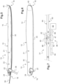
figure 7 représente schématiquement un dispositif de mesure d'une grandeur biologique, fixé à une paroi du ballonnet gonflable. - Le ballonnet gonflable 10 à usage médical représenté schématiquement sur la
figure 1 comporte un corps de ballonnet 12 dont la paroi 14 est en matériau souple gonflable, par exemple en silicone ou tout matériau équivalent présentant ces propriétés. Il est destiné à être inséré dégonflé dans une cavité de corps humain ou animal, par exemple la fosse nasale, puis gonflé à l'intérieur de cette cavité en vue de faire pression contre elle. Il est de forme générale allongée, présentant une extrémité proximale 16 de gonflage et une extrémité distale 18 de positionnement en fond de cavité. L'extérieur de la paroi 14 est avantageusement enduit d'un produit glissant et non agressif pour les tissus biologiques de la cavité. - L'extrémité proximale 16 comporte un support rigide 20 qui présente une première ouverture et un embout de gonflage 22 menant à cette première ouverture. Cet embout 22 facilite l'introduction d'une seringue pour gonfler le corps de ballonnet 12 sous pression à l'aide d'un fluide tel que de l'air, de l'eau gélifiée, du sérum physiologique, ou tout autre fluide approprié. Il peut être muni d'une valve, ou de tout système approprié pour le gonflage, de façon à permettre une injection ou une aspiration de fluide sans qu'il n'y ait de fuites lorsque l'on enlève la seringue ou le dispositif de gonflage.
- Le support rigide 20 présente en outre de façon optionnelle une seconde ouverture 24 destinée à l'introduction d'un endoscope dans le corps de ballonnet 12. Cette seconde ouverture 24 se présente par exemple sous la forme d'une valve ou de tout système permettant l'introduction d'un endoscope tout en empêchant toute sortie de fluide introduit dans le corps de ballonnet 12.
- Dans ce cas, il est avantageux, voire nécessaire que le fluide soit le plus transparent ou translucide possible pour une meilleure observation de l'environnement par l'endoscope à l'intérieur du ballonnet 10.
- Dans ce cas également, le ballonnet 10 peut en outre comporter une chaussette allongée 26 s'étendant à l'intérieur du corps de ballonnet 12 et présentant une extrémité distale fermée 28 non solidaire de la paroi 14 du corps de ballonnet 12. Une chaussette allongée doit être comprise comme un capuchon allongé, de forme complémentaire à celle de l'endoscope, à l'intérieur duquel débouche la seconde ouverture 24. Elle permet l'introduction de l'endoscope sans contact de ce dernier avec le fluide présent dans le corps de ballonnet 12. Elle est avantageusement formée dans un matériau souple éventuellement élastique, par exemple en silicone ou tout matériau de même nature.
- La paroi 14 du corps de ballonnet 12 présente localement une portion allongée 30, dite semelle, de plus forte rigidité que le reste de la paroi 14, cette semelle 30 s'étendant de l'extrémité proximale 16 jusqu'à l'extrémité distale 18. Elle forme la base du corps de ballonnet 12, facilitant l'introduction et le maintien du ballonnet 10 dans la cavité souhaitée même lorsque celui-ci est dégonflé. Par ailleurs, elle remplit une fonction de guide lors du gonflage du ballonnet 10, en lui donnant une direction précontrainte.
- En pratique la semelle 30 peut être une pièce rapportée contre la paroi 14 du corps de ballonnet 12, constituée de tout matériau assurant la fonction de rigidité voulue. Ce matériau peut être choisi de façon non limitative parmi des polymères tels que du polychlorure de vinyle, du polysiloxane, du polyuréthane, du polycarbonate polyéthylène, du polyméthacrylate de méthyle, du polytéréphtalate d'éthylène, ou parmi des polymères fluorés tels que du polytétrafluoroéthylène ou du polychlorotrifluoroéthylène. De façon alternative, elle peut être venue de matière avec le reste de la paroi 14 du corps de ballonnet 12, mais elle présente alors une épaisseur sensiblement supérieure au reste de cette paroi 14 pour augmenter sa rigidité.
- Le ballonnet gonflable 10 comporte par ailleurs un ou plusieurs dispositifs de mesure 31 in situ d'au moins une grandeur biologique des tissus biologiques de la cavité nasale et/ou des fluides biologiques présents dans cette dernière. La grandeur biologique comporte par exemple un taux d'hémoglobine, un taux de protéines, un taux de glucose, un taux d'acide lactique ou un taux de lactate.
- Le ballonnet 10 peut en outre comporter un ou plusieurs dispositifs de mesure 33 de la pression interne du ballonnet 10.
- Comme illustré sur la
figure 2 , le ballonnet 10 peut être conçu pour un usage en otorhinolaryngologie ou en neurochirurgie. Dans ce cas, la paroi 14 du corps de ballonnet 12 peut être préformée pour épouser les formes intérieures d'une cavité nasale de corps humain ou animal en conformation gonflée. - La
figure 3 illustre le positionnement du ballonnet 10 desfigures 1 et 2 dans une cavité nasale 32, en conformation dégonflée. Grâce à la semelle 30 de rigidité supérieure au reste de la paroi 14 du corps de ballonnet 12, le ballonnet 10 est facilement introduit dans la cavité nasale 32. Une fois positionné, un fluide est introduit par l'embout 22 dans le corps de ballonnet 12 à l'aide d'une seringue 34. En procédant de la sorte, la pression à l'intérieur du corps de ballonnet est facilement contrôlée. - Cela permet le gonflage du ballonnet 10 jusqu'à obtention du résultat illustré sur la
figure 4 selon lequel le corps de ballonnet 12 occupe tout l'espace intérieur de la cavité nasale 32 en épousant la forme de ses parois. - Selon un autre mode de réalisation illustré en coupe sur la
figure 5 , et en reprenant les mêmes références que précédemment pour les éléments inchangés, le ballonnet 10 comporte en outre une tige rigide 36 d'introduction amovible s'étendant vers l'extérieur dans le prolongement de l'embout 22. Cette tige rigide 36 permet de faciliter l'installation du ballonnet 10 dans la cavité et peut être rompue ou retirée lorsque cette installation est correctement réalisée. Le ballonnet 10 peut être gonflé à l'aide de la seringue 34 avant ou après cette manoeuvre. - Le ballonnet 10 de cet autre mode de réalisation comporte en outre un fil rigide amovible 38 de mise en place, s'étendant en renforcement de la semelle 30 le long de ou dans cette dernière. Il est par exemple conçu en alliage de nickel-titane, ce matériau possédant des propriétés intéressantes de mémoire de forme et d'élasticité.
- Enfin, le ballonnet 10 de cet autre mode de réalisation comporte un renfort 40 en extrémité distale 18 dans le prolongement de la semelle 30. Ce renfort distal 40 présente, comme la semelle 30, une rigidité supérieure au reste de la paroi 14 du corps de ballonnet 12 et est conformé, par exemple selon un angle proche de 90° par rapport à la semelle 30, de manière à empêcher, en coopération avec cette dernière, tout allongement du ballonnet 10 lors de son gonflage. Il peut concrètement être constitué d'une pièce rapportée à l'extrémité distale de la semelle 30, constituée de tout matériau assurant la fonction de rigidité voulue. Ce matériau peut être choisi de façon non limitative parmi des polymères tels que du polychlorure de vinyle, du polysiloxane, du polyuréthane, du polycarbonate polyéthylène, du polyméthacrylate de méthyle, du polytéréphtalate d'éthylène, ou parmi des polymères fluorés tels que du polytétrafluoroéthylène ou du polychlorotrifluoroéthylène.
- Le ballonnet 10 de cet autre mode de réalisation est représenté en conformation dégonflée sur la
figure 5 et en conformation gonflée, avec retrait de la tige rigide 36 et du fil rigide amovible 38, sur lafigure 6 . - En référence à la
figure 7 , le dispositif de mesure 31 comporte tout d'abord un capteur externe 42 fixé sur une face externe 44 de la paroi 14 du corps de ballonnet 12 afin de venir au contact des tissus biologiques de la cavité nasale et/ou des fluides biologiques présents dans cette dernière lorsque le ballonnet 12 est gonflé dans la cavité. Le capteur externe 42 est conçu pour fournir, spontanément ou en réponse à une sollicitation électrique, un signal électrique de mesure sensible de la grandeur biologique mesurée. Le signal électrique de mesure est par exemple un signal analogique, tel qu'un courant électrique ou bien une tension électrique. - Par exemple, dans le cas où la grandeur biologique mesurée est le taux de glucose, le capteur externe 42 peut présenter deux électrodes. Ainsi, lorsqu'une sollicitation électrique sous la forme d'une tension électrique est appliquée au capteur externe 42, ce dernier fournit un signal électrique sous la forme d'un courant électrique dépendant du taux de glucose dans les tissus biologiques et/ou dans les fluides biologiques présents entre les électrodes.
- Dans un autre exemple où le dispositif de mesure 31 fonctionne selon le principe de spectroscopie par réflectance diffuse (en anglais : « diffuse reflectance spectroscopy »), le capteur externe 42 peut comporter un émetteur d'un rayonnement électromagnétique (par exemple, de la lumière) destiné à interagir avec une masse tissulaire et au moins un récepteur du rayonnement électromagnétique ayant interagi avec la masse tissulaire. Le récepteur peut comprendre, sans s'y limiter, une ou plusieurs photodiodes. Un exemple de dispositif de spectroscopie par réflectance diffuse est par exemple décrit dans la demande de brevet américain publiée sous le numéro
US 2011/0105865 A1 . - Le capteur externe 42 présente de préférence une épaisseur de moins de 0,5 mm, de préférence encore de moins de 0,3 mm, afin d'affleurer le plus possible la paroi 14 du corps de ballonnet 12. Par exemple, le capteur externe 42 peut être un capteur imprimé sur la face externe 44 de la paroi 14 du corps de ballonnet 12. Dans ce cas, il présente généralement une épaisseur comprise entre 0,1 et 0,3 mm. Ce type de capteur présente en outre l'avantage de bien résister à la déformation du corps de ballonnet 12.
- De préférence, la paroi 14 du corps de ballonnet 12 présente localement, au niveau du capteur externe 42, une portion 47, dite renfort, de plus forte rigidité que le reste de la paroi 14. En pratique, comme pour la semelle 30, le renfort 47 peut être une pièce rapportée contre la paroi 14 du corps de ballonnet 12, constituée de tout matériau assurant la fonction de rigidité voulue. De façon alternative et comme cela est représenté sur la
figure 7 , le renfort 47 peut être venu de matière avec le reste de la paroi 14 du corps de ballonnet 12, mais il présente alors une épaisseur sensiblement supérieure au reste de cette paroi 14 pour augmenter sa rigidité. Le renfort 47 permet d'éviter localement une trop forte déformation du corps de ballonnet 12 et donc une détérioration du capteur externe 42 lors du gonflage du ballonnet 10. - Le dispositif de mesure 31 comporte en outre un module interne 48 situé dans le corps de ballonnet 12 afin d'être protégé des fluides biologiques présents dans la cavité nasale. Le module interne 48 est par exemple fixé sur une face interne 50 de la paroi 14 du corps de ballonnet 12.
- Le module interne 48 comporte un dispositif de traitement 52 destiné à recevoir et à traiter le signal électrique de mesure afin de fournir des mesures successives de la grandeur biologique, de préférence sous forme numérique. Le dispositif de traitement 52 comporte par exemple une carte de circuit imprimé. Lorsque le capteur externe 42 est conçu pour fournir le signal électrique de mesure en réponse à une sollicitation électrique, le dispositif de traitement 52 peut être conçu pour fournir cette sollicitation.
- Le module interne 48 comporte en outre un dispositif de communication sans fil 54 conçu pour communiquer les mesures à un dispositif extérieur, de préférence un dispositif informatique, situé à l'extérieur du corps humain ou animal dans lequel le ballonnet 10 est inséré. Le dispositif informatique est par exemple un téléphone intelligent (de l'anglais « smartphone »), une tablette ou bien un ordinateur de bureau.
- À la place ou en complément du dispositif de communication sans fil 54, le module interne 48 peut en outre comporter une mémoire 56 pour stocker les mesures, par exemple afin de les lire une fois le ballonnet 10 extrait de la cavité.
- Le module électronique 48 peut en outre comporter une source d'énergie électrique 58, telle qu'une batterie chimique, pour alimenter ses éléments et en particulier le dispositif de traitement 52, le dispositif de communication sans fil 54 et/ou la mémoire 56.
- Le capteur externe 42 transmet le signal électrique de mesure au module interne 48 au moyen d'un ou plusieurs fils électriques 60 passant dans un ou des conduits 62 ménagés au travers de la paroi 14 du corps de ballonnet 12.
- L'étanchéité entre l'intérieur et l'extérieur du ballonnet 12 est assurée au moyen d'un matériau d'étanchéité 64, tel qu'un gel réticulé, obstruant le ou les conduits 62. Le matériau d'étanchéité 64 comporte par exemple de la colle permettant, outre sa fonction d'étanchéité, la fixation du capteur 42 à la face externe 44 de la paroi et/ou la fixation du module interne 48 à la face interne 50 de la paroi 14.
- Par ailleurs, un ou plusieurs marqueurs radio-opaques 66 peuvent être prévus sur la paroi 14 du corps de ballonnet 12, par exemple sur sa face externe 44. Un marqueur radio-opaque 66 est par exemple prévu à proximité de chaque capteur externe 42, par exemple à moins d'un millimètre. Ainsi, il est possible de visualiser et de contrôler la position du corps de ballonnet 12 et/ou du ou des capteurs externes 42 afin de s'assurer qu'ils sont bien placés pour remplir leur fonction correctement. Lorsque les capteurs externes 42 sont directement visibles par imagerie (IRM, scanner, radioscopie, échographie, etc.), il est possible de se passer des marqueurs radio-opaques 66.
- La présence du ou des dispositifs de mesure 31 sur le corps de ballonnet 12 permet ainsi la surveillance à distance de différents paramètres biologiques, dont la connaissance est utile en otorhinolaryngologie, neurochirurgie ou toute autre spécialité médicale.
- Un logiciel dédié peut être programmé pour détecter une déviation des mesures par rapport à un intervalle normal dans lequel elles devraient se trouver. En cas de déviation détectée, une alerte automatique peut être envoyée (par exemple par courriel ou par message téléphonique court (SMS)) au professionnel de santé pour qu'il prévienne par exemple le patient chez qui l'implant 10 est posé. Alternativement ou bien en complément, l'alerte automatique peut être directement envoyée au patient, ou bien encore à un centre de traitement d'appels qui se chargera d'appeler le professionnel de santé et/ou le patient. Une fois les mesures obtenues, elles peuvent être utilisées par le professionnel de santé en vue de réagir à un évènement potentiellement non prévu une fois le patient sorti de l'hôpital, ou de poser ou d'affiner son diagnostic permettant ainsi de personnaliser le traitement du patient. Par ailleurs, les mesures obtenues peuvent être utilisées pour constituer ou bien alimenter des registres ou tout autre type de base de données.
- Il apparaît clairement qu'un ballonnet gonflable à usage médical tel que celui décrit précédemment permet l'obtention de mesures de grandeurs biologiques, sans que leur présence ne vienne perturber l'écoulement des fluides biologiques ou abîmer les tissus biologiques.
- Compte tenu de sa structure simple, il est en outre de conception et fabrication aisées, de sorte qu'il peut être à utilisation unique puis jeté.
- Il est particulièrement adapté à des opérations médicales de chirurgies otorhinolaryngologiques, cervico-faciales ou bien en neurochirurgie. Il peut aussi s'utiliser dans d'autres opérations chirurgicales, notamment en orthopédie ou chirurgie digestive. Sans même parler de chirurgie, il peut aussi s'utiliser en tant que simple dispositif de compression pour traiter toutes sortes d'épistaxis ou saignements de fosses nasales, de tels saignements se produisant par exemple couramment en consultation.
- On notera par ailleurs que l'invention n'est pas limitée aux modes de réalisation décrits précédemment. L'invention est définie dans les revendications.
- En particulier, les formes de la semelle 30 et du renfort distal 40 peuvent être adaptées à toutes les applications souhaitées. Elles sont donc potentiellement très diverses.
Claims (10)
- Ballonnet gonflable (10) à usage médical, destiné à être inséré dégonflé dans une cavité de corps humain ou animal puis gonflé à l'intérieur de cette cavité en vue de faire pression contre elle, comportant :- un corps de ballonnet (12) dont la paroi (14) est en matériau souple gonflable,- une ouverture de gonflage (22) pour l'introduction d'un fluide dans le corps de ballonnet (12) de manière à le gonfler sous pression, et- au moins un dispositif de mesure (31) d'une grandeur biologique de tissus biologiques de la cavité et/ou de fluides biologiques présents dans cette cavité, le dispositif de mesure (31) comportant :- un capteur externe (42) fixé sur une face externe (44) de la paroi (14) du corps de ballonnet (12) et conçu pour fournir un signal électrique de mesure sensible à la grandeur biologique mesurée, et caractérisé en ce que le dispositif de mesure (31) comporte en outre :- un module interne (48) situé à l'intérieur du corps de ballonnet (12) et comportant un dispositif de traitement (52) conçu pour traiter le signal électrique de mesure afin de fournir au moins une mesure de la grandeur biologique.
- Ballonnet gonflable (10) à usage médical selon la revendication 1, dans lequel le capteur externe (42) transmet le signal électrique de mesure au module interne (48) au moyen d'un ou plusieurs fils électriques (60) passant dans un ou des conduits (62) ménagés au travers de la paroi (14) du corps de ballonnet (12).
- Ballonnet gonflable (10) à usage médical selon la revendication 2, dans lequel un matériau d'étanchéité (64) obstrue le ou les conduits (62).
- Ballonnet gonflable (10) à usage médical selon la revendication 3, dans lequel le matériau d'étanchéité (62) comporte de la colle fixant le capteur (42) à la face externe (44) de la paroi (14) du corps de ballonnet (12).
- Ballonnet gonflable (10) à usage médical selon l'une quelconque des revendications 1 à 4, dans lequel le module interne (48) est fixé sur une face interne (50) de la paroi (14) du corps de ballonnet (12).
- Ballonnet gonflable (10) à usage médical selon les revendications 3 et 5 prises ensemble, dans lequel le matériau d'étanchéité (62) comporte de la colle fixant le module interne (48) à la face interne (50) de la paroi (14) du corps de ballonnet (12).
- Ballonnet gonflable (10) à usage médical selon l'une quelconque des revendications 1 à 6, dans lequel le module interne (48) comporte en outre un dispositif de communication sans fil (54) conçu pour communiquer la mesure de la grandeur biologique à un dispositif situé à l'extérieur du corps humain ou animal dans lequel le ballonnet gonflable (10) est inséré.
- Ballonnet gonflable (10) à usage médical selon l'une quelconque des revendications 1 à 7, dans lequel le module interne (48) comporte en outre une mémoire (56) pour stocker la mesure de la grandeur biologique.
- Ballonnet gonflable (10) à usage médical selon l'une quelconque des revendications 1 à 8, dans lequel le capteur externe (42) est imprimé sur la face externe (44) de la paroi (14) du corps de ballonnet (12).
- Ballonnet gonflable (10) à usage médical selon l'une quelconque des revendications 1 à 9, à utilisation en otorhinolaryngologie ou en neurochirurgie, dans lequel le corps de ballonnet (12) est préformé pour épouser les formes intérieures d'une cavité nasale (32) de corps humain ou animal lorsqu'il est gonflé.
Applications Claiming Priority (2)
| Application Number | Priority Date | Filing Date | Title |
|---|---|---|---|
| FR1757465A FR3069771B1 (fr) | 2017-08-03 | 2017-08-03 | Ballonnet gonflable a usage medical |
| PCT/FR2018/051847 WO2019025694A1 (fr) | 2017-08-03 | 2018-07-19 | Ballonnet gonflable a usage médical |
Publications (2)
| Publication Number | Publication Date |
|---|---|
| EP3661409A1 EP3661409A1 (fr) | 2020-06-10 |
| EP3661409B1 true EP3661409B1 (fr) | 2024-03-27 |
Family
ID=60020135
Family Applications (1)
| Application Number | Title | Priority Date | Filing Date |
|---|---|---|---|
| EP18762573.6A Active EP3661409B1 (fr) | 2017-08-03 | 2018-07-19 | Ballonnet gonflable a usage médical |
Country Status (6)
| Country | Link |
|---|---|
| US (1) | US11653941B2 (fr) |
| EP (1) | EP3661409B1 (fr) |
| JP (1) | JP7171700B2 (fr) |
| CN (1) | CN111246793B (fr) |
| FR (1) | FR3069771B1 (fr) |
| WO (1) | WO2019025694A1 (fr) |
Families Citing this family (3)
| Publication number | Priority date | Publication date | Assignee | Title |
|---|---|---|---|---|
| CN112618928A (zh) * | 2020-12-31 | 2021-04-09 | 曼陀罗(乳源)医药制造有限公司 | 一种基于球囊压力泵组件的人体腔道扩张及摄像系统 |
| CN112842460A (zh) * | 2021-01-06 | 2021-05-28 | 苏州中荟医疗科技有限公司 | 用于心血管狭窄的具有液压监测补给的冲击波发生系统 |
| WO2024044613A2 (fr) * | 2022-08-26 | 2024-02-29 | Board Of Regents, The University Of Texas System | Appareil et procédés de détection tactile gonflable |
Citations (1)
| Publication number | Priority date | Publication date | Assignee | Title |
|---|---|---|---|---|
| US20120245553A1 (en) * | 2011-03-25 | 2012-09-27 | Allergan, Inc. | Intragastric volume occupying device with active agents |
Family Cites Families (29)
| Publication number | Priority date | Publication date | Assignee | Title |
|---|---|---|---|---|
| US5114423A (en) | 1989-05-15 | 1992-05-19 | Advanced Cardiovascular Systems, Inc. | Dilatation catheter assembly with heated balloon |
| GB2365127A (en) * | 2000-07-20 | 2002-02-13 | Jomed Imaging Ltd | Catheter |
| NZ533895A (en) * | 2001-12-31 | 2007-08-31 | Cns Inc | Nasal devices including dilation and user communication and methods of using same |
| US7720521B2 (en) * | 2004-04-21 | 2010-05-18 | Acclarent, Inc. | Methods and devices for performing procedures within the ear, nose, throat and paranasal sinuses |
| US7361168B2 (en) * | 2004-04-21 | 2008-04-22 | Acclarent, Inc. | Implantable device and methods for delivering drugs and other substances to treat sinusitis and other disorders |
| US8894614B2 (en) | 2004-04-21 | 2014-11-25 | Acclarent, Inc. | Devices, systems and methods useable for treating frontal sinusitis |
| EP1796529B1 (fr) * | 2004-09-08 | 2016-02-03 | Olympus Corporation | Dispositif medical de type capsule |
| JP4642424B2 (ja) | 2004-10-08 | 2011-03-02 | オリンパス株式会社 | 体内医療装置 |
| JP3884454B2 (ja) | 2004-10-29 | 2007-02-21 | オリンパス株式会社 | カプセル型医療装置 |
| DE102005032368B4 (de) * | 2005-07-08 | 2016-01-28 | Siemens Aktiengesellschaft | Endoskopiekapsel |
| DE102005032369A1 (de) | 2005-07-08 | 2007-01-11 | Siemens Ag | Endoskopiekapsel |
| JP2007082954A (ja) | 2005-09-26 | 2007-04-05 | Terumo Corp | 成分測定用チップ |
| JP5213252B2 (ja) | 2006-02-27 | 2013-06-19 | エドワーズ ライフサイエンシーズ コーポレイション | 一体化したバイオセンサを有するカテーテル |
| WO2010042249A2 (fr) | 2008-04-24 | 2010-04-15 | Duke University | Dispositif à spectroscopie de réflectance diffuse pour quantification de l’absorption et la diffusion dans un tissu |
| JP2009291476A (ja) | 2008-06-06 | 2009-12-17 | Terumo Corp | 位置決め装置 |
| US9289132B2 (en) * | 2008-10-07 | 2016-03-22 | Mc10, Inc. | Catheter balloon having stretchable integrated circuitry and sensor array |
| CA2739326A1 (fr) * | 2008-10-10 | 2010-04-15 | Intervalve, Inc. | Catheter et procedes pour valvuloplastie |
| US7892162B1 (en) * | 2009-10-22 | 2011-02-22 | Valluvan Jeevanandam | Arterial interface |
| WO2013169927A1 (fr) * | 2012-05-08 | 2013-11-14 | Boston Scientific Scimed, Inc. | Dispositifs de modulation du nerf rénal |
| US9585601B2 (en) | 2013-08-15 | 2017-03-07 | Chunyuan Qiu | Systems, methods and devices for diagnosing sleep apnea |
| CA2932302C (fr) | 2014-01-21 | 2022-08-23 | The Regents Of The University Of California | Biocapteurs salivaires et cellules de biocarburant |
| US9440043B2 (en) * | 2014-06-13 | 2016-09-13 | Leading Age Supplies LLC | Catheter having a tapered structure and balloon formed above a lower drainage hole |
| CN104055525A (zh) | 2014-06-20 | 2014-09-24 | 中国科学院苏州生物医学工程技术研究所 | 植入式低功耗无线血糖监测仪 |
| CN204181576U (zh) | 2014-10-22 | 2015-03-04 | 汉斯·葛根森 | 一种用于检测末端结肠及肛门直肠功能的装置 |
| RU2017118363A (ru) | 2014-10-29 | 2018-11-29 | Конинклейке Филипс Н.В. | Способ фиксации датчика для носовой перегородки при измерении медицинских параметров |
| US10413240B2 (en) * | 2014-12-10 | 2019-09-17 | Staton Techiya, Llc | Membrane and balloon systems and designs for conduits |
| WO2016179563A1 (fr) * | 2015-05-07 | 2016-11-10 | Ecom Medical, Inc. | Systèmes et procédés d'acquisition d'ecg interne |
| FR3042401A1 (fr) * | 2015-10-16 | 2017-04-21 | Marc Augustin | Ballonnet gonflable a usage medical |
| US10537454B2 (en) * | 2017-06-16 | 2020-01-21 | Proximate Concepts Llc | Electrophysiologically active transducer intragastric balloon system and method |
-
2017
- 2017-08-03 FR FR1757465A patent/FR3069771B1/fr not_active Expired - Fee Related
-
2018
- 2018-07-19 CN CN201880060180.9A patent/CN111246793B/zh not_active Expired - Fee Related
- 2018-07-19 EP EP18762573.6A patent/EP3661409B1/fr active Active
- 2018-07-19 JP JP2020505456A patent/JP7171700B2/ja active Active
- 2018-07-19 US US16/635,353 patent/US11653941B2/en active Active
- 2018-07-19 WO PCT/FR2018/051847 patent/WO2019025694A1/fr not_active Ceased
Patent Citations (1)
| Publication number | Priority date | Publication date | Assignee | Title |
|---|---|---|---|---|
| US20120245553A1 (en) * | 2011-03-25 | 2012-09-27 | Allergan, Inc. | Intragastric volume occupying device with active agents |
Also Published As
| Publication number | Publication date |
|---|---|
| EP3661409A1 (fr) | 2020-06-10 |
| FR3069771B1 (fr) | 2022-12-30 |
| CN111246793B (zh) | 2023-08-11 |
| JP7171700B2 (ja) | 2022-11-15 |
| CN111246793A (zh) | 2020-06-05 |
| US20200367916A1 (en) | 2020-11-26 |
| US11653941B2 (en) | 2023-05-23 |
| WO2019025694A1 (fr) | 2019-02-07 |
| JP2020529263A (ja) | 2020-10-08 |
| FR3069771A1 (fr) | 2019-02-08 |
Similar Documents
| Publication | Publication Date | Title |
|---|---|---|
| JP6141574B2 (ja) | 筋区画症候群を監視するシステム | |
| US7867217B2 (en) | System with a reservoir for perfusion management | |
| EP2057934B1 (fr) | Dispositif de détection d'hémorragie | |
| WO2019025694A1 (fr) | Ballonnet gonflable a usage médical | |
| US20150025345A1 (en) | Sensor Inserter Assembly | |
| KR20220019262A (ko) | 유체 주입 시스템 | |
| RS65947B1 (sr) | Medicinski uređaj za detekciju najmanje jednog analita u telesnoj tečnosti | |
| RU2753720C2 (ru) | Устройство для наблюдения, зонд для исследования и система наблюдения | |
| RS66283B1 (sr) | Medicinski uređaj za detekciju najmanje jednog analita u telesnoj tečnosti | |
| EP3361962B1 (fr) | Ballonnet gonflable à usage médical | |
| EP2925218B1 (fr) | Moniteur de pression implantable | |
| WO2016119211A1 (fr) | Patch de capteur, système, et procédé de détection de fuite de fluide | |
| FR2851168A1 (fr) | Site d'injection | |
| US20240285237A1 (en) | Smart intravenous catheter system | |
| EP3763402B1 (fr) | Gaine pour le scellement étanche d'un dispositif médical | |
| EP3661450B1 (fr) | Implant a usage médical destiné à se clipper a une protubérance biologique | |
| US12350044B2 (en) | Analyte monitoring systems and methods that make use of information about a condition of the environment surrounding an analyte sensor | |
| CA2111674A1 (fr) | Catheter externalise ferme a acces etanche | |
| WO2007071381A2 (fr) | Adaptateur de mesure de pression anale |
Legal Events
| Date | Code | Title | Description |
|---|---|---|---|
| STAA | Information on the status of an ep patent application or granted ep patent |
Free format text: STATUS: UNKNOWN |
|
| STAA | Information on the status of an ep patent application or granted ep patent |
Free format text: STATUS: THE INTERNATIONAL PUBLICATION HAS BEEN MADE |
|
| PUAI | Public reference made under article 153(3) epc to a published international application that has entered the european phase |
Free format text: ORIGINAL CODE: 0009012 |
|
| STAA | Information on the status of an ep patent application or granted ep patent |
Free format text: STATUS: REQUEST FOR EXAMINATION WAS MADE |
|
| 17P | Request for examination filed |
Effective date: 20200204 |
|
| AK | Designated contracting states |
Kind code of ref document: A1 Designated state(s): AL AT BE BG CH CY CZ DE DK EE ES FI FR GB GR HR HU IE IS IT LI LT LU LV MC MK MT NL NO PL PT RO RS SE SI SK SM TR |
|
| AX | Request for extension of the european patent |
Extension state: BA ME |
|
| DAV | Request for validation of the european patent (deleted) | ||
| DAX | Request for extension of the european patent (deleted) | ||
| GRAP | Despatch of communication of intention to grant a patent |
Free format text: ORIGINAL CODE: EPIDOSNIGR1 |
|
| STAA | Information on the status of an ep patent application or granted ep patent |
Free format text: STATUS: GRANT OF PATENT IS INTENDED |
|
| INTG | Intention to grant announced |
Effective date: 20231122 |
|
| GRAS | Grant fee paid |
Free format text: ORIGINAL CODE: EPIDOSNIGR3 |
|
| RAP3 | Party data changed (applicant data changed or rights of an application transferred) |
Owner name: DIANOSIC |
|
| GRAA | (expected) grant |
Free format text: ORIGINAL CODE: 0009210 |
|
| STAA | Information on the status of an ep patent application or granted ep patent |
Free format text: STATUS: THE PATENT HAS BEEN GRANTED |
|
| AK | Designated contracting states |
Kind code of ref document: B1 Designated state(s): AL AT BE BG CH CY CZ DE DK EE ES FI FR GB GR HR HU IE IS IT LI LT LU LV MC MK MT NL NO PL PT RO RS SE SI SK SM TR |
|
| RAP3 | Party data changed (applicant data changed or rights of an application transferred) |
Owner name: DIANOSIC |
|
| REG | Reference to a national code |
Ref country code: GB Ref legal event code: FG4D Free format text: NOT ENGLISH |
|
| REG | Reference to a national code |
Ref country code: CH Ref legal event code: EP |
|
| REG | Reference to a national code |
Ref country code: DE Ref legal event code: R096 Ref document number: 602018067185 Country of ref document: DE |
|
| REG | Reference to a national code |
Ref country code: IE Ref legal event code: FG4D Free format text: LANGUAGE OF EP DOCUMENT: FRENCH |
|
| PG25 | Lapsed in a contracting state [announced via postgrant information from national office to epo] |
Ref country code: LT Free format text: LAPSE BECAUSE OF FAILURE TO SUBMIT A TRANSLATION OF THE DESCRIPTION OR TO PAY THE FEE WITHIN THE PRESCRIBED TIME-LIMIT Effective date: 20240327 |
|
| REG | Reference to a national code |
Ref country code: LT Ref legal event code: MG9D |
|
| PG25 | Lapsed in a contracting state [announced via postgrant information from national office to epo] |
Ref country code: GR Free format text: LAPSE BECAUSE OF FAILURE TO SUBMIT A TRANSLATION OF THE DESCRIPTION OR TO PAY THE FEE WITHIN THE PRESCRIBED TIME-LIMIT Effective date: 20240628 |
|
| PG25 | Lapsed in a contracting state [announced via postgrant information from national office to epo] |
Ref country code: HR Free format text: LAPSE BECAUSE OF FAILURE TO SUBMIT A TRANSLATION OF THE DESCRIPTION OR TO PAY THE FEE WITHIN THE PRESCRIBED TIME-LIMIT Effective date: 20240327 Ref country code: RS Free format text: LAPSE BECAUSE OF FAILURE TO SUBMIT A TRANSLATION OF THE DESCRIPTION OR TO PAY THE FEE WITHIN THE PRESCRIBED TIME-LIMIT Effective date: 20240627 |
|
| PG25 | Lapsed in a contracting state [announced via postgrant information from national office to epo] |
Ref country code: RS Free format text: LAPSE BECAUSE OF FAILURE TO SUBMIT A TRANSLATION OF THE DESCRIPTION OR TO PAY THE FEE WITHIN THE PRESCRIBED TIME-LIMIT Effective date: 20240627 Ref country code: NO Free format text: LAPSE BECAUSE OF FAILURE TO SUBMIT A TRANSLATION OF THE DESCRIPTION OR TO PAY THE FEE WITHIN THE PRESCRIBED TIME-LIMIT Effective date: 20240627 Ref country code: LT Free format text: LAPSE BECAUSE OF FAILURE TO SUBMIT A TRANSLATION OF THE DESCRIPTION OR TO PAY THE FEE WITHIN THE PRESCRIBED TIME-LIMIT Effective date: 20240327 Ref country code: HR Free format text: LAPSE BECAUSE OF FAILURE TO SUBMIT A TRANSLATION OF THE DESCRIPTION OR TO PAY THE FEE WITHIN THE PRESCRIBED TIME-LIMIT Effective date: 20240327 Ref country code: GR Free format text: LAPSE BECAUSE OF FAILURE TO SUBMIT A TRANSLATION OF THE DESCRIPTION OR TO PAY THE FEE WITHIN THE PRESCRIBED TIME-LIMIT Effective date: 20240628 Ref country code: FI Free format text: LAPSE BECAUSE OF FAILURE TO SUBMIT A TRANSLATION OF THE DESCRIPTION OR TO PAY THE FEE WITHIN THE PRESCRIBED TIME-LIMIT Effective date: 20240327 Ref country code: BG Free format text: LAPSE BECAUSE OF FAILURE TO SUBMIT A TRANSLATION OF THE DESCRIPTION OR TO PAY THE FEE WITHIN THE PRESCRIBED TIME-LIMIT Effective date: 20240327 |
|
| REG | Reference to a national code |
Ref country code: NL Ref legal event code: MP Effective date: 20240327 |
|
| PG25 | Lapsed in a contracting state [announced via postgrant information from national office to epo] |
Ref country code: SE Free format text: LAPSE BECAUSE OF FAILURE TO SUBMIT A TRANSLATION OF THE DESCRIPTION OR TO PAY THE FEE WITHIN THE PRESCRIBED TIME-LIMIT Effective date: 20240327 Ref country code: LV Free format text: LAPSE BECAUSE OF FAILURE TO SUBMIT A TRANSLATION OF THE DESCRIPTION OR TO PAY THE FEE WITHIN THE PRESCRIBED TIME-LIMIT Effective date: 20240327 |
|
| PG25 | Lapsed in a contracting state [announced via postgrant information from national office to epo] |
Ref country code: NL Free format text: LAPSE BECAUSE OF FAILURE TO SUBMIT A TRANSLATION OF THE DESCRIPTION OR TO PAY THE FEE WITHIN THE PRESCRIBED TIME-LIMIT Effective date: 20240327 |
|
| REG | Reference to a national code |
Ref country code: AT Ref legal event code: MK05 Ref document number: 1669107 Country of ref document: AT Kind code of ref document: T Effective date: 20240327 |
|
| PG25 | Lapsed in a contracting state [announced via postgrant information from national office to epo] |
Ref country code: NL Free format text: LAPSE BECAUSE OF FAILURE TO SUBMIT A TRANSLATION OF THE DESCRIPTION OR TO PAY THE FEE WITHIN THE PRESCRIBED TIME-LIMIT Effective date: 20240327 |
|
| PG25 | Lapsed in a contracting state [announced via postgrant information from national office to epo] |
Ref country code: IS Free format text: LAPSE BECAUSE OF FAILURE TO SUBMIT A TRANSLATION OF THE DESCRIPTION OR TO PAY THE FEE WITHIN THE PRESCRIBED TIME-LIMIT Effective date: 20240727 |
|
| PG25 | Lapsed in a contracting state [announced via postgrant information from national office to epo] |
Ref country code: SM Free format text: LAPSE BECAUSE OF FAILURE TO SUBMIT A TRANSLATION OF THE DESCRIPTION OR TO PAY THE FEE WITHIN THE PRESCRIBED TIME-LIMIT Effective date: 20240327 Ref country code: PT Free format text: LAPSE BECAUSE OF FAILURE TO SUBMIT A TRANSLATION OF THE DESCRIPTION OR TO PAY THE FEE WITHIN THE PRESCRIBED TIME-LIMIT Effective date: 20240729 |
|
| PG25 | Lapsed in a contracting state [announced via postgrant information from national office to epo] |
Ref country code: ES Free format text: LAPSE BECAUSE OF FAILURE TO SUBMIT A TRANSLATION OF THE DESCRIPTION OR TO PAY THE FEE WITHIN THE PRESCRIBED TIME-LIMIT Effective date: 20240327 |
|
| PG25 | Lapsed in a contracting state [announced via postgrant information from national office to epo] |
Ref country code: CZ Free format text: LAPSE BECAUSE OF FAILURE TO SUBMIT A TRANSLATION OF THE DESCRIPTION OR TO PAY THE FEE WITHIN THE PRESCRIBED TIME-LIMIT Effective date: 20240327 Ref country code: EE Free format text: LAPSE BECAUSE OF FAILURE TO SUBMIT A TRANSLATION OF THE DESCRIPTION OR TO PAY THE FEE WITHIN THE PRESCRIBED TIME-LIMIT Effective date: 20240327 |
|
| PG25 | Lapsed in a contracting state [announced via postgrant information from national office to epo] |
Ref country code: AT Free format text: LAPSE BECAUSE OF FAILURE TO SUBMIT A TRANSLATION OF THE DESCRIPTION OR TO PAY THE FEE WITHIN THE PRESCRIBED TIME-LIMIT Effective date: 20240327 |
|
| PG25 | Lapsed in a contracting state [announced via postgrant information from national office to epo] |
Ref country code: PL Free format text: LAPSE BECAUSE OF FAILURE TO SUBMIT A TRANSLATION OF THE DESCRIPTION OR TO PAY THE FEE WITHIN THE PRESCRIBED TIME-LIMIT Effective date: 20240327 |
|
| PG25 | Lapsed in a contracting state [announced via postgrant information from national office to epo] |
Ref country code: SK Free format text: LAPSE BECAUSE OF FAILURE TO SUBMIT A TRANSLATION OF THE DESCRIPTION OR TO PAY THE FEE WITHIN THE PRESCRIBED TIME-LIMIT Effective date: 20240327 |
|
| PG25 | Lapsed in a contracting state [announced via postgrant information from national office to epo] |
Ref country code: SM Free format text: LAPSE BECAUSE OF FAILURE TO SUBMIT A TRANSLATION OF THE DESCRIPTION OR TO PAY THE FEE WITHIN THE PRESCRIBED TIME-LIMIT Effective date: 20240327 Ref country code: SK Free format text: LAPSE BECAUSE OF FAILURE TO SUBMIT A TRANSLATION OF THE DESCRIPTION OR TO PAY THE FEE WITHIN THE PRESCRIBED TIME-LIMIT Effective date: 20240327 Ref country code: RO Free format text: LAPSE BECAUSE OF FAILURE TO SUBMIT A TRANSLATION OF THE DESCRIPTION OR TO PAY THE FEE WITHIN THE PRESCRIBED TIME-LIMIT Effective date: 20240327 Ref country code: PT Free format text: LAPSE BECAUSE OF FAILURE TO SUBMIT A TRANSLATION OF THE DESCRIPTION OR TO PAY THE FEE WITHIN THE PRESCRIBED TIME-LIMIT Effective date: 20240729 Ref country code: PL Free format text: LAPSE BECAUSE OF FAILURE TO SUBMIT A TRANSLATION OF THE DESCRIPTION OR TO PAY THE FEE WITHIN THE PRESCRIBED TIME-LIMIT Effective date: 20240327 Ref country code: IS Free format text: LAPSE BECAUSE OF FAILURE TO SUBMIT A TRANSLATION OF THE DESCRIPTION OR TO PAY THE FEE WITHIN THE PRESCRIBED TIME-LIMIT Effective date: 20240727 Ref country code: ES Free format text: LAPSE BECAUSE OF FAILURE TO SUBMIT A TRANSLATION OF THE DESCRIPTION OR TO PAY THE FEE WITHIN THE PRESCRIBED TIME-LIMIT Effective date: 20240327 Ref country code: EE Free format text: LAPSE BECAUSE OF FAILURE TO SUBMIT A TRANSLATION OF THE DESCRIPTION OR TO PAY THE FEE WITHIN THE PRESCRIBED TIME-LIMIT Effective date: 20240327 Ref country code: CZ Free format text: LAPSE BECAUSE OF FAILURE TO SUBMIT A TRANSLATION OF THE DESCRIPTION OR TO PAY THE FEE WITHIN THE PRESCRIBED TIME-LIMIT Effective date: 20240327 Ref country code: AT Free format text: LAPSE BECAUSE OF FAILURE TO SUBMIT A TRANSLATION OF THE DESCRIPTION OR TO PAY THE FEE WITHIN THE PRESCRIBED TIME-LIMIT Effective date: 20240327 |
|
| PG25 | Lapsed in a contracting state [announced via postgrant information from national office to epo] |
Ref country code: IT Free format text: LAPSE BECAUSE OF FAILURE TO SUBMIT A TRANSLATION OF THE DESCRIPTION OR TO PAY THE FEE WITHIN THE PRESCRIBED TIME-LIMIT Effective date: 20240327 |
|
| PG25 | Lapsed in a contracting state [announced via postgrant information from national office to epo] |
Ref country code: IT Free format text: LAPSE BECAUSE OF FAILURE TO SUBMIT A TRANSLATION OF THE DESCRIPTION OR TO PAY THE FEE WITHIN THE PRESCRIBED TIME-LIMIT Effective date: 20240327 |
|
| REG | Reference to a national code |
Ref country code: DE Ref legal event code: R097 Ref document number: 602018067185 Country of ref document: DE |
|
| PG25 | Lapsed in a contracting state [announced via postgrant information from national office to epo] |
Ref country code: DK Free format text: LAPSE BECAUSE OF FAILURE TO SUBMIT A TRANSLATION OF THE DESCRIPTION OR TO PAY THE FEE WITHIN THE PRESCRIBED TIME-LIMIT Effective date: 20240327 |
|
| PG25 | Lapsed in a contracting state [announced via postgrant information from national office to epo] |
Ref country code: DK Free format text: LAPSE BECAUSE OF FAILURE TO SUBMIT A TRANSLATION OF THE DESCRIPTION OR TO PAY THE FEE WITHIN THE PRESCRIBED TIME-LIMIT Effective date: 20240327 |
|
| REG | Reference to a national code |
Ref country code: DE Ref legal event code: R119 Ref document number: 602018067185 Country of ref document: DE |
|
| PG25 | Lapsed in a contracting state [announced via postgrant information from national office to epo] |
Ref country code: MC Free format text: LAPSE BECAUSE OF FAILURE TO SUBMIT A TRANSLATION OF THE DESCRIPTION OR TO PAY THE FEE WITHIN THE PRESCRIBED TIME-LIMIT Effective date: 20240327 |
|
| PLBE | No opposition filed within time limit |
Free format text: ORIGINAL CODE: 0009261 |
|
| STAA | Information on the status of an ep patent application or granted ep patent |
Free format text: STATUS: NO OPPOSITION FILED WITHIN TIME LIMIT |
|
| REG | Reference to a national code |
Ref country code: CH Ref legal event code: PL |
|
| 26N | No opposition filed |
Effective date: 20250103 |
|
| PG25 | Lapsed in a contracting state [announced via postgrant information from national office to epo] |
Ref country code: LU Free format text: LAPSE BECAUSE OF NON-PAYMENT OF DUE FEES Effective date: 20240719 |
|
| GBPC | Gb: european patent ceased through non-payment of renewal fee |
Effective date: 20240719 |
|
| PG25 | Lapsed in a contracting state [announced via postgrant information from national office to epo] |
Ref country code: LU Free format text: LAPSE BECAUSE OF NON-PAYMENT OF DUE FEES Effective date: 20240719 |
|
| PG25 | Lapsed in a contracting state [announced via postgrant information from national office to epo] |
Ref country code: DE Free format text: LAPSE BECAUSE OF NON-PAYMENT OF DUE FEES Effective date: 20250201 |
|
| PG25 | Lapsed in a contracting state [announced via postgrant information from national office to epo] |
Ref country code: SI Free format text: LAPSE BECAUSE OF FAILURE TO SUBMIT A TRANSLATION OF THE DESCRIPTION OR TO PAY THE FEE WITHIN THE PRESCRIBED TIME-LIMIT Effective date: 20240327 Ref country code: CH Free format text: LAPSE BECAUSE OF NON-PAYMENT OF DUE FEES Effective date: 20240731 Ref country code: BE Free format text: LAPSE BECAUSE OF NON-PAYMENT OF DUE FEES Effective date: 20240731 |
|
| PG25 | Lapsed in a contracting state [announced via postgrant information from national office to epo] |
Ref country code: FR Free format text: LAPSE BECAUSE OF NON-PAYMENT OF DUE FEES Effective date: 20240731 |
|
| PG25 | Lapsed in a contracting state [announced via postgrant information from national office to epo] |
Ref country code: GB Free format text: LAPSE BECAUSE OF NON-PAYMENT OF DUE FEES Effective date: 20240719 |
|
| REG | Reference to a national code |
Ref country code: BE Ref legal event code: MM Effective date: 20240731 |
|
| PG25 | Lapsed in a contracting state [announced via postgrant information from national office to epo] |
Ref country code: IE Free format text: LAPSE BECAUSE OF NON-PAYMENT OF DUE FEES Effective date: 20240719 |
|
| PG25 | Lapsed in a contracting state [announced via postgrant information from national office to epo] |
Ref country code: CY Free format text: LAPSE BECAUSE OF FAILURE TO SUBMIT A TRANSLATION OF THE DESCRIPTION OR TO PAY THE FEE WITHIN THE PRESCRIBED TIME-LIMIT; INVALID AB INITIO Effective date: 20180719 |
|
| PG25 | Lapsed in a contracting state [announced via postgrant information from national office to epo] |
Ref country code: HU Free format text: LAPSE BECAUSE OF FAILURE TO SUBMIT A TRANSLATION OF THE DESCRIPTION OR TO PAY THE FEE WITHIN THE PRESCRIBED TIME-LIMIT; INVALID AB INITIO Effective date: 20180719 |