EP3661098B1 - Dmrs-übertragungsverfahren für physikalischen rundfunkkanal, netzwerkgerät und endgerät - Google Patents
Dmrs-übertragungsverfahren für physikalischen rundfunkkanal, netzwerkgerät und endgerät Download PDFInfo
- Publication number
- EP3661098B1 EP3661098B1 EP18839334.2A EP18839334A EP3661098B1 EP 3661098 B1 EP3661098 B1 EP 3661098B1 EP 18839334 A EP18839334 A EP 18839334A EP 3661098 B1 EP3661098 B1 EP 3661098B1
- Authority
- EP
- European Patent Office
- Prior art keywords
- pbch
- block
- dmrs sequence
- mapping mode
- dmrs
- Prior art date
- Legal status (The legal status is an assumption and is not a legal conclusion. Google has not performed a legal analysis and makes no representation as to the accuracy of the status listed.)
- Active
Links
Images




Classifications
-
- H—ELECTRICITY
- H04—ELECTRIC COMMUNICATION TECHNIQUE
- H04L—TRANSMISSION OF DIGITAL INFORMATION, e.g. TELEGRAPHIC COMMUNICATION
- H04L5/00—Arrangements affording multiple use of the transmission path
- H04L5/003—Arrangements for allocating sub-channels of the transmission path
- H04L5/0048—Allocation of pilot signals, i.e. of signals known to the receiver
-
- H—ELECTRICITY
- H04—ELECTRIC COMMUNICATION TECHNIQUE
- H04L—TRANSMISSION OF DIGITAL INFORMATION, e.g. TELEGRAPHIC COMMUNICATION
- H04L5/00—Arrangements affording multiple use of the transmission path
- H04L5/003—Arrangements for allocating sub-channels of the transmission path
- H04L5/0048—Allocation of pilot signals, i.e. of signals known to the receiver
- H04L5/0051—Allocation of pilot signals, i.e. of signals known to the receiver of dedicated pilots, i.e. pilots destined for a single user or terminal
-
- H—ELECTRICITY
- H04—ELECTRIC COMMUNICATION TECHNIQUE
- H04L—TRANSMISSION OF DIGITAL INFORMATION, e.g. TELEGRAPHIC COMMUNICATION
- H04L1/00—Arrangements for detecting or preventing errors in the information received
-
- H—ELECTRICITY
- H04—ELECTRIC COMMUNICATION TECHNIQUE
- H04L—TRANSMISSION OF DIGITAL INFORMATION, e.g. TELEGRAPHIC COMMUNICATION
- H04L1/00—Arrangements for detecting or preventing errors in the information received
- H04L1/0001—Systems modifying transmission characteristics according to link quality, e.g. power backoff
- H04L1/0023—Systems modifying transmission characteristics according to link quality, e.g. power backoff characterised by the signalling
- H04L1/0027—Scheduling of signalling, e.g. occurrence thereof
-
- H—ELECTRICITY
- H04—ELECTRIC COMMUNICATION TECHNIQUE
- H04L—TRANSMISSION OF DIGITAL INFORMATION, e.g. TELEGRAPHIC COMMUNICATION
- H04L5/00—Arrangements affording multiple use of the transmission path
- H04L5/003—Arrangements for allocating sub-channels of the transmission path
- H04L5/0053—Allocation of signalling, i.e. of overhead other than pilot signals
-
- H—ELECTRICITY
- H04—ELECTRIC COMMUNICATION TECHNIQUE
- H04W—WIRELESS COMMUNICATION NETWORKS
- H04W72/00—Local resource management
-
- H—ELECTRICITY
- H04—ELECTRIC COMMUNICATION TECHNIQUE
- H04W—WIRELESS COMMUNICATION NETWORKS
- H04W72/00—Local resource management
- H04W72/04—Wireless resource allocation
-
- H—ELECTRICITY
- H04—ELECTRIC COMMUNICATION TECHNIQUE
- H04W—WIRELESS COMMUNICATION NETWORKS
- H04W72/00—Local resource management
- H04W72/20—Control channels or signalling for resource management
- H04W72/23—Control channels or signalling for resource management in the downlink direction of a wireless link, i.e. towards a terminal
-
- H—ELECTRICITY
- H04—ELECTRIC COMMUNICATION TECHNIQUE
- H04L—TRANSMISSION OF DIGITAL INFORMATION, e.g. TELEGRAPHIC COMMUNICATION
- H04L5/00—Arrangements affording multiple use of the transmission path
- H04L5/0001—Arrangements for dividing the transmission path
- H04L5/0003—Two-dimensional division
- H04L5/0005—Time-frequency
- H04L5/0007—Time-frequency the frequencies being orthogonal, e.g. OFDM(A) or DMT
-
- H—ELECTRICITY
- H04—ELECTRIC COMMUNICATION TECHNIQUE
- H04W—WIRELESS COMMUNICATION NETWORKS
- H04W72/00—Local resource management
- H04W72/30—Resource management for broadcast services
Definitions
- the present disclosure relates to the field of communication technologies, and in particular to a method for transmitting a DMRS of a physical broadcast channel, a network device and a terminal.
- a terminal needs to perform a cell search to find a position where the terminal is located and a cell to which the position belongs, synchronizes with the cell, and receives and decodes necessary information for communications with the cell and normal operations, before the terminal communicates with a core network. Specifically, the terminal obtains downlink synchronization and physical layer cell identification information (hereinafter referred to as Cell ID) of the cell by detecting a primary synchronization signal (hereinafter referred to as PSS) and a secondary synchronization signal (hereinafter referred to as SSS) at a specific position, and obtains necessary system information of the cell by receiving a physical broadcast channel (hereinafter referred to as PBCH) signal.
- PSS primary synchronization signal
- SSS secondary synchronization signal
- NR New Radio
- SS block Synchronization Signal block
- each of an NR-PSS sequence and an NR-SSS sequence has a length of 127, and is mapped to 127 consecutive subcarriers on a time-domain OFDM symbol, which needs to occupy 12 physical resource blocks (hereinafter referred to as NR-PRBs) as frequency-domain resources.
- NR-PRBs physical resource blocks
- a bandwidth of the NR-PBCH is 288 subcarriers, and frequency-domain resources required to be occupied by the NR-PBCH are 24 NR-PRBs.
- Each SS block includes NR-PSS, NR-SSS, and NR-PBCH, which have a mapping relation in a time-division multiplexed manner.
- Each SS block occupies 4 consecutive OFDM symbols, the NR-PSS is mapped before the NR-SSS, and a time-domain sequenced relationship of each SS block is that NR-PSS, NR-PBCH, NR-SSS, and NR-PBCH are arranged in sequence.
- the NR-PSS occupies 12 subcarriers in a frequency direction
- the NR-PSS occupies subcarrier resources having 10 complete NR-PRB lengths on one OFDM symbol
- the NR-PSS is further mapped to 3 subcarriers and 4 subcarriers, respectively on two subcarrier resources that are on both sides of these subcarrier resources and are adjacent to these subcarrier resources.
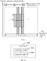
- the NR-PSS is mapped to 12 NR-PRBs, and the specific mapping mode is shown in FIG. 2 .
- the NR-SSS is mapped to the same subcarriers on a corresponding OFDM symbol as the NR-PSS.
- an SS block includes specific time information of a current transmission, which includes: a system frame number (hereinafter referred to as SFN), and an indication co for indicating whether the SS block is in the first 5ms or in the last 5ms of a system frame where the SS block is located, and a time index of the SS block.
- SFN system frame number
- an SS block time index of an NR-PBCH that is currently transmitted by a terminal needs to be indicated in the NR-PBCH, the SS block time index at most has 64 possibilities, and information having a maximum of 6 bits needs to be transmitted.
- the SS block time index is transmitted in two parts, where 2 bits or 3 bits are indicated through a demodulation reference signal (hereinafter referred to as DMRS) sequence of the NR-PBCH, and the remaining bits are transmitted through a payload of the NR-PBCH.
- DMRS demodulation reference signal
- a terminal can obtain part of the SS block time index without NR-PBCH detection and NR-PBCH decoding when performing a neighboring cell measurement, by carrying 2 bits or 3 bits of the SS block time index through the DMRS of the NR-PBCH.
- the 2 bits or 3 bits still can not indicate whether a currently transmitted SS block is in the first 5ms or in the last 5ms of a system frame, resulting in that the terminal can not determine a position relation between the SS block and the system frame.
- Document D1 VIVO: "Discussion on SS block time index indication", 3GPP DRAFT; R1-1710373, 3RD GENERATION PARTNERSHIP PROJECT (3GPP), MOBILE COMPETENCE CENTRAL; 650, ROUTE DES LUCIOLES; F-06921 SOPHIA-ANTIPOLIS CEDEX; FRANCE ) discusses and evaluates NR-PBCH DMRS phase rotation mechanism to indicate SS block time index. Proposal 1 is arrived: NR-PBCH DMRS phase rotation should be adopted as one of techniques in NR to carry implicit information.
- Document D2 NTT DECOMO ET AL: "Discussion sequence design of DMRS for NR-PBCH", 3GPP DRAFT; R1-1711062, 3RD GENERATION PARTNERSHIP PROJECT (3GPP), MOBILE COMPETENCE CENTRAL; 650, ROUTE DES LUCIOLES; F-06921 SOPHIA-ANTIPOLIS CEDEX; FRANCE ) discloses: forPBCH DMRS sequence pattern/mapping, some dependency with time index information such as SS block index should be considered with taking UE blind detection effort into account.
- NR-PBCH coded bits are mapped across REs in N PBCH symbols within the bandwidth of PSS/SSS, and the NR-PBCH band within the bandwidth of PSS/SSS is copied to other NR-PBCH band in a NR-SS block.
- a method for transmitting a DMRS of a physical broadcast channel is provided according to an embodiment of the present disclosure, which is applied to a network device side. As shown in FIG. 4 , the method specifically includes the following steps 41 and 42.
- Step 41 configuring a DMRS sequence of an NR-PBCH.
- An SS block includes specific time information of a current transmission, including: SFN, indication c 0 for indicating whether the SS block is in the first 5ms or in the last 5ms of a system frame where the SS block is located, and a time index of the SS block (SS Block time index).
- the DMRS sequence is used to indicate a position relation between an SS block to which the NR-PBCH belongs and a system frame where the SS block is located.
- the position relation between the SS block to which the NR-PBCH belongs and the system frame where the SS block is located includes: the SS block being located in the first 5ms of the system frame where the SS block is located; or the SS block being located in the last 5ms of the system frame where the SS block is located. That is, the DMRS sequence implicitly carries the indication co. Further, the NR-PBCH occupies two OFDM symbols, and DMRS sequences transmitted on the two OFDM symbols may be two sequences that are independent and different, or two sequences that are identical, or may form one complete sequence.
- Step 42 transmitting the DMRS sequence of the NR-PBCH to a terminal.
- the terminal receives the DMRS sequence of the NR-PBCH that is configured and transmitted by a network device, and the DMRS sequence implicitly indicates the position relation between the SS block and the system frame where the SS block is located.
- the terminal can obtain the position relation between the SS block and the system frame where the SS block is located, so as to solve a problem that a position relation between a currently transmitted SS block and a system frame can not be indicated in an NR system. Therefore, an SS block can be accurately detected in transmission resources of a system frame.
- a terminal can obtain the position relation between the SS block and the system frame based on the DMRS sequence, thereby improving utilization efficiency of the DMRS sequence.
- step 41 may be implemented with reference to the following manners.
- a first manner includes: configuring phase rotation information of the DMRS sequence of the NR-PBCH.
- the phase rotation information of the DMRS sequence is used to indicate the position relation between the SS block to which the NR-PBCH belongs and the system frame where the SS block is located, which includes: the SS block being located in the first 5ms of the system frame where the SS block is located; or the SS block being located in the last 5ms of the system frame where the SS block is located.
- the phase rotation information includes information about a phase difference of a phase of a DMRS sequence transmitted on a second time-domain symbol in transmission resources of the NR-PBCH relative to a phase of a DMRS sequence transmitted on a first time-domain symbol in the transmission resources of the NR-PBCH.
- 1-bit information is indicated by using a phase rotation between DMRS sequences on OFDM symbols where two NR-PBCHs are located, that is, the above indication co that the SS block is located in the first 5ms or in the last 5ms of the system frame where the SS block is located.
- the 1-bit information is transmitted through different phase rotations between the DMRS sequences on the OFDM symbols where the two NR-PBCHs is located. For example, phase rotations of ⁇ 0, ⁇ are introduced to the second OFDM symbol, as shown in FIG. 5 .
- the DMRS sequence on the first OFDM symbol is shown in FIG. 5 .
- this case indicates that the SS block where the NR-PBCH is located is in the first 5ms of the system frame; and in a case that a phase of the DMRS sequence on the second OFDM symbol rotates by ⁇ (the phase rotation is ⁇ ) relative to a phase of the DMRS sequence on the first OFDM symbol, this case indicates that the SS block where the NR-PBCH is located is in the last 5ms of the system frame.
- a second manner includes: configuring a mapping mode of the DMRS sequence of the NR-PBCH.
- the mapping mode of the DMRS sequence is used to indicate the position relation between the SS block to which the NR-PBCH belongs and the system frame where the SS block is located, that is, whether the SS block is located in the first 5ms or in the last 5ms of a system frame where the SS block is located.
- the mapping mode of the DMRS sequence includes at least one selected from the group of: a mapping mode based on different orders, a mapping mode based on a time-domain symbol, and a mapping mode based on a frequency band.
- the second manner is to indicate 1-bit information through different mapping modes of the DMRS sequence, that is, the above-mentioned indication co that the SS block is located in the first 5ms or in the last 5ms of the system frame where the SS block is located.
- a mapping mode based on different orders includes: a mapping mode first in a frequency-domain direction and then in a time-domain direction; a mapping mode first in a time-domain direction and then in a frequency-domain direction; a mapping mode in a direction from a low frequency to a high frequency; or a mapping mode in a direction from a high frequency to a low frequency.
- the case implicitly indicates a current SS block is located in the first 5ms of the system frame.
- a mapping mode in an opposite direction from a high frequency to a low frequency
- a DMRS sequence are grouped into different packets on time-frequency resources, and c 0 is indicated by different DMRS sub-sequences mapped to different packets.
- the grouping includes time-domain grouping and frequency-domain grouping.
- a mapping mode based on time-domain symbols includes: the first half of the DMRS sequence corresponding to the first time-domain symbol in transmission resources of the NR-PBCH, and the second half of the DMRS sequence corresponding to the second time-domain symbol in the transmission resources of the NR-PBCH; or the first half of the DMRS sequence corresponding to the second time-domain symbol in transmission resources of the NR-PBCH, and the second half of the DMRS sequence corresponding to the first time-domain symbol in transmission resources of the NR-PBCH.
- a DMRS sequence on the first time-domain symbol of the NR-PBCH is the first half of the DMRS sequence
- a DMRS sequence on the second time-domain symbol of the NR-PBCH is the second half of the DMRS sequence
- it implicitly indicates that a current SS block is in the first 5ms of the system frame
- a DMRS sequence on the first time-domain symbol of the NR-PBCH is the second half of the DMRS sequence
- a DMRS sequence on the second time-domain symbol of the NR-PBCH is the first half of the DMRS sequence
- a mapping mode based on frequency bands includes: the first half of the DMRS sequence corresponding to a first predetermined frequency band in transmission resources of the NR-PBCH, and the second half of the DMRS sequence corresponding to a second predetermined frequency band in transmission resources of the NR-PBCH; or the first half of the DMRS sequence corresponding to a second predetermined frequency band in transmission resources of the NR-PBCH, and the second half of the DMRS sequence corresponding a first predetermined frequency band in transmission resources of the NR-PBCH.
- one DMRS sequence is segmented into two parts according to a frequency band; in a case that the first half of the DMRS sequence is transmitted on a frequency band A, and the second half of the DMRS sequence is transmitted on a frequency band B, the case implicitly indicates that the current SS block is in the first 5ms of the system frame; and in a case that the first half of the DMRS sequence is transmitted on a frequency band B, and the second half of the DMRS sequence is transmitted on a frequency band A, the case implicitly indicates that the current SS block is in the last 5ms of the system frame.
- a third manner includes: configuring a shift used by the DMRS sequence of the NR-PBCH.
- the shift used by the DMRS sequence is used to indicate the position relation between the SS block to which the NR-PBCH belongs and the system frame where the SS block is located, that is, the SS block being located in the first 5ms of the system frame where the SS block is located; or the SS block being located in the last 5ms of the system frame where the SS block is located.
- the third manner is to indicate 1-bit information by using different shifts in the DMRS sequence, that is, the above indication co that the SS block is located in the first 5ms or in the last 5ms of the system frame where the SS block is located.
- the 1-bit information is represented by different shifts of all or part of the DMRS sequences on two OFDM symbols where the NR-PBCHs are located.
- a shift vo is used in the DMRS sequence, as shown in FIG. 8
- transmission bit 1 which implicitly indicates that the current SS block is in the first 5ms of the system frame
- a shift vi is used in the DMRS sequence, as shown in FIG. 9
- transmission bit 1 which implicitly indicates that the current SS block is in the last 5ms of the system frame.
- a fourth manner includes: configuring the DMRS sequence of the NR-PBCH as a gold sequence.
- the gold sequence is used to indicate the position relation between the SS block to which the NR-PBCH belongs and the system frame where the SS block is located, that is, whether the SS block is located in the first 5ms or in the last 5ms of a system frame where the SS block is located.
- 1-bit information is indicated by using different gold sequences of the DMRS sequence, that is, the above-mentioned indication co that the SS block is located in the first 5ms or in the last 5ms of the system frame where the SS block is located.
- Step 41 may be implemented specifically with reference to the following manners.
- a fifth manner includes: configuring a predetermined parameter of the DMRS sequence of the NR-PBCH.
- the predetermined parameter is used to indicate M bits in an SS block time index, and M is an integer greater than 0. Specifically, M may be 2 or 3.
- the predetermined parameter includes at least one of the following parameters: a gold sequence used by the DMRS sequence, a mapping mode of the gold sequence, an initialization mode of the gold sequence, or a shift of the gold sequence.
- 2 bits or 3 bits in the SS block time index are indicated through the DMRS sequence.
- the 2 bits or 3 bits may be high-order bits, low-order bits, or any of the bits in the SS block time index.
- the 2 bits or 3 bits in the SS block time index may be indicated by different gold sequences, different initialization modes, different mapping modes, and/or different shifts used by the DMRS sequence.
- the indicating manner based on different gold sequences may specifically include: indicating 2 bits in the SS block time index through 4 different gold sequences (a length of a sequence shift register or a generator polynomial), or indicating 3 bits in the SS block time index through 8 different gold sequences. Additionally, 2 bits or 3 bits in the SS block time index, and c 0 may be indicated by different gold sequences, that is, indicating co and 2 bits or 3 bits in the SS block time index by 8 or 16 gold sequences (a length of a sequence shift register or a generator polynomial).
- Different initialization modes of a gold sequence are related to a cell ID, and may also be related to the SS block time index, and 2 bits or 3 bits of the SS block time index are indicated through different initializations.
- different DMRS sequences are generated based on different sequence initializations S ID , different shift values, or different generator polynomials, and different information is indicated by different DMRS sequences. For example, when 1-bit information is required to be indicated through two DMRS sequences, sequences with two different initializations S ID , or two differently shifted sequences, or gold sequences with two different generator polynomials are used for indication.
- different DMRS sequences may be generated based on a combination of two manners of using different sequence initializations S ID and using different shift values, and different information is indicated by different DMRS sequences.
- S ID ⁇ 0,1 ⁇
- S ID ⁇ 0,1 ⁇
- different information may be indicated through different sequence initializations S ID .
- S ID ⁇ 0,1, ...,7 ⁇
- S ID ⁇ 0,1, ...,7 ⁇
- 1-bit information may further be indicated through different mapping modes.
- 2-bit information needs to be transmitted on a part of DMRS resources, which may be indicated as follows: two sequences using two different initializations S ID or using two different shifts may be defined to indicate 1-bit information, and the other 1-bit information is indicated by a forward mapping or a reverse mapping on DMRS resources.
- 2 bits or 3 bits of the SS block time index may be indicated by different mapping modes, or different shifts of a gold sequence, or different mapping orders.
- a method of indicating the SS block time index in different mapping modes is similar to the method of indicating the position relation between the SS block and the system frame in which the SS block is located in the second manner, which is not repeated herein.
- a network device configures a DMRS sequence of an NR-PBCH for a terminal, where the DMRS sequence implicitly indicates a position relation between an SS block and a system frame where the SS block is located, and the network device transmits the configured DMRS sequence to a terminal, so that the terminal obtains the position relation between the SS block and the system frame where the SS block is located, so as to solve a problem that whether a currently transmitted SS block and a system frame is in the first 5ms or in the last 5ms of the system frame can not be indicated in an NR system. Therefore, a position of a current SS block in a system frame can be more accurately indicated.
- a network device 1000 is provided according to an embodiment of the present disclosure, which can implement the method details of configuring a demodulation reference signal DMRS sequence of a new radio physical broadcast channel NR-PBCH and transmitting the DMRS sequence of the NR-PBCH to a terminal, and achieves the same effects, where the DMRS sequence is configured to indicate a position relation between an SS block to which the NR-PBCH belongs and a system frame where the SS block is located.
- the network device 1000 specifically includes the following functional modules:
- the configuration module 1010 includes: a first configuration unit, configured to configure phase rotation information of the DMRS sequence of the NR-PBCH, where the phase rotation information of the DMRS sequence is configured to indicate the position relation between the SS block to which the NR-PBCH belongs and the system frame where the SS block is located, and the phase rotation information includes information of a phase difference between a phase of a DMRS sequence transmitted on a second time-domain symbol in transmission resources of the NR-PBCH and a phase of a DMRS sequence transmitted on a first time-domain symbol in the transmission resources of the NR-PBCH.
- the configuration module 1010 further includes: a second configuration unit, configured to configure a mapping mode of the DMRS sequence of the NR-PBCH, where the mapping mode of the DMRS sequence is configured to indicate the position relation between the SS block to which the NR-PBCH belongs and the system frame where the SS block is located.
- a second configuration unit configured to configure a mapping mode of the DMRS sequence of the NR-PBCH, where the mapping mode of the DMRS sequence is configured to indicate the position relation between the SS block to which the NR-PBCH belongs and the system frame where the SS block is located.
- the mapping mode of the DMRS sequence includes at least one selected from the group of: a mapping mode based on different orders, a mapping mode based on a time-domain symbol, and a mapping mode based on a frequency band.
- the configuration module 1010 further includes: a third configuration unit, configured to configure a shift used by the DMRS sequence of the NR-PBCH; where the shift used in the DMRS sequence of the NR-PBCH is configured to indicate the position relation between the SS block to which the NR-PBCH belongs and the system frame where the SS block is located.
- a third configuration unit configured to configure a shift used by the DMRS sequence of the NR-PBCH; where the shift used in the DMRS sequence of the NR-PBCH is configured to indicate the position relation between the SS block to which the NR-PBCH belongs and the system frame where the SS block is located.
- the configuration module 1010 includes: a fourth configuration unit, configured to configure the DMRS sequence of the NR-PBCH as a gold sequence, where the gold sequence is configured to indicate the position relation between the SS block to which the NR-PBCH belongs and the system frame where the SS block is located.
- the configuration module 1010 further includes: a fifth configuration unit, configured to configure a predetermined parameter of the DMRS sequence of the NR-PBCH, where the predetermined parameter is configured to indicate M bits in an SS block time index, and M is an integer greater than 0.
- the predetermined parameter includes at least one selected from the following parameters: a gold sequence used by the DMRS sequence, a mapping mode of the gold sequence, an initialization mode of the gold sequence, and a shift of the gold sequence.
- the position relation between the SS block to which the NR-PBCH belongs and the system frame where the SS block is located includes: the SS block being located in a first 5ms or in a last 5ms of the system frame where the SS block is located.
- the network device configures a DMRS sequence of an NR-PBCH for a terminal, where the DMRS sequence implicitly indicates a position relation between an SS block and a system frame where the SS block is located, and the network device transmits the configured DMRS sequence to a terminal, so that the terminal obtains the position relation between the SS block and the system frame where the SS block is located, so as to solve a problem that whether a currently transmitted SS block is in the first 5ms or in the last 5ms of the system frame can not be indicated in an NR system. Therefore, a position of a current SS block in a system frame can be more accurately indicated.
- an embodiment of the present disclosure further provides a network device.
- the network device includes a processor, a memory, and a computer program stored on the memory and executable on the processor.
- the processor When executing the computer program, the processor is configured to implement steps in the method for transmitting a DMRS of a physical broadcast channel as described above.
- An embodiment of the present disclosure further provides a computer-readable storage medium.
- the computer-readable storage medium stores a computer program, and the computer program is executed by a processor to implement steps in the method for transmitting a DMRS of a physical broadcast channel as described above.
- the network device 1100 includes: an antenna 111, a radio frequency (RF) device 112 and a baseband device 113.
- the antenna 111 is connected to the RF device 112.
- the RF device 112 receives information through the antenna 111 and transmits the received information to the baseband device 113 for processing.
- the baseband device 113 processes information to be transmitted and transmits the information to the RF device 112, and the RF device 112 processes the received information and transmits the processed information out via the antenna 111.
- the above-mentioned frequency band processing device may be located in the baseband device 113.
- the method performed by the network device in the above embodiments may be implemented in the baseband device 113.
- the baseband device 113 includes a processor 114 and a memory 115.
- the baseband device 113 may include, for example, at least one baseband board.
- a plurality of chips is provided on the baseband board, as shown in FIG. 11 .
- One of the chips is, for example, the processor 114 and is connected to the memory 115 to invoke a program in the memory 115 to perform operations of the network device in the above method embodiments.
- the baseband device 113 may further include a network interface 116 for exchanging information with the RF device 112.
- the interface is, for example, a common public radio interface (CPRI).
- CPRI common public radio interface
- the processor herein may be a processor or a collective name for multiple processing elements.
- the processor may be a CPU, an ASIC, or one or more integrated circuits configured to implement the methods performed by the above network device, such as: one or more micro-processors DSPs, or one or more field programmable gate array FPGAs.
- a storage element may be a single memory or a collective term for multiple storage elements.
- the memory 115 may be a volatile memory or a non-volatile memory, or may include both of the volatile memory and the non-volatile memory.
- the non-volatile memory may be a read-only memory (ROM), a programmable ROM (PROM), an erasable PROM (EPROM), an electrically EPROM (EEPROM) or a flash memory.
- the volatile memory may be a random access memory (RAM), which is used as an external cache.
- RAM random access memory
- many forms of RAMs may be used, such as static RAM (SRAM), dynamic RAM (DRAM), synchronous DRAM (SDRAM), double data rate SDRAM (DDRSDRAM), enhanced SDRAM (ESDRAM), Synchlink DRAM (SLDRAM) and direct Rambus RAM (DRRAM).
- SRAM static RAM
- DRAM dynamic RAM
- SDRAM synchronous DRAM
- DDRSDRAM double data rate SDRAM
- ESDRAM enhanced SDRAM
- SLDRAM Synchlink DRAM
- DRRAM direct Rambus RAM
- the network device further includes: a computer program stored in the memory 115 and executable on the processor 114, and the processor 114 is configured to call the computer program in the memory 115 to perform the method executed by each module shown in FIG. 10 .
- the processor 114 may be configured to: configure a demodulation reference signal DMRS sequence of a new radio physical broadcast channel NR-PBCH, where the DMRS sequence is configured to indicate a position relation between a synchronization signal block (SS block) to which the NR-PBCH belongs and a system frame where the SS block is located; and transmit the DMRS sequence of the NR-PBCH to a terminal.
- a demodulation reference signal DMRS sequence of a new radio physical broadcast channel NR-PBCH where the DMRS sequence is configured to indicate a position relation between a synchronization signal block (SS block) to which the NR-PBCH belongs and a system frame where the SS block is located
- the processor 114 may be configured to: configure phase rotation information of the DMRS sequence of the NR-PBCH, where the phase rotation information of the DMRS sequence is configured to indicate the position relation between the SS block to which the NR-PBCH belongs and the system frame where the SS block is located.
- the processor 114 may be configured to: configure a mapping mode of the DMRS sequence of the NR-PBCH, where the mapping mode of the DMRS sequence is configured to indicate the position relation between the SS block to which the NR-PBCH belongs and the system frame where the SS block is located.
- the phase rotation information includes information of a phase difference between a phase of a DMRS sequence transmitted on a second time-domain symbol in transmission resources of the NR-PBCH and a phase of a DMRS sequence transmitted on a first time-domain symbol in the transmission resources of the NR-PBCH.
- the mapping mode of the DMRS sequence includes at least one of: a mapping mode based on different orders, a mapping mode based on a time-domain symbol, or a mapping mode based on a frequency band.
- the processor 114 may be configured to: configure a shift used by the DMRS sequence of the NR-PBCH; where the shift used by the DMRS sequence of the NR-PBCH is configured to indicate the position relation between the SS block to which the NR-PBCH belongs and the system frame where the SS block is located.
- the processor 114 may be configured to: configure the DMRS sequence of the NR-PBCH as a gold sequence, where the gold sequence is configured to indicate the position relation between the SS block to which the NR-PBCH belongs and the system frame where the SS block is located.
- the processor 114 may be configured to: configure a predetermined parameter of the DMRS sequence of the NR-PBCH, where the predetermined parameter is configured to indicate M bits in an SS block time index, and M is an integer greater than 0.
- the predetermined parameter includes at least one of the following parameters: a gold sequence used by the DMRS sequence, a mapping mode of the gold sequence, an initialization mode of the gold sequence, or a shift of the gold sequence.
- the position relation between the SS block to which the NR-PBCH belongs and the system frame where the SS block is located includes: the SS block being located in a first 5ms or in a last 5ms of the system frame where the SS block is located.
- a network device may be a global system of mobile communication (GSM) or a code division multiple access (CDMA) base transceiver station (BTS), or a wideband code division multiple access (WCDMA) NodeB (NB), or a LTE evolutional Node B (eNB or eNodeB), or a new radio access technical (New RAT or NR) base station, or a relay station or access point, or a future 5G network base station, etc., which is not limited herein.
- GSM global system of mobile communication
- CDMA code division multiple access
- BTS wideband code division multiple access
- NB wideband code division multiple access
- eNB or eNodeB LTE evolutional Node B
- New RAT or NR new radio access technical
- a position relation between an SS block and a system frame is indicated through a DMRS sequence, so that a terminal can obtain the position relation between the SS block and the system frame according to the DMRS sequence, thereby improving utilization efficiency of the DMRS sequence.
- the method for transmitting a DMRS of a physical broadcast channel applied in the network device side is described in above embodiments of the present disclosure.
- a method for transmitting a DMRS of a physical broadcast channel applied in a terminal side will be further described in conjunction with the accompanying drawings in the following embodiments.
- a method for transmitting a DMRS of a physical broadcast channel is provided according to an embodiment of the present disclosure, which is applied to a terminal side, and specifically includes the following steps 121 and 122.
- Step 121 receiving a demodulation reference signal DMRS sequence of a new radio physical broadcast channel NR-PBCH transmitted by a network device.
- a position relation between a synchronization signal block (SS block) to which the NR-PBCH belongs and a system frame is different for different DMRS sequences.
- An SS block includes specific time information of a current transmission, including: SFN, indication co for indicating whether the SS block is in the first 5ms or in the last 5ms of a system frame where the SS block is located, and a time index of the SS block (SS Block time index).
- the DMRS sequence is configured to indicate a position relation between an SS block to which the NR-PBCH belongs and a system frame where the SS block is located.
- the position relation between the SS block to which the NR-PBCH belongs and the system frame where the SS block is located includes: the SS block being located in the first 5ms of the system frame where the SS block is located; or the SS block being located in the last 5ms of the system frame where the SS block is located. That is, the DMRS sequence implicitly carries the indication co.
- Step 122 determining, according to the DMRS sequence, a position relation between a synchronization signal block (SS block) to which the NR-PBCH belongs and a system frame where the SS block is located.
- SS block synchronization signal block
- the terminal receives the DMRS sequence of the NR-PBCH that is configured and transmitted by a network device, and obtains the position relation between the SS block and the system frame where the SS block is located, so as to solve a problem that whether a currently transmitted SS block is in the first 5ms or in the last 5ms of the system frame can not be indicated in an NR system. Therefore, a current SS block can be accurately detected in transmission resources of a system frame.
- a position relation between an SS block and a system frame is indicated through a DMRS sequence, so that a terminal can obtain the position relation between the SS block and the system frame according to the DMRS sequence, thereby improving utilization efficiency of the DMRS sequence.
- step 122 may be implemented with reference to the following manners.
- a manner includes: detecting the DMRS sequence to determine phase rotation information of the DMRS sequence of the NR-PBCH; and determining, according to the phase rotation information, the position relation between the SS block to which the NR-PBCH belongs and the system frame where the SS block is located.
- the phase rotation information includes information of a phase difference between a phase of a DMRS sequence transmitted on a second time-domain symbol in transmission resources of the NR-PBCH and a phase of a DMRS sequence transmitted on a first time-domain symbol in the transmission resources of the NR-PBCH.
- the phase rotation information is used to implicitly indicate that the SS block is located in the first 5ms of the system frame where the SS block is located; or the SS block is located in the last 5ms of the system frame where the SS block is located.
- This manner corresponds to the first manner, and specific implementations of this manner can refer to the implementations of the above first manner, which will not be repeated herein.
- a manner includes: detecting the DMRS sequence to determine a mapping mode of the DMRS sequence of the NR-PBCH; and determining, according to the mapping mode of the DMRS sequence, the position relation between the SS block to which the NR-PBCH belongs and the system frame where the SS block is located.
- the mapping mode of the DMRS sequence is used to implicitly indicate that the SS block is located in the first 5ms of the system frame where the SS block is located; or the SS block is located in the last 5ms of the system frame where the SS block is located.
- This manner corresponds to the second manner, and specific implementations of this manner can refer to the implementations of the above second manner, which will not be repeated herein.
- the mapping mode of the DMRS sequence includes at least one of: a mapping mode based on different orders, a mapping mode based on a time-domain symbol, or a mapping mode based on a frequency band.
- a manner includes: detecting the DMRS sequence to determine a shift used by the DMRS sequence of the NR-PBCH; and determining, according to the shift used by the DMRS sequence, the position relation between the SS block to which the NR-PBCH belongs and the system frame where the SS block is located.
- the shift used by the DMRS sequence is used to implicitly indicate that the SS block is located in the first 5ms of the system frame where the SS block is located; or the SS block is located in the last 5ms of the system frame where the SS block is located.
- This manner corresponds to the third manner, and specific implementations of this manner can refer to the implementations of the above third manner, which will not be repeated herein.
- a manner includes: detecting the DMRS sequence to determine that the DMRS sequence of the NR-PBCH is a gold sequence; and determining, according to the gold sequence, the position relation between the SS block to which the NR-PBCH belongs and the system frame where the SS block is located.
- the gold sequence is used to implicitly indicate that the SS block is located in the first 5ms of the system frame where the SS block is located; or the SS block is located in the last 5ms of the system frame where the SS block is located.
- the forgoing embodiments describe a terminal obtaining the position relation between the SS block and the system frame where the SS block is located based on the DMRS sequence.
- the terminal according to an embodiment can further obtain an SS block time index through a DMRS sequence.
- the method further includes: determining an SS block time index of the SS block to which the NR-PBCH belongs according to the DMRS sequence.
- the determining the SS block time index of the SS block to which the NR-PBCH belongs according to the DMRS sequence includes: detecting the DMRS sequence to determine a predetermined parameter of the DMRS sequence; and determining the SS block time index of the SS block to which the NR-PBCH belongs according to the predetermined parameter, where the predetermined parameter is configured to indicate M bits in the SS block time index, M being an integer greater than 0, and M may be 2 or 3.
- M being an integer greater than 0, and M may be 2 or 3.
- the predetermined parameter includes at least one of the following parameters: a gold sequence used by the DMRS sequence, a mapping mode of the gold sequence, an initialization mode of the gold sequence, or a shift of the gold sequence.
- a terminal receives the DMRS sequence of the NR-PBCH that is configured and transmitted by a network device, and obtains the position relation between the SS block and the system frame where the SS block is located, so as to solve a problem that whether a currently transmitted SS block is in the first 5ms or in the last 5ms of the system frame can not be indicated in an NR system. Therefore, a position of a current SS block in a system frame can be more accurately detected.
- a terminal 1300 is provided according to an embodiment of the present disclosure, which can implement the method details of receiving a demodulation reference signal DMRS sequence of a new radio physical broadcast channel NR-PBCH transmitted by a network device; and determining, according to the DMRS sequence, a position relation between an SS block to which the NR-PBCH belongs and a system frame where the SS block is located, and achieves the same effects.
- the terminal 1300 specifically includes the following functional modules:
- the first processing module 1320 includes:
- the first processing module 1320 includes:
- the mapping mode of the DMRS sequence includes at least one of: a mapping mode based on different orders, a mapping mode based on a time-domain symbol, or a mapping mode based on a frequency band.
- the first processing module 1320 includes:
- the first processing module 1320 includes:
- the terminal 1300 further includes: a second processing module, configured to determine an SS block time index of the SS block to which the NR-PBCH belongs according to the DMRS sequence.
- the second processing module includes:
- the predetermined parameter includes at least one of the following parameters: a gold sequence used by the DMRS sequence, a mapping mode of the gold sequence, an initialization mode of the gold sequence, or a shift of the gold sequence.
- the position relation between the SS block to which the NR-PBCH belongs and the system frame where the SS block is located includes: the SS block being located in a first 5ms or in a last 5ms of the system frame where the SS block is located.
- a position relation between an SS block and a system frame is indicated through a DMRS sequence, so that the terminal can obtain the position relation between the SS block and the system frame according to the DMRS sequence, thereby improving utilization efficiency of the DMRS sequence.
- modules may be integrated entirely or partly to one physical entity or physically separated.
- These modules may be entirely implemented in form of software that may be called and executed by a processing element, or entirely implemented in form of hardware, or partly implemented in form of software that may be called and executed by a processing element and partly implemented in form of hardware.
- a determination module may be a standalone processing element, or integrated in a chip of the device, or may be stored in a storage of the device in form of program code which is configured to be called by a processing element of the device to implement the function of the determination module.
- Other modules may be implemented in a similar way.
- modules may be entirely or partly integrated together, or implemented separately.
- the described processing element may be an integrated circuit with signal processing capability.
- steps of the methods or the modules may be realized in form of hardware by integrated logical circuits in the processing element, or in form of software by instructions.
- these modules may be one or more integrated circuits (IC) configured to implement the foregoing methods, e.g., one or more Application Specific Integrated Circuits (ASIC), one or more Digital Signal Processors (DSP), or one or more Field-Programmable Gate Arrays (FPGA), etc.
- ASIC Application Specific Integrated Circuit
- DSP Digital Signal Processor
- FPGA Field-Programmable Gate Arrays
- the processing element may be a general purpose processor, e.g., a central processing unit (CPU) or other processor configured to call program code.
- these modules may be integrated together in form of a system-on-a-chip (SOC).
- SOC system-on-a-chip
- an embodiment of the present disclosure further provide a terminal.
- the terminal includes a processor, a memory and a computer program stored in the memory and executable by the processor.
- the processor When executing the computer program, the processor is configured to implement steps of the method for transmitting a DMRS of a physical broadcast channel as described above.
- An embodiment of the present disclosure further provides a computer-readable storage medium.
- the computer-readable storage medium stores a computer program, and the computer program is executed by a processor to implement steps of the method for transmitting a DMRS of a physical broadcast channel as described above.
- FIG. 14 is a block diagram of a terminal 1400 provided by another embodiment of the present disclosure.
- the terminal includes: at least one processor 1401, a memory 1402, a user interface 1403, and a network interface 1404.
- Various components in the terminal 1400 are coupled together through a bus system 1405.
- the bus system 1405 is configured to implement connections and communications between these components.
- the bus system 1405 includes a power bus, a control bus, and a status signal bus, in addition to a data bus.
- various buses are all labeled as the bus system 1405 in FIG. 14 .
- the user interface 1403 may include a display, or a click device (e.g., a touchpad), or a touch screen, etc.
- the memory 1402 in embodiments of the present disclosure may be a volatile memory or a non-volatile memory, or may include both of the volatile memory and the non-volatile memory.
- the non-volatile memory may be a read-only memory (ROM), a programmable ROM (PROM), an erasable PROM (EPROM), an electrically EPROM (EEPROM) or a flash memory.
- the volatile memory may be a random access memory (RAM), which is used as an external cache.
- RAMs such as static RAM (SRAM), dynamic RAM (DRAM), synchronous DRAM (SDRAM), double data rate SDRAM (DDRSDRAM), enhanced SDRAM (ESDRAM), Synchlink DRAM (SLDRAM) and direct Rambus RAM (DRRAM).
- SRAM static RAM
- DRAM dynamic RAM
- SDRAM synchronous DRAM
- DDRSDRAM double data rate SDRAM
- ESDRAM enhanced SDRAM
- SLDRAM Synchlink DRAM
- DRRAM direct Rambus RAM
- the memory 1402 stores the following elements: executable module or data structure, or a subset or extension set thereof, such as an operating system 14021 and an application 14022.
- the operating system 14021 includes various system programs, such as framework layer programs, core library layer programs and driver layer programs, to implement various fundamental services and process hardware-based tasks.
- the application 14022 includes various applications, such as media player and browser, to implement a variety of application services.
- the program implementing the method according to embodiments of the present disclosure may be included in the application 14022.
- the terminal 1400 further includes: a computer program stored in the memory 1402 and executable by the processor 1401, specifically, a computer program in the application 14022, and the computer program is executed by the processor 1401 to achieve the following steps: receiving a demodulation reference signal DMRS sequence of a new radio physical broadcast channel NR-PBCH transmitted by a network device; and determining, according to the DMRS sequence, a position relation between a synchronization signal block (SS block) to which the NR-PBCH belongs and a system frame where the SS block is located.
- the method disclosed in the foregoing embodiments of the present disclosure may be applied to the processor 1401 or implemented by the processor 1401.
- the processor 1401 may be an integrated circuit with signal processing capability. During an implementation process, steps of the methods may be realized in form of hardware by integrated logical circuits in the processor 1401, or in form of software by instructions.
- the processor 1401 may be a general purpose processor, digital signal processor (DSP), application specific integrated circuit (ASIC), field programmable gate array (FPGA) or other programmable logic device, discrete gate or transistor logic device, discrete hardware transistor logic device, discrete hardware component, that is capable of implementing or executing the various methods, steps and logic block diagrams disclosed in the embodiments of the present disclosure.
- the general purpose processor may be a microprocessor, or any conventional processor, etc.
- the steps of the methods disclosed with reference to the embodiments of the present disclosure may be embodied in hardware in the form of a coding processor, or performed by the hardware in the coding processor and the software modules in combination.
- the software modules may reside in well-established storage medium in the art, such as a RAM, flash memory, ROM, PROM or EEPROM, register, etc.
- the storage medium resides in the memory 1402.
- the processor 1401 reads information from the memory 1402 and performs the steps of the methods with its hardware.
- processing units may be implemented in one or more application specific integrated circuits (ASIC), digital signal processor (DSP), DSP device (DSPD), programmable logic device (PLD), field-programmable gate array (FPGA), general purpose processor, controller, microcontroller, microprocessor, other electronic unit configured to perform the function described in this application or a combination thereof.
- ASIC application specific integrated circuits
- DSP digital signal processor
- DSPD DSP device
- PLD programmable logic device
- FPGA field-programmable gate array
- controller microcontroller
- microprocessor other electronic unit configured to perform the function described in this application or a combination thereof.
- the technical solutions described in the embodiments of the present disclosure may be implemented by a module (e.g., process, function, etc.) configured to perform the function described in the embodiments of the present disclosure.
- Software code may be stored in a storage and executed by the processor.
- the storage may be implemented internal or external to the processor.
- the computer program is configured to be executed by the processor 1401 to implement following steps:
- the computer program is configured to be executed by the processor 1401 to implement following steps:
- the mapping mode of the DMRS sequence includes at least one of: a mapping mode based on different orders, a mapping mode based on a time-domain symbol, or a mapping mode based on a frequency band.
- the computer program is configured to be executed by the processor 1401 to implement following steps: detecting the DMRS sequence to determine a shift used by the DMRS sequence of the NR-PBCH; and determining, according to the shift used by the DMRS sequence, the position relation between the SS block to which the NR-PBCH belongs and the system frame where the SS block is located.
- the computer program is configured to be executed by the processor 1401 to implement following steps: detecting the DMRS sequence to determine that the DMRS sequence of the NR-PBCH is a gold sequence; and determining, according to the gold sequence, the position relation between the SS block to which the NR-PBCH belongs and the system frame where the SS block is located.
- the computer program is configured to be executed by the processor 1401 to implement following steps: determining an SS block time index of the SS block to which the NR-PBCH belongs according to the DMRS sequence.
- the computer program is configured to be executed by the processor 1401 to implement following steps: detecting the DMRS sequence to determine a predetermined parameter of the DMRS sequence, where the predetermined parameter is configured to indicate M bits in the SS block time index, M being an integer greater than 0; and determining the SS block time index of the SS block to which the NR-PBCH belongs according to the predetermined parameter.
- the predetermined parameter includes at least one of the following parameters: a gold sequence used by the DMRS sequence, a mapping mode of the gold sequence, an initialization mode of the gold sequence, or a shift of the gold sequence.
- the position relation between the SS block to which the NR-PBCH belongs and the system frame where the SS block is located includes: the SS block being located in a first 5ms or in a last 5ms of the system frame where the SS block is located.
- the terminal may be a wireless terminal or a wired terminal.
- a wireless terminal may refer to a device used to provide voice and/or other service data connectivity to a user, a hand-held device with a wireless connection function, or another processing device connected to a wireless modem.
- a wireless terminal may communicate with one or more core networks via a radio access network (RAN).
- the wireless terminal may be a mobile terminal, such as a mobile phone (also called cellphone) or a computer equipped with a mobile terminal, such as a portable, pocket-sized, hand-held, computer built-in, or vehicle-mounted mobile device, which exchanges voice and/or data with the radio access network.
- a wireless terminal may also be referred to as a system, a subscriber unit, a subscriber station, a mobile station, a mobile, a remote station, a remote terminal, an access terminal, a user terminal, a user agent, or a user device or user equipment, and is not limited herein.
- a position relation between an SS block and a system frame is indicated through a DMRS sequence, so that a terminal can obtain the position relation between the SS block and the system frame based on the DMRS sequence, thereby improving utilization efficiency of the DMRS sequence.
- the disclosed device and method may be implemented in other manners.
- the described device embodiment is merely exemplary.
- the unit division is merely logical function division and may be other division in actual implementation.
- a plurality of units or components may be combined or integrated into another system, or some features may be neglected or not performed.
- the displayed or discussed mutual couplings or direct couplings or communication connections may be implemented through some interfaces.
- the indirect couplings or communication connections between the devices or units may be implemented in electric, mechanical, or other forms.
- the units described as separate parts may or may not be physically separate, and parts displayed as units may or may not be physical units, that is, may be located in one position, or may be distributed on a plurality of network units. A part or all of the units may be selected according to actual needs to achieve the objectives of the solutions of the embodiments.
- the functions may be stored in a computer-readable storage medium.
- the software product is stored in a storage medium, and includes several instructions for instructing a computer device (which may be a personal computer, a server, or a network device) to perform all or a part of the steps of the methods described in the embodiments of the disclosure.
- the foregoing storage medium includes any medium that may store program code, such as a universal serial bus (USB) flash drive, a mobile hard disk, an ROM, an RAM, a magnetic disk, or an optical disc.
- USB universal serial bus
- the objective of the present disclosure may further be achieved by running a program or a group of programs on any computing device.
- the computing device may be a well-known general-purpose device.
- the objective of the present disclosure may further be achieved by providing a program product including program codes configured to implement the method or apparatus.
- a program product constitutes the present disclosure
- a storage medium storing such a program product also constitutes the present disclosure.
- the storage medium may be any well-known storage medium or any storage medium to be developed in the future.
- the components or steps in the apparatus and method of the present disclosure may be subdivided and/or recombined. These subdivisions and/or recombinations should be considered as equivalent solutions to the present disclosure.
- the steps of the foregoing series of process may be performed naturally in a chronological order in which the steps are described, however, the steps are not necessarily performed in the chronological order. Instead, some steps may be performed concurrently or independently of each other.
Landscapes
- Engineering & Computer Science (AREA)
- Signal Processing (AREA)
- Computer Networks & Wireless Communication (AREA)
- Quality & Reliability (AREA)
- Mobile Radio Communication Systems (AREA)
Claims (15)
- Verfahren zum Übertragen eines DMRS eines physikalischen Rundfunkkanals, angewendet auf eine Netzwerkgeräteseite, und Folgendes umfasst:Konfigurieren (41) einer Demodulationsreferenzsignal-DMRS-Sequenz eines neuen physikalischen Rundfunkkanals NR-PBCH, wobei die DMRS-Sequenz konfiguriert ist, um eine Positionsbeziehung zwischen einem Synchronisationssignalblock, SS-Block, zu dem der NR-PBCH gehört, und einem Systemrahmen, in dem sich der SS-Block befindet, anzuzeigen; undÜbertragen (42) der DMRS-Sequenz des NR-PBCH an ein Endgerät,wobei die Positionsbeziehung zwischen dem SS-Block, zu dem der NR-PBCH gehört, und dem Systemrahmen, in dem sich der SS-Block befindet, Folgendes umfasst:der SS-Block befindet sich in den ersten 5 ms oder in den letzten 5 ms des Systemrahmens, in dem sich der SS-Block befindet;
unddas Konfigurieren (41) der DMRS-Sequenz des NR-PBCH umfasst:Konfigurieren eines Abbildungsmodus der DMRS-Sequenz des NR-PBCH, wobei der Abbildungsmodus der DMRS-Sequenz konfiguriert ist, um die Positionsbeziehung zwischen dem SS-Block, zu dem der NR-PBCH gehört, und dem Systemrahmen, in dem sich der SS-Block befindet, anzuzeigen, wobei der Abbildungsmodus der DMRS-Sequenz mindestens einen umfasst von: einem Abbildungsmodus basierend auf unterschiedlichen Ordnungen, einem Abbildungsmodus basierend auf einem Zeitdomänensymbol, oder einem Abbildungsmodus basierend auf einem Frequenzband,wobei der Abbildungsmodus basierend auf unterschiedlichen Ordnungen umfasst: einen Abbildungsmodus zuerst in einer Frequenzdomänenrichtung und dann in einer Zeitdomänenrichtung; einen Abbildungsmodus zuerst in einer Zeitdomänenrichtung und dann in einer Frequenzdomänenrichtung; einen Abbildungsmodus in einer Richtung von einer niedrigen Frequenz zu einer hohen Frequenz; oder einen Abbildungsmodus in einer Richtung von einer hohen Frequenz zu einer niedrigen Frequenz;wobei der Abbildungsmodus basierend auf dem Zeitdomänensymbol umfasst: eine erste Hälfte der DMRS-Sequenz, die einem ersten Zeitdomänensymbol in Übertragungsressourcen des NR-PBCH entspricht, und eine zweite Hälfte der DMRS-Sequenz, die einem zweiten Zeitdomänensymbol in den Übertragungsressourcen des NR-PBCH entspricht; oder die erste Hälfte der DMRS-Sequenz, die dem zweiten Zeitdomänensymbol in den Übertragungsressourcen des NR-PBCH entspricht, und die zweite Hälfte der DMRS-Sequenz, die dem ersten Zeitdomänensymbol in den Übertragungsressourcen des NR-PBCH entspricht;wobei der Abbildungsmodus basierend auf dem Frequenzband umfasst: die erste Hälfte der DMRS-Sequenz, die einem ersten vorbestimmten Frequenzband in den Übertragungsressourcen des NR-PBCH entspricht, und die zweite Hälfte der DMRS-Sequenz, die einem zweiten vorbestimmten Frequenzband in die Übertragungsressourcen des NR-PBCH entspricht; oder die erste Hälfte der DMRS-Sequenz, die dem zweiten vorbestimmten Frequenzband in den Übertragungsressourcen des NR-PBCH entspricht, und die zweite Hälfte der DMRS-Sequenz, die dem ersten vorbestimmten Frequenzband in den Übertragungsressourcen des NR-PBCH entspricht. - Verfahren zum Übertragen eines DMRS eines physikalischen Rundfunkkanals nach Anspruch 1, wobei das Konfigurieren (41) der DMRS-Sequenz des NR-PBCH umfasst:
Konfigurieren von Phasendrehungsinformationen der DMRS-Sequenz des NR-PBCH, wobei die Phasendrehungsinformationen der DMRS-Sequenz konfiguriert sind, um die Positionsbeziehung zwischen dem SS-Block, zu dem der NR-PBCH gehört, und dem Systemrahmen, in dem sich der SS-Block befindet, anzuzeigen und die Phasendrehungsinformationen Informationen über eine Phasendifferenz zwischen einer Phase einer auf einem zweiten Zeitdomänensymbol übertragenen DMRS-Sequenz in Übertragungsressourcen des NR-PBCH und einer Phase einer auf einem ersten Zeitdomänensymbol übertragenen DMRS-Sequenz in den Übertragungsressourcen des NR-PBCH umfassen. - Verfahren zum Übertragen eines DMRS eines physikalischen Rundfunkkanals nach Anspruch 1, wobei das Konfigurieren (41) der DMRS-Sequenz des NR-PBCH umfasst:Konfigurieren einer von der DMRS-Sequenz des NR-PBCH verwendeten Verschiebung; wobei die von der DMRS-Sequenz verwendete Verschiebung so konfiguriert ist, dass sie die Positionsbeziehung zwischen dem SS-Block, zu dem der NR-PBCH gehört, und dem Systemrahmen, in dem sich der SS-Block befindet, anzeigt; oderKonfigurieren der DMRS-Sequenz des NR-PBCH als Goldsequenz, wobei die Goldsequenz konfiguriert ist, um die Positionsbeziehung zwischen dem SS-Block, zu dem der NR-PBCH gehört, und dem Systemrahmen, in dem sich der SS-Block befindet, anzuzeigen.
- Verfahren zum Übertragen eines DMRS eines physikalischen Rundfunkkanals nach Anspruch 1, wobei das Konfigurieren (41) der DMRS-Sequenz des NR-PBCH umfasst:Konfigurieren eines vorbestimmten Parameters der DMRS-Sequenz des NR-PBCH, wobei der vorbestimmte Parameter konfiguriert ist, um M Bits in einem SS-Blockzeitindex anzuzeigen, und M eine ganze Zahl größer als 0 ist; undwobei der vorbestimmte Parameter mindestens einen umfasst, der aus den folgenden Parametern ausgewählt ist:
eine von der DMRS-Sequenz verwendete Goldsequenz, einen Abbildungsmodus der Goldsequenz, einen Initialisierungsmodus der Goldsequenz und eine Verschiebung der Goldsequenz. - Netzwerkgerät, umfassend:ein Konfigurationsmodul (1010), das konfiguriert ist, um eine Demodulationsreferenzsignal-DMRS-Sequenz eines neuen physikalischen Rundfunkkanals NR-PBCH zu konfigurieren, wobei die DMRS-Sequenz konfiguriert ist, um eine Positionsbeziehung zwischen einem Synchronisationssignalblock, SS-Block, zu dem der NR-PBCH gehört, und einem Systemrahmen, in dem sich der SS-Block befindet, anzuzeigen; undein Übertragungsmodul (1020), das konfiguriert ist, um die DMRS-Sequenz des NR-PBCH an ein Endgerät zu übertragen,wobei die Positionsbeziehung zwischen dem SS-Block, zu dem der NR-PBCH gehört, und dem Systemrahmen, in dem sich der SS-Block befindet, Folgendes umfasst:der SS-Block befindet sich in den ersten 5 ms oder in den letzten 5 ms des Systemrahmens, in dem sich der SS-Block befindet;
unddas Konfigurationsmodul (1010) ferner umfasst: eine zweite Konfigurationseinheit, die konfiguriert ist, um einen Abbildungsmodus der DMRS-Sequenz des NR-PBCH zu konfigurieren, wobei der Abbildungsmodus der DMRS-Sequenz konfiguriert ist, um die Positionsbeziehung zwischen dem SS-Block, zu dem der NR-PBCH gehört, und dem Systemrahmen, in dem sich der SS-Block befindet, anzuzeigen, wobei der Abbildungsmodus der DMRS-Sequenz mindestens einen umfasst von: einem Abbildungsmodus basierend auf unterschiedlichen Ordnungen, einem Abbildungsmodus basierend auf einem Zeitdomänensymbol, oder einem Abbildungsmodus basierend auf einem Frequenzband,wobei der Abbildungsmodus basierend auf unterschiedlichen Ordnungen umfasst: einen Abbildungsmodus zuerst in einer Frequenzdomänenrichtung und dann in einer Zeitdomänenrichtung; einen Abbildungsmodus zuerst in einer Zeitdomänenrichtung und dann in einer Frequenzdomänenrichtung; einen Abbildungsmodus in einer Richtung von einer niedrigen Frequenz zu einer hohen Frequenz; oder einen Abbildungsmodus in einer Richtung von einer hohen Frequenz zu einer niedrigen Frequenz;wobei der Abbildungsmodus basierend auf dem Zeitdomänensymbol umfasst: eine erste Hälfte der DMRS-Sequenz, die einem ersten Zeitdomänensymbol in Übertragungsressourcen des NR-PBCH entspricht, und eine zweite Hälfte der DMRS-Sequenz, die einem zweiten Zeitdomänensymbol in den Übertragungsressourcen des NR-PBCH entspricht; oder die erste Hälfte der DMRS-Sequenz, die dem zweiten Zeitdomänensymbol in den Übertragungsressourcen des NR-PBCH entspricht, und die zweite Hälfte der DMRS-Sequenz, die dem ersten Zeitdomänensymbol in den Übertragungsressourcen des NR-PBCH entspricht;wobei der Abbildungsmodus basierend auf dem Frequenzband umfasst: die erste Hälfte der DMRS-Sequenz, die einem ersten vorbestimmten Frequenzband in den Übertragungsressourcen des NR-PBCH entspricht, und die zweite Hälfte der DMRS-Sequenz, die einem zweiten vorbestimmten Frequenzband in die Übertragungsressourcen des NR-PBCH entspricht; oder die erste Hälfte der DMRS-Sequenz, die dem zweiten vorbestimmten Frequenzband in den Übertragungsressourcen des NR-PBCH entspricht, und die zweite Hälfte der DMRS-Sequenz, die dem ersten vorbestimmten Frequenzband in den Übertragungsressourcen des NR-PBCH entspricht. - Netzwerkgerät nach Anspruch 5, wobei das Konfigurationsmodul (1010) umfasst: eine erste Konfigurationseinheit, die konfiguriert ist, um Phasendrehungsinformationen der DMRS-Sequenz des NR-PBCH zu konfigurieren, wobei die Phasendrehungsinformationen der DMRS-Sequenz konfiguriert sind, um die Positionsbeziehung zwischen dem SS-Block, zu dem der NR-PBCH gehört, und dem Systemrahmen, in dem sich der SS-Block befindet, anzuzeigen und die Phasendrehungsinformationen Informationen über eine Phasendifferenz zwischen einer Phase einer auf einem zweiten Zeitdomänensymbol übertragenen DMRS-Sequenz in Übertragungsressourcen des NR-PBCH und einer Phase einer auf einem ersten Zeitdomänensymbol übertragenen DMRS-Sequenz in den Übertragungsressourcen des NR-PBCH umfassen.
- Netzwerkgerät nach Anspruch 5, wobei das Konfigurationsmodul (1010) umfasst: eine dritte Konfigurationseinheit, die konfiguriert ist, um eine von der DMRS-Sequenz des NR-PBCH verwendeten Verschiebung zu konfigurieren; wobei die von der DMRS-Sequenz des NR-PBCH verwendete Verschiebung so konfiguriert ist, dass sie die Positionsbeziehung zwischen dem SS-Block, zu dem der NR-PBCH gehört, und dem Systemrahmen, in dem sich der SS-Block befindet, anzeigt; oder
wobei das Konfigurationsmodul (1010) umfasst: eine vierte Konfigurationseinheit, die konfiguriert ist, um die DMRS-Sequenz des NR-PBCH als eine Goldsequenz zu konfigurieren, wobei die Goldsequenz konfiguriert ist, um die Positionsbeziehung zwischen dem SS-Block anzuzeigen, zu dem der NR-PBCH gehört und dem Systemrahmen, in dem sich der SS-Block befindet, anzuzeigen. - Netzwerkgerät nach Anspruch 7, wobei das Konfigurationsmodul (1010) umfasst:eine fünfte Konfigurationseinheit, die konfiguriert ist, um einen vorbestimmten Parameter der DMRS-Sequenz des NR-PBCH zu konfigurieren, wobei der vorbestimmte Parameter konfiguriert ist, um M Bits in einem SS-Blockzeitindex anzuzeigen, und M eine ganze Zahl größer als 0 ist, unddas vorbestimmte Parameter mindestens einen umfasst, der aus den folgenden Parametern ausgewählt ist: eine von der DMRS-Sequenz verwendete Goldsequenz, einen Abbildungsmodus der Goldsequenz, einen Initialisierungsmodus der Goldsequenz und eine Verschiebung der Goldsequenz.
- Verfahren zum Übertragen eines DMRS eines physikalischen Rundfunkkanals, angewendet auf eine Endgeräteseite und umfassend:Empfangen (121) einer Demodulationsreferenzsignal-DMRS-Sequenz eines neuen physikalischen Rundfunkkanals NR-PBCH, die von einem Netzwerkgerät übertragen wird; undBestimmen (122), gemäß der DMRS-Sequenz, einer Positionsbeziehung zwischen einem Synchronisationssignalblock, SS-Block, zu dem der NR-PBCH gehört, und einem Systemrahmen, in dem sich der SS-Block befindet,wobei die Positionsbeziehung zwischen dem SS-Block, zu dem der NR-PBCH gehört, und dem Systemrahmen, in dem sich der SS-Block befindet, Folgendes umfasst:der SS-Block befindet sich in den ersten 5 ms oder in den letzten 5 ms des Systemrahmens, in dem sich der SS-Block befindet;
undBestimmen (122), gemäß der DMRS-Sequenz, der Positionsbeziehung zwischen dem SS-Block, zu dem der NR-PBCH gehört, und dem Systemrahmen, in dem sich der SS-Block befindet, umfasst:Erfassen der DMRS-Sequenz, um einen Abbildungsmodus der DMRS-Sequenz des NR-PBCH zu bestimmen; undBestimmen, gemäß dem Abbildungsmodus der DMRS-Sequenz, der Positionsbeziehung zwischen dem SS-Block, zu dem der NR-PBCH gehört, und dem Systemrahmen, in dem sich der SS-Block befindet, wobei der Abbildungsmodus der DMRS-Sequenz mindestens einen umfasst von: einem Abbildungsmodus basierend auf unterschiedlichen Ordnungen, einem Abbildungsmodus basierend auf einem Zeitdomänensymbol, oder einem Abbildungsmodus basierend auf einem Frequenzband,wobei der Abbildungsmodus basierend auf unterschiedlichen Ordnungen umfasst: einen Abbildungsmodus zuerst in einer Frequenzdomänenrichtung und dann in einer Zeitdomänenrichtung; einen Abbildungsmodus in einer Richtung von einer niedrigen Frequenz zu einer hohen Frequenz; einen Abbildungsmodus in einer Richtung von einer niedrigen Frequenz zu einer hohen Frequenz; oder einen Abbildungsmodus in einer Richtung von einer hohen Frequenz zu einer niedrigen Frequenz;wobei der Abbildungsmodus basierend auf dem Zeitdomänensymbol umfasst: eine erste Hälfte der DMRS-Sequenz, die einem ersten Zeitdomänensymbol in Übertragungsressourcen des NR-PBCH entspricht, und eine zweite Hälfte der DMRS-Sequenz, die einem zweiten Zeitdomänensymbol in den Übertragungsressourcen des NR-PBCH entspricht; oder die erste Hälfte der DMRS-Sequenz, die dem zweiten Zeitdomänensymbol in den Übertragungsressourcen des NR-PBCH entspricht, und die zweite Hälfte der DMRS-Sequenz, die dem ersten Zeitdomänensymbol in den Übertragungsressourcen des NR-PBCH entspricht;wobei der Abbildungsmodus basierend auf dem Frequenzband umfasst: die erste Hälfte der DMRS-Sequenz, die einem ersten vorbestimmten Frequenzband in den Übertragungsressourcen des NR-PBCH entspricht, und die zweite Hälfte der DMRS-Sequenz, die einem zweiten vorbestimmten Frequenzband in die Übertragungsressourcen des NR-PBCH entspricht; oder die erste Hälfte der DMRS-Sequenz, die dem zweiten vorbestimmten Frequenzband in den Übertragungsressourcen des NR-PBCH entspricht, und die zweite Hälfte der DMRS-Sequenz, die dem ersten vorbestimmten Frequenzband in den Übertragungsressourcen des NR-PBCH entspricht. - Verfahren zum Übertragen eines DMRS eines physikalischen Rundfunkkanals nach Anspruch 9, wobei das Bestimmen (122), gemäß der DMRS-Sequenz, der Positionsbeziehung zwischen dem SS-Block, zu dem der NR-PBCH gehört, und dem Systemrahmen, in dem sich der SS-Block befindet, umfasst:Erfassen der DMRS-Sequenz, um Phasendrehungsinformationen der DMRS-Sequenz des NR-PBCH zu bestimmen, wobei die Phasendrehungsinformationen Informationen über eine Phasendifferenz zwischen einer Phase einer DMRS-Sequenz, die auf einem zweiten Zeitdomänensymbol in Übertragungsressourcen des NR-PBCH übertragen wird und eine Phase einer DMRS-Sequenz, die auf einem ersten Zeitdomänensymbol in den Übertragungsressourcen des NR-PBCH übertragen wird, umfassen; undBestimmen, gemäß den Phasendrehungsinformationen, der Positionsbeziehung zwischen dem SS-Block, zu dem der NR-PBCH gehört, und dem Systemrahmen, in dem sich der SS-Block befindet.
- Verfahren zum Übertragen eines DMRS eines physikalischen Rundfunkkanals nach Anspruch 9, wobei das Bestimmen (122), gemäß der DMRS-Sequenz, der Positionsbeziehung zwischen dem SS-Block, zu dem der NR-PBCH gehört, und dem Systemrahmen, in dem sich der SS-Block befindet, umfasst:Erfassen der DMRS-Sequenz, um eine Verschiebung zu bestimmen, die von der DMRS-Sequenz des NR-PBCH verwendet wird; undBestimmen, gemäß der von der DMRS-Sequenz verwendeten Verschiebung, der Positionsbeziehung zwischen dem SS-Block, zu dem der NR-PBCH gehört, und dem Systemrahmen, in dem sich der SS-Block befindet, oderwobei das Bestimmen (122), gemäß der DMRS-Sequenz, der Positionsbeziehung zwischen dem SS-Block, zu dem der NR-PBCH gehört, und dem Systemrahmen, in dem sich der SS-Block befindet, umfasst:Erfassen der DMRS-Sequenz, um zu bestimmen, dass die DMRS-Sequenz des NRPBCH eine Goldsequenz ist; undBestimmen, gemäß der Goldsequenz, der Positionsbeziehung zwischen dem SS-Block, zu dem der NR-PBCH gehört, und dem Systemrahmen, in dem sich der SS-Block befindet.
- Verfahren zum Übertragen eines DMRS eines physikalischen Rundfunkkanals nach Anspruch 10, wobei das Verfahren nach dem Empfangen (121) der DMRS-Sequenz des NR-PBCH, die vom Netzwerkgerät übertragen wird, ferner umfasst: Bestimmen eines SS-Blockzeitindex des SS-Blocks, zu dem der NR-PBCH gehört, gemäß der DMRS-Sequenz;wobei das Bestimmen (122) des SS-Blockzeitindex des SS-Blocks, zu dem der NR-PBCH gehört, gemäß der DMRS-Sequenz umfasst:Erfassen der DMRS-Sequenz, um einen vorbestimmten Parameter der DMRS-Sequenz zu bestimmen, wobei der vorbestimmte Parameter konfiguriert ist, um M Bits in dem SS-Blockzeitindex anzuzeigen, wobei M eine ganze Zahl größer als 0 ist; undBestimmen des SS-Blockzeitindex des SS-Blocks, zu dem der NR-PBCH gehört, gemäß dem vorbestimmten Parameter, undwobei der vorbestimmte Parameter mindestens einen umfasst, der aus den folgenden Parametern ausgewählt ist:
eine von der DMRS-Sequenz verwendete Goldsequenz, einen Abbildungsmodus der Goldsequenz, einen Initialisierungsmodus der Goldsequenz und eine Verschiebung der Goldsequenz. - Endgerät, umfassend:ein Empfangsmodul (1310), das konfiguriert ist, um eine Demodulationsreferenzsignal-DMRS-Sequenz eines neuen physikalischen Rundfunkkanals NR-PBCH zu empfangen, der von einem Netzwerkgerät übertragen wird; undein erstes Verarbeitungsmodul (1320), das konfiguriert ist, um gemäß der DMRS-Sequenz eine Positionsbeziehung zwischen einem Synchronisationssignalblock, SS-Block, zu dem der NR-PBCH gehört, und einem Systemrahmen, in dem sich der SS-Block befindet, zu bestimmen,wobei die Positionsbeziehung zwischen dem SS-Block, zu dem der NR-PBCH gehört, und dem Systemrahmen, in dem sich der SS-Block befindet, Folgendes umfasst:
der SS-Block befindet sich in den ersten 5 ms oder in den letzten 5 ms des Systemrahmens, in dem sich der SS-Block befindet;
undwobei das erste Empfangsmodul (1320) umfasst:
eine zweite Erfassungseinheit, die konfiguriert ist, um die DMRS-Sequenz zu erfassen, um einen Abbildungsmodus der DMRS-Sequenz des NR-PBCH zu bestimmen; und eine zweite Verarbeitungseinheit, die konfiguriert ist, um gemäß dem Abbildungsmodus der DMRS-Sequenz die Positionsbeziehung zwischen dem SS-Block, zu dem der NR-PBCH gehört, und dem Systemrahmen, in dem sich der SS-Block befindet, zu bestimmen, wobei der Abbildungsmodus der DMRS-Sequenz mindestens einen umfasst von: einem Abbildungsmodus basierend auf unterschiedlichen Ordnungen, einem Abbildungsmodus basierend auf einem Zeitdomänensymbol, oder einem Abbildungsmodus basierend auf einem Frequenzband,wobei der Abbildungsmodus basierend auf unterschiedlichen Ordnungen umfasst: einen Abbildungsmodus zuerst in einer Frequenzdomänenrichtung und dann in einer Zeitdomänenrichtung; einen Abbildungsmodus zuerst in einer Zeitdomänenrichtung und dann in einer Frequenzdomänenrichtung; einen Abbildungsmodus in einer Richtung von einer niedrigen Frequenz zu einer hohen Frequenz; oder einen Abbildungsmodus in einer Richtung von einer hohen Frequenz zu einer niedrigen Frequenz;wobei der Abbildungsmodus basierend auf dem Zeitdomänensymbol umfasst: eine erste Hälfte der DMRS-Sequenz, die einem ersten Zeitdomänensymbol in Übertragungsressourcen des NR-PBCH entspricht, und eine zweite Hälfte der DMRS-Sequenz, die einem zweiten Zeitdomänensymbol in den Übertragungsressourcen des NR-PBCH entspricht; oder die erste Hälfte der DMRS-Sequenz, die dem zweiten Zeitdomänensymbol in den Übertragungsressourcen des NR-PBCH entspricht, und die zweite Hälfte der DMRS-Sequenz, die dem ersten Zeitdomänensymbol in den Übertragungsressourcen des NR-PBCH entspricht;wobei der Abbildungsmodus basierend auf dem Frequenzband umfasst: die erste Hälfte der DMRS-Sequenz, die einem ersten vorbestimmten Frequenzband in den Übertragungsressourcen des NR-PBCH entspricht, und die zweite Hälfte der DMRS-Sequenz, die einem zweiten vorbestimmten Frequenzband in die Übertragungsressourcen des NR-PBCH entspricht; oder die erste Hälfte der DMRS-Sequenz, die dem zweiten vorbestimmten Frequenzband in den Übertragungsressourcen des NR-PBCH entspricht, und die zweite Hälfte der DMRS-Sequenz, die dem ersten vorbestimmten Frequenzband in den Übertragungsressourcen des NR-PBCH entspricht. - Endgerät nach Anspruch 13, wobei das erste Bestimmungsmodul (1320) umfasst:eine erste Erfassungseinheit, die konfiguriert ist, um die DMRS-Sequenz zu erfassen, um Phasendrehungsinformationen der DMRS-Sequenz des NR-PBCH zu bestimmen, wobei die Phasendrehungsinformationen Informationen über eine Phasendifferenz zwischen einer Phase einer DMRS-Sequenz, die auf einem zweiten Zeitdomänensymbol in Übertragungsressourcen des NR-PBCH übertragen wird und eine Phase einer DMRS-Sequenz, die auf einem ersten Zeitdomänensymbol in den Übertragungsressourcen des NR-PBCH übertragen wird, umfassen; undeine erste Verarbeitungseinheit, die konfiguriert ist, um gemäß der Phasendrehungsinformationen die Positionsbeziehung zwischen dem SS-Block, zu dem der NR-PBCH gehört, und dem Systemrahmen, in dem sich der SS-Block befindet, zu bestimmen.
- Endgerät nach Anspruch 13, wobei das erste Bestimmungsmodul (1320) umfasst:eine dritte Erfassungseinheit, die konfiguriert ist, um die DMRS-Sequenz zu erfassen, um eine Verschiebung zu bestimmen, die von der DMRS-Sequenz des NR-PBCH verwendet wird, undeine dritte Verarbeitungseinheit, die konfiguriert ist, um gemäß der von der DMRS-Sequenz verwendeten Verschiebung, die Positionsbeziehung zwischen dem SS-Block, zu dem der NR-PBCH gehört, und dem Systemrahmen, in dem sich der SS-Block befindet, zu bestimmen,
oderwobei das erste Verarbeitungsmodul (1320) umfasst:eine vierte Erfassungseinheit, die konfiguriert ist, um die DMRS-Sequenz zu erfassen, um zu bestimmen, dass die DMRS-Sequenz des NR-PBCH eine Goldsequenz ist; undeine vierte Verarbeitungseinheit, die konfiguriert ist, um gemäß der Goldsequenz, die Positionsbeziehung zwischen dem SS-Block, zu dem der NR-PBCH gehört, und dem Systemrahmen, in dem sich der SS-Block befindet, zu bestimmen.
Applications Claiming Priority (2)
| Application Number | Priority Date | Filing Date | Title |
|---|---|---|---|
| CN201710620589.9A CN109309552B (zh) | 2017-07-26 | 2017-07-26 | 物理广播信道的dmrs传输方法、网络设备及终端 |
| PCT/CN2018/093979 WO2019019868A1 (zh) | 2017-07-26 | 2018-07-02 | 物理广播信道的dmrs传输方法、网络设备及终端 |
Publications (3)
| Publication Number | Publication Date |
|---|---|
| EP3661098A1 EP3661098A1 (de) | 2020-06-03 |
| EP3661098A4 EP3661098A4 (de) | 2020-07-29 |
| EP3661098B1 true EP3661098B1 (de) | 2021-12-08 |
Family
ID=65039379
Family Applications (1)
| Application Number | Title | Priority Date | Filing Date |
|---|---|---|---|
| EP18839334.2A Active EP3661098B1 (de) | 2017-07-26 | 2018-07-02 | Dmrs-übertragungsverfahren für physikalischen rundfunkkanal, netzwerkgerät und endgerät |
Country Status (5)
| Country | Link |
|---|---|
| US (1) | US11251917B2 (de) |
| EP (1) | EP3661098B1 (de) |
| CN (1) | CN109309552B (de) |
| ES (1) | ES2903299T3 (de) |
| WO (1) | WO2019019868A1 (de) |
Families Citing this family (11)
| Publication number | Priority date | Publication date | Assignee | Title |
|---|---|---|---|---|
| US11856540B2 (en) | 2020-02-10 | 2023-12-26 | Nec Corporation | Methods and apparatuses for synchronization signal transmission |
| US11212762B2 (en) * | 2017-08-11 | 2021-12-28 | Nec Corporation | Methods and apparatuses for synchronization signal transmission |
| CN109688625B (zh) * | 2017-10-19 | 2021-01-15 | 中国移动通信有限公司研究院 | 一种控制信息的发送方法、检测方法、网络设备及终端 |
| KR102519339B1 (ko) * | 2018-04-17 | 2023-04-07 | 삼성전자주식회사 | 무선 통신 시스템에서 동기 개선을 위한 방법 및 장치 |
| WO2020092760A1 (en) * | 2018-11-02 | 2020-05-07 | Intel Corporation | Random dmrs sequence generation in nr uplink |
| CN110417700A (zh) * | 2019-07-11 | 2019-11-05 | 天津市德力电子仪器有限公司 | 一种应用于5GNR系统的SSB block序号识别方法 |
| CN112788731B (zh) * | 2019-11-08 | 2022-07-08 | 大唐移动通信设备有限公司 | 一种信息的发送、接收方法、装置及终端 |
| CN110933003B (zh) * | 2019-11-30 | 2021-09-14 | 上海大学 | 基于fpga的dmrs信号生成方法 |
| CN112187694B (zh) * | 2020-09-24 | 2022-10-28 | 国家无线电监测中心 | 一种基于dmrs的手机终端信号屏蔽方法及系统 |
| CN113259043B (zh) | 2021-05-18 | 2022-12-09 | 力同科技股份有限公司 | 数据处理方法、装置及通信系统、通信装置、设备和介质 |
| CN113922913B (zh) * | 2021-09-28 | 2023-08-01 | 中孚信息股份有限公司 | 一种lte系统的gold扰码序列生成方法、系统及设备 |
Family Cites Families (14)
| Publication number | Priority date | Publication date | Assignee | Title |
|---|---|---|---|---|
| US20160270038A1 (en) * | 2015-03-11 | 2016-09-15 | Samsung Electronics Co., Ltd | Transmissions of downlink control channels for low cost ues |
| US10455600B2 (en) | 2015-04-08 | 2019-10-22 | Lg Electronics Inc. | Method for transmitting and receiving data in wireless communication system and apparatus for the same |
| WO2017029036A1 (en) * | 2015-08-19 | 2017-02-23 | Sony Corporation | Mobile communications devices and methods |
| US10887035B2 (en) * | 2016-06-01 | 2021-01-05 | Qualcomm Incorporated | Time division multiplexing of synchronization channels |
| WO2018143771A1 (ko) * | 2017-02-06 | 2018-08-09 | 엘지전자 주식회사 | 무선 통신 시스템에서 단말과 기지국간 신호 송수신 방법 및 이를 지원하는 장치 |
| US10568102B2 (en) * | 2017-02-23 | 2020-02-18 | Qualcomm Incorporated | Usage of synchronization signal block index in new radio |
| US10484153B2 (en) * | 2017-03-09 | 2019-11-19 | Samsung Electronics Co., Ltd. | Method and apparatus for NR-DMRS sequence design |
| CN110603853B (zh) * | 2017-05-05 | 2020-11-27 | 中兴通讯股份有限公司 | 用于传送同步信号定时信息的技术 |
| CN109565345B (zh) * | 2017-05-05 | 2021-07-20 | Lg 电子株式会社 | 接收同步信号的方法及其装置 |
| EP3634040B1 (de) * | 2017-06-02 | 2024-10-02 | NTT DoCoMo, Inc. | Benutzerendgerät und drahtloskommunikationsverfahren |
| US10666406B2 (en) * | 2017-06-16 | 2020-05-26 | Qualcomm Incorporated | Signaling information in physical broadcast channel (PBCH) demodulation reference signals (DMRS) |
| JP6845309B2 (ja) * | 2017-06-16 | 2021-03-17 | エルジー エレクトロニクス インコーポレイティド | 同期信号ブロックを送受信する方法及びそのための装置 |
| CN109150448B (zh) * | 2017-06-16 | 2023-04-18 | 华为技术有限公司 | 发送信号和接收信号的方法、网络设备和用户设备 |
| CN114513291B (zh) * | 2017-06-16 | 2024-08-09 | 中兴通讯股份有限公司 | 定时信息的发送、确定方法、装置、存储介质及处理器 |
-
2017
- 2017-07-26 CN CN201710620589.9A patent/CN109309552B/zh active Active
-
2018
- 2018-07-02 WO PCT/CN2018/093979 patent/WO2019019868A1/zh not_active Ceased
- 2018-07-02 US US16/633,656 patent/US11251917B2/en active Active
- 2018-07-02 ES ES18839334T patent/ES2903299T3/es active Active
- 2018-07-02 EP EP18839334.2A patent/EP3661098B1/de active Active
Also Published As
| Publication number | Publication date |
|---|---|
| EP3661098A4 (de) | 2020-07-29 |
| US20200213051A1 (en) | 2020-07-02 |
| CN109309552A (zh) | 2019-02-05 |
| CN109309552B (zh) | 2021-02-26 |
| US11251917B2 (en) | 2022-02-15 |
| ES2903299T3 (es) | 2022-03-31 |
| EP3661098A1 (de) | 2020-06-03 |
| WO2019019868A1 (zh) | 2019-01-31 |
Similar Documents
| Publication | Publication Date | Title |
|---|---|---|
| EP3661098B1 (de) | Dmrs-übertragungsverfahren für physikalischen rundfunkkanal, netzwerkgerät und endgerät | |
| CN109309547B (zh) | 下行控制信息检测方法、传输方法、终端及网络设备 | |
| TWI751294B (zh) | 傳輸訊號的方法、終端設備和網路設備 | |
| RU2726155C1 (ru) | Способ и устройство для передачи опорного сигнала демодуляции восходящей линии связи | |
| EP3820069A1 (de) | Verfahren und vorrichtung zum konfigurieren und empfangen eines positionierungsreferenzsignals | |
| RU2721359C1 (ru) | Способ передачи информации управления нисходящего канала связи, терминал и сетевое устройство | |
| CN109462891B (zh) | 检测窗指示方法及装置 | |
| JP6740367B2 (ja) | システム情報の伝送方法、基地局及び端末 | |
| US11246129B2 (en) | Method for transmitting signal, network device and terminal device | |
| CN109309551B (zh) | 同步信号块时间索引的指示、检测方法、网络设备及终端 | |
| BRPI0821122B1 (pt) | método e aparelho para transmitir e determinar informação de configuração de antena | |
| CN108934071B (zh) | 一种同步信号块的传输方法、网络设备及终端 | |
| CN108781399B (zh) | 用于物理广播信道(pbch)中的网络信息的传输的系统、方法及设备 | |
| JP7133630B2 (ja) | 情報伝送方法及び装置 | |
| US20210160832A1 (en) | Data transmission method, terminal device, and network device | |
| CN109475010B (zh) | 信息传输的方法和装置 | |
| US11032042B2 (en) | Candidate control channel resource determining method and apparatus | |
| CN112189370A (zh) | 一种信息传输方法及装置、终端设备、网络设备 | |
| CN110351072B (zh) | 确定频率标识的方法和通信设备 |
Legal Events
| Date | Code | Title | Description |
|---|---|---|---|
| STAA | Information on the status of an ep patent application or granted ep patent |
Free format text: STATUS: THE INTERNATIONAL PUBLICATION HAS BEEN MADE |
|
| PUAI | Public reference made under article 153(3) epc to a published international application that has entered the european phase |
Free format text: ORIGINAL CODE: 0009012 |
|
| STAA | Information on the status of an ep patent application or granted ep patent |
Free format text: STATUS: REQUEST FOR EXAMINATION WAS MADE |
|
| 17P | Request for examination filed |
Effective date: 20200225 |
|
| AK | Designated contracting states |
Kind code of ref document: A1 Designated state(s): AL AT BE BG CH CY CZ DE DK EE ES FI FR GB GR HR HU IE IS IT LI LT LU LV MC MK MT NL NO PL PT RO RS SE SI SK SM TR |
|
| AX | Request for extension of the european patent |
Extension state: BA ME |
|
| A4 | Supplementary search report drawn up and despatched |
Effective date: 20200701 |
|
| RIC1 | Information provided on ipc code assigned before grant |
Ipc: H04L 1/00 20060101ALI20200625BHEP Ipc: H04W 72/00 20090101ALI20200625BHEP Ipc: H04W 72/04 20090101ALI20200625BHEP Ipc: H04L 5/00 20060101AFI20200625BHEP |
|
| DAV | Request for validation of the european patent (deleted) | ||
| DAX | Request for extension of the european patent (deleted) | ||
| STAA | Information on the status of an ep patent application or granted ep patent |
Free format text: STATUS: EXAMINATION IS IN PROGRESS |
|
| 17Q | First examination report despatched |
Effective date: 20210222 |
|
| GRAP | Despatch of communication of intention to grant a patent |
Free format text: ORIGINAL CODE: EPIDOSNIGR1 |
|
| STAA | Information on the status of an ep patent application or granted ep patent |
Free format text: STATUS: GRANT OF PATENT IS INTENDED |
|
| INTG | Intention to grant announced |
Effective date: 20210929 |
|
| GRAS | Grant fee paid |
Free format text: ORIGINAL CODE: EPIDOSNIGR3 |
|
| GRAA | (expected) grant |
Free format text: ORIGINAL CODE: 0009210 |
|
| STAA | Information on the status of an ep patent application or granted ep patent |
Free format text: STATUS: THE PATENT HAS BEEN GRANTED |
|
| AK | Designated contracting states |
Kind code of ref document: B1 Designated state(s): AL AT BE BG CH CY CZ DE DK EE ES FI FR GB GR HR HU IE IS IT LI LT LU LV MC MK MT NL NO PL PT RO RS SE SI SK SM TR |
|
| REG | Reference to a national code |
Ref country code: GB Ref legal event code: FG4D |
|
| REG | Reference to a national code |
Ref country code: AT Ref legal event code: REF Ref document number: 1454550 Country of ref document: AT Kind code of ref document: T Effective date: 20211215 Ref country code: CH Ref legal event code: EP |
|
| REG | Reference to a national code |
Ref country code: DE Ref legal event code: R096 Ref document number: 602018028017 Country of ref document: DE |
|
| REG | Reference to a national code |
Ref country code: IE Ref legal event code: FG4D |
|
| REG | Reference to a national code |
Ref country code: NL Ref legal event code: FP |
|
| REG | Reference to a national code |
Ref country code: ES Ref legal event code: FG2A Ref document number: 2903299 Country of ref document: ES Kind code of ref document: T3 Effective date: 20220331 |
|
| REG | Reference to a national code |
Ref country code: LT Ref legal event code: MG9D |
|
| PG25 | Lapsed in a contracting state [announced via postgrant information from national office to epo] |
Ref country code: RS Free format text: LAPSE BECAUSE OF FAILURE TO SUBMIT A TRANSLATION OF THE DESCRIPTION OR TO PAY THE FEE WITHIN THE PRESCRIBED TIME-LIMIT Effective date: 20211208 Ref country code: LT Free format text: LAPSE BECAUSE OF FAILURE TO SUBMIT A TRANSLATION OF THE DESCRIPTION OR TO PAY THE FEE WITHIN THE PRESCRIBED TIME-LIMIT Effective date: 20211208 Ref country code: FI Free format text: LAPSE BECAUSE OF FAILURE TO SUBMIT A TRANSLATION OF THE DESCRIPTION OR TO PAY THE FEE WITHIN THE PRESCRIBED TIME-LIMIT Effective date: 20211208 Ref country code: BG Free format text: LAPSE BECAUSE OF FAILURE TO SUBMIT A TRANSLATION OF THE DESCRIPTION OR TO PAY THE FEE WITHIN THE PRESCRIBED TIME-LIMIT Effective date: 20220308 |
|
| REG | Reference to a national code |
Ref country code: AT Ref legal event code: MK05 Ref document number: 1454550 Country of ref document: AT Kind code of ref document: T Effective date: 20211208 |
|
| PG25 | Lapsed in a contracting state [announced via postgrant information from national office to epo] |
Ref country code: SE Free format text: LAPSE BECAUSE OF FAILURE TO SUBMIT A TRANSLATION OF THE DESCRIPTION OR TO PAY THE FEE WITHIN THE PRESCRIBED TIME-LIMIT Effective date: 20211208 Ref country code: NO Free format text: LAPSE BECAUSE OF FAILURE TO SUBMIT A TRANSLATION OF THE DESCRIPTION OR TO PAY THE FEE WITHIN THE PRESCRIBED TIME-LIMIT Effective date: 20220308 Ref country code: LV Free format text: LAPSE BECAUSE OF FAILURE TO SUBMIT A TRANSLATION OF THE DESCRIPTION OR TO PAY THE FEE WITHIN THE PRESCRIBED TIME-LIMIT Effective date: 20211208 Ref country code: HR Free format text: LAPSE BECAUSE OF FAILURE TO SUBMIT A TRANSLATION OF THE DESCRIPTION OR TO PAY THE FEE WITHIN THE PRESCRIBED TIME-LIMIT Effective date: 20211208 Ref country code: GR Free format text: LAPSE BECAUSE OF FAILURE TO SUBMIT A TRANSLATION OF THE DESCRIPTION OR TO PAY THE FEE WITHIN THE PRESCRIBED TIME-LIMIT Effective date: 20220309 |
|
| PG25 | Lapsed in a contracting state [announced via postgrant information from national office to epo] |
Ref country code: SM Free format text: LAPSE BECAUSE OF FAILURE TO SUBMIT A TRANSLATION OF THE DESCRIPTION OR TO PAY THE FEE WITHIN THE PRESCRIBED TIME-LIMIT Effective date: 20211208 Ref country code: SK Free format text: LAPSE BECAUSE OF FAILURE TO SUBMIT A TRANSLATION OF THE DESCRIPTION OR TO PAY THE FEE WITHIN THE PRESCRIBED TIME-LIMIT Effective date: 20211208 Ref country code: RO Free format text: LAPSE BECAUSE OF FAILURE TO SUBMIT A TRANSLATION OF THE DESCRIPTION OR TO PAY THE FEE WITHIN THE PRESCRIBED TIME-LIMIT Effective date: 20211208 Ref country code: PT Free format text: LAPSE BECAUSE OF FAILURE TO SUBMIT A TRANSLATION OF THE DESCRIPTION OR TO PAY THE FEE WITHIN THE PRESCRIBED TIME-LIMIT Effective date: 20220408 Ref country code: EE Free format text: LAPSE BECAUSE OF FAILURE TO SUBMIT A TRANSLATION OF THE DESCRIPTION OR TO PAY THE FEE WITHIN THE PRESCRIBED TIME-LIMIT Effective date: 20211208 Ref country code: CZ Free format text: LAPSE BECAUSE OF FAILURE TO SUBMIT A TRANSLATION OF THE DESCRIPTION OR TO PAY THE FEE WITHIN THE PRESCRIBED TIME-LIMIT Effective date: 20211208 |
|
| PG25 | Lapsed in a contracting state [announced via postgrant information from national office to epo] |
Ref country code: PL Free format text: LAPSE BECAUSE OF FAILURE TO SUBMIT A TRANSLATION OF THE DESCRIPTION OR TO PAY THE FEE WITHIN THE PRESCRIBED TIME-LIMIT Effective date: 20211208 Ref country code: AT Free format text: LAPSE BECAUSE OF FAILURE TO SUBMIT A TRANSLATION OF THE DESCRIPTION OR TO PAY THE FEE WITHIN THE PRESCRIBED TIME-LIMIT Effective date: 20211208 |
|
| REG | Reference to a national code |
Ref country code: DE Ref legal event code: R097 Ref document number: 602018028017 Country of ref document: DE |
|
| PG25 | Lapsed in a contracting state [announced via postgrant information from national office to epo] |
Ref country code: IS Free format text: LAPSE BECAUSE OF FAILURE TO SUBMIT A TRANSLATION OF THE DESCRIPTION OR TO PAY THE FEE WITHIN THE PRESCRIBED TIME-LIMIT Effective date: 20220408 |
|
| PLBE | No opposition filed within time limit |
Free format text: ORIGINAL CODE: 0009261 |
|
| STAA | Information on the status of an ep patent application or granted ep patent |
Free format text: STATUS: NO OPPOSITION FILED WITHIN TIME LIMIT |
|
| PG25 | Lapsed in a contracting state [announced via postgrant information from national office to epo] |
Ref country code: DK Free format text: LAPSE BECAUSE OF FAILURE TO SUBMIT A TRANSLATION OF THE DESCRIPTION OR TO PAY THE FEE WITHIN THE PRESCRIBED TIME-LIMIT Effective date: 20211208 Ref country code: AL Free format text: LAPSE BECAUSE OF FAILURE TO SUBMIT A TRANSLATION OF THE DESCRIPTION OR TO PAY THE FEE WITHIN THE PRESCRIBED TIME-LIMIT Effective date: 20211208 |
|
| 26N | No opposition filed |
Effective date: 20220909 |
|
| PG25 | Lapsed in a contracting state [announced via postgrant information from national office to epo] |
Ref country code: SI Free format text: LAPSE BECAUSE OF FAILURE TO SUBMIT A TRANSLATION OF THE DESCRIPTION OR TO PAY THE FEE WITHIN THE PRESCRIBED TIME-LIMIT Effective date: 20211208 |
|
| PG25 | Lapsed in a contracting state [announced via postgrant information from national office to epo] |
Ref country code: MC Free format text: LAPSE BECAUSE OF FAILURE TO SUBMIT A TRANSLATION OF THE DESCRIPTION OR TO PAY THE FEE WITHIN THE PRESCRIBED TIME-LIMIT Effective date: 20211208 |
|
| REG | Reference to a national code |
Ref country code: CH Ref legal event code: PL |
|
| REG | Reference to a national code |
Ref country code: BE Ref legal event code: MM Effective date: 20220731 |
|
| PG25 | Lapsed in a contracting state [announced via postgrant information from national office to epo] |
Ref country code: LU Free format text: LAPSE BECAUSE OF NON-PAYMENT OF DUE FEES Effective date: 20220702 Ref country code: LI Free format text: LAPSE BECAUSE OF NON-PAYMENT OF DUE FEES Effective date: 20220731 Ref country code: CH Free format text: LAPSE BECAUSE OF NON-PAYMENT OF DUE FEES Effective date: 20220731 |
|
| PG25 | Lapsed in a contracting state [announced via postgrant information from national office to epo] |
Ref country code: BE Free format text: LAPSE BECAUSE OF NON-PAYMENT OF DUE FEES Effective date: 20220731 |
|
| PG25 | Lapsed in a contracting state [announced via postgrant information from national office to epo] |
Ref country code: IE Free format text: LAPSE BECAUSE OF NON-PAYMENT OF DUE FEES Effective date: 20220702 |
|
| P01 | Opt-out of the competence of the unified patent court (upc) registered |
Effective date: 20230704 |
|
| PG25 | Lapsed in a contracting state [announced via postgrant information from national office to epo] |
Ref country code: MK Free format text: LAPSE BECAUSE OF FAILURE TO SUBMIT A TRANSLATION OF THE DESCRIPTION OR TO PAY THE FEE WITHIN THE PRESCRIBED TIME-LIMIT Effective date: 20211208 Ref country code: CY Free format text: LAPSE BECAUSE OF FAILURE TO SUBMIT A TRANSLATION OF THE DESCRIPTION OR TO PAY THE FEE WITHIN THE PRESCRIBED TIME-LIMIT Effective date: 20211208 |
|
| PG25 | Lapsed in a contracting state [announced via postgrant information from national office to epo] |
Ref country code: HU Free format text: LAPSE BECAUSE OF FAILURE TO SUBMIT A TRANSLATION OF THE DESCRIPTION OR TO PAY THE FEE WITHIN THE PRESCRIBED TIME-LIMIT; INVALID AB INITIO Effective date: 20180702 |
|
| PG25 | Lapsed in a contracting state [announced via postgrant information from national office to epo] |
Ref country code: TR Free format text: LAPSE BECAUSE OF FAILURE TO SUBMIT A TRANSLATION OF THE DESCRIPTION OR TO PAY THE FEE WITHIN THE PRESCRIBED TIME-LIMIT Effective date: 20211208 |
|
| PG25 | Lapsed in a contracting state [announced via postgrant information from national office to epo] |
Ref country code: MT Free format text: LAPSE BECAUSE OF FAILURE TO SUBMIT A TRANSLATION OF THE DESCRIPTION OR TO PAY THE FEE WITHIN THE PRESCRIBED TIME-LIMIT Effective date: 20211208 |
|
| REG | Reference to a national code |
Ref country code: DE Ref legal event code: R081 Ref document number: 602018028017 Country of ref document: DE Owner name: KONINKLIJKE PHILIPS N.V., NL Free format text: FORMER OWNER: VIVO MOBILE COMMUNICATION CO., LTD., DONGGUAN, GUANGDONG, CN |
|
| REG | Reference to a national code |
Ref country code: GB Ref legal event code: 732E Free format text: REGISTERED BETWEEN 20250710 AND 20250716 |
|
| PGFP | Annual fee paid to national office [announced via postgrant information from national office to epo] |
Ref country code: NL Payment date: 20250724 Year of fee payment: 8 |
|
| PGFP | Annual fee paid to national office [announced via postgrant information from national office to epo] |
Ref country code: ES Payment date: 20250811 Year of fee payment: 8 |
|
| PGFP | Annual fee paid to national office [announced via postgrant information from national office to epo] |
Ref country code: DE Payment date: 20250728 Year of fee payment: 8 |
|
| PGFP | Annual fee paid to national office [announced via postgrant information from national office to epo] |
Ref country code: IT Payment date: 20250721 Year of fee payment: 8 |
|
| REG | Reference to a national code |
Ref country code: NL Ref legal event code: PD Owner name: KONINKLIJKE PHILIPS N.V.; NL Free format text: DETAILS ASSIGNMENT: CHANGE OF OWNER(S), ASSIGNMENT; FORMER OWNER NAME: VIVO MOBILE COMMUNICATION CO., LTD. Effective date: 20251006 |
|
| PGFP | Annual fee paid to national office [announced via postgrant information from national office to epo] |
Ref country code: GB Payment date: 20250722 Year of fee payment: 8 |
|
| PGFP | Annual fee paid to national office [announced via postgrant information from national office to epo] |
Ref country code: FR Payment date: 20250725 Year of fee payment: 8 |
|
| REG | Reference to a national code |
Ref country code: ES Ref legal event code: PC2A Owner name: KONINKLIJKE PHILIPS N.V. Effective date: 20260216 |