EP3661069A1 - Procédé de remontée d'informations d'état de canal, équipement utilisateur et station de base - Google Patents
Procédé de remontée d'informations d'état de canal, équipement utilisateur et station de base Download PDFInfo
- Publication number
- EP3661069A1 EP3661069A1 EP19191870.5A EP19191870A EP3661069A1 EP 3661069 A1 EP3661069 A1 EP 3661069A1 EP 19191870 A EP19191870 A EP 19191870A EP 3661069 A1 EP3661069 A1 EP 3661069A1
- Authority
- EP
- European Patent Office
- Prior art keywords
- matrix
- pmi
- base station
- precoding matrix
- precoding
- Prior art date
- Legal status (The legal status is an assumption and is not a legal conclusion. Google has not performed a legal analysis and makes no representation as to the accuracy of the status listed.)
- Granted
Links
Images
Classifications
-
- H—ELECTRICITY
- H04—ELECTRIC COMMUNICATION TECHNIQUE
- H04B—TRANSMISSION
- H04B7/00—Radio transmission systems, i.e. using radiation field
- H04B7/02—Diversity systems; Multi-antenna system, i.e. transmission or reception using multiple antennas
- H04B7/04—Diversity systems; Multi-antenna system, i.e. transmission or reception using multiple antennas using two or more spaced independent antennas
- H04B7/0413—MIMO systems
- H04B7/0456—Selection of precoding matrices or codebooks, e.g. using matrices antenna weighting
-
- H—ELECTRICITY
- H04—ELECTRIC COMMUNICATION TECHNIQUE
- H04B—TRANSMISSION
- H04B7/00—Radio transmission systems, i.e. using radiation field
- H04B7/02—Diversity systems; Multi-antenna system, i.e. transmission or reception using multiple antennas
- H04B7/04—Diversity systems; Multi-antenna system, i.e. transmission or reception using multiple antennas using two or more spaced independent antennas
- H04B7/0413—MIMO systems
- H04B7/0417—Feedback systems
-
- H—ELECTRICITY
- H04—ELECTRIC COMMUNICATION TECHNIQUE
- H04B—TRANSMISSION
- H04B7/00—Radio transmission systems, i.e. using radiation field
- H04B7/02—Diversity systems; Multi-antenna system, i.e. transmission or reception using multiple antennas
- H04B7/04—Diversity systems; Multi-antenna system, i.e. transmission or reception using multiple antennas using two or more spaced independent antennas
- H04B7/0413—MIMO systems
- H04B7/0456—Selection of precoding matrices or codebooks, e.g. using matrices antenna weighting
- H04B7/046—Selection of precoding matrices or codebooks, e.g. using matrices antenna weighting taking physical layer constraints into account
- H04B7/0473—Selection of precoding matrices or codebooks, e.g. using matrices antenna weighting taking physical layer constraints into account taking constraints in layer or codeword to antenna mapping into account
-
- H—ELECTRICITY
- H04—ELECTRIC COMMUNICATION TECHNIQUE
- H04B—TRANSMISSION
- H04B7/00—Radio transmission systems, i.e. using radiation field
- H04B7/02—Diversity systems; Multi-antenna system, i.e. transmission or reception using multiple antennas
- H04B7/04—Diversity systems; Multi-antenna system, i.e. transmission or reception using multiple antennas using two or more spaced independent antennas
- H04B7/06—Diversity systems; Multi-antenna system, i.e. transmission or reception using multiple antennas using two or more spaced independent antennas at the transmitting station
- H04B7/0613—Diversity systems; Multi-antenna system, i.e. transmission or reception using multiple antennas using two or more spaced independent antennas at the transmitting station using simultaneous transmission
- H04B7/0615—Diversity systems; Multi-antenna system, i.e. transmission or reception using multiple antennas using two or more spaced independent antennas at the transmitting station using simultaneous transmission of weighted versions of same signal
- H04B7/0619—Diversity systems; Multi-antenna system, i.e. transmission or reception using multiple antennas using two or more spaced independent antennas at the transmitting station using simultaneous transmission of weighted versions of same signal using feedback from receiving side
- H04B7/0621—Feedback content
- H04B7/0626—Channel coefficients, e.g. channel state information [CSI]
-
- H—ELECTRICITY
- H04—ELECTRIC COMMUNICATION TECHNIQUE
- H04B—TRANSMISSION
- H04B7/00—Radio transmission systems, i.e. using radiation field
- H04B7/02—Diversity systems; Multi-antenna system, i.e. transmission or reception using multiple antennas
- H04B7/04—Diversity systems; Multi-antenna system, i.e. transmission or reception using multiple antennas using two or more spaced independent antennas
- H04B7/06—Diversity systems; Multi-antenna system, i.e. transmission or reception using multiple antennas using two or more spaced independent antennas at the transmitting station
- H04B7/0613—Diversity systems; Multi-antenna system, i.e. transmission or reception using multiple antennas using two or more spaced independent antennas at the transmitting station using simultaneous transmission
- H04B7/0615—Diversity systems; Multi-antenna system, i.e. transmission or reception using multiple antennas using two or more spaced independent antennas at the transmitting station using simultaneous transmission of weighted versions of same signal
- H04B7/0619—Diversity systems; Multi-antenna system, i.e. transmission or reception using multiple antennas using two or more spaced independent antennas at the transmitting station using simultaneous transmission of weighted versions of same signal using feedback from receiving side
- H04B7/0636—Feedback format
- H04B7/0639—Using selective indices, e.g. of a codebook, e.g. pre-distortion matrix index [PMI] or for beam selection
Definitions
- the present invention relates to the field of communications technologies, and in particular, to a method for reporting channel state information, user equipment, and a base station.
- MIMO Multiple Input Multiple Output
- a precoding technology is proposed, and a major principle of the precoding technology is that a base station uses known channel state information (Channel State Information, CSI for short) to design a precoding matrix for processing a sent signal, so as to reduce interference on the sent signal.
- CSI Channel State Information
- Optimal precoding usually requires that a transmitter entirely knows channel state information (Channel State Information, CSI for short).
- CSI Channel State Information
- a terminal quantizes instantaneous CSI and feeds back the instantaneous CSI to a base station (Base station, BS for short).
- CSI information fed back by a terminal includes information such as a rank indicator (Rank Indicator, RI for short), a precoding matrix indicator (Precoding Matrix Indicator, PMI for short), and a channel quality indicator (Channel Quality Indicator, CQI for short), where the RI and the PMI respectively indicate a used layer quantity and a used precoding matrix.
- RI rank Indicator
- PMI Precoding Matrix Indicator
- CQI Channel Quality Indicator
- a set of used precoding matrices is generally referred to as a codebook, where each precoding matrix is a code word in the codebook.
- An existing LTE R8 4-antenna codebook is designed based on a Householder Householder transformation, and a code word of the codebook may be compatible with a uniform linear array antenna configuration and a cross polarization antenna configuration. Double-codebook design for 8 antennas is introduced in an LTE RIO system, and quantization accuracy is further improved without excessively increasing feedback overheads.
- the foregoing LTE R8 to R10 codebooks are mainly designed for a macro cell system.
- a position of a base station or a transmitter is usually higher than the height of a surrounding building (for example, the height of an antenna is approximately between 200 to 250 feet); therefore, a major transmission path of the base station or the transmitter is higher than a roof, and a transmitted multipath component usually surrounds a direction of a line of sight (Line of Sight, LOS for short).
- LOS line of Sight
- each multipath component is usually located within a plane in which the line of sight is located, that is, angle extension in a pitch angle direction approaches 0.
- the foregoing codebooks are designed based on a conventional base station antenna; for the conventional base station antenna, a perpendicular antenna beam having a fixed tilt angle is used, but only a direction of a horizontal beam can be adjusted dynamically.
- a position of a base station or a transmitter in a micro cell system is usually lower than the height of a surrounding building (for example, an antenna is installed on a lamppost in a street, and usually is at a height of approximately 30 feet), and a wireless transmission mechanism of the micro cell system is obviously different from the foregoing macro cell environment, where some multipath components may surround a LOS direction, and some other multipath components are probably along the ground or the street.
- This double-transmission mechanism causes larger angle extension, especially in a direction of a pitch angle, which is obviously different from the macro cell.
- design of LTE R8-R10 codebooks cannot be well adapted to the foregoing micro cell environment.
- an AAS base station further provides freedom in designing an antenna in a perpendicular direction, which is mainly implemented by using a two-dimensional antenna array in horizontal and perpendicular directions of the antenna; the conventional base station actually uses a horizontal one-dimensional array, although each antenna port in a horizontal direction of the antenna may be obtained by performing weighting on multiple array elements in a perpendicular direction.
- the design of the LTE R8-R10 codebooks cannot be well adapted to the foregoing antenna configuration.
- Embodiments of the present invention provide a method for reporting channel state information, user equipment, and a base station.
- a precoding matrix indicated in the channel state information reported by the user equipment a channel characteristic of a double-transmission condition in a micro cell network environment and freedom in horizontal and perpendicular directions of an antenna of an AAS base station are considered, which can improve communication performance of the micro cell network environment and an AAS base station system.
- an embodiment of the present invention provides a method for reporting channel state information, where the method includes:
- the selecting, based on the reference signal, a precoding matrix from a codebook specifically includes: selecting, based on the reference signal, the precoding matrix from a codebook subset, where the codebook subset is a subset predefined, or notified by the base station, or determined by user equipment.
- the codebook subsets share at least one same matrix subset of the following matrix subsets: subsets of a matrix W 1 , a matrix W 1 Z, a matrix W 2 , a matrix ZW 2 , and a matrix Z .
- the sending a precoding matrix indicator PMI to the base station specifically includes:
- the sending a precoding matrix indicator PMI to the base station specifically includes:
- the sending a precoding matrix indicator PMI to the base station specifically includes:
- the block matrix X i [ X i, 1 X i ,2 ], where each column of the matrix X i,j is selected from columns of a Householder matrix, a discrete Fourier transform matrix, a Hadamard matrix, a rotated Hadamard matrix, or a precoding matrix in an LTE R8 system 2-antenna or 4-antenna codebook or in an LTE RIO system 8-antenna codebook.
- columns of the matrix X i ,1 and the matrix X i ,2 are column vectors of a Householder matrix, a DFT matrix, a Hadamard matrix, a rotated Hadamard matrix, or a precoding matrix in an LTE R8 system 2-antenna or 4-antenna codebook or in an LTE R10 system 8-antenna codebook.
- W 1 is an identity matrix.
- an embodiment of the present invention provides a method for reporting channel state information, where the method includes:
- the determining a precoding matrix w in a codebook according to the PMI specifically includes: determining the precoding matrix in a codebook subset according to the PMI, where the codebook subset is a subset predefined, or reported by the user equipment, or determined by a base station.
- the codebook subsets share at least one same matrix subset of the following matrix subsets: subsets of a matrix W 1 , a matrix W 1 Z, a matrix W 2 , a matrix ZW 2 , and a matrix Z .
- the receiving a precoding matrix indicator PMI sent by the UE specifically includes:
- the receiving a precoding matrix indicator PMI sent by the UE specifically includes:
- the receiving a precoding matrix indicator PMI sent by the UE specifically includes:
- the block matrix X i [ X i ,1 X i,2 ], where each column of the matrix X i,j is selected from columns of a Householder matrix, a discrete Fourier transform matrix, a Hadamard matrix, a rotated Hadamard matrix, or a precoding matrix in an LTE R8 system 2-antenna or 4-antenna codebook or in an LTE RIO system 8-antenna codebook.
- columns of the matrix X i ,1 and the matrix X i ,2 are column vectors of a Householder matrix, a discrete Fourier transform matrix, a Hadamard matrix, a rotated Hadamard matrix, or a precoding matrix in an LTE R8 system 2-antenna or 4-antenna codebook or in an LTE R10 system 8-antenna codebook.
- W 1 is an identity matrix.
- the selection unit is specifically configured to select, based on the reference signal, the precoding matrix from a codebook subset, where the codebook subset is a subset predefined, or notified by the base station, or reported by the user equipment.
- the codebook subsets share at least one same matrix subset of the following matrix subsets: subsets of a matrix W 1 , a matrix W 1 Z, a matrix W 2 , a matrix ZW 2 , and a matrix Z .
- the sending unit is specifically configured to send a first precoding matrix indicator PMI 1 and a second precoding matrix indicator PMI 2 to the base station, where the PMI 1 is used to indicate the matrix W 1 Z, and the PMI 2 is used to indicate the matrix W 2 ; or send a third precoding matrix indicator PMI 3 and a fourth precoding matrix indicator PMI 4 to the base station, where the PMI3 is used to indicate the matrix W 1 , and the PMI 4 is used to indicate the matrix ZW 2 ; or send the second precoding matrix indicator PMI 2 , the third precoding matrix indicator PMI 3 , and a fifth precoding matrix indicator PMI 5 to the base station, where the PMI 5 is used to indicate Z
- the sending unit is specifically configured to send the PMI 1 to the base station according to a first period; and send the PMI 2 to the base station according to a second period, where the first period is greater than the second period; or send the PMI 3 to the base station according to a third period; and send the PMI 4 to the base station according to a fourth period, where the third period is greater than the fourth period; or send the PMI 2 to the base station according to a second period; send the PMI 3 to the base station according to a third period; and send the PMI 5 to the base station according to a fifth period, where the third period is less than the second period and the fifth period.
- the sending unit is specifically configured to send the PMI 1 to the base station according to a first frequency domain granularity; and send the PMI 2 to the base station according to a second frequency domain granularity, where the first frequency domain granularity is greater than the second frequency domain granularity; or send the PMI 3 to the base station according to a third frequency domain granularity; and send the PMI 4 to the base station according to a fourth frequency domain granularity, where the third frequency domain granularity is greater than the fourth frequency domain granularity; or send the PMI 2 to the base station according to a second frequency domain granularity; send the PMI 3 to the base station according to a third frequency domain granularity; and send the PMI 5 to the base station according to a fifth frequency domain granularity, where the third frequency domain granularity is less than the second frequency domain granularity and the fifth frequency domain granularity.
- the block matrix X i [ X i, 1 X i, 2 ], where each column of the matrix X i,j is selected from columns of a Householder matrix, a discrete Fourier transform matrix, a Hadamard matrix, a rotated Hadamard matrix, or a precoding matrix in an LTE R8 system 2-antenna or 4-antenna codebook or in an LTE RIO system 8-antenna codebook.
- columns of the matrix X i ,1 and the matrix X i ,2 are column vectors of a Householder matrix, a discrete Fourier transform matrix, a Hadamard matrix, a rotated Hadamard matrix, or a precoding matrix in an LTE R8 system 2-antenna or 4-antenna codebook or in an LTE R10 system 8-antenna codebook.
- W 1 is an identity matrix.
- the determining unit is specifically configured to: determine the precoding matrix in a codebook subset according to the PMI, where the codebook subset is a subset predefined, or reported by the user equipment, or determined by the base station.
- the codebook subsets share at least one same matrix subset of the following matrix subsets: subsets of a matrix W 1 , a matrix W 1 Z , matrix W 2 , a matrix ZW 2 , and a matrix Z .
- the receiving unit is specifically configured to:
- the receiving unit is specifically configured to:
- the receiving unit is specifically configured to:
- the block matrix X i [ X i ,1 X i, 2 ], where each column of the matrix X i,j is selected from columns of a Householder matrix, a discrete Fourier transform matrix, a Hadamard matrix, a rotated Hadamard matrix, or a precoding matrix in an LTE R8 system 2-antenna or 4-antenna codebook or in an LTE RIO system 8-antenna codebook.
- each column of the matrix X i , j is separately selected from columns of different Householder matrices, different discrete Fourier transform matrices, different Hadamard matrices, different rotated Hadamard matrices, or different precoding matrices in an LTE R8 system 2-antenna or 4-antenna codebook or in an LTE RIO system 8-antenna codebook.
- columns of the matrix X i ,1 and the matrix X i ,2 are column vectors of a Householder matrix, a discrete Fourier transform matrix, a Hadamard matrix, a rotated Hadamard matrix, or a precoding matrix in an LTE R8 system 2-antenna or 4-antenna codebook or in an LTE R10 system 8-antenna codebook.
- W 1 is an identity matrix.
- the embodiments of the present invention provide a method for reporting channel state information, user equipment, and a base station.
- a channel characteristic of a double-transmission condition in a micro cell network environment and freedom in a perpendicular direction of an antenna are considered, which can improve communication performance of the micro cell network environment and the freedom in the perpendicular direction of the antenna.
- the user equipment may be a wireless terminal or a wired terminal.
- the wireless terminal may refer to a device that provides a user with voice and/or data connectivity, a handheld device with a radio connection function, or another processing device connected to a radio modem.
- the wireless terminal may communicate with one or more core networks through a radio access network (for example, RAN, Radio Access Network).
- a radio access network for example, RAN, Radio Access Network
- the wireless terminal may be a mobile terminal, such as a mobile phone (also referred to as a "cellular" phone) and a computer with a mobile terminal, for example, may be a portable, pocket-sized, handheld, computer built-in, or in-vehicle mobile apparatus, which exchanges voice and/or data with the radio access network.
- a mobile terminal such as a mobile phone (also referred to as a "cellular" phone) and a computer with a mobile terminal, for example, may be a portable, pocket-sized, handheld, computer built-in, or in-vehicle mobile apparatus, which exchanges voice and/or data with the radio access network.
- PCS personal communications service
- SIP Session Initiation Protocol
- WLL Wireless Local Loop
- PDA Personal Digital Assistant
- the wireless terminal may also be referred to as a system, a subscriber unit (Subscriber Unit), a subscriber station (Subscriber Station), a mobile station (Mobile Station), a mobile station (Mobile), a remote station (Remote Station), an access point (Access Point), a remote terminal (Remote Terminal), an access terminal (Access Terminal), a user terminal (User terminal), a user agent (User agent), a user device (User Device), user equipment (User Equipment), or a relay (Relay), which is not limited in the present invention.
- system and “network” may be used interchangeably in this specification.
- network may be used interchangeably in this specification.
- the term “and/or” in this specification describes only an association relationship for describing associated objects and represents that three relationships may exist. For example, A and/or B may represent the following three cases: Only A exists, both A and B exist, and only B exists.
- the character “/” in this specification generally indicates an “or” relationship between the associated objects.
- This embodiment of the present invention provides a method for reporting channel state information.
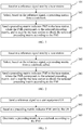
- the method is executed by user equipment UE, and as shown in FIG. 1 , the method includes:
- Step 101 Receive a reference signal sent by a base station.
- the reference signal sent by the base station may include a channel state information reference signal (channel state information Reference Signal, CSI RS), or a demodulation reference signal (demodulation RS, DM RS), or a cell-specific reference signal (cell-specific RS, CRS).
- the user equipment UE may obtain a resource configuration of the reference signal by receiving a notification of the eNB such as RRC (Radio Resource Control, Radio Resource Control) signaling or DCI (Downlink Control Information, downlink control information), or on the basis of a cell identity ID; and obtain the reference signal in a corresponding resource or subframe.
- RRC Radio Resource Control, Radio Resource Control
- DCI Downlink Control Information, downlink control information
- two column vectors (or referred to as beams) can be separately selected from each block matrix X i by using two e i , k in z i,k ; and phase alignment and weighting are performed on the two column vectors (or beams) by using ⁇ i,k and ⁇ i,k e j ⁇ i,k , where the two column vectors selected from X i may separately point to two major multipath transmission directions.
- the block diagonal matrix W 1 is a beam group formed by the block matrices X i that include different beams (or column vectors), and correspondingly, each column of each block matrix Z i included in the matrix Z is used to combine (including phase alignment and weighting) two beams in the block matrix X i , where directions of the two beams may separately point to two major multipath transmission directions. Therefore, for each column of an obtained matrix X i Z i , interference between two major multipath transmission directions can be converted into a wanted signal by using the foregoing structure, thereby significantly improving transmit power corresponding to each column of X i Z i .
- the parameters ⁇ i,k and ⁇ i,k may be equal, and in this case, equal-power combining gains of two beams are obtained.
- One of the parameters ⁇ i,k and ⁇ i,k may be 0, and in this case, selective combining gains of two beams are obtained.
- the parameters ⁇ i,k and ⁇ i,k may also be other quantized values, for example, a value of ⁇ i,k e j ⁇ i,k may be selected from a constellation diagram of modulation such as 16QAM or 64QAM, and in this case, maximum ratio combining gains of two beams are obtained.
- the matrix W 2 is used to select one or column vectors in the matrix W 1 Z and perform weighting combination to form the matrix w .
- the precoding matrix w can further adapt to a sub-band or a short-term characteristic of a channel, and one-layer or multi-layer transmission is formed, thereby improving a transmission rate.
- DFT Discrete Fourier Transform
- Each column of the matrix X i , j in formula (6) may also be selected from columns of a precoding matrix in an LTE R8 system 2-antenna or 4-antenna codebook or in an LTE RIO system 8-antenna codebook.
- each column of the matrix A i,j or the matrix B i,j in formula (11) may be a column vector of the Householder matrix shown in (7), or the DFT matrix shown in (8), or the Hadamard matrix or the rotated Hadamard matrix shown in (9) or (10), or the precoding matrix in the LTE R8 system 2-antenna or 4-antenna codebook or in the LTE R10 system 8-antenna codebook.
- other forms may also be used for the matrix A i,j or the matrix B i,j , which are not described in detail herein.
- the precoding matrix w can adapt to an antenna configuration of the AAS base station, thereby fully using freedom in horizontal and perpendicular directions of an antenna of the AAS base station.
- block matrices X i in formula (6) may be equal to each other, where 1 ⁇ i ⁇ N B ; in this way, relevance between channels can be fully used, and feedback overheads can be further reduced.
- the structure shown in (5) helps select two antenna ports by directly using two e i , k in z i,k , and helps perform phase alignment and weighting on the two antenna ports by using ⁇ i,k e j ⁇ i,k , where the two selected antenna ports may separately align with two major multipath transmission directions.
- An actually deployed antenna port may correspond to a virtual antenna, where each virtual antenna is obtained by performing weighting combination on multiple physical antennas, and virtual antennas may have different beam directions; therefore, in the foregoing precoding structure, different beam directions of the antenna ports can be fully used, and interference between two major multipath transmission directions can be directly converted into a wanted signal, thereby significantly improving a system transmission rate.
- the phase ⁇ i,k in the structure (5) may be selected from the following values: ⁇ i , k ⁇ 0 , 2 ⁇ N , ... , N ⁇ 1 2 ⁇ N where N is a positive integer, for example, N is 2 to the power of n, where n is a positive integer.
- the foregoing block matrices Z i may be equal to each other, where 1 ⁇ i ⁇ N B ; in this way, relevance between channels can be fully used, and feedback overheads can be further reduced.
- the matrix W 2 is used to select or perform weighting combination on a column vector in the matrix W 1 Z to form the matrix w .
- the selecting, based on the reference signal, a precoding matrix from a codebook may include: obtaining, by the user equipment UE based on the reference signal, channel estimation, and selecting the precoding matrix from the codebook according to the channel estimation and based on a predefined rule such as a rule of maximizing a channel capacity or a throughput, where selection, based on a predefined rule, of a precoding matrix is the prior art, and is not described in detail herein.
- a predefined rule such as a rule of maximizing a channel capacity or a throughput
- Step 103 Send a precoding matrix indicator PMI to the base station according to the selected precoding matrix w , where the PMI is used by the base station to obtain the selected precoding matrix W according to the PMI.
- the precoding matrix w is included in a precoding matrix set or a codebook, and the PMI is used to indicate the precoding matrix w selected from the precoding matrix set or the codebook.
- the sending a precoding matrix indicator PMI to the base station includes: sending the precoding matrix indicator PMI to the base station, where the PMI may only include a specific value, and in this case, the PMI directly indicates the precoding matrix w .
- the PMI may only include a specific value, and in this case, the PMI directly indicates the precoding matrix w .
- the PMI may only include a specific value, and in this case, the PMI directly indicates the precoding matrix w .
- the sending a precoding matrix indicator PMI to the base station may also include: sending precoding matrix indicators PMI 1 and PMI 2 to the base station, where the PMI 1 and the PMI 2 are respectively used to indicate the matrix W 1 Z and the matrix W 2 in formula (1), and in this case, the matrix W 1 Z and the matrix W 2 are respectively indicated by the PMI 1 and the PMI 2 in the codebook; or the sending a precoding matrix indicator PMI to the base station may also include: sending a third precoding matrix indicator PMI 3 and a fourth precoding matrix indicator PMI 4 to the base station, where the PMI 3 is used to indicate the matrix W 1 , and the PMI 4 is used to indicate the matrix ZW 2 ; or sending the second precoding matrix indicator PMI 2 , the third precoding matrix indicator PMI 3 , and a fifth precoding matrix indicator PMI 5 to the base station, where the PMI 5 is used to indicate Z
- the precoding matrix indicators PMI 1 and PMI 2 , or PMI 3 and PMI 4 , or PMI 2 , PMI 3 , and PMI 5 have different time domains or frequency domain granularities.
- the sending a precoding matrix indicator PMI to the base station specifically includes:
- the sizes of the foregoing wideband and sub-band may vary with the size of a system bandwidth.
- the wideband may include 50 RBs, and the size of the sub-band may be 6 consecutive RBs; and in a 5 MHz LTE system, the wideband may include 25 RBs, and the size of the sub-band may be 3 consecutive RBs.
- feedback overheads can be further reduced by using time or frequency domain relevance between channels.
- the sending a precoding matrix indicator PMI to the base station may also include: sending a precoding matrix indicator PMI1 i , where 1 ⁇ i ⁇ N B , and the PMI 2 to the base station; PMI i , where 1 ⁇ i ⁇ N B , and the PMI 2 are respectively used to indicate the matrix X i Z i , where 1 ⁇ i ⁇ N B , and the matrix W 2 ; or sending a precoding matrix indicator PMI3i, where 1 ⁇ i ⁇ N B , and the PMI 4 to the base station; PMI3i, where 1 ⁇ i ⁇ N B , is used to indicate X i and the PMI 4 is used to indicate the matrix ZW 2 ; or sending a precoding matrix indicator PMI3i, where 1 ⁇ i ⁇ N B , the PMI 2 , and the PMI 5 to the base station, where the PMI 5 is used to indicate Z .
- the sending a precoding matrix indicator PMI to the base station may be: sending, by the UE, the precoding matrix indicator PMI to the base station through a physical uplink control channel (Physical Uplink Control Channel, PUCCH) or a physical uplink shared channel (Physical Uplink Shared Channel, PUSCH).
- a physical uplink control channel Physical Uplink Control Channel, PUCCH
- a physical uplink shared channel Physical Uplink Shared Channel, PUSCH
- the sending a precoding matrix indicator PMI to the base station may be: separately sending, by the UE to the base station by using different subframes or in different periods, the PMI 1 and the PMI 2 , or the PMI 3 and the PMI 4 , or the PMI 2 , the PMI 3 , and the PMI 5 , or the PMI1 i , where 1 ⁇ i ⁇ N B , and the PMI 2 , or the PMI3,i and the PMI 4 , or the PMI3i, where 1 ⁇ i ⁇ N B , the PMI 2 , and the PMI 5 , or the PMI5i, where 1 ⁇ i ⁇ N B /2, and the PMI 2 .
- the sending a precoding matrix indicator PMI to the base station may also be: separately sending, by the UE to the base station according to different sub-bands or sub-band widths in a frequency domain, the PMI 1 and the PMI 2 , or the PMI 3 and the PMI 4 , or the PMI 2 , the PMI 3 , and the PMI 5 , or the PMI1 i , where 1 ⁇ i ⁇ N B , and the PMI 2 , or the PMI3,i and the PMI 4 , or the PMI3i, where 1 ⁇ i ⁇ N B , the PMI 2 , and the PMI 5 , or the PMI5i, where 1 ⁇ i ⁇ N B /2, and the PMI 2 .
- multiple block matrices X i may separately correspond to antenna groups of different polarizations or different locations; therefore, the precoding matrix can match multiple antenna deployments or configurations.
- the foregoing codebook structure can significantly improve performance of MIMO, especially MU-MIMO.
- one or more PMIs are fed back based on a subset, to indicate the precoding matrix; therefore, time/frequency domain/space relevance between channels is fully used, thereby significantly reducing feedback overheads.
- the selecting, based on the reference signal, a precoding matrix from a codebook is specifically: 202: Select, based on the reference signal, the precoding matrix from a codebook subset.
- the codebook subset may be a predefined codebook subset; or may be a codebook subset as follows: the codebook subset is reported by the UE to the base station eNB, determined by the base station eNB based on a report of the UE, and then told by the base station to the UE; or may be a codebook subset that is determined and reported by the UE, for example, a recently reported codebook subset.
- codebook subset and another codebook subset share at least one same matrix subset of the following matrix subsets: subsets of a matrix W 1 , a matrix W 1 Z , a matrix W 2 , a matrix ZW 2 , and a matrix Z .
- the precoding matrix is selected based on the codebook subset, which can further reduce feedback overheads and implementation complexity.
- the codebook subsets share a same subset of the matrix W 1 , or the matrix W 1 Z , or the matrix W 2 , or the matrix ZW 2 , or the matrix Z, and therefore, the codebook subsets overlap with each other, which can overcome an edge effect of quantization of channel state information.
- the block matrices X i of the block diagonal matrix W 1 may be unequal, or may be equal. If the block diagonal matrix W 1 has multiple equal block matrices, for example, equal block matrices may appear in pairs, feedback overheads can be further reduced.
- the three matrices W 1 , Z , and W 2 included in the precoding matrix w that is selected, based on the reference signal, from the codebook may further be multiplied by a scale factor, so as to implement power normalization or power balancing.
- the codebook may further include other precoding matrices, so as to meet requirements of other scenarios, which is not limited herein.
- This embodiment of the present invention provides the method for reporting channel state information.
- two column vectors (or referred to as beams) can be separately selected from each block matrix X i by using the structure of the matrix Z ; and phase alignment and weighting are performed on the two column vectors (or beams), where the two column vectors selected from X i may separately point to two major multipath transmission directions. Therefore, by using the foregoing structure, for each column of an obtained matrix X i Z i , interference between two major multipath transmission directions can be converted into a wanted signal, and combining gains are obtained, thereby improving system transmission reliability and a system transmission throughput.
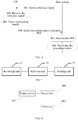
- This embodiment of the present invention further provides a method for reporting channel state information.
- the method is executed by a base station, and as shown in FIG. 3 , the method includes:
- the codebook may further include other precoding matrices, so as to meet requirements of other scenarios, which is not limited herein.
- two column vectors (or referred to as beams) can be separately selected from each block matrix X i by using the structure of the matrix Z ; and phase alignment and weighting are performed on the two column vectors (or beams), where the two column vectors selected from X i may separately point to two major multipath transmission directions. Therefore, by using the foregoing structure, for each column of an obtained matrix X i Z i , interference between two major multipath transmission directions can be converted into a wanted signal, and combining gains are obtained, thereby improving system transmission reliability and a system transmission throughput.
- the following describes in detail interaction between devices for implementing a method for reporting channel state information provided in this embodiment of the present invention, and as shown in FIG. 4 , the method includes:
- two column vectors (or referred to as beams) can be separately selected from each block matrix X i by using the foregoing structure; and phase alignment and weighting are performed on the two column vectors (or beams), where the two column vectors selected from X i may separately point to two major multipath transmission directions. Therefore, by using the foregoing structure, for each column of an obtained matrix X i Z i , interference between two major multipath transmission directions can be converted into a wanted signal, and combining gains are obtained, thereby improving system transmission reliability and a system transmission throughput.
- the user equipment includes: a receiving unit 51, a selection unit 52, and a sending unit 53.
- the receiving unit 51 is configured to receive a reference signal sent by a base station.
- the sending unit 53 is configured to send a precoding matrix indicator PMI to the base station, where the PMI corresponds to the selected precoding matrix, and is used by the base station to obtain the selected precoding matrix w according to the PMI.
- the selection unit 52 is specifically configured to select, based on the reference signal, the precoding matrix from a codebook subset, where the codebook subset is a subset predefined, or notified by the base station, or determined by the user equipment.
- the codebook subsets share at least one same matrix subset of the following matrix subsets: subsets of a matrix W 1 , a matrix W 1 Z, a matrix W 2 , a matrix ZW 2 , and a matrix Z .
- the sending unit 53 may be specifically configured to send a first precoding matrix indicator PMI 1 and a second precoding matrix indicator PMI 2 to the base station, where the PMI 1 is used to indicate the matrix W 1 Z , and the PMI 2 is used to indicate the matrix W 2 ; or send a third precoding matrix indicator PMI 3 and a fourth precoding matrix indicator PMI 4 to the base station, where the PMI 3 is used to indicate the matrix W 1 , and the PMI 4 is used to indicate the matrix ZW 2 ; or send the second precoding matrix indicator PMI 2 , the third precoding matrix indicator PMI 3 , and a fifth precoding matrix indicator PMI 5 to the base station, where the PMI 5 is used to indicate Z
- the sending unit 53 may be specifically configured to send the PMI 1 to the base station according to a first period; and send the PMI 2 to the base station according to a second period, where the first period is greater than the second period; or send the PMI 3 to the base station according to a third period; and send the PMI 4 to the base station according to a fourth period, where the third period is greater than the fourth period; or send the PMI 2 to the base station according to a second period; send the PMI 3 to the base station according to a third period; and send the PMI 5 to the base station according to a fifth period, where the third period is less than the second period and the fifth period.
- the sending unit 53 may further be specifically configured to send the PMI 1 to the base station according to a first frequency domain granularity; and send the PMI 2 to the base station according to a second frequency domain granularity, where the first frequency domain granularity is greater than the second frequency domain granularity, for example, send a wideband PMI 1 and a sub-band PMI 2 to the base station; or send the PMI 3 to the base station according to a third frequency domain granularity; and send the PMI 4 to the base station according to a fourth frequency domain granularity, where the third frequency domain granularity is greater than the fourth frequency domain granularity, for example, send a wideband PMI 3 and a sub-band PMI 4 to the base station; or send the PMI 2 to the base station according to a second frequency domain granularity; send the PMI 3 to the base station according to a third frequency domain granularity; and send the PMI 5 to the base station according to a fifth frequency domain granularity,
- the sizes of the foregoing wideband and sub-band may vary with the size of a system bandwidth.
- the wideband may include 50 physical resource blocks RBs, and the size of the sub-band may be 6 consecutive RBs; and in a 5 MHz LTE system, the wideband may include 25 RBs, and the size of the sub-band may be 3 consecutive RBs.
- the block matrix X i [ X i ,1 X i ,2 ], where each column of the matrix X i,j is selected from columns of a Householder matrix, a discrete Fourier transform matrix, a Hadamard matrix, a rotated Hadamard matrix, or a precoding matrix in an LTE R8 system 2-antenna or 4-antenna codebook or in an LTE RIO system 8-antenna codebook.
- columns of the matrix X i ,1 and the matrix X i, 2 are column vectors of a Householder matrix, a discrete Fourier transform matrix, a Hadamard matrix, a rotated Hadamard matrix, or a precoding matrix in an LTE R8 system 2-antenna or 4-antenna codebook or in an LTE R10 system 8-antenna codebook.
- W 1 is an identity matrix.
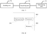
- the user equipment includes: a transceiver 601, a memory 602, and a processor 603.
- the user equipment may further include common-purpose components such as an antenna and an input output apparatus, which is not limited herein in this embodiment of the present invention.
- the memory 602 stores a set of program code
- the selecting, based on the reference signal, a precoding matrix from a codebook specifically includes: selecting, based on the reference signal, the precoding matrix from a codebook subset, where the codebook subset is a subset predefined, or notified by the base station, or reported by the user equipment.
- the codebook subsets share at least one same matrix subset of the following matrix subsets: subsets of a matrix W 1 , a matrix W 1 Z , a matrix W 2 , a matrix ZW 2 , and a matrix Z .
- the sending a precoding matrix indicator PMI to the base station by using the transceiver 61 specifically includes:
- the sending a precoding matrix indicator PMI to the base station by using the transceiver 61 specifically includes:
- the sending a precoding matrix indicator PMI to the base station by using the transceiver 61 specifically includes:
- the sizes of the foregoing wideband and sub-band may vary with the size of a system bandwidth.
- the wideband may include 50 physical resource blocks RBs, and the size of the sub-band may be 6 consecutive RBs; and in a 5 MHz LTE system, the wideband may include 25 RBs, and the size of the sub-band may be 3 consecutive RBs.
- the block matrix X i [ X i ,1 X i ,2 ], where each column of the matrix X i , j is selected from columns of a Householder matrix, a discrete Fourier transform matrix, a Hadamard matrix, a rotated Hadamard matrix, or a precoding matrix in an LTE R8 system 2-antenna or 4-antenna codebook or in an LTE RIO system 8-antenna codebook.
- columns of the matrix X i ,1 and the matrix X i ,2 are column vectors of a Householder matrix, a discrete Fourier transform matrix, a Hadamard matrix, a rotated Hadamard matrix, or a precoding matrix in an LTE R8 system 2-antenna or 4-antenna codebook or in an LTE R10 system 8-antenna codebook.
- W 1 is an identity matrix.
- the codebook may further include other precoding matrices, so as to meet requirements of other scenarios, which is not limited herein.
- two column vectors (or referred to as beams) can be separately selected from each block matrix X i by using the foregoing structure; and phase alignment and weighting are performed on the two column vectors (or beams), where the two column vectors selected from X i may separately point to two major multipath transmission directions. Therefore, by using the foregoing structure, for each column of an obtained matrix X i Z i , interference between two major multipath transmission directions can be converted into a wanted signal, and combining gains are obtained, thereby improving system transmission reliability and a system transmission throughput.
- the base station includes: a sending unit 71, a receiving unit 72, and a determining unit 73.
- the sending unit 71 is configured to send a reference signal to user equipment UE.
- the receiving unit 72 is configured to receive a precoding matrix indicator PMI sent by the UE.
- the determining unit 73 is specifically configured to determine the precoding matrix in a codebook subset according to the PMI, where the codebook subset is a subset predefined, or reported by the user equipment, or determined by the base station.
- the codebook subsets share at least one same matrix subset of the following matrix subsets: subsets of a matrix W 1 , a matrix W 1 Z , a matrix W 2 , a matrix ZW 2 , and a matrix Z.
- the receiving unit 72 is specifically configured to:
- the receiving unit 72 is specifically configured to:
- the receiving unit 72 is specifically configured to:
- the sizes of the foregoing wideband and sub-band may vary with the size of a system bandwidth.
- the wideband may include 50 physical resource blocks RBs, and the size of the sub-band may be 6 consecutive RBs; and in a 5 MHz LTE system, the wideband may include 25 RBs, and the size of the sub-band may be 3 consecutive RBs.
- the block matrix X i [ X i ,1 X i ,2 ], where each column of the matrix X i , j is selected from columns of a Householder matrix, a discrete Fourier transform matrix, a Hadamard matrix, a rotated Hadamard matrix, or a precoding matrix in an LTE R8 system 2-antenna or 4-antenna codebook or in an LTE RIO system 8-antenna codebook.
- each column of the matrix X i , j is separately selected from columns of different Householder matrices, different discrete Fourier transform matrices, different Hadamard matrices, different rotated Hadamard matrices, or different precoding matrices in an LTE R8 system 2-antenna or 4-antenna codebook or in an LTE R10 system 8-antenna codebook.
- columns of the matrix X i ,1 and the matrix X i ,2 are column vectors of a Householder matrix, a discrete Fourier transform matrix, a Hadamard matrix, a rotated Hadamard matrix, or a precoding matrix in an LTE R8 system 2-antenna or 4-antenna codebook or in an LTE R10 system 8-antenna codebook.
- W 1 is an identity matrix.
- the base station includes: a transceiver 801, a memory 802, and a processor 803.
- the base station may further include common-purpose components such as an antenna and an input/output apparatus, which is not limited herein in this embodiment of the present invention.
- the memory 802 stores a set of program code
- the determining a precoding matrix w in a codebook according to the PMI specifically includes: determining the precoding matrix in a codebook subset according to the PMI, where the codebook subset is a subset predefined, or reported by the user equipment, or determined by the base station.
- the codebook subsets share at least one same matrix subset of the following matrix subsets: subsets of a matrix W 1 , a matrix W 1 Z , a matrix W 2 , a matrix ZW 2 , and a matrix Z.
- the receiving the PMI by using the transceiver 81 may specifically include: receiving a first precoding matrix indicator PMI 1 and a second precoding matrix indicator PMI 2 that are sent by the UE, where the PMI 1 is used to indicate the matrix W 1 Z , and the PMI 2 is used to indicate the matrix W 2 ; or receiving a third precoding matrix indicator PMI 3 and a fourth precoding matrix indicator PMI 4 that are sent by the UE, where the PMI 3 is used to indicate the matrix W 1 , and the PMI 4 is used to indicate the matrix ZW 2 ; or receiving the second precoding matrix indicator PMI 2 , the third precoding matrix indicator PMI 3 , and a fifth precoding matrix indicator PMI 5 that are sent by the UE, where the PMI 5 is used to indicate Z.
- the receiving the PMI by using the transceiver 81 may specifically include: receiving, according to a first period, the PMI 1 sent by the UE; and receiving, according to a second period, the PMI 2 sent by the UE, where the first period is greater than the second period; or receiving, according to a third period, the PMI 3 sent by the UE; and receiving, according to a fourth period, the PMI 4 sent by the UE, where the third period is greater than the fourth period; or receiving, according to a second period, the PMI 2 sent by the UE; receiving, according to a third period, the PMI 3 sent by the UE; and receiving, according to a fifth period, the PMI 5 sent by the UE, where the third period is less than the second period and the fifth period.
- the receiving the PMI by using the transceiver 81 may further specifically include: receiving, according to a first frequency domain granularity, the PMI 1 sent by the UE; and receiving, according to a second frequency domain granularity, the PMI 2 sent by the UE, where the first frequency domain granularity is greater than the second frequency domain granularity, for example, receiving a wideband PMI 1 and a sub-band PMI 2 that are sent by the UE; or receiving, according to a third frequency domain granularity, the PMI 3 sent by the UE; and receiving, according to a fourth frequency domain granularity, the PMI 4 sent by the UE, where the third frequency domain granularity is greater than the fourth frequency domain granularity, for example, receiving a wideband PMI 3 and a sub-band PMI 4 that are sent by the UE; or receiving, according to a second frequency domain granularity, the PMI 2 sent by the UE; receiving, according to a third frequency domain granularity
- the sizes of the foregoing wideband and sub-band may vary with the size of a system bandwidth.
- the wideband may include 50 physical resource blocks RBs, and the size of the sub-band may be 6 consecutive RBs; and in a 5 MHz LTE system, the wideband may include 25 RBs, and the size of the sub-band may be 3 consecutive RBs.
- the block matrix X i [ X i ,1 X i ,2 ], where each column of the matrix X i,j is selected from columns of a Householder matrix, a discrete Fourier transform matrix, a Hadamard matrix, a rotated Hadamard matrix, or a precoding matrix in an LTE R8 system 2-antenna or 4-antenna codebook or in an LTE RIO system 8-antenna codebook.
- each column of the matrix X i,j is separately selected from columns of different Householder matrices, different discrete Fourier transform matrices, different Hadamard matrices, different rotated Hadamard matrices, or different precoding matrices in an LTE R8 system 2-antenna or 4-antenna codebook or in an LTE RIO system 8-antenna codebook.
- columns of the matrix X i ,1 and the matrix X i ,2 are column vectors of a Householder matrix, a discrete Fourier transform matrix, a Hadamard matrix, a rotated Hadamard matrix, or a precoding matrix in an LTE R8 system 2-antenna or 4-antenna codebook or in an LTE RIO system 8-antenna codebook.
- W 1 is an identity matrix.
- the codebook may further include other precoding matrices, so as to meet requirements of other scenarios, which is not limited herein.
- two column vectors (or referred to as beams) can be separately selected from each block matrix X i by using the foregoing structure; and phase alignment and weighting are performed on the two column vectors (or beams), where the two column vectors selected from X i may separately point to two major multipath transmission directions. Therefore, by using the foregoing structure, for each column of an obtained matrix X i Z i , interference between two major multipath transmission directions can be converted into a wanted signal, and combining gains are obtained, thereby improving system transmission reliability and a system transmission throughput.
- the disclosed system, apparatus, and method may be implemented in other manners.
- the described apparatus embodiment is merely exemplary.
- the module or unit division is merely logical function division and may be other division in actual implementation.
- a plurality of units or components may be combined or integrated into another system, or some features may be ignored or not performed.
- the displayed or discussed mutual couplings or direct couplings or communication connections may be implemented through some interfaces.
- the indirect couplings or communication connections between the apparatuses or units may be implemented in electronic, mechanical, or other forms.
- the units described as separate parts may or may not be physically separate, and parts displayed as units may or may not be physical units, may be located in one position, or may be distributed on a plurality of network units. Some or all of the units may be selected according to actual needs to achieve the objectives of the solutions of the embodiments.
- functional units in the embodiments of the present invention may be integrated into one processing unit, or each of the units may exist alone physically, or two or more units are integrated into one unit.
- the integrated unit may be implemented in a form of hardware, or may be implemented in a form of a software functional unit.
- the integrated unit When the integrated unit is implemented in the form of a software functional unit and sold or used as an independent product, the integrated unit may be stored in a computer-readable storage medium. Based on such an understanding, the technical solutions of the present invention essentially, or the part contributing to the prior art, or all or some of the technical solutions may be implemented in the form of a software product.
- the software product is stored in a storage medium and includes several instructions for instructing a computer device (which may be a personal computer, a server, or a network device) or a processor to perform all or some of the steps of the methods described in the embodiments of the present invention.
- the foregoing storage medium includes: any medium that can store program code, such as a USB flash drive, a removable hard disk, a read-only memory (ROM, Read-Only Memory), a random access memory (RAM, Random Access Memory), a magnetic disk, or an optical disc.
- program code such as a USB flash drive, a removable hard disk, a read-only memory (ROM, Read-Only Memory), a random access memory (RAM, Random Access Memory), a magnetic disk, or an optical disc.
Landscapes
- Engineering & Computer Science (AREA)
- Computer Networks & Wireless Communication (AREA)
- Signal Processing (AREA)
- Physics & Mathematics (AREA)
- Mathematical Physics (AREA)
- Mobile Radio Communication Systems (AREA)
- Radio Transmission System (AREA)
Priority Applications (2)
| Application Number | Priority Date | Filing Date | Title |
|---|---|---|---|
| EP19191870.5A EP3661069B1 (fr) | 2013-04-15 | 2013-04-15 | Procédé de remontée d'informations d'état de canal, équipement utilisateur et station de base |
| PL19191870T PL3661069T3 (pl) | 2013-04-15 | 2013-04-15 | Sposób raportowania informacji o stanie kanału, sprzęcie użytkownika i stacji bazowej |
Applications Claiming Priority (4)
| Application Number | Priority Date | Filing Date | Title |
|---|---|---|---|
| EP19191870.5A EP3661069B1 (fr) | 2013-04-15 | 2013-04-15 | Procédé de remontée d'informations d'état de canal, équipement utilisateur et station de base |
| EP17187683.2A EP3306827B1 (fr) | 2013-04-15 | 2013-04-15 | Procédé de remontée d'informations d'état de canal, équipement utilisateur et station de base |
| EP13882430.5A EP2985921B1 (fr) | 2013-04-15 | 2013-04-15 | Procédé permettant de rapporter des informations d'état de canal, dispositif d'utilisateur et station de base |
| PCT/CN2013/074214 WO2014169421A1 (fr) | 2013-04-15 | 2013-04-15 | Procédé permettant de rapporter des informations d'état de canal, dispositif d'utilisateur et station de base |
Related Parent Applications (2)
| Application Number | Title | Priority Date | Filing Date |
|---|---|---|---|
| EP17187683.2A Division EP3306827B1 (fr) | 2013-04-15 | 2013-04-15 | Procédé de remontée d'informations d'état de canal, équipement utilisateur et station de base |
| EP13882430.5A Division EP2985921B1 (fr) | 2013-04-15 | 2013-04-15 | Procédé permettant de rapporter des informations d'état de canal, dispositif d'utilisateur et station de base |
Publications (2)
| Publication Number | Publication Date |
|---|---|
| EP3661069A1 true EP3661069A1 (fr) | 2020-06-03 |
| EP3661069B1 EP3661069B1 (fr) | 2021-08-18 |
Family
ID=51730659
Family Applications (3)
| Application Number | Title | Priority Date | Filing Date |
|---|---|---|---|
| EP19191870.5A Active EP3661069B1 (fr) | 2013-04-15 | 2013-04-15 | Procédé de remontée d'informations d'état de canal, équipement utilisateur et station de base |
| EP17187683.2A Active EP3306827B1 (fr) | 2013-04-15 | 2013-04-15 | Procédé de remontée d'informations d'état de canal, équipement utilisateur et station de base |
| EP13882430.5A Active EP2985921B1 (fr) | 2013-04-15 | 2013-04-15 | Procédé permettant de rapporter des informations d'état de canal, dispositif d'utilisateur et station de base |
Family Applications After (2)
| Application Number | Title | Priority Date | Filing Date |
|---|---|---|---|
| EP17187683.2A Active EP3306827B1 (fr) | 2013-04-15 | 2013-04-15 | Procédé de remontée d'informations d'état de canal, équipement utilisateur et station de base |
| EP13882430.5A Active EP2985921B1 (fr) | 2013-04-15 | 2013-04-15 | Procédé permettant de rapporter des informations d'état de canal, dispositif d'utilisateur et station de base |
Country Status (5)
| Country | Link |
|---|---|
| US (6) | US9608708B2 (fr) |
| EP (3) | EP3661069B1 (fr) |
| CN (3) | CN107872261B (fr) |
| PL (1) | PL3661069T3 (fr) |
| WO (1) | WO2014169421A1 (fr) |
Families Citing this family (27)
| Publication number | Priority date | Publication date | Assignee | Title |
|---|---|---|---|---|
| CN104065448B (zh) * | 2013-03-22 | 2017-11-14 | 电信科学技术研究院 | 一种确定预编码矩阵的方法、系统和设备 |
| US9774430B2 (en) * | 2014-05-22 | 2017-09-26 | Lg Electronics Inc. | Method and apparatus for channel estimation in wireless communication system |
| WO2016111427A1 (fr) * | 2015-01-05 | 2016-07-14 | 엘지전자 주식회사 | Procédé de configuration d'informations d'état de canal au moyen des caractéristiques de polarisation d'une antenne dans un système de communication sans fil, et dispositif à cet effet |
| EP3334055A4 (fr) * | 2015-08-24 | 2018-09-26 | Huawei Technologies Co., Ltd. | Procédé et appareil d'envoi d'informations de précodage et de rétroaction |
| CN108370265B (zh) * | 2015-12-29 | 2021-09-07 | 华为技术有限公司 | 一种确定预编码矩阵的方法及装置 |
| WO2017168349A1 (fr) | 2016-03-31 | 2017-10-05 | Telefonaktiebolaget Lm Ericsson (Publ) | Procédés et dispositifs pour déterminer des paramètres de précodeur dans un réseau de communication sans fil |
| CN110034797B (zh) * | 2016-04-01 | 2020-06-26 | 华为技术有限公司 | 一种预编码矩阵指示的反馈方法及装置 |
| CN107370525B (zh) * | 2016-05-12 | 2021-03-30 | 华为技术有限公司 | 用于信道状态信息反馈的方法、基站、终端设备及系统 |
| EP3446416B1 (fr) | 2016-05-13 | 2020-11-04 | Huawei Technologies Co., Ltd. | Précodage et acquisition d'informations d'état de canal pour des transmissions de multiples flux dans des systèmes mimo massifs |
| CN110545130B (zh) * | 2016-11-04 | 2020-08-07 | 华为技术有限公司 | 信道状态信息接收方法、用户设备和网络设备 |
| CN108288987B (zh) * | 2017-01-07 | 2021-10-01 | 华为技术有限公司 | 一种发射分集的方法、终端和基站 |
| CN110140313B (zh) * | 2017-01-25 | 2020-09-08 | 华为技术有限公司 | 信道状态信息的传输方法、接入网设备和终端设备 |
| CN108631838A (zh) * | 2017-03-24 | 2018-10-09 | 华为技术有限公司 | 信令的发送方法,装置和系统 |
| CN108631999B (zh) | 2017-03-25 | 2021-07-09 | 华为技术有限公司 | 信令的发送方法,装置和系统 |
| EP3619817B1 (fr) * | 2017-05-04 | 2021-09-29 | Telefonaktiebolaget LM Ericsson (PUBL) | Formation de faisceau basée sur des faisceaux combinés |
| EP3697128B1 (fr) * | 2017-11-17 | 2024-04-03 | Huawei Technologies Co., Ltd. | Procédé de rétroaction d'informations d'état de canal, dispositif de communication et système |
| CN112203887B (zh) | 2018-04-13 | 2024-09-17 | 贝洱海拉温控系统有限公司 | 特别是用于运载工具的显示设备 |
| CN111181705B (zh) * | 2018-11-15 | 2022-07-15 | 维沃移动通信有限公司 | 上行传输方法、指示方法、终端及网络设备 |
| CN111435848B (zh) * | 2019-01-11 | 2022-05-31 | 华为技术有限公司 | 指示和确定预编码向量的方法以及通信装置 |
| US10924240B2 (en) * | 2019-03-26 | 2021-02-16 | Qualcomm Incorporated | Sounding reference signal transmission to indicate a virtual antenna port |
| CN114287139B (zh) * | 2019-08-23 | 2025-03-11 | 株式会社Ntt都科摩 | 终端、无线通信方法、基站以及系统 |
| JP2022549600A (ja) | 2019-09-24 | 2022-11-28 | ベーア-ヘラー サーモコントロール ゲーエムベーハー | 光学式近接センサシステム内蔵の表示装置 |
| WO2021081129A1 (fr) | 2019-10-21 | 2021-04-29 | Illumina, Inc. | Efficacité de calcul accrue pour la microscopie à éclairage structuré |
| KR20260049306A (ko) * | 2019-10-29 | 2026-04-13 | 노키아 테크놀로지스 오와이 | Pmi 보고 및 사용을 위한 조합 인디케이터에 대한 윈도우 fd 기반의 매핑 |
| US11876654B2 (en) * | 2020-04-22 | 2024-01-16 | Qualcomm Incorporated | Methods and apparatus for unified codebooks for orthogonal sequence transmission |
| CN113938169B (zh) | 2020-06-29 | 2023-09-22 | 华为技术有限公司 | 预编码矩阵确定方法及装置 |
| CN117441295A (zh) * | 2021-06-21 | 2024-01-23 | 联发科技(新加坡)私人有限公司 | 用于上行链路通信的高空间分辨率mimo预编码 |
Citations (4)
| Publication number | Priority date | Publication date | Assignee | Title |
|---|---|---|---|---|
| WO2011126160A1 (fr) * | 2010-04-05 | 2011-10-13 | Pantech Co.,Ltd. | Procédé de précodage, procédé d'information de canal de retour, terminal mobile et station de base dans un système de communications sans fil |
| EP2555445A1 (fr) * | 2011-08-03 | 2013-02-06 | Alcatel Lucent | Procédé pour utiliser un émetteur et émetteur |
| WO2013024350A2 (fr) * | 2011-08-15 | 2013-02-21 | Alcatel Lucent | Procédés et appareils pour mesure de canal et retour d'informations d'un réseau d'antennes multidimensionnel |
| WO2013032271A2 (fr) * | 2011-09-02 | 2013-03-07 | 엘지전자 주식회사 | Procédé et appareil de transmission d'informations d'état de canal dans un système de communication sans fil |
Family Cites Families (9)
| Publication number | Priority date | Publication date | Assignee | Title |
|---|---|---|---|---|
| WO2008133582A2 (fr) * | 2007-04-30 | 2008-11-06 | Telefonaktiebolaget L M Ericsson (Publ) | Procédé et agencement pour adapter une émission à multiples antennes |
| EP2660991B1 (fr) | 2009-01-07 | 2020-07-29 | Sun Patent Trust | Appareil et procédé de communication sans fil |
| CN101826945B (zh) * | 2010-04-05 | 2015-08-12 | 中兴通讯股份有限公司 | 信道信息的发送方法和装置 |
| CN101931513B (zh) * | 2010-05-18 | 2016-06-15 | 中兴通讯股份有限公司 | 信道状态信息的反馈方法及终端 |
| CN101860420B (zh) * | 2010-06-18 | 2015-08-12 | 中兴通讯股份有限公司 | 一种信道信息获取方法及系统 |
| US8781018B2 (en) * | 2011-04-25 | 2014-07-15 | Texas Instruments Incorporated | Six transmit antenna codebook design |
| US9077402B2 (en) * | 2011-11-07 | 2015-07-07 | Lg Electronics Inc. | Method for feeding back codebook-based precoding matrix information in wireless communication system and device therefor |
| CN102412885B (zh) * | 2011-11-25 | 2015-05-06 | 西安电子科技大学 | Lte中的三维波束赋形方法 |
| ES2756449T3 (es) * | 2012-06-14 | 2020-04-27 | Huawei Tech Co Ltd | Método, equipo de usuario y nodo evolucionado de estación base para determinar un indicador de matriz de precodificación |
-
2013
- 2013-04-15 PL PL19191870T patent/PL3661069T3/pl unknown
- 2013-04-15 CN CN201711130973.7A patent/CN107872261B/zh active Active
- 2013-04-15 CN CN201380023172.4A patent/CN104541456B/zh active Active
- 2013-04-15 EP EP19191870.5A patent/EP3661069B1/fr active Active
- 2013-04-15 CN CN201711132866.8A patent/CN107888269B/zh active Active
- 2013-04-15 EP EP17187683.2A patent/EP3306827B1/fr active Active
- 2013-04-15 WO PCT/CN2013/074214 patent/WO2014169421A1/fr not_active Ceased
- 2013-04-15 EP EP13882430.5A patent/EP2985921B1/fr active Active
-
2015
- 2015-10-14 US US14/883,334 patent/US9608708B2/en active Active
-
2017
- 2017-02-22 US US15/439,686 patent/US9838097B2/en active Active
- 2017-11-09 US US15/808,318 patent/US10063296B2/en active Active
-
2018
- 2018-08-08 US US16/058,636 patent/US10447356B2/en active Active
-
2019
- 2019-10-07 US US16/594,646 patent/US10735063B2/en active Active
-
2020
- 2020-07-23 US US16/937,561 patent/US11184062B2/en active Active
Patent Citations (5)
| Publication number | Priority date | Publication date | Assignee | Title |
|---|---|---|---|---|
| WO2011126160A1 (fr) * | 2010-04-05 | 2011-10-13 | Pantech Co.,Ltd. | Procédé de précodage, procédé d'information de canal de retour, terminal mobile et station de base dans un système de communications sans fil |
| EP2555445A1 (fr) * | 2011-08-03 | 2013-02-06 | Alcatel Lucent | Procédé pour utiliser un émetteur et émetteur |
| WO2013024350A2 (fr) * | 2011-08-15 | 2013-02-21 | Alcatel Lucent | Procédés et appareils pour mesure de canal et retour d'informations d'un réseau d'antennes multidimensionnel |
| WO2013032271A2 (fr) * | 2011-09-02 | 2013-03-07 | 엘지전자 주식회사 | Procédé et appareil de transmission d'informations d'état de canal dans un système de communication sans fil |
| US20140227987A1 (en) * | 2011-09-02 | 2014-08-14 | Lg Electronics Inc. | Method and apparatus for transmitting channel state information in a wireless communication system |
Non-Patent Citations (2)
| Title |
|---|
| ALCATEL-LUCENT SHANGHAI BELL ET AL: "Considerations on CSI feedback enhancements for high-priority antenna configurations", 3GPP DRAFT; R1-112420 CONSIDERATIONS ON CSI FEEDBACK ENHANCEMENTS FOR HIGH-PRIORITY ANTENNA CONFIGURATIONS_CLEAN, 3RD GENERATION PARTNERSHIP PROJECT (3GPP), MOBILE COMPETENCE CENTRE ; 650, ROUTE DES LUCIOLES ; F-06921 SOPHIA-ANTIPOLIS CEDEX ; FRANCE, vol. RAN WG1, no. Athens, Greece; 20110822, 18 August 2011 (2011-08-18), XP050537814 * |
| SAMSUNG: "Downlink MIMO Enhancements for Release-12", vol. RAN WG1, no. New Orleans; 20121112 - 20121116, 3 November 2012 (2012-11-03), XP050662870, Retrieved from the Internet <URL:http://www.3gpp.org/ftp/tsg_ran/WG1_RL1/TSGR1_71/Docs/> [retrieved on 20121103] * |
Also Published As
| Publication number | Publication date |
|---|---|
| US9838097B2 (en) | 2017-12-05 |
| EP3306827B1 (fr) | 2019-09-11 |
| US10447356B2 (en) | 2019-10-15 |
| EP3661069B1 (fr) | 2021-08-18 |
| US20180069609A1 (en) | 2018-03-08 |
| CN107872261B (zh) | 2023-04-11 |
| EP2985921B1 (fr) | 2017-08-30 |
| EP2985921A1 (fr) | 2016-02-17 |
| CN104541456A (zh) | 2015-04-22 |
| US10063296B2 (en) | 2018-08-28 |
| US11184062B2 (en) | 2021-11-23 |
| US20170163321A1 (en) | 2017-06-08 |
| EP2985921A4 (fr) | 2016-02-24 |
| WO2014169421A1 (fr) | 2014-10-23 |
| CN104541456B (zh) | 2017-11-28 |
| US20200044700A1 (en) | 2020-02-06 |
| PL3661069T3 (pl) | 2022-01-17 |
| US20200358489A1 (en) | 2020-11-12 |
| US20180351616A1 (en) | 2018-12-06 |
| EP3306827A1 (fr) | 2018-04-11 |
| US10735063B2 (en) | 2020-08-04 |
| CN107888269B (zh) | 2022-12-13 |
| US9608708B2 (en) | 2017-03-28 |
| CN107888269A (zh) | 2018-04-06 |
| US20160036507A1 (en) | 2016-02-04 |
| CN107872261A (zh) | 2018-04-03 |
Similar Documents
| Publication | Publication Date | Title |
|---|---|---|
| US11184062B2 (en) | Method for reporting channel state information, user equipment, and base station | |
| US11431392B2 (en) | Method for feeding backchannel state information, user equipment, and base station | |
| US10122427B2 (en) | Method for determining precoding matrix indicator, user equipment, and base station evolved NodeB | |
| EP3160056B1 (fr) | Procédé et dispositif de réception et de renvoi d'informations d'état de canal | |
| JP6267336B2 (ja) | プリコーディングマトリクス指標を決定する方法、受信装置、および送信装置 | |
| US10516450B2 (en) | Method, system, and device for transmitting coding instruction information and for determining pre-coding matrix | |
| CN109075904B (zh) | 一种预编码矩阵指示的反馈方法及装置 | |
| US20180191410A1 (en) | Subset of w2 method and apparatus for sending precoding information and feeding back precoding information | |
| CN107733493A (zh) | 用于确定预编码矩阵的方法和装置 | |
| EP3480982B1 (fr) | Appareil, procédé et système destinés à la transmission d'informations de canal | |
| US10567054B2 (en) | Channel state information sending method and receiving method, apparatus, and system | |
| US20230362702A1 (en) | Method and apparatus for csi reporting in multi-trp scenarios | |
| JP2018074605A (ja) | プリコーディングマトリクス指標を決定する方法、受信装置、および送信装置 |
Legal Events
| Date | Code | Title | Description |
|---|---|---|---|
| PUAI | Public reference made under article 153(3) epc to a published international application that has entered the european phase |
Free format text: ORIGINAL CODE: 0009012 |
|
| STAA | Information on the status of an ep patent application or granted ep patent |
Free format text: STATUS: THE APPLICATION HAS BEEN PUBLISHED |
|
| AC | Divisional application: reference to earlier application |
Ref document number: 2985921 Country of ref document: EP Kind code of ref document: P Ref document number: 3306827 Country of ref document: EP Kind code of ref document: P |
|
| AK | Designated contracting states |
Kind code of ref document: A1 Designated state(s): AL AT BE BG CH CY CZ DE DK EE ES FI FR GB GR HR HU IE IS IT LI LT LU LV MC MK MT NL NO PL PT RO RS SE SI SK SM TR |
|
| STAA | Information on the status of an ep patent application or granted ep patent |
Free format text: STATUS: REQUEST FOR EXAMINATION WAS MADE |
|
| 17P | Request for examination filed |
Effective date: 20200925 |
|
| RBV | Designated contracting states (corrected) |
Designated state(s): AL AT BE BG CH CY CZ DE DK EE ES FI FR GB GR HR HU IE IS IT LI LT LU LV MC MK MT NL NO PL PT RO RS SE SI SK SM TR |
|
| GRAP | Despatch of communication of intention to grant a patent |
Free format text: ORIGINAL CODE: EPIDOSNIGR1 |
|
| STAA | Information on the status of an ep patent application or granted ep patent |
Free format text: STATUS: GRANT OF PATENT IS INTENDED |
|
| RIC1 | Information provided on ipc code assigned before grant |
Ipc: H04B 7/04 20170101ALI20210218BHEP Ipc: H04B 7/06 20060101ALI20210218BHEP Ipc: H04B 7/00 20060101AFI20210218BHEP |
|
| INTG | Intention to grant announced |
Effective date: 20210315 |
|
| RIN1 | Information on inventor provided before grant (corrected) |
Inventor name: ZHOU, YONGXING Inventor name: WANG, JIANGUO Inventor name: LIU, JIANGHUA |
|
| GRAS | Grant fee paid |
Free format text: ORIGINAL CODE: EPIDOSNIGR3 |
|
| GRAA | (expected) grant |
Free format text: ORIGINAL CODE: 0009210 |
|
| STAA | Information on the status of an ep patent application or granted ep patent |
Free format text: STATUS: THE PATENT HAS BEEN GRANTED |
|
| AC | Divisional application: reference to earlier application |
Ref document number: 2985921 Country of ref document: EP Kind code of ref document: P Ref document number: 3306827 Country of ref document: EP Kind code of ref document: P |
|
| AK | Designated contracting states |
Kind code of ref document: B1 Designated state(s): AL AT BE BG CH CY CZ DE DK EE ES FI FR GB GR HR HU IE IS IT LI LT LU LV MC MK MT NL NO PL PT RO RS SE SI SK SM TR |
|
| REG | Reference to a national code |
Ref country code: GB Ref legal event code: FG4D |
|
| REG | Reference to a national code |
Ref country code: CH Ref legal event code: EP |
|
| REG | Reference to a national code |
Ref country code: DE Ref legal event code: R096 Ref document number: 602013078912 Country of ref document: DE |
|
| REG | Reference to a national code |
Ref country code: IE Ref legal event code: FG4D Ref country code: AT Ref legal event code: REF Ref document number: 1422559 Country of ref document: AT Kind code of ref document: T Effective date: 20210915 |
|
| REG | Reference to a national code |
Ref country code: LT Ref legal event code: MG9D |
|
| REG | Reference to a national code |
Ref country code: NL Ref legal event code: MP Effective date: 20210818 |
|
| REG | Reference to a national code |
Ref country code: AT Ref legal event code: MK05 Ref document number: 1422559 Country of ref document: AT Kind code of ref document: T Effective date: 20210818 |
|
| PG25 | Lapsed in a contracting state [announced via postgrant information from national office to epo] |
Ref country code: RS Free format text: LAPSE BECAUSE OF FAILURE TO SUBMIT A TRANSLATION OF THE DESCRIPTION OR TO PAY THE FEE WITHIN THE PRESCRIBED TIME-LIMIT Effective date: 20210818 Ref country code: SE Free format text: LAPSE BECAUSE OF FAILURE TO SUBMIT A TRANSLATION OF THE DESCRIPTION OR TO PAY THE FEE WITHIN THE PRESCRIBED TIME-LIMIT Effective date: 20210818 Ref country code: FI Free format text: LAPSE BECAUSE OF FAILURE TO SUBMIT A TRANSLATION OF THE DESCRIPTION OR TO PAY THE FEE WITHIN THE PRESCRIBED TIME-LIMIT Effective date: 20210818 Ref country code: ES Free format text: LAPSE BECAUSE OF FAILURE TO SUBMIT A TRANSLATION OF THE DESCRIPTION OR TO PAY THE FEE WITHIN THE PRESCRIBED TIME-LIMIT Effective date: 20210818 Ref country code: BG Free format text: LAPSE BECAUSE OF FAILURE TO SUBMIT A TRANSLATION OF THE DESCRIPTION OR TO PAY THE FEE WITHIN THE PRESCRIBED TIME-LIMIT Effective date: 20211118 Ref country code: AT Free format text: LAPSE BECAUSE OF FAILURE TO SUBMIT A TRANSLATION OF THE DESCRIPTION OR TO PAY THE FEE WITHIN THE PRESCRIBED TIME-LIMIT Effective date: 20210818 Ref country code: LT Free format text: LAPSE BECAUSE OF FAILURE TO SUBMIT A TRANSLATION OF THE DESCRIPTION OR TO PAY THE FEE WITHIN THE PRESCRIBED TIME-LIMIT Effective date: 20210818 Ref country code: PT Free format text: LAPSE BECAUSE OF FAILURE TO SUBMIT A TRANSLATION OF THE DESCRIPTION OR TO PAY THE FEE WITHIN THE PRESCRIBED TIME-LIMIT Effective date: 20211220 Ref country code: NO Free format text: LAPSE BECAUSE OF FAILURE TO SUBMIT A TRANSLATION OF THE DESCRIPTION OR TO PAY THE FEE WITHIN THE PRESCRIBED TIME-LIMIT Effective date: 20211118 Ref country code: HR Free format text: LAPSE BECAUSE OF FAILURE TO SUBMIT A TRANSLATION OF THE DESCRIPTION OR TO PAY THE FEE WITHIN THE PRESCRIBED TIME-LIMIT Effective date: 20210818 |
|
| PG25 | Lapsed in a contracting state [announced via postgrant information from national office to epo] |
Ref country code: LV Free format text: LAPSE BECAUSE OF FAILURE TO SUBMIT A TRANSLATION OF THE DESCRIPTION OR TO PAY THE FEE WITHIN THE PRESCRIBED TIME-LIMIT Effective date: 20210818 Ref country code: GR Free format text: LAPSE BECAUSE OF FAILURE TO SUBMIT A TRANSLATION OF THE DESCRIPTION OR TO PAY THE FEE WITHIN THE PRESCRIBED TIME-LIMIT Effective date: 20211119 |
|
| PG25 | Lapsed in a contracting state [announced via postgrant information from national office to epo] |
Ref country code: NL Free format text: LAPSE BECAUSE OF FAILURE TO SUBMIT A TRANSLATION OF THE DESCRIPTION OR TO PAY THE FEE WITHIN THE PRESCRIBED TIME-LIMIT Effective date: 20210818 |
|
| PG25 | Lapsed in a contracting state [announced via postgrant information from national office to epo] |
Ref country code: DK Free format text: LAPSE BECAUSE OF FAILURE TO SUBMIT A TRANSLATION OF THE DESCRIPTION OR TO PAY THE FEE WITHIN THE PRESCRIBED TIME-LIMIT Effective date: 20210818 |
|
| REG | Reference to a national code |
Ref country code: DE Ref legal event code: R097 Ref document number: 602013078912 Country of ref document: DE |
|
| PG25 | Lapsed in a contracting state [announced via postgrant information from national office to epo] |
Ref country code: SM Free format text: LAPSE BECAUSE OF FAILURE TO SUBMIT A TRANSLATION OF THE DESCRIPTION OR TO PAY THE FEE WITHIN THE PRESCRIBED TIME-LIMIT Effective date: 20210818 Ref country code: SK Free format text: LAPSE BECAUSE OF FAILURE TO SUBMIT A TRANSLATION OF THE DESCRIPTION OR TO PAY THE FEE WITHIN THE PRESCRIBED TIME-LIMIT Effective date: 20210818 Ref country code: RO Free format text: LAPSE BECAUSE OF FAILURE TO SUBMIT A TRANSLATION OF THE DESCRIPTION OR TO PAY THE FEE WITHIN THE PRESCRIBED TIME-LIMIT Effective date: 20210818 Ref country code: EE Free format text: LAPSE BECAUSE OF FAILURE TO SUBMIT A TRANSLATION OF THE DESCRIPTION OR TO PAY THE FEE WITHIN THE PRESCRIBED TIME-LIMIT Effective date: 20210818 Ref country code: CZ Free format text: LAPSE BECAUSE OF FAILURE TO SUBMIT A TRANSLATION OF THE DESCRIPTION OR TO PAY THE FEE WITHIN THE PRESCRIBED TIME-LIMIT Effective date: 20210818 Ref country code: AL Free format text: LAPSE BECAUSE OF FAILURE TO SUBMIT A TRANSLATION OF THE DESCRIPTION OR TO PAY THE FEE WITHIN THE PRESCRIBED TIME-LIMIT Effective date: 20210818 |
|
| PLBE | No opposition filed within time limit |
Free format text: ORIGINAL CODE: 0009261 |
|
| STAA | Information on the status of an ep patent application or granted ep patent |
Free format text: STATUS: NO OPPOSITION FILED WITHIN TIME LIMIT |
|
| 26N | No opposition filed |
Effective date: 20220519 |
|
| PG25 | Lapsed in a contracting state [announced via postgrant information from national office to epo] |
Ref country code: IT Free format text: LAPSE BECAUSE OF FAILURE TO SUBMIT A TRANSLATION OF THE DESCRIPTION OR TO PAY THE FEE WITHIN THE PRESCRIBED TIME-LIMIT Effective date: 20210818 |
|
| PG25 | Lapsed in a contracting state [announced via postgrant information from national office to epo] |
Ref country code: SI Free format text: LAPSE BECAUSE OF FAILURE TO SUBMIT A TRANSLATION OF THE DESCRIPTION OR TO PAY THE FEE WITHIN THE PRESCRIBED TIME-LIMIT Effective date: 20210818 |
|
| REG | Reference to a national code |
Ref country code: CH Ref legal event code: PL |
|
| GBPC | Gb: european patent ceased through non-payment of renewal fee |
Effective date: 20220415 |
|
| REG | Reference to a national code |
Ref country code: BE Ref legal event code: MM Effective date: 20220430 |
|
| PG25 | Lapsed in a contracting state [announced via postgrant information from national office to epo] |
Ref country code: MC Free format text: LAPSE BECAUSE OF FAILURE TO SUBMIT A TRANSLATION OF THE DESCRIPTION OR TO PAY THE FEE WITHIN THE PRESCRIBED TIME-LIMIT Effective date: 20210818 Ref country code: LU Free format text: LAPSE BECAUSE OF NON-PAYMENT OF DUE FEES Effective date: 20220415 Ref country code: LI Free format text: LAPSE BECAUSE OF NON-PAYMENT OF DUE FEES Effective date: 20220430 Ref country code: GB Free format text: LAPSE BECAUSE OF NON-PAYMENT OF DUE FEES Effective date: 20220415 Ref country code: FR Free format text: LAPSE BECAUSE OF NON-PAYMENT OF DUE FEES Effective date: 20220430 Ref country code: CH Free format text: LAPSE BECAUSE OF NON-PAYMENT OF DUE FEES Effective date: 20220430 |
|
| PG25 | Lapsed in a contracting state [announced via postgrant information from national office to epo] |
Ref country code: BE Free format text: LAPSE BECAUSE OF NON-PAYMENT OF DUE FEES Effective date: 20220430 |
|
| PG25 | Lapsed in a contracting state [announced via postgrant information from national office to epo] |
Ref country code: IE Free format text: LAPSE BECAUSE OF NON-PAYMENT OF DUE FEES Effective date: 20220415 |
|
| P01 | Opt-out of the competence of the unified patent court (upc) registered |
Effective date: 20230524 |
|
| PG25 | Lapsed in a contracting state [announced via postgrant information from national office to epo] |
Ref country code: MK Free format text: LAPSE BECAUSE OF FAILURE TO SUBMIT A TRANSLATION OF THE DESCRIPTION OR TO PAY THE FEE WITHIN THE PRESCRIBED TIME-LIMIT Effective date: 20210818 Ref country code: CY Free format text: LAPSE BECAUSE OF FAILURE TO SUBMIT A TRANSLATION OF THE DESCRIPTION OR TO PAY THE FEE WITHIN THE PRESCRIBED TIME-LIMIT Effective date: 20210818 |
|
| PG25 | Lapsed in a contracting state [announced via postgrant information from national office to epo] |
Ref country code: HU Free format text: LAPSE BECAUSE OF FAILURE TO SUBMIT A TRANSLATION OF THE DESCRIPTION OR TO PAY THE FEE WITHIN THE PRESCRIBED TIME-LIMIT; INVALID AB INITIO Effective date: 20130415 |
|
| PG25 | Lapsed in a contracting state [announced via postgrant information from national office to epo] |
Ref country code: MT Free format text: LAPSE BECAUSE OF FAILURE TO SUBMIT A TRANSLATION OF THE DESCRIPTION OR TO PAY THE FEE WITHIN THE PRESCRIBED TIME-LIMIT Effective date: 20210818 |
|
| PGFP | Annual fee paid to national office [announced via postgrant information from national office to epo] |
Ref country code: DE Payment date: 20250305 Year of fee payment: 13 |
|
| PG25 | Lapsed in a contracting state [announced via postgrant information from national office to epo] |
Ref country code: TR Free format text: LAPSE BECAUSE OF FAILURE TO SUBMIT A TRANSLATION OF THE DESCRIPTION OR TO PAY THE FEE WITHIN THE PRESCRIBED TIME-LIMIT Effective date: 20210818 |
|
| PGFP | Annual fee paid to national office [announced via postgrant information from national office to epo] |
Ref country code: PL Payment date: 20260313 Year of fee payment: 14 |