EP3661069A1 - Method for reporting channel state information, user equipment, and base station - Google Patents
Method for reporting channel state information, user equipment, and base station Download PDFInfo
- Publication number
- EP3661069A1 EP3661069A1 EP19191870.5A EP19191870A EP3661069A1 EP 3661069 A1 EP3661069 A1 EP 3661069A1 EP 19191870 A EP19191870 A EP 19191870A EP 3661069 A1 EP3661069 A1 EP 3661069A1
- Authority
- EP
- European Patent Office
- Prior art keywords
- matrix
- pmi
- base station
- precoding matrix
- precoding
- Prior art date
- Legal status (The legal status is an assumption and is not a legal conclusion. Google has not performed a legal analysis and makes no representation as to the accuracy of the status listed.)
- Granted
Links
Images
Classifications
-
- H—ELECTRICITY
- H04—ELECTRIC COMMUNICATION TECHNIQUE
- H04B—TRANSMISSION
- H04B7/00—Radio transmission systems, i.e. using radiation field
- H04B7/02—Diversity systems; Multi-antenna system, i.e. transmission or reception using multiple antennas
- H04B7/04—Diversity systems; Multi-antenna system, i.e. transmission or reception using multiple antennas using two or more spaced independent antennas
- H04B7/0413—MIMO systems
- H04B7/0456—Selection of precoding matrices or codebooks, e.g. using matrices antenna weighting
-
- H—ELECTRICITY
- H04—ELECTRIC COMMUNICATION TECHNIQUE
- H04B—TRANSMISSION
- H04B7/00—Radio transmission systems, i.e. using radiation field
- H04B7/02—Diversity systems; Multi-antenna system, i.e. transmission or reception using multiple antennas
- H04B7/04—Diversity systems; Multi-antenna system, i.e. transmission or reception using multiple antennas using two or more spaced independent antennas
- H04B7/0413—MIMO systems
- H04B7/0417—Feedback systems
-
- H—ELECTRICITY
- H04—ELECTRIC COMMUNICATION TECHNIQUE
- H04B—TRANSMISSION
- H04B7/00—Radio transmission systems, i.e. using radiation field
- H04B7/02—Diversity systems; Multi-antenna system, i.e. transmission or reception using multiple antennas
- H04B7/04—Diversity systems; Multi-antenna system, i.e. transmission or reception using multiple antennas using two or more spaced independent antennas
- H04B7/0413—MIMO systems
- H04B7/0456—Selection of precoding matrices or codebooks, e.g. using matrices antenna weighting
- H04B7/046—Selection of precoding matrices or codebooks, e.g. using matrices antenna weighting taking physical layer constraints into account
- H04B7/0473—Selection of precoding matrices or codebooks, e.g. using matrices antenna weighting taking physical layer constraints into account taking constraints in layer or codeword to antenna mapping into account
-
- H—ELECTRICITY
- H04—ELECTRIC COMMUNICATION TECHNIQUE
- H04B—TRANSMISSION
- H04B7/00—Radio transmission systems, i.e. using radiation field
- H04B7/02—Diversity systems; Multi-antenna system, i.e. transmission or reception using multiple antennas
- H04B7/04—Diversity systems; Multi-antenna system, i.e. transmission or reception using multiple antennas using two or more spaced independent antennas
- H04B7/06—Diversity systems; Multi-antenna system, i.e. transmission or reception using multiple antennas using two or more spaced independent antennas at the transmitting station
- H04B7/0613—Diversity systems; Multi-antenna system, i.e. transmission or reception using multiple antennas using two or more spaced independent antennas at the transmitting station using simultaneous transmission
- H04B7/0615—Diversity systems; Multi-antenna system, i.e. transmission or reception using multiple antennas using two or more spaced independent antennas at the transmitting station using simultaneous transmission of weighted versions of same signal
- H04B7/0619—Diversity systems; Multi-antenna system, i.e. transmission or reception using multiple antennas using two or more spaced independent antennas at the transmitting station using simultaneous transmission of weighted versions of same signal using feedback from receiving side
- H04B7/0621—Feedback content
- H04B7/0626—Channel coefficients, e.g. channel state information [CSI]
-
- H—ELECTRICITY
- H04—ELECTRIC COMMUNICATION TECHNIQUE
- H04B—TRANSMISSION
- H04B7/00—Radio transmission systems, i.e. using radiation field
- H04B7/02—Diversity systems; Multi-antenna system, i.e. transmission or reception using multiple antennas
- H04B7/04—Diversity systems; Multi-antenna system, i.e. transmission or reception using multiple antennas using two or more spaced independent antennas
- H04B7/06—Diversity systems; Multi-antenna system, i.e. transmission or reception using multiple antennas using two or more spaced independent antennas at the transmitting station
- H04B7/0613—Diversity systems; Multi-antenna system, i.e. transmission or reception using multiple antennas using two or more spaced independent antennas at the transmitting station using simultaneous transmission
- H04B7/0615—Diversity systems; Multi-antenna system, i.e. transmission or reception using multiple antennas using two or more spaced independent antennas at the transmitting station using simultaneous transmission of weighted versions of same signal
- H04B7/0619—Diversity systems; Multi-antenna system, i.e. transmission or reception using multiple antennas using two or more spaced independent antennas at the transmitting station using simultaneous transmission of weighted versions of same signal using feedback from receiving side
- H04B7/0636—Feedback format
- H04B7/0639—Using selective indices, e.g. of a codebook, e.g. pre-distortion matrix index [PMI] or for beam selection
Definitions
- the present invention relates to the field of communications technologies, and in particular, to a method for reporting channel state information, user equipment, and a base station.
- MIMO Multiple Input Multiple Output
- a precoding technology is proposed, and a major principle of the precoding technology is that a base station uses known channel state information (Channel State Information, CSI for short) to design a precoding matrix for processing a sent signal, so as to reduce interference on the sent signal.
- CSI Channel State Information
- Optimal precoding usually requires that a transmitter entirely knows channel state information (Channel State Information, CSI for short).
- CSI Channel State Information
- a terminal quantizes instantaneous CSI and feeds back the instantaneous CSI to a base station (Base station, BS for short).
- CSI information fed back by a terminal includes information such as a rank indicator (Rank Indicator, RI for short), a precoding matrix indicator (Precoding Matrix Indicator, PMI for short), and a channel quality indicator (Channel Quality Indicator, CQI for short), where the RI and the PMI respectively indicate a used layer quantity and a used precoding matrix.
- RI rank Indicator
- PMI Precoding Matrix Indicator
- CQI Channel Quality Indicator
- a set of used precoding matrices is generally referred to as a codebook, where each precoding matrix is a code word in the codebook.
- An existing LTE R8 4-antenna codebook is designed based on a Householder Householder transformation, and a code word of the codebook may be compatible with a uniform linear array antenna configuration and a cross polarization antenna configuration. Double-codebook design for 8 antennas is introduced in an LTE RIO system, and quantization accuracy is further improved without excessively increasing feedback overheads.
- the foregoing LTE R8 to R10 codebooks are mainly designed for a macro cell system.
- a position of a base station or a transmitter is usually higher than the height of a surrounding building (for example, the height of an antenna is approximately between 200 to 250 feet); therefore, a major transmission path of the base station or the transmitter is higher than a roof, and a transmitted multipath component usually surrounds a direction of a line of sight (Line of Sight, LOS for short).
- LOS line of Sight
- each multipath component is usually located within a plane in which the line of sight is located, that is, angle extension in a pitch angle direction approaches 0.
- the foregoing codebooks are designed based on a conventional base station antenna; for the conventional base station antenna, a perpendicular antenna beam having a fixed tilt angle is used, but only a direction of a horizontal beam can be adjusted dynamically.
- a position of a base station or a transmitter in a micro cell system is usually lower than the height of a surrounding building (for example, an antenna is installed on a lamppost in a street, and usually is at a height of approximately 30 feet), and a wireless transmission mechanism of the micro cell system is obviously different from the foregoing macro cell environment, where some multipath components may surround a LOS direction, and some other multipath components are probably along the ground or the street.
- This double-transmission mechanism causes larger angle extension, especially in a direction of a pitch angle, which is obviously different from the macro cell.
- design of LTE R8-R10 codebooks cannot be well adapted to the foregoing micro cell environment.
- an AAS base station further provides freedom in designing an antenna in a perpendicular direction, which is mainly implemented by using a two-dimensional antenna array in horizontal and perpendicular directions of the antenna; the conventional base station actually uses a horizontal one-dimensional array, although each antenna port in a horizontal direction of the antenna may be obtained by performing weighting on multiple array elements in a perpendicular direction.
- the design of the LTE R8-R10 codebooks cannot be well adapted to the foregoing antenna configuration.
- Embodiments of the present invention provide a method for reporting channel state information, user equipment, and a base station.
- a precoding matrix indicated in the channel state information reported by the user equipment a channel characteristic of a double-transmission condition in a micro cell network environment and freedom in horizontal and perpendicular directions of an antenna of an AAS base station are considered, which can improve communication performance of the micro cell network environment and an AAS base station system.
- an embodiment of the present invention provides a method for reporting channel state information, where the method includes:
- the selecting, based on the reference signal, a precoding matrix from a codebook specifically includes: selecting, based on the reference signal, the precoding matrix from a codebook subset, where the codebook subset is a subset predefined, or notified by the base station, or determined by user equipment.
- the codebook subsets share at least one same matrix subset of the following matrix subsets: subsets of a matrix W 1 , a matrix W 1 Z, a matrix W 2 , a matrix ZW 2 , and a matrix Z .
- the sending a precoding matrix indicator PMI to the base station specifically includes:
- the sending a precoding matrix indicator PMI to the base station specifically includes:
- the sending a precoding matrix indicator PMI to the base station specifically includes:
- the block matrix X i [ X i, 1 X i ,2 ], where each column of the matrix X i,j is selected from columns of a Householder matrix, a discrete Fourier transform matrix, a Hadamard matrix, a rotated Hadamard matrix, or a precoding matrix in an LTE R8 system 2-antenna or 4-antenna codebook or in an LTE RIO system 8-antenna codebook.
- columns of the matrix X i ,1 and the matrix X i ,2 are column vectors of a Householder matrix, a DFT matrix, a Hadamard matrix, a rotated Hadamard matrix, or a precoding matrix in an LTE R8 system 2-antenna or 4-antenna codebook or in an LTE R10 system 8-antenna codebook.
- W 1 is an identity matrix.
- an embodiment of the present invention provides a method for reporting channel state information, where the method includes:
- the determining a precoding matrix w in a codebook according to the PMI specifically includes: determining the precoding matrix in a codebook subset according to the PMI, where the codebook subset is a subset predefined, or reported by the user equipment, or determined by a base station.
- the codebook subsets share at least one same matrix subset of the following matrix subsets: subsets of a matrix W 1 , a matrix W 1 Z, a matrix W 2 , a matrix ZW 2 , and a matrix Z .
- the receiving a precoding matrix indicator PMI sent by the UE specifically includes:
- the receiving a precoding matrix indicator PMI sent by the UE specifically includes:
- the receiving a precoding matrix indicator PMI sent by the UE specifically includes:
- the block matrix X i [ X i ,1 X i,2 ], where each column of the matrix X i,j is selected from columns of a Householder matrix, a discrete Fourier transform matrix, a Hadamard matrix, a rotated Hadamard matrix, or a precoding matrix in an LTE R8 system 2-antenna or 4-antenna codebook or in an LTE RIO system 8-antenna codebook.
- columns of the matrix X i ,1 and the matrix X i ,2 are column vectors of a Householder matrix, a discrete Fourier transform matrix, a Hadamard matrix, a rotated Hadamard matrix, or a precoding matrix in an LTE R8 system 2-antenna or 4-antenna codebook or in an LTE R10 system 8-antenna codebook.
- W 1 is an identity matrix.
- the selection unit is specifically configured to select, based on the reference signal, the precoding matrix from a codebook subset, where the codebook subset is a subset predefined, or notified by the base station, or reported by the user equipment.
- the codebook subsets share at least one same matrix subset of the following matrix subsets: subsets of a matrix W 1 , a matrix W 1 Z, a matrix W 2 , a matrix ZW 2 , and a matrix Z .
- the sending unit is specifically configured to send a first precoding matrix indicator PMI 1 and a second precoding matrix indicator PMI 2 to the base station, where the PMI 1 is used to indicate the matrix W 1 Z, and the PMI 2 is used to indicate the matrix W 2 ; or send a third precoding matrix indicator PMI 3 and a fourth precoding matrix indicator PMI 4 to the base station, where the PMI3 is used to indicate the matrix W 1 , and the PMI 4 is used to indicate the matrix ZW 2 ; or send the second precoding matrix indicator PMI 2 , the third precoding matrix indicator PMI 3 , and a fifth precoding matrix indicator PMI 5 to the base station, where the PMI 5 is used to indicate Z
- the sending unit is specifically configured to send the PMI 1 to the base station according to a first period; and send the PMI 2 to the base station according to a second period, where the first period is greater than the second period; or send the PMI 3 to the base station according to a third period; and send the PMI 4 to the base station according to a fourth period, where the third period is greater than the fourth period; or send the PMI 2 to the base station according to a second period; send the PMI 3 to the base station according to a third period; and send the PMI 5 to the base station according to a fifth period, where the third period is less than the second period and the fifth period.
- the sending unit is specifically configured to send the PMI 1 to the base station according to a first frequency domain granularity; and send the PMI 2 to the base station according to a second frequency domain granularity, where the first frequency domain granularity is greater than the second frequency domain granularity; or send the PMI 3 to the base station according to a third frequency domain granularity; and send the PMI 4 to the base station according to a fourth frequency domain granularity, where the third frequency domain granularity is greater than the fourth frequency domain granularity; or send the PMI 2 to the base station according to a second frequency domain granularity; send the PMI 3 to the base station according to a third frequency domain granularity; and send the PMI 5 to the base station according to a fifth frequency domain granularity, where the third frequency domain granularity is less than the second frequency domain granularity and the fifth frequency domain granularity.
- the block matrix X i [ X i, 1 X i, 2 ], where each column of the matrix X i,j is selected from columns of a Householder matrix, a discrete Fourier transform matrix, a Hadamard matrix, a rotated Hadamard matrix, or a precoding matrix in an LTE R8 system 2-antenna or 4-antenna codebook or in an LTE RIO system 8-antenna codebook.
- columns of the matrix X i ,1 and the matrix X i ,2 are column vectors of a Householder matrix, a discrete Fourier transform matrix, a Hadamard matrix, a rotated Hadamard matrix, or a precoding matrix in an LTE R8 system 2-antenna or 4-antenna codebook or in an LTE R10 system 8-antenna codebook.
- W 1 is an identity matrix.
- the determining unit is specifically configured to: determine the precoding matrix in a codebook subset according to the PMI, where the codebook subset is a subset predefined, or reported by the user equipment, or determined by the base station.
- the codebook subsets share at least one same matrix subset of the following matrix subsets: subsets of a matrix W 1 , a matrix W 1 Z , matrix W 2 , a matrix ZW 2 , and a matrix Z .
- the receiving unit is specifically configured to:
- the receiving unit is specifically configured to:
- the receiving unit is specifically configured to:
- the block matrix X i [ X i ,1 X i, 2 ], where each column of the matrix X i,j is selected from columns of a Householder matrix, a discrete Fourier transform matrix, a Hadamard matrix, a rotated Hadamard matrix, or a precoding matrix in an LTE R8 system 2-antenna or 4-antenna codebook or in an LTE RIO system 8-antenna codebook.
- each column of the matrix X i , j is separately selected from columns of different Householder matrices, different discrete Fourier transform matrices, different Hadamard matrices, different rotated Hadamard matrices, or different precoding matrices in an LTE R8 system 2-antenna or 4-antenna codebook or in an LTE RIO system 8-antenna codebook.
- columns of the matrix X i ,1 and the matrix X i ,2 are column vectors of a Householder matrix, a discrete Fourier transform matrix, a Hadamard matrix, a rotated Hadamard matrix, or a precoding matrix in an LTE R8 system 2-antenna or 4-antenna codebook or in an LTE R10 system 8-antenna codebook.
- W 1 is an identity matrix.
- the embodiments of the present invention provide a method for reporting channel state information, user equipment, and a base station.
- a channel characteristic of a double-transmission condition in a micro cell network environment and freedom in a perpendicular direction of an antenna are considered, which can improve communication performance of the micro cell network environment and the freedom in the perpendicular direction of the antenna.
- the user equipment may be a wireless terminal or a wired terminal.
- the wireless terminal may refer to a device that provides a user with voice and/or data connectivity, a handheld device with a radio connection function, or another processing device connected to a radio modem.
- the wireless terminal may communicate with one or more core networks through a radio access network (for example, RAN, Radio Access Network).
- a radio access network for example, RAN, Radio Access Network
- the wireless terminal may be a mobile terminal, such as a mobile phone (also referred to as a "cellular" phone) and a computer with a mobile terminal, for example, may be a portable, pocket-sized, handheld, computer built-in, or in-vehicle mobile apparatus, which exchanges voice and/or data with the radio access network.
- a mobile terminal such as a mobile phone (also referred to as a "cellular" phone) and a computer with a mobile terminal, for example, may be a portable, pocket-sized, handheld, computer built-in, or in-vehicle mobile apparatus, which exchanges voice and/or data with the radio access network.
- PCS personal communications service
- SIP Session Initiation Protocol
- WLL Wireless Local Loop
- PDA Personal Digital Assistant
- the wireless terminal may also be referred to as a system, a subscriber unit (Subscriber Unit), a subscriber station (Subscriber Station), a mobile station (Mobile Station), a mobile station (Mobile), a remote station (Remote Station), an access point (Access Point), a remote terminal (Remote Terminal), an access terminal (Access Terminal), a user terminal (User terminal), a user agent (User agent), a user device (User Device), user equipment (User Equipment), or a relay (Relay), which is not limited in the present invention.
- system and “network” may be used interchangeably in this specification.
- network may be used interchangeably in this specification.
- the term “and/or” in this specification describes only an association relationship for describing associated objects and represents that three relationships may exist. For example, A and/or B may represent the following three cases: Only A exists, both A and B exist, and only B exists.
- the character “/” in this specification generally indicates an “or” relationship between the associated objects.
- This embodiment of the present invention provides a method for reporting channel state information.
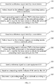
- the method is executed by user equipment UE, and as shown in FIG. 1 , the method includes:
- Step 101 Receive a reference signal sent by a base station.
- the reference signal sent by the base station may include a channel state information reference signal (channel state information Reference Signal, CSI RS), or a demodulation reference signal (demodulation RS, DM RS), or a cell-specific reference signal (cell-specific RS, CRS).
- the user equipment UE may obtain a resource configuration of the reference signal by receiving a notification of the eNB such as RRC (Radio Resource Control, Radio Resource Control) signaling or DCI (Downlink Control Information, downlink control information), or on the basis of a cell identity ID; and obtain the reference signal in a corresponding resource or subframe.
- RRC Radio Resource Control, Radio Resource Control
- DCI Downlink Control Information, downlink control information
- two column vectors (or referred to as beams) can be separately selected from each block matrix X i by using two e i , k in z i,k ; and phase alignment and weighting are performed on the two column vectors (or beams) by using ⁇ i,k and ⁇ i,k e j ⁇ i,k , where the two column vectors selected from X i may separately point to two major multipath transmission directions.
- the block diagonal matrix W 1 is a beam group formed by the block matrices X i that include different beams (or column vectors), and correspondingly, each column of each block matrix Z i included in the matrix Z is used to combine (including phase alignment and weighting) two beams in the block matrix X i , where directions of the two beams may separately point to two major multipath transmission directions. Therefore, for each column of an obtained matrix X i Z i , interference between two major multipath transmission directions can be converted into a wanted signal by using the foregoing structure, thereby significantly improving transmit power corresponding to each column of X i Z i .
- the parameters ⁇ i,k and ⁇ i,k may be equal, and in this case, equal-power combining gains of two beams are obtained.
- One of the parameters ⁇ i,k and ⁇ i,k may be 0, and in this case, selective combining gains of two beams are obtained.
- the parameters ⁇ i,k and ⁇ i,k may also be other quantized values, for example, a value of ⁇ i,k e j ⁇ i,k may be selected from a constellation diagram of modulation such as 16QAM or 64QAM, and in this case, maximum ratio combining gains of two beams are obtained.
- the matrix W 2 is used to select one or column vectors in the matrix W 1 Z and perform weighting combination to form the matrix w .
- the precoding matrix w can further adapt to a sub-band or a short-term characteristic of a channel, and one-layer or multi-layer transmission is formed, thereby improving a transmission rate.
- DFT Discrete Fourier Transform
- Each column of the matrix X i , j in formula (6) may also be selected from columns of a precoding matrix in an LTE R8 system 2-antenna or 4-antenna codebook or in an LTE RIO system 8-antenna codebook.
- each column of the matrix A i,j or the matrix B i,j in formula (11) may be a column vector of the Householder matrix shown in (7), or the DFT matrix shown in (8), or the Hadamard matrix or the rotated Hadamard matrix shown in (9) or (10), or the precoding matrix in the LTE R8 system 2-antenna or 4-antenna codebook or in the LTE R10 system 8-antenna codebook.
- other forms may also be used for the matrix A i,j or the matrix B i,j , which are not described in detail herein.
- the precoding matrix w can adapt to an antenna configuration of the AAS base station, thereby fully using freedom in horizontal and perpendicular directions of an antenna of the AAS base station.
- block matrices X i in formula (6) may be equal to each other, where 1 ⁇ i ⁇ N B ; in this way, relevance between channels can be fully used, and feedback overheads can be further reduced.
- the structure shown in (5) helps select two antenna ports by directly using two e i , k in z i,k , and helps perform phase alignment and weighting on the two antenna ports by using ⁇ i,k e j ⁇ i,k , where the two selected antenna ports may separately align with two major multipath transmission directions.
- An actually deployed antenna port may correspond to a virtual antenna, where each virtual antenna is obtained by performing weighting combination on multiple physical antennas, and virtual antennas may have different beam directions; therefore, in the foregoing precoding structure, different beam directions of the antenna ports can be fully used, and interference between two major multipath transmission directions can be directly converted into a wanted signal, thereby significantly improving a system transmission rate.
- the phase ⁇ i,k in the structure (5) may be selected from the following values: ⁇ i , k ⁇ 0 , 2 ⁇ N , ... , N ⁇ 1 2 ⁇ N where N is a positive integer, for example, N is 2 to the power of n, where n is a positive integer.
- the foregoing block matrices Z i may be equal to each other, where 1 ⁇ i ⁇ N B ; in this way, relevance between channels can be fully used, and feedback overheads can be further reduced.
- the matrix W 2 is used to select or perform weighting combination on a column vector in the matrix W 1 Z to form the matrix w .
- the selecting, based on the reference signal, a precoding matrix from a codebook may include: obtaining, by the user equipment UE based on the reference signal, channel estimation, and selecting the precoding matrix from the codebook according to the channel estimation and based on a predefined rule such as a rule of maximizing a channel capacity or a throughput, where selection, based on a predefined rule, of a precoding matrix is the prior art, and is not described in detail herein.
- a predefined rule such as a rule of maximizing a channel capacity or a throughput
- Step 103 Send a precoding matrix indicator PMI to the base station according to the selected precoding matrix w , where the PMI is used by the base station to obtain the selected precoding matrix W according to the PMI.
- the precoding matrix w is included in a precoding matrix set or a codebook, and the PMI is used to indicate the precoding matrix w selected from the precoding matrix set or the codebook.
- the sending a precoding matrix indicator PMI to the base station includes: sending the precoding matrix indicator PMI to the base station, where the PMI may only include a specific value, and in this case, the PMI directly indicates the precoding matrix w .
- the PMI may only include a specific value, and in this case, the PMI directly indicates the precoding matrix w .
- the PMI may only include a specific value, and in this case, the PMI directly indicates the precoding matrix w .
- the sending a precoding matrix indicator PMI to the base station may also include: sending precoding matrix indicators PMI 1 and PMI 2 to the base station, where the PMI 1 and the PMI 2 are respectively used to indicate the matrix W 1 Z and the matrix W 2 in formula (1), and in this case, the matrix W 1 Z and the matrix W 2 are respectively indicated by the PMI 1 and the PMI 2 in the codebook; or the sending a precoding matrix indicator PMI to the base station may also include: sending a third precoding matrix indicator PMI 3 and a fourth precoding matrix indicator PMI 4 to the base station, where the PMI 3 is used to indicate the matrix W 1 , and the PMI 4 is used to indicate the matrix ZW 2 ; or sending the second precoding matrix indicator PMI 2 , the third precoding matrix indicator PMI 3 , and a fifth precoding matrix indicator PMI 5 to the base station, where the PMI 5 is used to indicate Z
- the precoding matrix indicators PMI 1 and PMI 2 , or PMI 3 and PMI 4 , or PMI 2 , PMI 3 , and PMI 5 have different time domains or frequency domain granularities.
- the sending a precoding matrix indicator PMI to the base station specifically includes:
- the sizes of the foregoing wideband and sub-band may vary with the size of a system bandwidth.
- the wideband may include 50 RBs, and the size of the sub-band may be 6 consecutive RBs; and in a 5 MHz LTE system, the wideband may include 25 RBs, and the size of the sub-band may be 3 consecutive RBs.
- feedback overheads can be further reduced by using time or frequency domain relevance between channels.
- the sending a precoding matrix indicator PMI to the base station may also include: sending a precoding matrix indicator PMI1 i , where 1 ⁇ i ⁇ N B , and the PMI 2 to the base station; PMI i , where 1 ⁇ i ⁇ N B , and the PMI 2 are respectively used to indicate the matrix X i Z i , where 1 ⁇ i ⁇ N B , and the matrix W 2 ; or sending a precoding matrix indicator PMI3i, where 1 ⁇ i ⁇ N B , and the PMI 4 to the base station; PMI3i, where 1 ⁇ i ⁇ N B , is used to indicate X i and the PMI 4 is used to indicate the matrix ZW 2 ; or sending a precoding matrix indicator PMI3i, where 1 ⁇ i ⁇ N B , the PMI 2 , and the PMI 5 to the base station, where the PMI 5 is used to indicate Z .
- the sending a precoding matrix indicator PMI to the base station may be: sending, by the UE, the precoding matrix indicator PMI to the base station through a physical uplink control channel (Physical Uplink Control Channel, PUCCH) or a physical uplink shared channel (Physical Uplink Shared Channel, PUSCH).
- a physical uplink control channel Physical Uplink Control Channel, PUCCH
- a physical uplink shared channel Physical Uplink Shared Channel, PUSCH
- the sending a precoding matrix indicator PMI to the base station may be: separately sending, by the UE to the base station by using different subframes or in different periods, the PMI 1 and the PMI 2 , or the PMI 3 and the PMI 4 , or the PMI 2 , the PMI 3 , and the PMI 5 , or the PMI1 i , where 1 ⁇ i ⁇ N B , and the PMI 2 , or the PMI3,i and the PMI 4 , or the PMI3i, where 1 ⁇ i ⁇ N B , the PMI 2 , and the PMI 5 , or the PMI5i, where 1 ⁇ i ⁇ N B /2, and the PMI 2 .
- the sending a precoding matrix indicator PMI to the base station may also be: separately sending, by the UE to the base station according to different sub-bands or sub-band widths in a frequency domain, the PMI 1 and the PMI 2 , or the PMI 3 and the PMI 4 , or the PMI 2 , the PMI 3 , and the PMI 5 , or the PMI1 i , where 1 ⁇ i ⁇ N B , and the PMI 2 , or the PMI3,i and the PMI 4 , or the PMI3i, where 1 ⁇ i ⁇ N B , the PMI 2 , and the PMI 5 , or the PMI5i, where 1 ⁇ i ⁇ N B /2, and the PMI 2 .
- multiple block matrices X i may separately correspond to antenna groups of different polarizations or different locations; therefore, the precoding matrix can match multiple antenna deployments or configurations.
- the foregoing codebook structure can significantly improve performance of MIMO, especially MU-MIMO.
- one or more PMIs are fed back based on a subset, to indicate the precoding matrix; therefore, time/frequency domain/space relevance between channels is fully used, thereby significantly reducing feedback overheads.
- the selecting, based on the reference signal, a precoding matrix from a codebook is specifically: 202: Select, based on the reference signal, the precoding matrix from a codebook subset.
- the codebook subset may be a predefined codebook subset; or may be a codebook subset as follows: the codebook subset is reported by the UE to the base station eNB, determined by the base station eNB based on a report of the UE, and then told by the base station to the UE; or may be a codebook subset that is determined and reported by the UE, for example, a recently reported codebook subset.
- codebook subset and another codebook subset share at least one same matrix subset of the following matrix subsets: subsets of a matrix W 1 , a matrix W 1 Z , a matrix W 2 , a matrix ZW 2 , and a matrix Z .
- the precoding matrix is selected based on the codebook subset, which can further reduce feedback overheads and implementation complexity.
- the codebook subsets share a same subset of the matrix W 1 , or the matrix W 1 Z , or the matrix W 2 , or the matrix ZW 2 , or the matrix Z, and therefore, the codebook subsets overlap with each other, which can overcome an edge effect of quantization of channel state information.
- the block matrices X i of the block diagonal matrix W 1 may be unequal, or may be equal. If the block diagonal matrix W 1 has multiple equal block matrices, for example, equal block matrices may appear in pairs, feedback overheads can be further reduced.
- the three matrices W 1 , Z , and W 2 included in the precoding matrix w that is selected, based on the reference signal, from the codebook may further be multiplied by a scale factor, so as to implement power normalization or power balancing.
- the codebook may further include other precoding matrices, so as to meet requirements of other scenarios, which is not limited herein.
- This embodiment of the present invention provides the method for reporting channel state information.
- two column vectors (or referred to as beams) can be separately selected from each block matrix X i by using the structure of the matrix Z ; and phase alignment and weighting are performed on the two column vectors (or beams), where the two column vectors selected from X i may separately point to two major multipath transmission directions. Therefore, by using the foregoing structure, for each column of an obtained matrix X i Z i , interference between two major multipath transmission directions can be converted into a wanted signal, and combining gains are obtained, thereby improving system transmission reliability and a system transmission throughput.
- This embodiment of the present invention further provides a method for reporting channel state information.
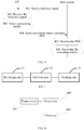
- the method is executed by a base station, and as shown in FIG. 3 , the method includes:
- the codebook may further include other precoding matrices, so as to meet requirements of other scenarios, which is not limited herein.
- two column vectors (or referred to as beams) can be separately selected from each block matrix X i by using the structure of the matrix Z ; and phase alignment and weighting are performed on the two column vectors (or beams), where the two column vectors selected from X i may separately point to two major multipath transmission directions. Therefore, by using the foregoing structure, for each column of an obtained matrix X i Z i , interference between two major multipath transmission directions can be converted into a wanted signal, and combining gains are obtained, thereby improving system transmission reliability and a system transmission throughput.
- the following describes in detail interaction between devices for implementing a method for reporting channel state information provided in this embodiment of the present invention, and as shown in FIG. 4 , the method includes:
- two column vectors (or referred to as beams) can be separately selected from each block matrix X i by using the foregoing structure; and phase alignment and weighting are performed on the two column vectors (or beams), where the two column vectors selected from X i may separately point to two major multipath transmission directions. Therefore, by using the foregoing structure, for each column of an obtained matrix X i Z i , interference between two major multipath transmission directions can be converted into a wanted signal, and combining gains are obtained, thereby improving system transmission reliability and a system transmission throughput.
- the user equipment includes: a receiving unit 51, a selection unit 52, and a sending unit 53.
- the receiving unit 51 is configured to receive a reference signal sent by a base station.
- the sending unit 53 is configured to send a precoding matrix indicator PMI to the base station, where the PMI corresponds to the selected precoding matrix, and is used by the base station to obtain the selected precoding matrix w according to the PMI.
- the selection unit 52 is specifically configured to select, based on the reference signal, the precoding matrix from a codebook subset, where the codebook subset is a subset predefined, or notified by the base station, or determined by the user equipment.
- the codebook subsets share at least one same matrix subset of the following matrix subsets: subsets of a matrix W 1 , a matrix W 1 Z, a matrix W 2 , a matrix ZW 2 , and a matrix Z .
- the sending unit 53 may be specifically configured to send a first precoding matrix indicator PMI 1 and a second precoding matrix indicator PMI 2 to the base station, where the PMI 1 is used to indicate the matrix W 1 Z , and the PMI 2 is used to indicate the matrix W 2 ; or send a third precoding matrix indicator PMI 3 and a fourth precoding matrix indicator PMI 4 to the base station, where the PMI 3 is used to indicate the matrix W 1 , and the PMI 4 is used to indicate the matrix ZW 2 ; or send the second precoding matrix indicator PMI 2 , the third precoding matrix indicator PMI 3 , and a fifth precoding matrix indicator PMI 5 to the base station, where the PMI 5 is used to indicate Z
- the sending unit 53 may be specifically configured to send the PMI 1 to the base station according to a first period; and send the PMI 2 to the base station according to a second period, where the first period is greater than the second period; or send the PMI 3 to the base station according to a third period; and send the PMI 4 to the base station according to a fourth period, where the third period is greater than the fourth period; or send the PMI 2 to the base station according to a second period; send the PMI 3 to the base station according to a third period; and send the PMI 5 to the base station according to a fifth period, where the third period is less than the second period and the fifth period.
- the sending unit 53 may further be specifically configured to send the PMI 1 to the base station according to a first frequency domain granularity; and send the PMI 2 to the base station according to a second frequency domain granularity, where the first frequency domain granularity is greater than the second frequency domain granularity, for example, send a wideband PMI 1 and a sub-band PMI 2 to the base station; or send the PMI 3 to the base station according to a third frequency domain granularity; and send the PMI 4 to the base station according to a fourth frequency domain granularity, where the third frequency domain granularity is greater than the fourth frequency domain granularity, for example, send a wideband PMI 3 and a sub-band PMI 4 to the base station; or send the PMI 2 to the base station according to a second frequency domain granularity; send the PMI 3 to the base station according to a third frequency domain granularity; and send the PMI 5 to the base station according to a fifth frequency domain granularity,
- the sizes of the foregoing wideband and sub-band may vary with the size of a system bandwidth.
- the wideband may include 50 physical resource blocks RBs, and the size of the sub-band may be 6 consecutive RBs; and in a 5 MHz LTE system, the wideband may include 25 RBs, and the size of the sub-band may be 3 consecutive RBs.
- the block matrix X i [ X i ,1 X i ,2 ], where each column of the matrix X i,j is selected from columns of a Householder matrix, a discrete Fourier transform matrix, a Hadamard matrix, a rotated Hadamard matrix, or a precoding matrix in an LTE R8 system 2-antenna or 4-antenna codebook or in an LTE RIO system 8-antenna codebook.
- columns of the matrix X i ,1 and the matrix X i, 2 are column vectors of a Householder matrix, a discrete Fourier transform matrix, a Hadamard matrix, a rotated Hadamard matrix, or a precoding matrix in an LTE R8 system 2-antenna or 4-antenna codebook or in an LTE R10 system 8-antenna codebook.
- W 1 is an identity matrix.
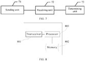
- the user equipment includes: a transceiver 601, a memory 602, and a processor 603.
- the user equipment may further include common-purpose components such as an antenna and an input output apparatus, which is not limited herein in this embodiment of the present invention.
- the memory 602 stores a set of program code
- the selecting, based on the reference signal, a precoding matrix from a codebook specifically includes: selecting, based on the reference signal, the precoding matrix from a codebook subset, where the codebook subset is a subset predefined, or notified by the base station, or reported by the user equipment.
- the codebook subsets share at least one same matrix subset of the following matrix subsets: subsets of a matrix W 1 , a matrix W 1 Z , a matrix W 2 , a matrix ZW 2 , and a matrix Z .
- the sending a precoding matrix indicator PMI to the base station by using the transceiver 61 specifically includes:
- the sending a precoding matrix indicator PMI to the base station by using the transceiver 61 specifically includes:
- the sending a precoding matrix indicator PMI to the base station by using the transceiver 61 specifically includes:
- the sizes of the foregoing wideband and sub-band may vary with the size of a system bandwidth.
- the wideband may include 50 physical resource blocks RBs, and the size of the sub-band may be 6 consecutive RBs; and in a 5 MHz LTE system, the wideband may include 25 RBs, and the size of the sub-band may be 3 consecutive RBs.
- the block matrix X i [ X i ,1 X i ,2 ], where each column of the matrix X i , j is selected from columns of a Householder matrix, a discrete Fourier transform matrix, a Hadamard matrix, a rotated Hadamard matrix, or a precoding matrix in an LTE R8 system 2-antenna or 4-antenna codebook or in an LTE RIO system 8-antenna codebook.
- columns of the matrix X i ,1 and the matrix X i ,2 are column vectors of a Householder matrix, a discrete Fourier transform matrix, a Hadamard matrix, a rotated Hadamard matrix, or a precoding matrix in an LTE R8 system 2-antenna or 4-antenna codebook or in an LTE R10 system 8-antenna codebook.
- W 1 is an identity matrix.
- the codebook may further include other precoding matrices, so as to meet requirements of other scenarios, which is not limited herein.
- two column vectors (or referred to as beams) can be separately selected from each block matrix X i by using the foregoing structure; and phase alignment and weighting are performed on the two column vectors (or beams), where the two column vectors selected from X i may separately point to two major multipath transmission directions. Therefore, by using the foregoing structure, for each column of an obtained matrix X i Z i , interference between two major multipath transmission directions can be converted into a wanted signal, and combining gains are obtained, thereby improving system transmission reliability and a system transmission throughput.
- the base station includes: a sending unit 71, a receiving unit 72, and a determining unit 73.
- the sending unit 71 is configured to send a reference signal to user equipment UE.
- the receiving unit 72 is configured to receive a precoding matrix indicator PMI sent by the UE.
- the determining unit 73 is specifically configured to determine the precoding matrix in a codebook subset according to the PMI, where the codebook subset is a subset predefined, or reported by the user equipment, or determined by the base station.
- the codebook subsets share at least one same matrix subset of the following matrix subsets: subsets of a matrix W 1 , a matrix W 1 Z , a matrix W 2 , a matrix ZW 2 , and a matrix Z.
- the receiving unit 72 is specifically configured to:
- the receiving unit 72 is specifically configured to:
- the receiving unit 72 is specifically configured to:
- the sizes of the foregoing wideband and sub-band may vary with the size of a system bandwidth.
- the wideband may include 50 physical resource blocks RBs, and the size of the sub-band may be 6 consecutive RBs; and in a 5 MHz LTE system, the wideband may include 25 RBs, and the size of the sub-band may be 3 consecutive RBs.
- the block matrix X i [ X i ,1 X i ,2 ], where each column of the matrix X i , j is selected from columns of a Householder matrix, a discrete Fourier transform matrix, a Hadamard matrix, a rotated Hadamard matrix, or a precoding matrix in an LTE R8 system 2-antenna or 4-antenna codebook or in an LTE RIO system 8-antenna codebook.
- each column of the matrix X i , j is separately selected from columns of different Householder matrices, different discrete Fourier transform matrices, different Hadamard matrices, different rotated Hadamard matrices, or different precoding matrices in an LTE R8 system 2-antenna or 4-antenna codebook or in an LTE R10 system 8-antenna codebook.
- columns of the matrix X i ,1 and the matrix X i ,2 are column vectors of a Householder matrix, a discrete Fourier transform matrix, a Hadamard matrix, a rotated Hadamard matrix, or a precoding matrix in an LTE R8 system 2-antenna or 4-antenna codebook or in an LTE R10 system 8-antenna codebook.
- W 1 is an identity matrix.
- the base station includes: a transceiver 801, a memory 802, and a processor 803.
- the base station may further include common-purpose components such as an antenna and an input/output apparatus, which is not limited herein in this embodiment of the present invention.
- the memory 802 stores a set of program code
- the determining a precoding matrix w in a codebook according to the PMI specifically includes: determining the precoding matrix in a codebook subset according to the PMI, where the codebook subset is a subset predefined, or reported by the user equipment, or determined by the base station.
- the codebook subsets share at least one same matrix subset of the following matrix subsets: subsets of a matrix W 1 , a matrix W 1 Z , a matrix W 2 , a matrix ZW 2 , and a matrix Z.
- the receiving the PMI by using the transceiver 81 may specifically include: receiving a first precoding matrix indicator PMI 1 and a second precoding matrix indicator PMI 2 that are sent by the UE, where the PMI 1 is used to indicate the matrix W 1 Z , and the PMI 2 is used to indicate the matrix W 2 ; or receiving a third precoding matrix indicator PMI 3 and a fourth precoding matrix indicator PMI 4 that are sent by the UE, where the PMI 3 is used to indicate the matrix W 1 , and the PMI 4 is used to indicate the matrix ZW 2 ; or receiving the second precoding matrix indicator PMI 2 , the third precoding matrix indicator PMI 3 , and a fifth precoding matrix indicator PMI 5 that are sent by the UE, where the PMI 5 is used to indicate Z.
- the receiving the PMI by using the transceiver 81 may specifically include: receiving, according to a first period, the PMI 1 sent by the UE; and receiving, according to a second period, the PMI 2 sent by the UE, where the first period is greater than the second period; or receiving, according to a third period, the PMI 3 sent by the UE; and receiving, according to a fourth period, the PMI 4 sent by the UE, where the third period is greater than the fourth period; or receiving, according to a second period, the PMI 2 sent by the UE; receiving, according to a third period, the PMI 3 sent by the UE; and receiving, according to a fifth period, the PMI 5 sent by the UE, where the third period is less than the second period and the fifth period.
- the receiving the PMI by using the transceiver 81 may further specifically include: receiving, according to a first frequency domain granularity, the PMI 1 sent by the UE; and receiving, according to a second frequency domain granularity, the PMI 2 sent by the UE, where the first frequency domain granularity is greater than the second frequency domain granularity, for example, receiving a wideband PMI 1 and a sub-band PMI 2 that are sent by the UE; or receiving, according to a third frequency domain granularity, the PMI 3 sent by the UE; and receiving, according to a fourth frequency domain granularity, the PMI 4 sent by the UE, where the third frequency domain granularity is greater than the fourth frequency domain granularity, for example, receiving a wideband PMI 3 and a sub-band PMI 4 that are sent by the UE; or receiving, according to a second frequency domain granularity, the PMI 2 sent by the UE; receiving, according to a third frequency domain granularity
- the sizes of the foregoing wideband and sub-band may vary with the size of a system bandwidth.
- the wideband may include 50 physical resource blocks RBs, and the size of the sub-band may be 6 consecutive RBs; and in a 5 MHz LTE system, the wideband may include 25 RBs, and the size of the sub-band may be 3 consecutive RBs.
- the block matrix X i [ X i ,1 X i ,2 ], where each column of the matrix X i,j is selected from columns of a Householder matrix, a discrete Fourier transform matrix, a Hadamard matrix, a rotated Hadamard matrix, or a precoding matrix in an LTE R8 system 2-antenna or 4-antenna codebook or in an LTE RIO system 8-antenna codebook.
- each column of the matrix X i,j is separately selected from columns of different Householder matrices, different discrete Fourier transform matrices, different Hadamard matrices, different rotated Hadamard matrices, or different precoding matrices in an LTE R8 system 2-antenna or 4-antenna codebook or in an LTE RIO system 8-antenna codebook.
- columns of the matrix X i ,1 and the matrix X i ,2 are column vectors of a Householder matrix, a discrete Fourier transform matrix, a Hadamard matrix, a rotated Hadamard matrix, or a precoding matrix in an LTE R8 system 2-antenna or 4-antenna codebook or in an LTE RIO system 8-antenna codebook.
- W 1 is an identity matrix.
- the codebook may further include other precoding matrices, so as to meet requirements of other scenarios, which is not limited herein.
- two column vectors (or referred to as beams) can be separately selected from each block matrix X i by using the foregoing structure; and phase alignment and weighting are performed on the two column vectors (or beams), where the two column vectors selected from X i may separately point to two major multipath transmission directions. Therefore, by using the foregoing structure, for each column of an obtained matrix X i Z i , interference between two major multipath transmission directions can be converted into a wanted signal, and combining gains are obtained, thereby improving system transmission reliability and a system transmission throughput.
- the disclosed system, apparatus, and method may be implemented in other manners.
- the described apparatus embodiment is merely exemplary.
- the module or unit division is merely logical function division and may be other division in actual implementation.
- a plurality of units or components may be combined or integrated into another system, or some features may be ignored or not performed.
- the displayed or discussed mutual couplings or direct couplings or communication connections may be implemented through some interfaces.
- the indirect couplings or communication connections between the apparatuses or units may be implemented in electronic, mechanical, or other forms.
- the units described as separate parts may or may not be physically separate, and parts displayed as units may or may not be physical units, may be located in one position, or may be distributed on a plurality of network units. Some or all of the units may be selected according to actual needs to achieve the objectives of the solutions of the embodiments.
- functional units in the embodiments of the present invention may be integrated into one processing unit, or each of the units may exist alone physically, or two or more units are integrated into one unit.
- the integrated unit may be implemented in a form of hardware, or may be implemented in a form of a software functional unit.
- the integrated unit When the integrated unit is implemented in the form of a software functional unit and sold or used as an independent product, the integrated unit may be stored in a computer-readable storage medium. Based on such an understanding, the technical solutions of the present invention essentially, or the part contributing to the prior art, or all or some of the technical solutions may be implemented in the form of a software product.
- the software product is stored in a storage medium and includes several instructions for instructing a computer device (which may be a personal computer, a server, or a network device) or a processor to perform all or some of the steps of the methods described in the embodiments of the present invention.
- the foregoing storage medium includes: any medium that can store program code, such as a USB flash drive, a removable hard disk, a read-only memory (ROM, Read-Only Memory), a random access memory (RAM, Random Access Memory), a magnetic disk, or an optical disc.
- program code such as a USB flash drive, a removable hard disk, a read-only memory (ROM, Read-Only Memory), a random access memory (RAM, Random Access Memory), a magnetic disk, or an optical disc.
Landscapes
- Engineering & Computer Science (AREA)
- Computer Networks & Wireless Communication (AREA)
- Signal Processing (AREA)
- Physics & Mathematics (AREA)
- Mathematical Physics (AREA)
- Mobile Radio Communication Systems (AREA)
- Radio Transmission System (AREA)
Abstract
Description
- The present invention relates to the field of communications technologies, and in particular, to a method for reporting channel state information, user equipment, and a base station.
- In a multiple input multiple output (Multiple Input Multiple Output, MIMO for short) system, to eliminate co-channel interference caused by multiple users and multiple antennas, some necessary signal processing technologies need to be used at two ends of a transceiver, so as to improve communication performance of the system.
- In the prior art, a precoding technology is proposed, and a major principle of the precoding technology is that a base station uses known channel state information (Channel State Information, CSI for short) to design a precoding matrix for processing a sent signal, so as to reduce interference on the sent signal. A MIMO system using precoding may be represented as follows:

- Optimal precoding usually requires that a transmitter entirely knows channel state information (Channel State Information, CSI for short). In a common method, a terminal quantizes instantaneous CSI and feeds back the instantaneous CSI to a base station (Base station, BS for short).
- In an existing long term evolution (Long Term Evolution, LTE for short) R8 system, CSI information fed back by a terminal includes information such as a rank indicator (Rank Indicator, RI for short), a precoding matrix indicator (Precoding Matrix Indicator, PMI for short), and a channel quality indicator (Channel Quality Indicator, CQI for short), where the RI and the PMI respectively indicate a used layer quantity and a used precoding matrix. A set of used precoding matrices is generally referred to as a codebook, where each precoding matrix is a code word in the codebook. An existing LTE R8 4-antenna codebook is designed based on a Householder Householder transformation, and a code word of the codebook may be compatible with a uniform linear array antenna configuration and a cross polarization antenna configuration. Double-codebook design for 8 antennas is introduced in an LTE RIO system, and quantization accuracy is further improved without excessively increasing feedback overheads.
- On one hand, the foregoing LTE R8 to R10 codebooks are mainly designed for a macro cell system. A position of a base station or a transmitter is usually higher than the height of a surrounding building (for example, the height of an antenna is approximately between 200 to 250 feet); therefore, a major transmission path of the base station or the transmitter is higher than a roof, and a transmitted multipath component usually surrounds a direction of a line of sight (Line of Sight, LOS for short). In this way, each multipath component is usually located within a plane in which the line of sight is located, that is, angle extension in a pitch angle direction approaches 0. On the other hand, the foregoing codebooks are designed based on a conventional base station antenna; for the conventional base station antenna, a perpendicular antenna beam having a fixed tilt angle is used, but only a direction of a horizontal beam can be adjusted dynamically.
- However, to conform to user density and a data service demand that are increasing rapidly, and to further reduce transmit power, the concept of micro cell is further introduced. A position of a base station or a transmitter in a micro cell system is usually lower than the height of a surrounding building (for example, an antenna is installed on a lamppost in a street, and usually is at a height of approximately 30 feet), and a wireless transmission mechanism of the micro cell system is obviously different from the foregoing macro cell environment, where some multipath components may surround a LOS direction, and some other multipath components are probably along the ground or the street. This double-transmission mechanism causes larger angle extension, especially in a direction of a pitch angle, which is obviously different from the macro cell. Currently, design of LTE R8-R10 codebooks cannot be well adapted to the foregoing micro cell environment.
- In addition, to further improve spectrum efficiency, currently, in an LTE R12 standard to be launched, introduction of more antenna configurations, especially an antenna configuration based on an active antenna system (Active antenna system, AAS for short), starts to be considered. Different from a conventional base station, an AAS base station further provides freedom in designing an antenna in a perpendicular direction, which is mainly implemented by using a two-dimensional antenna array in horizontal and perpendicular directions of the antenna; the conventional base station actually uses a horizontal one-dimensional array, although each antenna port in a horizontal direction of the antenna may be obtained by performing weighting on multiple array elements in a perpendicular direction. Currently, the design of the LTE R8-R10 codebooks cannot be well adapted to the foregoing antenna configuration.
- Embodiments of the present invention provide a method for reporting channel state information, user equipment, and a base station. In a precoding matrix indicated in the channel state information reported by the user equipment, a channel characteristic of a double-transmission condition in a micro cell network environment and freedom in horizontal and perpendicular directions of an antenna of an AAS base station are considered, which can improve communication performance of the micro cell network environment and an AAS base station system.
- To achieve the foregoing objective, the following technical solutions are used in the embodiments of the present invention:
- According to a first aspect, an embodiment of the present invention provides a method for reporting channel state information, where the method includes:
- receiving a reference signal sent by a base station;
- selecting, based on the reference signal, a precoding matrix from a codebook, where a precoding matrix w included in the codebook is a product of three matrices being W 1, Z, and W 2, that is, W = W 1 ZW 2, where
- both W 1 and Z are block diagonal matrices, W 1=diag{X 1,...,X N
B }, Z=diag{Z 1,...,Z NB }, each of W 1 and Z includes at least one block matrix, that is, NB ≥ 1, and each column of each block matrix Z i in the matrix Z has the following structure:
- where [ ] T represents matrix transposition; e i,k represents an n i x1 selection vector, where in the vector, the kth element is 1 and all other elements are 0, and n i is a half of a column quantity of a block matrix X i ; θi,k is a phase shift, αi,k ≥ 0, and βi,k ≥ 0; and
- sending a precoding matrix indicator PMI to the base station, where the PMI is used by the base station to obtain the selected precoding matrix w according to the PMI.
- In a first possible implementation manner, with reference to the first aspect, the selecting, based on the reference signal, a precoding matrix from a codebook specifically includes:
selecting, based on the reference signal, the precoding matrix from a codebook subset, where the codebook subset is a subset predefined, or notified by the base station, or determined by user equipment. - In a second possible implementation manner, with reference to the first possible implementation manner, the codebook subsets share at least one same matrix subset of the following matrix subsets: subsets of a matrix W 1, a matrix W1Z, a matrix W 2, a matrix ZW2 , and a matrix Z .
- In a third possible implementation manner, with reference to the first aspect or the first and second possible implementation manners, the sending a precoding matrix indicator PMI to the base station specifically includes:
- sending a first precoding matrix indicator PMI1 and a second precoding matrix indicator PMI2 to the base station, where the PMI1 is used to indicate the matrix W1Z, and the PMI2 is used to indicate the matrix W2 ; or
- sending a third precoding matrix indicator PMI3 and a fourth precoding matrix indicator PMI4 to the base station, where the PMI3 is used to indicate the matrix W 1, and the PMI4 is used to indicate the matrix ZW2 ; or
- sending the second precoding matrix indicator PMI2, the third precoding matrix indicator PMI3, and a fifth precoding matrix indicator PMI5 to the base station, where the PMI5 is used to indicate Z
- In a fourth possible implementation manner, with reference to the third possible implementation manner, the sending a precoding matrix indicator PMI to the base station specifically includes:
- sending the PMI1 to the base station according to a first period; and
- sending the PMI2 to the base station according to a second period, where the first period is greater than the second period; or
- sending the PMI3 to the base station according to a third period; and
- sending the PMI4 to the base station according to a fourth period, where the third period is greater than the fourth period; or
- sending the PMI2 to the base station according to a second period;
- sending the PMI3 to the base station according to a third period; and
- sending the PMI5 to the base station according to a fifth period, where the third period is less than the second period and the fifth period.
- In a fifth possible implementation manner, with reference to the third possible implementation manner, the sending a precoding matrix indicator PMI to the base station specifically includes:
- sending the PMI1 to the base station according to a first frequency domain granularity; and
- sending the PMI2 to the base station according to a second frequency domain granularity, where the first frequency domain granularity is greater than the second frequency domain granularity; or
- sending the PMI3 to the base station according to a third frequency domain granularity; and
- sending the PMI4 to the base station according to a fourth frequency domain granularity, where the third frequency domain granularity is greater than the fourth frequency domain granularity; or
- sending the PMI2 to the base station according to a second frequency domain granularity;
- sending the PMI3 to the base station according to a third frequency domain granularity; and
- sending the PMI5 to the base station according to a fifth frequency domain granularity, where the third frequency domain granularity is less than the second frequency domain granularity and the fifth frequency domain granularity.
- In a sixth possible implementation manner, with reference to the first aspect or the first to fifth possible implementation manners, the block matrix X i = [X i,1 X i,2], where each column of the matrix X i,j is selected from columns of a Householder matrix, a discrete Fourier transform matrix, a Hadamard matrix, a rotated Hadamard matrix, or a precoding matrix in an LTE R8 system 2-antenna or 4-antenna codebook or in an LTE RIO system 8-antenna codebook.
- In a seventh possible implementation manner, with reference to the sixth possible implementation manner, each column of the matrix X i,j , j = 1, 2 is separately selected from columns of different Householder matrices, different discrete Fourier transform matrices, different Hadamard matrices, different rotated Hadamard matrices, or different precoding matrices in an LTE R8 system 2-antenna or 4-antenna codebook or in an LTE RIO system 8-antenna codebook.
- In an eighth possible implementation manner, with reference to the first aspect or the first to fifth possible implementation manners, the block matrix X i = [X i,1 X i,2], where the matrix X i,j is a Kronecker product of two matrices being A i,j and B i,j , and j = 1, 2.
- In a ninth possible implementation manner, with reference to the eighth possible implementation manner, columns of the matrix X i,1 and the matrix X i,2 are column vectors of a Householder matrix, a DFT matrix, a Hadamard matrix, a rotated Hadamard matrix, or a precoding matrix in an LTE R8 system 2-antenna or 4-antenna codebook or in an LTE R10 system 8-antenna codebook.
- In a tenth possible implementation manner, with reference to the first aspect or the first to ninth possible implementation manners, W 1 is an identity matrix.
- In an eleventh possible implementation manner, with reference to the first aspect or the first to tenth possible implementation manners, a column vector in the matrix W 2 has a structure

- According to a second aspect, an embodiment of the present invention provides a method for reporting channel state information, where the method includes:
- sending a reference signal to user equipment UE;
- receiving a precoding matrix indicator PMI sent by the UE; and
- determining a precoding matrix w in a codebook according to the PMI, where the precoding matrix W is a product of three matrices being W 1, Z, and W 2, that is, W = W 1 ZW 2, where
- both W 1 and Z are block diagonal matrices, W 1 = diag{X 1,...,X N
B }, Z = diag{Z 1,...,Z NB }, each of W 1 and Z includes at least one block matrix, that is, NB ≥ 1, and each column of each block matrix Z i in the matrix Z has the following structure:
- In a first possible implementation manner, with reference to the second aspect, the determining a precoding matrix w in a codebook according to the PMI specifically includes:
determining the precoding matrix in a codebook subset according to the PMI, where the codebook subset is a subset predefined, or reported by the user equipment, or determined by a base station. - In a second possible implementation manner, with reference to the first possible implementation manner, the codebook subsets share at least one same matrix subset of the following matrix subsets: subsets of a matrix W 1, a matrix W 1 Z, a matrix W 2, a matrix ZW 2, and a matrix Z .
- In a third possible implementation manner, with reference to the second aspect or the first and second possible implementation manners, the receiving a precoding matrix indicator PMI sent by the UE specifically includes:
- receiving a first precoding matrix indicator PMI1 and a second precoding matrix indicator PMI2 that are sent by the UE, where the PMI1 is used to indicate the matrix W 1 Z, and the PMI2 is used to indicate the matrix W 2;
- or
- receiving a third precoding matrix indicator PMI3 and a fourth precoding matrix indicator PMI4 that are sent by the UE, where the PMI3 is used to indicate the matrix W 1, and the PMI4 is used to indicate the matrix ZW2 ;
- or
- receiving the second precoding matrix indicator PMI2, the third precoding matrix indicator PMI3, and a fifth precoding matrix indicator PMI5 that are sent by the UE, where the PMI5 is used to indicate Z
- In a fourth possible implementation manner, with reference to the third possible implementation manner, the receiving a precoding matrix indicator PMI sent by the UE specifically includes:
- receiving, according to a first period, the PMI1 sent by the UE; and
- receiving, according to a second period, the PMI2 sent by the UE, where the first period is greater than the second period; or
- receiving, according to a third period, the PMI3 sent by the UE; and
- receiving, according to a fourth period, the PMI4 sent by the UE, where the third period is greater than the fourth period; or
- receiving, according to a second period, the PMI2 sent by the UE;
- receiving, according to a third period, the PMI3 sent by the UE; and
- receiving, according to a fifth period, the PMI5 sent by the UE, where the third period is less than the second period and the fifth period.
- In a fifth possible implementation manner, with reference to the third possible implementation manner, the receiving a precoding matrix indicator PMI sent by the UE specifically includes:
- receiving, according to a first frequency domain granularity, the PMI1 sent by the UE; and
- receiving, according to a second frequency domain granularity, the PMI2 sent by the UE, where the first frequency domain granularity is greater than the second frequency domain granularity; or
- receiving, according to a third frequency domain granularity, the PMI3 sent by the UE; and
- receiving, according to a fourth frequency domain granularity, the PMI4 sent by the UE, where the third frequency domain granularity is greater than the fourth frequency domain granularity; or
- receiving, according to a second frequency domain granularity, the PMI2 sent by the UE;
- receiving, according to a third frequency domain granularity, the PMI3 sent by the UE; and
- receiving, according to a fifth frequency domain granularity, the PMI5 sent by the UE, where the third frequency domain granularity is less than the second frequency domain granularity and the fifth frequency domain granularity.
- In a sixth possible implementation manner, with reference to the second aspect or the first to fifth possible implementation manners, the block matrix X i = [X i,1 X i,2], where each column of the matrix X i,j is selected from columns of a Householder matrix, a discrete Fourier transform matrix, a Hadamard matrix, a rotated Hadamard matrix, or a precoding matrix in an LTE R8 system 2-antenna or 4-antenna codebook or in an LTE RIO system 8-antenna codebook.
- In a seventh possible implementation manner, with reference to the sixth possible implementation manner, each column of the matrix X i,j , j = 1, 2 is separately selected from columns of different Householder matrices, different discrete Fourier transform matrices, different Hadamard matrices, different rotated Hadamard matrices, or different precoding matrices in an LTE R8 system 2-antenna or 4-antenna codebook or in an LTE R10 system 8-antenna codebook.
- In an eighth possible implementation manner, with reference to the first aspect or the first to fifth possible implementation manners, the block matrix X i = [X i,1 X i,2], where the matrix X i,j is a Kronecker product of a matrix A i,j and a matrix B i,j , and j = 1,2.
- In a ninth possible implementation manner, with reference to the eighth possible implementation manner, columns of the matrix X i,1 and the matrix X i,2 are column vectors of a Householder matrix, a discrete Fourier transform matrix, a Hadamard matrix, a rotated Hadamard matrix, or a precoding matrix in an LTE R8 system 2-antenna or 4-antenna codebook or in an LTE R10 system 8-antenna codebook.
- In a tenth possible implementation manner, with reference to the second aspect or the first to ninth possible implementation manners, W 1 is an identity matrix.
- In an eleventh possible implementation manner, with reference to the second aspect or the first to tenth possible implementation manners, a column vector in the matrix W 2 has a structure

- According to a third aspect, an embodiment of the present invention provides user equipment, where the user equipment includes: a receiving unit, a selection unit, and a sending unit, where
the receiving unit is configured to receive a reference signal sent by a base station;
the selection unit is configured to select, based on the reference signal, a precoding matrix from a codebook, where a precoding matrix w included in the codebook is a product of three matrices being W 1, Z, and W 2, that is, W = W 1 ZW 2, where
both W 1 and Z are block diagonal matrices, W 1=diag{X 1,...,X NB }, Z=diag{Z 1,...,Z NB }, each of W 1 and Z includes at least one block matrix, that is, NB ≥ 1, and each column of each block matrix Z i in the matrix Z has the following structure:
- where [ ] T represents matrix transposition; e i,k represents an n i x1 selection vector, where in the vector, the kth element is 1 and all other elements are 0, and n i is a half of a column quantity of a block matrix X i ; θ i,k is a phase shift, αi,k ≥ 0, and βi,k ≥ 0; and
- the sending unit is configured to send a precoding matrix indicator PMI to the base station, where the PMI corresponds to the selected precoding matrix, and is used by the base station to obtain the selected precoding matrix w according to the PMI.
- In a first possible implementation manner, with reference to the third aspect, the selection unit is specifically configured to select, based on the reference signal, the precoding matrix from a codebook subset, where the codebook subset is a subset predefined, or notified by the base station, or reported by the user equipment.
- In a second possible implementation manner, with reference to the first possible implementation manner, the codebook subsets share at least one same matrix subset of the following matrix subsets: subsets of a matrix W 1, a matrix W1Z, a matrix W 2, a matrix ZW2 , and a matrix Z .
- In a third possible implementation manner, with reference to the third aspect or the first and second possible implementation manners, the sending unit is specifically configured to send a first precoding matrix indicator PMI1 and a second precoding matrix indicator PMI2 to the base station, where the PMI1 is used to indicate the matrix W 1 Z, and the PMI2 is used to indicate the matrix W 2; or
send a third precoding matrix indicator PMI3 and a fourth precoding matrix indicator PMI4 to the base station, where the PMI3 is used to indicate the matrix W 1, and the PMI4 is used to indicate the matrix ZW 2; or
send the second precoding matrix indicator PMI2, the third precoding matrix indicator PMI3, and a fifth precoding matrix indicator PMI5 to the base station, where the PMI5 is used to indicate Z - In a fourth possible implementation manner, with reference to the third possible implementation manner, the sending unit is specifically configured to send the PMI1 to the base station according to a first period; and
send the PMI2 to the base station according to a second period, where the first period is greater than the second period; or
send the PMI3 to the base station according to a third period; and
send the PMI4 to the base station according to a fourth period, where the third period is greater than the fourth period; or
send the PMI2 to the base station according to a second period;
send the PMI3 to the base station according to a third period; and
send the PMI5 to the base station according to a fifth period, where the third period is less than the second period and the fifth period. - In a fifth possible implementation manner, with reference to the third possible implementation manner, the sending unit is specifically configured to send the PMI1 to the base station according to a first frequency domain granularity; and
send the PMI2 to the base station according to a second frequency domain granularity, where the first frequency domain granularity is greater than the second frequency domain granularity; or
send the PMI3 to the base station according to a third frequency domain granularity; and
send the PMI4 to the base station according to a fourth frequency domain granularity, where the third frequency domain granularity is greater than the fourth frequency domain granularity; or
send the PMI2 to the base station according to a second frequency domain granularity;
send the PMI3 to the base station according to a third frequency domain granularity; and
send the PMI5 to the base station according to a fifth frequency domain granularity, where the third frequency domain granularity is less than the second frequency domain granularity and the fifth frequency domain granularity. - In a sixth possible implementation manner, with reference to the third aspect or the first to fifth possible implementation manners, the block matrix X i =[X i,1 X i,2], where each column of the matrix X i,j is selected from columns of a Householder matrix, a discrete Fourier transform matrix, a Hadamard matrix, a rotated Hadamard matrix, or a precoding matrix in an LTE R8 system 2-antenna or 4-antenna codebook or in an LTE RIO system 8-antenna codebook.
- In a seventh possible implementation manner, with reference to the sixth possible implementation manner, each column of the matrix X i,j , j = 1, 2 is separately selected from columns of different Householder matrices, different discrete Fourier transform matrices, different Hadamard matrices, different rotated Hadamard matrices, or different precoding matrices in an LTE R8 system 2-antenna or 4-antenna codebook or in an LTE RIO system 8-antenna codebook.
- In an eighth possible implementation manner, with reference to the third aspect or the first to fifth possible implementation manners, the block matrix X i = [X i,1 X i,2], where the matrix X i,j is a Kronecker product of two matrices being A i,j and B i,j , and j = 1,2.
- In a ninth possible implementation manner, with reference to the eighth possible implementation manner, columns of the matrix X i,1 and the matrix X i,2 are column vectors of a Householder matrix, a discrete Fourier transform matrix, a Hadamard matrix, a rotated Hadamard matrix, or a precoding matrix in an LTE R8 system 2-antenna or 4-antenna codebook or in an LTE R10 system 8-antenna codebook.
- In a tenth possible implementation manner, with reference to the third aspect or the first to ninth possible implementation manners, W 1 is an identity matrix.
- In an eleventh possible implementation manner, with reference to the third aspect or the first to tenth possible implementation manners, a column vector in the matrix W 2 has a structure

- According to a fourth aspect, an embodiment of the present invention provides a base station, where the base station includes: a sending unit, a receiving unit, and a determining unit, where
the sending unit is configured to send a reference signal to user equipment UE;
the receiving unit is configured to receive a precoding matrix indicator PMI sent by the UE; and
the determining unit is configured to determine a precoding matrix w in a codebook according to the PMI, where the precoding matrix w is a product of three matrices being W 1, Z, and W 2, that is, W = W 1 ZW 2, where
both W 1 and Z are block diagonal matrices, W 1=diag{X 1,...,X NB }, Z=diag{Z 1,...,Z NB }, each of W 1 and Z includes at least one block matrix, that is, NB ≥ 1, and each column of each block matrix Z i in the matrix Z has the following structure:
- In a first possible implementation manner, with reference to the fourth aspect, the determining unit is specifically configured to:
determine the precoding matrix in a codebook subset according to the PMI, where the codebook subset is a subset predefined, or reported by the user equipment, or determined by the base station. - In a second possible implementation manner, with reference to the first possible implementation manner, the codebook subsets share at least one same matrix subset of the following matrix subsets: subsets of a matrix W 1, a matrix W1Z, matrix W 2, a matrix ZW2 , and a matrix Z.
- In a third possible implementation manner, with reference to the fourth aspect or the first and second possible implementation manners, the receiving unit is specifically configured to:
- receive a first precoding matrix indicator PMI1 and a second precoding matrix indicator PMI2 that are sent by the UE, where the PMI1 is used to indicate the matrix W1Z, and the PMI2 is used to indicate the matrix W2 ;
- or
- receive a third precoding matrix indicator PMI3 and a fourth precoding matrix indicator PMI4 that are sent by the UE, where the PMI3 is used to indicate the matrix W 1, and the PMI4 is used to indicate the matrix ZW2 ;
- or
- receive the second precoding matrix indicator PMI2, the third precoding matrix indicator PMI3, and a fifth precoding matrix indicator PMI5 that are sent by the UE, where the PMI5 is used to indicate Z
- In a fourth possible implementation manner, with reference to the third possible implementation manner, the receiving unit is specifically configured to:
- receive, according to a first period, the PMI1 sent by the UE; and
- receive, according to a second period, the PMI2 sent by the UE, where the first period is greater than the second period; or
- receive, according to a third period, the PMI3 sent by the UE; and
- receive, according to a fourth period, the PMI4 sent by the UE, where the third period is greater than the fourth period; or
- receive, according to a second period, the PMI2 sent by the UE;
- receive, according to a third period, the PMI3 sent by the UE; and
- receive, according to a fifth period, the PMI5 sent by the UE, where the third period is less than the second period and the fifth period.
- In a fifth possible implementation manner, with reference to the third possible implementation manner, the receiving unit is specifically configured to:
- receive, according to a first frequency domain granularity, the PMI1 sent by the UE; and
- receive, according to a second frequency domain granularity, the PMI2 sent by the UE, where the first frequency domain granularity is greater than the second frequency domain granularity; or
- receive, according to a third frequency domain granularity, the PMI3 sent by the UE; and
- receive, according to a fourth frequency domain granularity, the PMI4 sent by the UE, where the third frequency domain granularity is greater than the fourth frequency domain granularity; or
- receive, according to a second frequency domain granularity, the PMI2 sent by the UE;
- receive, according to a third frequency domain granularity, the PMI3 sent by the UE; and
- receive, according to a fifth frequency domain granularity, the PMI5 sent by the UE, where the third frequency domain granularity is less than the second frequency domain granularity and the fifth frequency domain granularity.
- In a sixth possible implementation manner, with reference to the fourth aspect or the first to fifth possible implementation manners, the block matrix X i =[X i,1 X i,2], where each column of the matrix X i,j is selected from columns of a Householder matrix, a discrete Fourier transform matrix, a Hadamard matrix, a rotated Hadamard matrix, or a precoding matrix in an LTE R8 system 2-antenna or 4-antenna codebook or in an LTE RIO system 8-antenna codebook.
- In a seventh possible implementation manner, with reference to the sixth possible implementation manner, each column of the matrix X i,j is separately selected from columns of different Householder matrices, different discrete Fourier transform matrices, different Hadamard matrices, different rotated Hadamard matrices, or different precoding matrices in an LTE R8 system 2-antenna or 4-antenna codebook or in an LTE RIO system 8-antenna codebook.
- In an eighth possible implementation manner, with reference to the fourth aspect or the first to fifth possible implementation manners, the block matrix X i = [X i,1 X i,2], where the matrix X i,j is a Kronecker product of two matrices being A i,j and B i,j , and j = 1, 2.
- In a ninth possible implementation manner, with reference to the eighth possible implementation manner, columns of the matrix X i,1 and the matrix X i,2 are column vectors of a Householder matrix, a discrete Fourier transform matrix, a Hadamard matrix, a rotated Hadamard matrix, or a precoding matrix in an LTE R8 system 2-antenna or 4-antenna codebook or in an LTE R10 system 8-antenna codebook.
- In a tenth possible implementation manner, with reference to the fourth aspect or the first to ninth possible implementation manners, W 1 is an identity matrix.
- In an eleventh possible implementation manner, with reference to the fourth aspect or the first to tenth possible implementation manners, a column vector in the matrix W 2 has a structure

- The embodiments of the present invention provide a method for reporting channel state information, user equipment, and a base station. The method includes: after receiving reference information sent by a base station, selecting, by user equipment based on the reference information, a precoding matrix from a codebook, where a precoding matrix w included in the codebook is a product of three matrices being W 1, Z, and W 2, where both W 1 and Z are block diagonal matrices, W 1=diag{X 1,...,X N
B }, Z=diag{ Z 1,...,Z NB }, each of W 1 and Z includes at least one block matrix, that is, NB ≥ 1, and each column of each block matrix Z i in the matrix Z has the following structure:
- To describe the technical solutions in the embodiments of the present invention or in the prior art more clearly, the following briefly introduces the accompanying drawings required for describing the embodiments or the prior art. Apparently, the accompanying drawings in the following descriptions show merely some embodiments of the present invention, and a person of ordinary skill in the art may still derive other drawings from these accompanying drawings without creative efforts.
-
FIG. 1 is a schematic flowchart of a method for reporting channel state information according to an embodiment of the present invention; -
FIG. 2 is a schematic flowchart of another method for reporting channel state information according to an embodiment of the present invention; -
FIG. 3 is a schematic flowchart of still another method for reporting channel state information according to an embodiment of the present invention; -
FIG. 4 is a schematic diagram of interaction in a method for reporting channel state information according to an embodiment of the present invention; -
FIG. 5 is a schematic structural diagram of user equipment according to an embodiment of the present invention; -
FIG. 6 is a schematic structural diagram of another user equipment according to an embodiment of the present invention; -
FIG. 7 is a schematic structural diagram of a base station according to an embodiment of the present invention; and -
FIG. 8 is a schematic structural diagram of another base station according to an embodiment of the present invention. - Various technologies described in this specification are applicable to a Long Term Evolution (LTE, Long Term Evolution) system. The user equipment may be a wireless terminal or a wired terminal. The wireless terminal may refer to a device that provides a user with voice and/or data connectivity, a handheld device with a radio connection function, or another processing device connected to a radio modem. The wireless terminal may communicate with one or more core networks through a radio access network (for example, RAN, Radio Access Network). The wireless terminal may be a mobile terminal, such as a mobile phone (also referred to as a "cellular" phone) and a computer with a mobile terminal, for example, may be a portable, pocket-sized, handheld, computer built-in, or in-vehicle mobile apparatus, which exchanges voice and/or data with the radio access network. For example, it may be a device such as a personal communications service (PCS, Personal Communication Service) phone, a cordless telephone set, a Session Initiation Protocol (SIP) phone, a wireless local loop (WLL, Wireless Local Loop) station, or a personal digital assistant (PDA, Personal Digital Assistant). The wireless terminal may also be referred to as a system, a subscriber unit (Subscriber Unit), a subscriber station (Subscriber Station), a mobile station (Mobile Station), a mobile station (Mobile), a remote station (Remote Station), an access point (Access Point), a remote terminal (Remote Terminal), an access terminal (Access Terminal), a user terminal (User terminal), a user agent (User agent), a user device (User Device), user equipment (User Equipment), or a relay (Relay), which is not limited in the present invention.
- In addition, the terms "system" and "network" may be used interchangeably in this specification. The term "and/or" in this specification describes only an association relationship for describing associated objects and represents that three relationships may exist. For example, A and/or B may represent the following three cases: Only A exists, both A and B exist, and only B exists. In addition, the character "/" in this specification generally indicates an "or" relationship between the associated objects.
- This embodiment of the present invention provides a method for reporting channel state information. The method is executed by user equipment UE, and as shown in
FIG. 1 , the method includes: - Step 101: Receive a reference signal sent by a base station.
- Specifically, the reference signal sent by the base station may include a channel state information reference signal (channel state information Reference Signal, CSI RS), or a demodulation reference signal (demodulation RS, DM RS), or a cell-specific reference signal (cell-specific RS, CRS). The user equipment UE may obtain a resource configuration of the reference signal by receiving a notification of the eNB such as RRC (Radio Resource Control, Radio Resource Control) signaling or DCI (Downlink Control Information, downlink control information), or on the basis of a cell identity ID; and obtain the reference signal in a corresponding resource or subframe.
- Step 102: Select, based on the reference signal, a precoding matrix from a codebook, where a precoding matrix w included in the codebook is a product of three matrices being W 1, Z, and W 2, that is,


- In the structure (5), for the precoding matrix, two column vectors (or referred to as beams) can be separately selected from each block matrix X i by using two e i,k in z i,k ; and phase alignment and weighting are performed on the two column vectors (or beams) by using αi,k and βi,ke
jθ i,k , where the two column vectors selected from X i may separately point to two major multipath transmission directions. - In analysis from the perspective of physical meaning, the block diagonal matrix W 1 is a beam group formed by the block matrices X i that include different beams (or column vectors), and correspondingly, each column of each block matrix Z i included in the matrix Z is used to combine (including phase alignment and weighting) two beams in the block matrix X i , where directions of the two beams may separately point to two major multipath transmission directions. Therefore, for each column of an obtained matrix X i Z i, interference between two major multipath transmission directions can be converted into a wanted signal by using the foregoing structure, thereby significantly improving transmit power corresponding to each column of X i Z i .
- The parameters αi,k and βi,k may be equal, and in this case, equal-power combining gains of two beams are obtained. One of the parameters αi,k and βi,k may be 0, and in this case, selective combining gains of two beams are obtained. The parameters αi,k and βi,k may also be other quantized values, for example, a value of βi,ke
jθ i,k may be selected from a constellation diagram of modulation such as 16QAM or 64QAM, and in this case, maximum ratio combining gains of two beams are obtained. - The matrix W 2 is used to select one or column vectors in the matrix W 1 Z and perform weighting combination to form the matrix w . By using the matrix W 2, the precoding matrix w can further adapt to a sub-band or a short-term characteristic of a channel, and one-layer or multi-layer transmission is formed, thereby improving a transmission rate.
- Specifically, the block matrix X i in the matrix W 1 may have the following structure:


- For example, the vector un may be a vector used in an LTE R8 4-antenna codebook, and is shown in the following table:
u 0 = [1 -1 -1 -1] T u 8 = [1 -1 1 1] T u 1 = [1 - j 1 j ] T u 9 = [1 -j -1 -j] T u 2 = [1 1 -1 1] T u 10 = [1 1 1 -1] T u 3 = [1 j 1 -j] T u 11 = [1 j -1 j] T 
u 12 = [1 -1 -1 1] T 
u 13 = [1 -1 1 -1] T 
u 14 = [1 1 -1 -1] T 
u 15 = [1 1 1 1] T - Each column in the two matrices X i,j , j = 1, 2 may be from a column set of a same Householder matrix H, or may be separately from column sets of different Householder matrices H. In the former case, columns in X i,j , j = 1,2 are orthogonal to each other, and it is suitable for multipath transmission directions that are orthogonal to each other. In the latter case, columns in X i,j , j = 1,2 may be close to each other, and it is suitable for multipath transmission directions that are not orthogonal to each other.
- Each column of the matrix X i,j in formula (6) may also be selected from columns of a discrete Fourier transform (Discrete Fourier Transform, DFT) matrix F, where the matrix F is:


m,n = 0,1...,N -1; j represents a unit pure imaginary number, that is,
- Each column of the matrix X i,j in formula (6) may also be selected from columns of the following Hadamard (Hadamard) matrix or rotated Hadamard matrix:


- Columns in the two matrices X i,j , j = 1, 2 may be from a same Hadamard matrix or rotated Hadamard matrix, or may be from different Hadamard matrices or rotated Hadamard matrices. In the former case, columns in X i,j , j = 1,2 are orthogonal to each other, and it is suitable for multipath transmission directions that are orthogonal to each other. In the latter case, columns in X i,j , j = 1,2 may be close to each other, and it is suitable for multipath transmission directions that are not orthogonal to each other.
- Each column of the matrix X i,j in formula (6) may also be selected from columns of a precoding matrix in an LTE R8 system 2-antenna or 4-antenna codebook or in an LTE RIO system 8-antenna codebook. Columns of the two matrices X i,j , j = 1,2 may be from a same precoding matrix, or may be from different precoding matrices. In the former case, columns in X i,j , j = 1,2 are orthogonal to each other, and it is suitable for multipath transmission directions that are orthogonal to each other. In the latter case, columns in X i,j , j = 1, 2 may be close to each other, and it is suitable for multipath transmission directions that are not orthogonal to each other.
- The matrix X i,j in formula (6) may also have the following structure:

- That is, the block matrix X i,j is a Kronecker (kronecker) product of a matrix A i,j and a matrix B i,j , where j = 1, 2.
- Further, each column of the matrix A i,j or the matrix B i,j in formula (11) may be a column vector of the Householder matrix shown in (7), or the DFT matrix shown in (8), or the Hadamard matrix or the rotated Hadamard matrix shown in (9) or (10), or the precoding matrix in the LTE R8 system 2-antenna or 4-antenna codebook or in the LTE R10 system 8-antenna codebook. In addition, other forms may also be used for the matrix A i,j or the matrix B i,j , which are not described in detail herein.
- For the matrix A i,j or the matrix B i,j in the structure (11), beamforming and precoding may be separately performed in a horizontal direction and a perpendicular direction of an AAS base station. Therefore, the precoding matrix w can adapt to an antenna configuration of the AAS base station, thereby fully using freedom in horizontal and perpendicular directions of an antenna of the AAS base station.
- Columns in the two matrices being A i,j and B i,j j = 1, 2 may be from a same precoding matrix in formula (7) to formula (10) or in the LTE R8 system 2-antenna or 4-antenna codebook or in the LTE RIO system 8-antenna codebook, or may be from different precoding matrices. In the former case, columns in X i,j , j = 1, 2 are orthogonal to each other, and it is suitable for multipath transmission directions that are orthogonal to each other. In the latter case, columns in X i,j , j = 1,2 may be close to each other, and it is suitable for multipath transmission directions that are not orthogonal to each other.
- Further, the block matrices X i in formula (6) may be equal to each other, where 1 ≤ i ≤ NB ; in this way, relevance between channels can be fully used, and feedback overheads can be further reduced.
- Specifically, the block matrix X i in the matrix W 1 may also be an identity matrix, that is, W 1 is an identity matrix; and in this case, W 1 Z = Z. In this case, the structure shown in (5) helps select two antenna ports by directly using two e i,k in z i,k, and helps perform phase alignment and weighting on the two antenna ports by using αi,ke
jθ i,k , where the two selected antenna ports may separately align with two major multipath transmission directions. An actually deployed antenna port may correspond to a virtual antenna, where each virtual antenna is obtained by performing weighting combination on multiple physical antennas, and virtual antennas may have different beam directions; therefore, in the foregoing precoding structure, different beam directions of the antenna ports can be fully used, and interference between two major multipath transmission directions can be directly converted into a wanted signal, thereby significantly improving a system transmission rate. - Specifically, the phase θi,k in the structure (5) may be selected from the following values:

- Further, the foregoing block matrices Z i may be equal to each other, where 1 ≤ i ≤ NB ; in this way, relevance between channels can be fully used, and feedback overheads can be further reduced.
- The matrix W 2 is used to select or perform weighting combination on a column vector in the matrix W 1 Z to form the matrix w .
- Specifically, a column vector in the matrix W 2 has a structure:
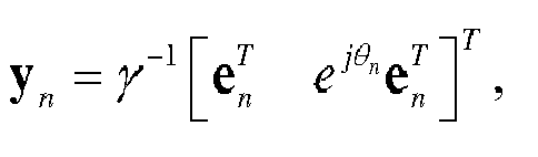
- An example in which a block matrix quantity NB = 2, and two block matrices X 1 Z 1 and X 2 Z 2 in W 1 Z separately have 4 columns is used, and the matrix W 2 may be:
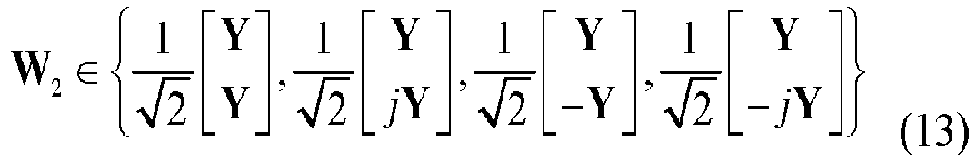


- An example in which a block matrix quantity NB = 2, and two block matrices X 1 Z 1 and X 2 Z 2 in W 1 Z separately have 8 columns is used, and the matrix W 2 may be:


- Specifically, the selecting, based on the reference signal, a precoding matrix from a codebook may include:
obtaining, by the user equipment UE based on the reference signal, channel estimation, and selecting the precoding matrix from the codebook according to the channel estimation and based on a predefined rule such as a rule of maximizing a channel capacity or a throughput, where selection, based on a predefined rule, of a precoding matrix is the prior art, and is not described in detail herein. - Step 103: Send a precoding matrix indicator PMI to the base station according to the selected precoding matrix w , where the PMI is used by the base station to obtain the selected precoding matrix W according to the PMI.
- Specifically, the precoding matrix w is included in a precoding matrix set or a codebook, and the PMI is used to indicate the precoding matrix w selected from the precoding matrix set or the codebook.
- Specifically, the sending a precoding matrix indicator PMI to the base station includes: sending the precoding matrix indicator PMI to the base station, where the PMI may only include a specific value, and in this case, the PMI directly indicates the precoding matrix w . For example, there are a total of 16 different precoding matrices, and PMI = 0, ..., 15 may be used to respectively indicate precoding matrices W marked as 0, 1, ..., 15.
- Specifically, the sending a precoding matrix indicator PMI to the base station may also include: sending precoding matrix indicators PMI1 and PMI2 to the base station, where the PMI1 and the PMI2 are respectively used to indicate the matrix W 1 Z and the matrix W 2 in formula (1), and in this case, the matrix W 1 Z and the matrix W 2 are respectively indicated by the PMI1 and the PMI2 in the codebook;
or
the sending a precoding matrix indicator PMI to the base station may also include: sending a third precoding matrix indicator PMI3 and a fourth precoding matrix indicator PMI4 to the base station, where the PMI3 is used to indicate the matrix W 1, and the PMI4 is used to indicate the matrix ZW2 ;
or
sending the second precoding matrix indicator PMI2, the third precoding matrix indicator PMI3, and a fifth precoding matrix indicator PMI5 to the base station, where the PMI5 is used to indicate Z - Further, the precoding matrix indicators PMI1 and PMI2, or PMI3 and PMI4, or PMI2, PMI3, and PMI5 have different time domains or frequency domain granularities. Specifically, the sending a precoding matrix indicator PMI to the base station specifically includes:
- sending the PMI1 to the base station according to a first period; and
- sending the PMI2 to the base station according to a second period, where the first period is greater than the second period; or
- sending the PMI3 to the base station according to a third period; and
- sending the PMI4 to the base station according to a fourth period, where the third period is greater than the fourth period; or
- sending the PMI2 to the base station according to a second period;
- sending the PMI3 to the base station according to a third period; and
- sending the PMI5 to the base station according to a fifth period, where the third period is less than the second period and the fifth period;
- or, sending the PMI1 to the base station according to a first frequency domain granularity; and
- sending the PMI2 to the base station according to a second frequency domain granularity, where the first frequency domain granularity is greater than the second frequency domain granularity, for example, sending a wideband PMI1 and a sub-band PMI2 to the base station; or
- sending the PMI3 to the base station according to a third frequency domain granularity; and
- sending the PMI4 to the base station according to a fourth frequency domain granularity, where the third frequency domain granularity is greater than the fourth frequency domain granularity, for example, sending a wideband PMI3 and a sub-band PMI4 to the base station; or
- sending the PMI2 to the base station according to a second frequency domain granularity;
- sending the PMI3 to the base station according to a third frequency domain granularity; and
- sending the PMI5 to the base station according to a fifth frequency domain granularity, where the third frequency domain granularity is less than the second frequency domain granularity and the fifth frequency domain granularity, for example, sending a wideband PMI2, a wideband PMI5, and a sub-band PMI3 to the base station.
- It should be noted that, the sizes of the foregoing wideband and sub-band may vary with the size of a system bandwidth. For example, in a 10 MHz LTE system that includes 50 physical resource blocks (Resource Block, RB), the wideband may include 50 RBs, and the size of the sub-band may be 6 consecutive RBs; and in a 5 MHz LTE system, the wideband may include 25 RBs, and the size of the sub-band may be 3 consecutive RBs.
- For the foregoing different time domains, or frequency domain granularities, or reporting periods, feedback overheads can be further reduced by using time or frequency domain relevance between channels.
- Specifically, the sending a precoding matrix indicator PMI to the base station may also include: sending a precoding matrix indicator PMI1i, where 1 ≤ i ≤ NB, and the PMI2 to the base station; PMIi, where 1 ≤ i ≤ NB, and the PMI2 are respectively used to indicate the matrix X i Z i , where 1 ≤ i ≤ NB, and the matrix W2 ;
or sending a precoding matrix indicator PMI3i, where 1 ≤ i ≤ NB, and the PMI4 to the base station; PMI3i, where 1 ≤ i ≤ NB, is used to indicate X i and the PMI4 is used to indicate the matrix ZW2 ;
or sending a precoding matrix indicator PMI3i, where 1 ≤ i ≤ NB, the PMI2, and the PMI5 to the base station, where the PMI5 is used to indicate Z . - Specifically, the sending a precoding matrix indicator PMI to the base station may also include: sending a precoding matrix indicator PMI5i, where 1 ≤ i ≤ NB /2, and the PMI2 to the base station; PMI5i, where 1 ≤ i ≤ NB /2, and the PMI2 are respectively used to indicate the matrix X 2i-1 Z 2i-1 = X 2i Z 2i , where 1 ≤ i ≤ NB /2, and the matrix W2 ; and in this case, X 2i-1 Z 2i-1 = X 2i Z 2i and the two matrices appear in pairs.
- Specifically, the sending a precoding matrix indicator PMI to the base station may be: sending, by the UE, the precoding matrix indicator PMI to the base station through a physical uplink control channel (Physical Uplink Control Channel, PUCCH) or a physical uplink shared channel (Physical Uplink Shared Channel, PUSCH).
- Further, the sending a precoding matrix indicator PMI to the base station may be: separately sending, by the UE to the base station by using different subframes or in different periods, the PMI1 and the PMI2, or the PMI3 and the PMI4, or the PMI2, the PMI3, and the PMI5, or the PMI1i, where 1 ≤ i ≤ NB, and the PMI2, or the PMI3,i and the PMI4, or the PMI3i, where 1 ≤ i ≤ NB, the PMI2, and the PMI5, or the PMI5i, where 1 ≤ i ≤ NB /2, and the PMI2.
- Further, the sending a precoding matrix indicator PMI to the base station may also be: separately sending, by the UE to the base station according to different sub-bands or sub-band widths in a frequency domain, the PMI1 and the PMI2, or the PMI3 and the PMI4, or the PMI2, the PMI3, and the PMI5, or the PMI1i, where 1 ≤ i ≤ NB, and the PMI2, or the PMI3,i and the PMI4, or the PMI3i, where 1 ≤ i ≤ NB, the PMI2, and the PMI5, or the PMI5i, where 1 ≤ i ≤ NB /2, and the PMI2.
- In addition, multiple block matrices X i may separately correspond to antenna groups of different polarizations or different locations; therefore, the precoding matrix can match multiple antenna deployments or configurations. The foregoing codebook structure can significantly improve performance of MIMO, especially MU-MIMO.
- In addition, one or more PMIs are fed back based on a subset, to indicate the precoding matrix; therefore, time/frequency domain/space relevance between channels is fully used, thereby significantly reducing feedback overheads.
- Further, as shown in
FIG. 2 , after thestep 201 of receiving a reference signal sent by a base station, the selecting, based on the reference signal, a precoding matrix from a codebook is specifically:
202: Select, based on the reference signal, the precoding matrix from a codebook subset. - The codebook subset may be a predefined codebook subset; or may be a codebook subset as follows: the codebook subset is reported by the UE to the base station eNB, determined by the base station eNB based on a report of the UE, and then told by the base station to the UE; or may be a codebook subset that is determined and reported by the UE, for example, a recently reported codebook subset.
- Further, the codebook subset and another codebook subset share at least one same matrix subset of the following matrix subsets: subsets of a matrix W 1, a matrix W 1 Z, a matrix W 2, a matrix ZW 2, and a matrix Z .
- As described above, the precoding matrix is selected based on the codebook subset, which can further reduce feedback overheads and implementation complexity.
- Further, the codebook subsets share a same subset of the matrix W 1, or the matrix W 1 Z, or the matrix W 2, or the matrix ZW 2, or the matrix Z, and therefore, the codebook subsets overlap with each other, which can overcome an edge effect of quantization of channel state information.
- Further, in the precoding matrix, the block matrices X i of the block diagonal matrix W 1 may be unequal, or may be equal. If the block diagonal matrix W 1 has multiple equal block matrices, for example, equal block matrices may appear in pairs, feedback overheads can be further reduced.
- It should be noted that, the three matrices W 1, Z, and W 2 included in the precoding matrix w that is selected, based on the reference signal, from the codebook may further be multiplied by a scale factor, so as to implement power normalization or power balancing. In addition, apart from the precoding matrix having the foregoing structure, the codebook may further include other precoding matrices, so as to meet requirements of other scenarios, which is not limited herein.
- This embodiment of the present invention provides the method for reporting channel state information. The method includes: after receiving reference information sent by a base station, selecting, by user equipment based on the reference information, a precoding matrix from a codebook, where a precoding matrix w included in the codebook is a product of three matrices being W 1, Z, and W 2 where both W 1 and Z are block diagonal matrices, W 1=diag{X 1,...,X N
B }, Z=diag{Z 1,...,Z NB ], each of W 1 and Z includes at least one block matrix, that is, NB ≥ 1, and each column of each block matrix Z i in the matrix Z has the following structure:

- This embodiment of the present invention further provides a method for reporting channel state information. The method is executed by a base station, and as shown in
FIG. 3 , the method includes: - 301: Send a reference signal to user equipment UE.
- 302: Receive a precoding matrix indicator PMI sent by the UE.
- 303: Determine a precoding matrix w in a codebook according to the PMI, where the precoding matrix w is a product of three matrices being W 1, Z, and W 2, that is, W = W 1 ZW 2, where
both W 1 and Z are block diagonal matrices, W 1=diag{X 1,...,X NB }, Z=diag{Z 1,...,Z NB }, each of W 1 and Z includes at least one block matrix, that is, NB ≥ 1, and each column of each block matrix Z i in the matrix Z has the following structure:
- It should be noted that, apart from the precoding matrix having the foregoing structure, the codebook may further include other precoding matrices, so as to meet requirements of other scenarios, which is not limited herein.
- In this embodiment of the present invention, user equipment determines and sends a precoding matrix indicator PMI, where the PMI indicates a precoding matrix, and the precoding matrix has a structure: W = W 1 ZW 2, where both W 1 and Z are block diagonal matrices, and each column of each block matrix Z i in the matrix Z has a structure:
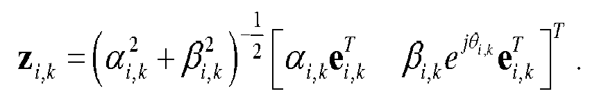
- Based on the methods for reporting channel state information provided in the foregoing embodiments, the following describes in detail interaction between devices for implementing a method for reporting channel state information provided in this embodiment of the present invention, and as shown in
FIG. 4 , the method includes: - 401: A base station sends a reference signal to user equipment UE.
- 402: The user equipment receives the reference signal sent by the base station.
- 403: The user equipment selects, based on the reference signal, a precoding matrix from a codebook, where a precoding matrix w included in the codebook is a product of three matrices being W 1, Z, and W 2, that is, W = W 1 ZW 2, where
both W 1 and Z are block diagonal matrices, W 1=diag{X 1,...,X NB }, Z=diag{Z 1,...,Z NB }, each of W 1 and Z includes at least one block matrix, that is, NB ≥ 1, and each column of each block matrix Z i in the matrix Z has the following structure:
- 404: The user equipment sends a precoding matrix indicator PMI to the base station, where the PMI corresponds to the selected precoding matrix, and is used by the base station to obtain the selected precoding matrix w according to the PMI.
- 405: The base station receives the precoding matrix indicator PMI sent by the UE.
- 406: Determine the precoding matrix w in the codebook according to the PMI.
- In this embodiment of the present invention, user equipment determines and sends a precoding matrix indicator PMI, where the PMI indicates a precoding matrix, and the precoding matrix has a structure: W = W 1 ZW 2, where both W 1 and Z are block diagonal matrices, and each column of each block matrix Z i in the matrix Z has a structure:

- This embodiment of the present invention provides user equipment. As shown in
FIG. 5 , the user equipment includes: a receivingunit 51, aselection unit 52, and a sendingunit 53. - The receiving
unit 51 is configured to receive a reference signal sent by a base station. - The
selection unit 52 is configured to select, based on the reference signal, a precoding matrix from a codebook, where a precoding matrix w included in the codebook is a product of three matrices being W 1, Z, and W 2, that is, W = W 1 ZW 2, where
both W 1 and Z are block diagonal matrices, W 1=diag{X 1,...,X NB }, Z=diag{Z 1,...,Z NB }, each of W 1 and Z includes at least one block matrix, that is, NB ≥ 1, and each column of each block matrix Z i in the matrix Z has the following structure:
- The sending
unit 53 is configured to send a precoding matrix indicator PMI to the base station, where the PMI corresponds to the selected precoding matrix, and is used by the base station to obtain the selected precoding matrix w according to the PMI. - Optionally, the
selection unit 52 is specifically configured to select, based on the reference signal, the precoding matrix from a codebook subset, where the codebook subset is a subset predefined, or notified by the base station, or determined by the user equipment. - Preferably, the codebook subsets share at least one same matrix subset of the following matrix subsets: subsets of a matrix W 1, a matrix W1Z, a matrix W 2, a matrix ZW 2, and a matrix Z.
- Optionally, the sending
unit 53 may be specifically configured to send a first precoding matrix indicator PMI1 and a second precoding matrix indicator PMI2 to the base station, where the PMI1 is used to indicate the matrix W1Z, and the PMI2 is used to indicate the matrix W2 ; or
send a third precoding matrix indicator PMI3 and a fourth precoding matrix indicator PMI4 to the base station, where the PMI3 is used to indicate the matrix W 1, and the PMI4 is used to indicate the matrix ZW2 ; or
send the second precoding matrix indicator PMI2, the third precoding matrix indicator PMI3, and a fifth precoding matrix indicator PMI5 to the base station, where the PMI5 is used to indicate Z - Optionally, the sending
unit 53 may be specifically configured to send the PMI1 to the base station according to a first period; and
send the PMI2 to the base station according to a second period, where the first period is greater than the second period; or
send the PMI3 to the base station according to a third period; and
send the PMI4 to the base station according to a fourth period, where the third period is greater than the fourth period; or
send the PMI2 to the base station according to a second period;
send the PMI3 to the base station according to a third period; and
send the PMI5 to the base station according to a fifth period, where the third period is less than the second period and the fifth period. - The sending
unit 53 may further be specifically configured to send the PMI1 to the base station according to a first frequency domain granularity; and
send the PMI2 to the base station according to a second frequency domain granularity, where the first frequency domain granularity is greater than the second frequency domain granularity, for example, send a wideband PMI1 and a sub-band PMI2 to the base station; or
send the PMI3 to the base station according to a third frequency domain granularity; and
send the PMI4 to the base station according to a fourth frequency domain granularity, where the third frequency domain granularity is greater than the fourth frequency domain granularity, for example, send a wideband PMI3 and a sub-band PMI4 to the base station; or
send the PMI2 to the base station according to a second frequency domain granularity;
send the PMI3 to the base station according to a third frequency domain granularity; and
send the PMI5 to the base station according to a fifth frequency domain granularity, where the third frequency domain granularity is less than the second frequency domain granularity and the fifth frequency domain granularity, for example, send a wideband PMI2, a wideband PMI5, and a sub-band PMI3 to the base station. - It should be noted that, the sizes of the foregoing wideband and sub-band may vary with the size of a system bandwidth. For example, in a 10 MHz LTE system, the wideband may include 50 physical resource blocks RBs, and the size of the sub-band may be 6 consecutive RBs; and in a 5 MHz LTE system, the wideband may include 25 RBs, and the size of the sub-band may be 3 consecutive RBs.
- Optionally, the block matrix X i =[X i,1 X i,2], where each column of the matrix X i,j is selected from columns of a Householder matrix, a discrete Fourier transform matrix, a Hadamard matrix, a rotated Hadamard matrix, or a precoding matrix in an LTE R8 system 2-antenna or 4-antenna codebook or in an LTE RIO system 8-antenna codebook.
- Further, each column of the matrix X i,j , j = 1, 2 is separately selected from columns of different Householder matrices, different discrete Fourier transform matrices, different Hadamard matrices, different rotated Hadamard matrices, or different precoding matrices in an LTE R8 system 2-antenna or 4-antenna codebook or in an LTE R10 system 8-antenna codebook.
- Optionally, the block matrix X i =[X i,1 X i,2], where the matrix X i,j is a Kronecker product of two matrices being A i,j and B i,j , and j = 1, 2.
- Further, columns of the matrix X i,1 and the matrix X i,2 are column vectors of a Householder matrix, a discrete Fourier transform matrix, a Hadamard matrix, a rotated Hadamard matrix, or a precoding matrix in an LTE R8 system 2-antenna or 4-antenna codebook or in an LTE R10 system 8-antenna codebook.
- Optionally, W 1 is an identity matrix.
- Optionally, a column vector in the matrix W 2 has a structure:

- This embodiment of the present invention further provides user equipment. As shown in
FIG. 6 , the user equipment includes: atransceiver 601, amemory 602, and aprocessor 603. Certainly, the user equipment may further include common-purpose components such as an antenna and an input output apparatus, which is not limited herein in this embodiment of the present invention. - The
memory 602 stores a set of program code, and theprocessor 603 is configured to invoke the program code stored in thememory 602, to perform the following operations: receiving, by using thetransceiver 601, a reference signal sent by a base station; selecting, based on the reference signal, a precoding matrix from a codebook, where a precoding matrix w included in the codebook is a product of three matrices being W1 , Z, and W2 , that is, W = W1ZW2, where
both W1 and Z are block diagonal matrices, W1 =diag{X 1,...,X NB }, Z=diag{Z 1,...,Z NB }, each of W1 and Z includes at least one block matrix, that is, NB ≥ 1, and each column of each block matrix Z i in the matrix Z has the following structure:
transceiver 601, where the PMI corresponds to the selected precoding matrix, and is used by the base station to obtain the selected precoding matrix w according to the PMI. - The selecting, based on the reference signal, a precoding matrix from a codebook specifically includes:
selecting, based on the reference signal, the precoding matrix from a codebook subset, where the codebook subset is a subset predefined, or notified by the base station, or reported by the user equipment. - Optionally, the codebook subsets share at least one same matrix subset of the following matrix subsets: subsets of a matrix W 1, a matrix W1Z, a matrix W2 , a matrix ZW2 , and a matrix Z.
- Optionally, the sending a precoding matrix indicator PMI to the base station by using the transceiver 61 specifically includes:
- sending a first precoding matrix indicator PMI1 and a second precoding matrix indicator PMI2 to the base station, where the PMI1 is used to indicate the matrix W1Z, and the PMI2 is used to indicate the matrix W2 ; or
- sending a third precoding matrix indicator PMI3 and a fourth precoding matrix indicator PMI4 to the base station, where the PMI3 is used to indicate the matrix W 1, and the PMI4 is used to indicate the matrix ZW2 ; or
- sending the second precoding matrix indicator PMI2, the third precoding matrix indicator PMI3, and a fifth precoding matrix indicator PMI5 to the base station, where the PMI5 is used to indicate Z.
- Optionally, the sending a precoding matrix indicator PMI to the base station by using the transceiver 61 specifically includes:
- sending the PMI1 to the base station according to a first period; and
- sending the PMI2 to the base station according to a second period, where the first period is greater than the second period; or
- sending the PMI3 to the base station according to a third period; and
- sending the PMI4 to the base station according to a fourth period, where the third period is greater than the fourth period; or
- sending the PMI2 to the base station according to a second period;
- sending the PMI3 to the base station according to a third period; and
- sending the PMI5 to the base station according to a fifth period, where the third period is less than the second period and the fifth period.
- Optionally, the sending a precoding matrix indicator PMI to the base station by using the transceiver 61 specifically includes:
- sending the PMI1 to the base station according to a first frequency domain granularity; and
- sending the PMI2 to the base station according to a second frequency domain granularity, where the first frequency domain granularity is greater than the second frequency domain granularity, for example, sending a wideband PMI1 and a sub-band PMI2 to the base station; or
- sending the PMI3 to the base station according to a third frequency domain granularity; and
- sending the PMI4 to the base station according to a fourth frequency domain granularity, where the third frequency domain granularity is greater than the fourth frequency domain granularity, for example, sending a wideband PMI3 and a sub-band PMI4 to the base station; or
- sending the PMI2 to the base station according to a second frequency domain granularity;
- sending the PMI3 to the base station according to a third frequency domain granularity; and
- sending the PMI5 to the base station according to a fifth frequency domain granularity, where the third frequency domain granularity is less than the second frequency domain granularity and the fifth frequency domain granularity, for example, sending a wideband PMI2, a wideband PMI5, and a sub-band PMI3 to the base station.
- It should be noted that, the sizes of the foregoing wideband and sub-band may vary with the size of a system bandwidth. For example, in a 10 MHz LTE system, the wideband may include 50 physical resource blocks RBs, and the size of the sub-band may be 6 consecutive RBs; and in a 5 MHz LTE system, the wideband may include 25 RBs, and the size of the sub-band may be 3 consecutive RBs.
- Optionally, the block matrix X i =[X i,1 X i,2], where each column of the matrix X i,j is selected from columns of a Householder matrix, a discrete Fourier transform matrix, a Hadamard matrix, a rotated Hadamard matrix, or a precoding matrix in an LTE R8 system 2-antenna or 4-antenna codebook or in an LTE RIO system 8-antenna codebook.
- Further, each column of the matrix X i,j , j = 1, 2 is separately selected from columns of different Householder matrices, different discrete Fourier transform matrices, different Hadamard matrices, different rotated Hadamard matrices, or different precoding matrices in an LTE R8 system 2-antenna or 4-antenna codebook or in an LTE RIO system 8-antenna codebook.
- Optionally, the block matrix X i =[X i,1 X i,2], where the matrix X i,j is a Kronecker product of two matrices being A i,j and B i,j , and j = 1, 2.
- Further, columns of the matrix X i,1 and the matrix X i,2 are column vectors of a Householder matrix, a discrete Fourier transform matrix, a Hadamard matrix, a rotated Hadamard matrix, or a precoding matrix in an LTE R8 system 2-antenna or 4-antenna codebook or in an LTE R10 system 8-antenna codebook.
- Optionally, W1 is an identity matrix.
- Optionally, a column vector in the matrix W2 has a structure:

- It should be noted that, apart from the precoding matrix having the foregoing structure, the codebook may further include other precoding matrices, so as to meet requirements of other scenarios, which is not limited herein.
- In this embodiment of the present invention, user equipment determines and sends a precoding matrix indicator PMI, where the PMI indicates a precoding matrix, and the precoding matrix has a structure: W = W1ZW2, where both W1 and Z are block diagonal matrices, and each column of each block matrix Z i in the matrix Z has a structure:

- This embodiment of the present invention provides a base station. As shown in
FIG. 7 , the base station includes: a sendingunit 71, a receivingunit 72, and a determiningunit 73. - The sending
unit 71 is configured to send a reference signal to user equipment UE. - The receiving
unit 72 is configured to receive a precoding matrix indicator PMI sent by the UE. - The determining
unit 73 is configured to determine a precoding matrix w in a codebook according to the PMI, where the precoding matrix w is a product of three matrices being W1 , Z, and W2 , that is, W = W1ZW2, where
both W1 and Z are block diagonal matrices, W1 =diag{X 1,...,X NB } Z=diag{Z 1,...,Z NB }, each of W1 and Z includes at least one block matrix, that is, NB ≥ 1, and each column of each block matrix Z i in the matrix Z has the following structure: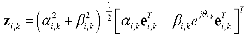
- Optionally, the determining
unit 73 is specifically configured to determine the precoding matrix in a codebook subset according to the PMI, where the codebook subset is a subset predefined, or reported by the user equipment, or determined by the base station. - The codebook subsets share at least one same matrix subset of the following matrix subsets: subsets of a matrix W 1, a matrix W1Z, a matrix W2 , a matrix ZW2 , and a matrix Z.
- Optionally, the receiving
unit 72 is specifically configured to: - receive a first precoding matrix indicator PMI1 and a second precoding matrix indicator PMI2 that are sent by the UE, where the PMI1 is used to indicate the matrix W1Z, and the PMI2 is used to indicate the matrix W2 ;
- or
- receive a third precoding matrix indicator PMI3 and a fourth precoding matrix indicator PMI4 that are sent by the UE, where the PMI3 is used to indicate the matrix W 1, and the PMI4 is used to indicate the matrix ZW2 ;
- or
- receive the second precoding matrix indicator PMI2, the third precoding matrix indicator PMI3, and a fifth precoding matrix indicator PMI5 that are sent by the UE, where the PMI5 is used to indicate Z
- Optionally, the receiving
unit 72 is specifically configured to: - receive, according to a first period, the PMI1 sent by the UE; and
- receive, according to a second period, the PMI2 sent by the UE, where the first period is greater than the second period; or
- receive, according to a third period, the PMI3 sent by the UE; and
- receive, according to a fourth period, the PMI4 sent by the UE, where the third period is greater than the fourth period; or
- receive, according to a second period, the PMI2 sent by the UE;
- receive, according to a third period, the PMI3 sent by the UE; and
- receive, according to a fifth period, the PMI5 sent by the UE, where the third period is less than the second period and the fifth period.
- Optionally, the receiving
unit 72 is specifically configured to: - receive, according to a first frequency domain granularity, the PMI1 sent by the UE; and
- receive, according to a second frequency domain granularity, the PMI2 sent by the UE, where the first frequency domain granularity is greater than the second frequency domain granularity, for example, a wideband PMI1 and a sub-band PMI2 are sent to the base station; or receive, according to a third frequency domain granularity, the PMI3 sent by the UE; and
- receive, according to a fourth frequency domain granularity, the PMI4 sent by the UE, where the third frequency domain granularity is greater than the fourth frequency domain granularity, for example, a wideband PMI3 and a sub-band PMI4 are sent to the base station; or
- receive, according to a second frequency domain granularity, the PMI2 sent by the UE;
- receive, according to a third frequency domain granularity, the PMI3 sent by the UE; and
- receive, according to a fifth frequency domain granularity, the PMI5 sent by the UE, where the third frequency domain granularity is less than the second frequency domain granularity and the fifth frequency domain granularity, for example, a wideband PMI2, a wideband PMI5, and a sub-band PMI3 are sent to the base station.
- It should be noted that, the sizes of the foregoing wideband and sub-band may vary with the size of a system bandwidth. For example, in a 10 MHz LTE system, the wideband may include 50 physical resource blocks RBs, and the size of the sub-band may be 6 consecutive RBs; and in a 5 MHz LTE system, the wideband may include 25 RBs, and the size of the sub-band may be 3 consecutive RBs.
- Optionally, the block matrix X i =[X i,1 X i,2], where each column of the matrix X i,j is selected from columns of a Householder matrix, a discrete Fourier transform matrix, a Hadamard matrix, a rotated Hadamard matrix, or a precoding matrix in an LTE R8 system 2-antenna or 4-antenna codebook or in an LTE RIO system 8-antenna codebook.
- Further, each column of the matrix X i,j is separately selected from columns of different Householder matrices, different discrete Fourier transform matrices, different Hadamard matrices, different rotated Hadamard matrices, or different precoding matrices in an LTE R8 system 2-antenna or 4-antenna codebook or in an LTE R10 system 8-antenna codebook.
- Optionally, the block matrix X i = [X i,1 X i,2], where the matrix X i,j is a Kronecker product of two matrices being A i,j and B i,j , and j = 1, 2.
- Specifically, columns of the matrix X i,1 and the matrix X i,2 are column vectors of a Householder matrix, a discrete Fourier transform matrix, a Hadamard matrix, a rotated Hadamard matrix, or a precoding matrix in an LTE R8 system 2-antenna or 4-antenna codebook or in an LTE R10 system 8-antenna codebook.
- Optionally, W1 is an identity matrix.
- Optionally, a column vector in the matrix W2 has a structure:

- This embodiment of the present invention further provides a base station. As shown in
FIG. 8 , the base station includes: atransceiver 801, amemory 802, and aprocessor 803. Certainly, the base station may further include common-purpose components such as an antenna and an input/output apparatus, which is not limited herein in this embodiment of the present invention. - The
memory 802 stores a set of program code, and theprocessor 803 is configured to invoke the program code stored in thememory 802, to perform the following operations:
sending a reference signal to user equipment UE by using thetransceiver 801; when the user equipment reports a PMI, receiving, by using thetransceiver 801, the precoding matrix indicator PMI sent by the UE; and determining a precoding matrix w in a codebook according to the PMI, where the precoding matrix w is a product of three matrices being W1 , Z, and W2 , that is, W = W1ZW2, where
both W1 and Z are block diagonal matrices, W1 =diag{X 1,...,X NB }, Z=diag{Z 1,...,Z NB }, each of W1 and Z includes at least one block matrix, that is, NB ≥ 1, and each column of each block matrix Z i in the matrix Z has the following structure: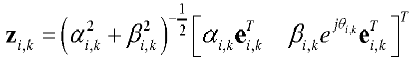
- The determining a precoding matrix w in a codebook according to the PMI specifically includes: determining the precoding matrix in a codebook subset according to the PMI, where the codebook subset is a subset predefined, or reported by the user equipment, or determined by the base station.
- The codebook subsets share at least one same matrix subset of the following matrix subsets: subsets of a matrix W 1, a matrix W 1 Z, a matrix W2 , a matrix ZW2 , and a matrix Z.
- The receiving the PMI by using the transceiver 81 may specifically include: receiving a first precoding matrix indicator PMI1 and a second precoding matrix indicator PMI2 that are sent by the UE, where the PMI1 is used to indicate the matrix W1Z, and the PMI2 is used to indicate the matrix W2 ;
or
receiving a third precoding matrix indicator PMI3 and a fourth precoding matrix indicator PMI4 that are sent by the UE, where the PMI3 is used to indicate the matrix W 1, and the PMI4 is used to indicate the matrix ZW2 ;
or
receiving the second precoding matrix indicator PMI2, the third precoding matrix indicator PMI3, and a fifth precoding matrix indicator PMI5 that are sent by the UE, where the PMI5 is used to indicate Z. - The receiving the PMI by using the transceiver 81 may specifically include: receiving, according to a first period, the PMI1 sent by the UE; and
receiving, according to a second period, the PMI2 sent by the UE, where the first period is greater than the second period; or
receiving, according to a third period, the PMI3 sent by the UE; and
receiving, according to a fourth period, the PMI4 sent by the UE, where the third period is greater than the fourth period; or
receiving, according to a second period, the PMI2 sent by the UE;
receiving, according to a third period, the PMI3 sent by the UE; and
receiving, according to a fifth period, the PMI5 sent by the UE, where the third period is less than the second period and the fifth period. - The receiving the PMI by using the transceiver 81 may further specifically include: receiving, according to a first frequency domain granularity, the PMI1 sent by the UE; and
receiving, according to a second frequency domain granularity, the PMI2 sent by the UE, where the first frequency domain granularity is greater than the second frequency domain granularity, for example, receiving a wideband PMI1 and a sub-band PMI2 that are sent by the UE; or
receiving, according to a third frequency domain granularity, the PMI3 sent by the UE; and
receiving, according to a fourth frequency domain granularity, the PMI4 sent by the UE, where the third frequency domain granularity is greater than the fourth frequency domain granularity, for example, receiving a wideband PMI3 and a sub-band PMI4 that are sent by the UE; or
receiving, according to a second frequency domain granularity, the PMI2 sent by the UE;
receiving, according to a third frequency domain granularity, the PMI3 sent by the UE; and
receiving, according to a fifth frequency domain granularity, the PMI5 sent by the UE, where the third frequency domain granularity is less than the second frequency domain granularity and the fifth frequency domain granularity, for example, receiving a wideband PMI2, a wideband PMI5, and a sub-band PMI3 that are sent by the UE. - It should be noted that, the sizes of the foregoing wideband and sub-band may vary with the size of a system bandwidth. For example, in a 10 MHz LTE system, the wideband may include 50 physical resource blocks RBs, and the size of the sub-band may be 6 consecutive RBs; and in a 5 MHz LTE system, the wideband may include 25 RBs, and the size of the sub-band may be 3 consecutive RBs.
- The block matrix X i =[X i,1 X i,2], where each column of the matrix X i,j is selected from columns of a Householder matrix, a discrete Fourier transform matrix, a Hadamard matrix, a rotated Hadamard matrix, or a precoding matrix in an LTE R8 system 2-antenna or 4-antenna codebook or in an LTE RIO system 8-antenna codebook.
- Further, each column of the matrix X i,j is separately selected from columns of different Householder matrices, different discrete Fourier transform matrices, different Hadamard matrices, different rotated Hadamard matrices, or different precoding matrices in an LTE R8 system 2-antenna or 4-antenna codebook or in an LTE RIO system 8-antenna codebook.
- Optionally, the block matrix X i =[X i,1 X i,2], where the matrix X i,j is a Kronecker product of two matrices being A i,j and B i,j , and j = 1, 2.
- Specifically, columns of the matrix X i,1 and the matrix X i,2 are column vectors of a Householder matrix, a discrete Fourier transform matrix, a Hadamard matrix, a rotated Hadamard matrix, or a precoding matrix in an LTE R8 system 2-antenna or 4-antenna codebook or in an LTE RIO system 8-antenna codebook.
- Optionally, W1 is an identity matrix.
- Optionally, a column vector in the matrix W2 has a structure:

- It should be noted that, apart from the precoding matrix having the foregoing structure, the codebook may further include other precoding matrices, so as to meet requirements of other scenarios, which is not limited herein.
- In this embodiment of the present invention, after receiving a precoding matrix indicator PMI reported by user equipment, a base station determines a precoding matrix according to the PMI, where the precoding matrix has a structure: W = W1ZW2, where both W1 and Z are block diagonal matrices, and each column of each block matrix Z i in the matrix Z has a structure:

- It should be noted that, for specific descriptions of some function modules in the base station and the user equipment that are provided in the embodiments of the present invention, reference may be made to corresponding content in the method embodiments, and details are not described again in this embodiment.
- As seen from the descriptions of the foregoing embodiments, it may be clearly understood by a person skilled in the art that, for the purpose of convenient and brief description, division of the foregoing function modules is used as an example for illustration. In actual application, the foregoing functions can be allocated to different function modules and implemented according to a requirement, that is, an inner structure of an apparatus is divided into different function modules to implement all or some of the functions described above. For a detailed working process of the foregoing system, apparatus, and unit, reference may be made to a corresponding process in the foregoing method embodiments, and details are not described herein again.
- In the several embodiments provided in the present application, it should be understood that the disclosed system, apparatus, and method may be implemented in other manners. For example, the described apparatus embodiment is merely exemplary. For example, the module or unit division is merely logical function division and may be other division in actual implementation. For example, a plurality of units or components may be combined or integrated into another system, or some features may be ignored or not performed. In addition, the displayed or discussed mutual couplings or direct couplings or communication connections may be implemented through some interfaces. The indirect couplings or communication connections between the apparatuses or units may be implemented in electronic, mechanical, or other forms.
- The units described as separate parts may or may not be physically separate, and parts displayed as units may or may not be physical units, may be located in one position, or may be distributed on a plurality of network units. Some or all of the units may be selected according to actual needs to achieve the objectives of the solutions of the embodiments.
- In addition, functional units in the embodiments of the present invention may be integrated into one processing unit, or each of the units may exist alone physically, or two or more units are integrated into one unit. The integrated unit may be implemented in a form of hardware, or may be implemented in a form of a software functional unit.
- When the integrated unit is implemented in the form of a software functional unit and sold or used as an independent product, the integrated unit may be stored in a computer-readable storage medium. Based on such an understanding, the technical solutions of the present invention essentially, or the part contributing to the prior art, or all or some of the technical solutions may be implemented in the form of a software product. The software product is stored in a storage medium and includes several instructions for instructing a computer device (which may be a personal computer, a server, or a network device) or a processor to perform all or some of the steps of the methods described in the embodiments of the present invention. The foregoing storage medium includes: any medium that can store program code, such as a USB flash drive, a removable hard disk, a read-only memory (ROM, Read-Only Memory), a random access memory (RAM, Random Access Memory), a magnetic disk, or an optical disc.
- Embodiment 1. A method for reporting channel state information, wherein the method comprises:
- receiving a reference signal sent by a base station;
- selecting, based on the reference signal, a precoding matrix from a codebook, wherein the precoding matrix w comprised in the codebook is a product of three matrices being W 1, Z, and W2 , that is, W = W1ZW2, wherein
both W1 and Z are block diagonal matrices, W1 =diag{X 1,...,X NB }, Z=diag{Z 1,...,Z NB }, each of W1 and Z comprises at least one block matrix, that is, NB ≥ 1, and each column of each block matrix Z i in the matrix Z has the following structure:

wherein [ ] T represents matrix transposition; e i,k represents an n i x1 selection vector, wherein in the vector, the kth element is 1 and all other elements are 0, and n i is a half of a column quantity of a block matrix X i ; θi,k is a phase shift, αi,k ≥ 0, and βi,k ≥ 0; and - sending a precoding matrix indicator PMI to the base station, wherein the PMI corresponds to the selected precoding matrix, and is used by the base station to obtain the selected precoding matrix W according to the PMI.
- Embodiment 2. The method according to embodiment 1, wherein the selecting, based on the reference signal, a precoding matrix from a codebook specifically comprises:
selecting, based on the reference signal, the precoding matrix from a codebook subset, wherein the codebook subset is a subset predefined, or notified by the base station, or reported by user equipment. - Embodiment 3. The method according to embodiment 2, wherein the codebook subsets share at least one same matrix subset of the following matrix subsets: subsets of a matrix W 1, a matrix W1Z, a matrix W2 , and a matrix ZW2 .
- Embodiment 4. The method according to any one of embodiments 1 to 3, wherein the sending a precoding matrix indicator PMI to the base station specifically comprises:
- sending a first precoding matrix indicator PMI1 and a second precoding matrix indicator PMI2 to the base station, wherein the PMI1 is used to indicate the matrix W1Z, and the PMI2 is used to indicate the matrix W2 ; or
- sending a third precoding matrix indicator PMI3 and a fourth precoding matrix indicator PMI4 to the base station, wherein the PMI3 is used to indicate the matrix W1 , and the PMI4 is used to indicate the matrix ZW2 ; or
- sending the second precoding matrix indicator PMI2, the third precoding matrix indicator PMI3, and a fifth precoding matrix indicator PMI5 to the base station, wherein the PMI5 is used to indicate Z.
- Embodiment 5. The method according to embodiment 4, wherein the sending a precoding matrix indicator PMI to the base station specifically comprises:
- sending the PMI1 to the base station according to a first period; and
- sending the PMI2 to the base station according to a second period, wherein the first period is greater than the second period; or
- sending the PMI3 to the base station according to a third period; and
- sending the PMI4 to the base station according to a fourth period, wherein the third period is greater than the fourth period; or
- sending the PMI2 to the base station according to a second period;
- sending the PMI3 to the base station according to a third period; and
- sending the PMI5 to the base station according to a fifth period, wherein the third period is less than the second period and the fifth period.
- Embodiment 6. The method according to embodiment 4, wherein the sending a precoding matrix indicator PMI to the base station specifically comprises:
- sending the PMI1 to the base station according to a first frequency domain granularity; and
- sending the PMI2 to the base station according to a second frequency domain granularity, wherein the first frequency domain granularity is greater than the second frequency domain granularity; or
- sending the PMI3 to the base station according to a third frequency domain granularity; and
- sending the PMI4 to the base station according to a fourth frequency domain granularity, wherein the third frequency domain granularity is greater than the fourth frequency domain granularity; or
- sending the PMI2 to the base station according to a second frequency domain granularity;
- sending the PMI3 to the base station according to a third frequency domain granularity; and
- sending the PMI5 to the base station according to a fifth frequency domain granularity, wherein the third frequency domain granularity is less than the second frequency domain granularity and the fifth frequency domain granularity.
- Embodiment 7. The method according to any one of embodiments 1 to 6, wherein the block matrix X i =[X i,1 X i,2], wherein each column of the matrix X i,j is selected from columns of a Householder matrix, a discrete Fourier transform matrix, a Hadamard matrix, a rotated Hadamard matrix, or a precoding matrix in an LTE R8 system 2-antenna or 4-antenna codebook or in an LTE R10 system 8-antenna codebook.
- Embodiment 8. The method according to embodiment 7, wherein each column of the matrix X i,j , j = 1, 2 is separately selected from columns of different Householder matrices, different discrete Fourier transform matrices, different Hadamard matrices, different rotated Hadamard matrices, or different precoding matrices in an LTE R8 system 2-antenna or 4-antenna codebook or in an LTE R10 system 8-antenna codebook.
- Embodiment 9. The method according to any one of embodiments 1 to 6, wherein the block matrix X i =[X i,1 X i,2], wherein the matrix X i,j is a Kronecker product of two matrices being A i,j and B i,j , and j = 1, 2.
- Embodiment 10. The method according to embodiment 9, wherein columns of the matrix X i,1 and the matrix X i,2 are column vectors of a Householder matrix, a discrete Fourier transform matrix, a Hadamard matrix, a rotated Hadamard matrix, or a precoding matrix in an LTE R8 system 2-antenna or 4-antenna codebook or in an LTE R10 system 8-antenna codebook.
- Embodiment 11. The method according to any one of embodiments 1 to 10, wherein W1 is an identity matrix.
- Embodiment 12. The method according to any one of embodiments 1 to 11, wherein a column vector in the matrix W2 has a structure

- Embodiment 13. A method for reporting channel state information, wherein the method comprises:
- sending a reference signal to user equipment UE;
- receiving a precoding matrix indicator PMI sent by the UE; and
- determining a precoding matrix w in a codebook according to the PMI, wherein the precoding matrix w is a product of three matrices being W 1, Z, and W 2, that is, W = W1ZW2, wherein
- both W1 and Z are block diagonal matrices, W1 =diag{X 1,...,X NB }, Z=diag{Z 1 ,..., Z N
B }, each of W1 and Z comprises at least one block matrix, that is, NB ≥ 1, and each column of each block matrix Z i in the matrix Z has the following structure:

wherein [ ] T represents matrix transposition; e i,k represents an n i x1 selection vector, wherein in the vector, the kth element is 1 and all other elements are 0, and n i is a half of a column quantity of a block matrix X i ; θi,k is a phase shift, αi,k ≥ 0 and βi,k ≥ 0.
- Embodiment 14. The method according to embodiment 13, wherein the determining a precoding matrix w in a codebook according to the PMI specifically comprises:
determining the precoding matrix in a codebook subset according to the PMI, wherein the codebook subset is a subset predefined, or reported by the user equipment, or determined by a base station. - Embodiment 15. The method according to embodiment 14, wherein the codebook subsets share at least one same matrix subset of the following matrix subsets: subsets of a matrix W 1, a matrix W1Z, a matrix W2 , a matrix ZW2 , and a matrix Z.
- Embodiment 16. The method according to any one of embodiments 13 to 15, wherein the receiving a precoding matrix indicator PMI sent by the UE specifically comprises:
- receiving a first precoding matrix indicator PMI1 and a second precoding matrix indicator PMI2 that are sent by the UE, wherein the PMI1 is used to indicate the matrix W1Z, and the PMI2 is used to indicate the matrix W2 ;
- or
- receiving a third precoding matrix indicator PMI3 and a fourth precoding matrix indicator PMI4 that are sent by the UE, wherein the PMI3 is used to indicate the matrix W 1, and the PMI4 is used to indicate the matrix ZW 2;
- or
- receiving the second precoding matrix indicator PMI2, the third precoding matrix indicator PMI3, and a fifth precoding matrix indicator PMI5 that are sent by the UE, wherein the PMI5 is used to indicate Z.
- Embodiment 17. The method according to embodiment 16, wherein the receiving a precoding matrix indicator PMI sent by the UE specifically comprises:
- receiving, according to a first period, the PMI1 sent by the UE; and
- receiving, according to a second period, the PMI2 sent by the UE, wherein the first period is greater than the second period; or
- receiving, according to a third period, the PMI3 sent by the UE; and
- receiving, according to a fourth period, the PMI4 sent by the UE, wherein the third period is greater than the fourth period; or
- receiving, according to a second period, the PMI2 sent by the UE;
- receiving, according to a third period, the PMI3 sent by the UE; and
- receiving, according to a fifth period, the PMI5 sent by the UE, wherein the third period is less than the second period and the fifth period.
- Embodiment 18. The method according to embodiment 16, wherein the receiving a precoding matrix indicator PMI sent by the UE specifically comprises:
- receiving, according to a first frequency domain granularity, the PMI1 sent by the UE; and
- receiving, according to a second frequency domain granularity, the PMI2 sent by the UE, wherein the first frequency domain granularity is greater than the second frequency domain granularity; or
- receiving, according to a third frequency domain granularity, the PMI3 sent by the UE; and
- receiving, according to a fourth frequency domain granularity, the PMI4 sent by the UE, wherein the third frequency domain granularity is greater than the fourth frequency domain granularity; or
- receiving, according to a second frequency domain granularity, the PMI2 sent by the UE;
- receiving, according to a third frequency domain granularity, the PMI3 sent by the UE; and
- receiving, according to a fifth frequency domain granularity, the PMI5 sent by the UE, wherein the third frequency domain granularity is less than the second frequency domain granularity and the fifth frequency domain granularity.
- Embodiment 19. The method according to any one of embodiments 13 to 18, wherein the block matrix X i =[X i,1 X i,2], wherein each column of the matrix X i,j is selected from columns of a Householder matrix, a discrete Fourier transform matrix, a Hadamard matrix, a rotated Hadamard matrix, or a precoding matrix in an LTE R8 system 2-antenna or 4-antenna codebook or in an LTE RIO system 8-antenna codebook.
- Embodiment 20. The method according to embodiment 19, wherein each column of the matrix X i,j is separately selected from columns of different Householder matrices, different discrete Fourier transform matrices, different Hadamard matrices, different rotated Hadamard matrices, or different precoding matrices in an LTE R8 system 2-antenna or 4-antenna codebook or in an LTE RIO system 8-antenna codebook.
- Embodiment 21. The method according to any one of embodiments 13 to 18, wherein the block matrix X i =[X i,1 X i,2], wherein the matrix X i,j is a Kronecker product of two matrices being A i,j and B i,j , and j = 1, 2.
- Embodiment 22. The method according to claim 21, wherein columns of the matrix X i,1 and the matrix X i,2 are column vectors of a Householder matrix, a discrete Fourier transform matrix, a Hadamard matrix, a rotated Hadamard matrix, or a precoding matrix in an LTE R8 system 2-antenna or 4-antenna codebook or in an LTE R10 system 8-antenna codebook.
- Embodiment 23. The method according to any one of embodiments 13 to 22, wherein W1 is an identity matrix.
- Embodiment 24. The method according to any one of embodiments 13 to 23, wherein a column vector in the matrix W2 has a structure

- Embodiment 25. User equipment, wherein the user equipment comprises: a receiving unit, a selection unit, and a sending unit, wherein
the receiving unit is configured to receive a reference signal sent by a base station;
the selection unit is configured to select, based on the reference signal, a precoding matrix from a codebook, wherein a precoding matrix W comprised in the codebook is a product of three matrices being W1 , Z, and W2 , that is, W = W1ZW2, wherein
both W1 and Z are block diagonal matrices, W 1=diag{X 1,...,X NB }, Z=diag{Z 1,...,Z NB }, each of W1 and Z comprises at least one block matrix, that is, NB ≥ 1, and each column of each block matrix Z i in the matrix Z has the following structure:

wherein [ ] T represents matrix transposition; e i,k represents an n i x1 selection vector, wherein in the vector, the kth element is 1 and all other elements are 0, and n i is a half of a column quantity of a block matrix X i ; θi,k is a phase shift, αi,k ≥ 0, and βi,k ≥ 0; and
the sending unit is configured to send a precoding matrix indicator PMI to the base station, wherein the PMI corresponds to the selected precoding matrix, and is used by the base station to obtain the selected precoding matrix W according to the PMI. - Embodiment 26. The user equipment according to embodiment 25, wherein the selection unit is specifically configured to select, based on the reference signal, the precoding matrix from a codebook subset, wherein the codebook subset is a subset predefined, or notified by the base station, or determined by the user equipment.
- Embodiment 27. The user equipment according to embodiment 26, wherein the codebook subsets share at least one same matrix subset of the following matrix subsets: subsets of a matrix W 1, a matrix W1Z, a matrix W 2, a matrix ZW2 , and a matrix Z.
- Embodiment 28. The user equipment according to any one of embodiments 25 to 27, wherein the sending unit is specifically configured to send a first precoding matrix indicator PMI1 and a second precoding matrix indicator PMI2 to the base station, wherein the PMI1 is used to indicate the matrix W1Z, and the PMI2 is used to indicate the matrix W 2; or
send a third precoding matrix indicator PMI3 and a fourth precoding matrix indicator PMI4 to the base station, wherein the PMI3 is used to indicate the matrix W 1, and the PMI4 is used to indicate the matrix ZW2 ; or
send the second precoding matrix indicator PMI2, the third precoding matrix indicator PMI3, and a fifth precoding matrix indicator PMI5 to the base station, wherein the PMI5 is used to indicate Z. - Embodiment 29. The user equipment according to embodiment 28, wherein the sending unit is specifically configured to send the PMI1 to the base station according to a first period; and
send the PMI2 to the base station according to a second period, wherein the first period is greater than the second period; or
send the PMI3 to the base station according to a third period; and
send the PMI4 to the base station according to a fourth period, wherein the third period is greater than the fourth period; or
send the PMI2 to the base station according to a second period;
send the PMI3 to the base station according to a third period; and
send the PMI5 to the base station according to a fifth period, wherein the third period is less than the second period and the fifth period. - Embodiment 30. The user equipment according to embodiment 28, wherein the sending unit is specifically configured to send the PMI1 to the base station according to a first frequency domain granularity; and
send the PMI2 to the base station according to a second frequency domain granularity, wherein the first frequency domain granularity is greater than the second frequency domain granularity; or
send the PMI3 to the base station according to a third frequency domain granularity; and
send the PMI4 to the base station according to a fourth frequency domain granularity, wherein the third frequency domain granularity is greater than the fourth frequency domain granularity; or
send the PMI2 to the base station according to a second frequency domain granularity;
send the PMI3 to the base station according to a third frequency domain granularity; and
send the PMI5 to the base station according to a fifth frequency domain granularity, wherein the third frequency domain granularity is less than the second frequency domain granularity and the fifth frequency domain granularity. - Embodiment 31. The user equipment according to any one of embodiments 25 to 30, wherein the block matrix X i = [X i,1 X i,2], wherein each column of the matrix X i,j is selected from columns of a Householder matrix, a discrete Fourier transform matrix, a Hadamard matrix, a rotated Hadamard matrix, or a precoding matrix in an LTE R8 system 2-antenna or 4-antenna codebook or in an LTE R10 system 8-antenna codebook.
- Embodiment 32. The user equipment according to embodiment 31, wherein each column of the matrix X i,j , j = 1, 2 is separately selected from columns of different Householder matrices, different discrete Fourier transform matrices, different Hadamard matrices, different rotated Hadamard matrices, or different precoding matrices in an LTE R8 system 2-antenna or 4-antenna codebook or in an LTE R10 system 8-antenna codebook.
- 33. The user equipment according to any one of claims 25 to 30, wherein the block matrix X i =[X i,1 X i,2], wherein the matrix X i,j is a Kronecker product of two matrices being A i,j and B i,j , and j = 1, 2.
- Embodiment 34. The user equipment according to embodiment 33, wherein columns of the matrix X i,1 and the matrix X i,2 are column vectors of a Householder matrix, a discrete Fourier transform matrix, a Hadamard matrix, a rotated Hadamard matrix, or a precoding matrix in an LTE R8 system 2-antenna or 4-antenna codebook or in an LTE RIO system 8-antenna codebook.
- Embodiment 35. The user equipment according to any one of embodiments 25 to 34, wherein W 1 is an identity matrix.
- Embodiment 36. The user equipment according to any one of embodiments 25 to 35, wherein a column vector in the matrix W 2 has a structure

- Embodiment 37. A base station, wherein the base station comprises: a sending unit, a receiving unit, and a determining unit, wherein
the sending unit is configured to send a reference signal to user equipment UE;
the receiving unit is configured to receive a precoding matrix indicator PMI sent by the UE; and
the determining unit is configured to determine a precoding matrix W in a codebook according to the PMI, wherein the precoding matrix W is a product of three matrices being W 1, Z, and W 2, that is, W = W 1 ZW 2, wherein
both W1 and Z are block diagonal matrices, W 1=diag{X 1,...,X NB }, Z=diag{Z 1 ,..., Z NB }, each of W 1 and Z comprises at least one block matrix, that is, NB ≥ 1, and each column of each block matrix Z i in the matrix Z has the following structure:

wherein [ ] T represents matrix transposition; e i,k represents an n i x1 selection vector, wherein in the vector, the kth element is 1 and all other elements are 0, and n i is a half of a column quantity of a block matrix X i ; θi,k is a phase shift, αi,k ≥ 0, and βi,k ≥ 0. - Embodiment 38. The base station according to embodiment 37, wherein the determining unit is specifically configured to:
determine the precoding matrix in a codebook subset according to the PMI, wherein the codebook subset is a subset predefined, or reported by the user equipment, or determined by the base station. - Embodiment 39. The base station according to embodiment 38, wherein the codebook subsets share at least one same matrix subset of the following matrix subsets: subsets of a matrix W 1, a matrix W1Z, a matrix W2 , a matrix ZW 2, and a matrix Z.
- Embodiment 40. The method according to any one of embodiments 37 to 39, wherein the receiving unit is specifically configured to:
- receive a first precoding matrix indicator PMI1 and a second precoding matrix indicator PMI2 that are sent by the UE, wherein the PMI1 is used to indicate the matrix W1Z, and the PMI2 is used to indicate the matrix W2 ;
- or
- receive a third precoding matrix indicator PMI3 and a fourth precoding matrix indicator PMI4 that are sent by the UE, wherein the PMI3 is used to indicate the matrix W 1, and the PMI4 is used to indicate the matrix ZW2 ;
- or
- receive the second precoding matrix indicator PMI2, the third precoding matrix indicator PMI3, and a fifth precoding matrix indicator PMI5 that are sent by the UE, wherein the PMI5 is used to indicate Z.
- Embodiment 41. The base station according to embodiment 40, wherein the receiving unit is specifically configured to:
- receive, according to a first period, the PMI1 sent by the UE; and
- receive, according to a second period, the PMI2 sent by the UE, wherein the first period is greater than the second period; or
- receive, according to a third period, the PMI3 sent by the UE; and
- receive, according to a fourth period, the PMI4 sent by the UE, wherein the third period is greater than the fourth period; or
- receive, according to a second period, the PMI2 sent by the UE;
- receive, according to a third period, the PMI3 sent by the UE; and
- receive, according to a fifth period, the PMI5 sent by the UE, wherein the third period is less than the second period and the fifth period.
- Embodiment 42. The base station according to embodiment 41, wherein the receiving unit is specifically configured to:
- receive, according to a first frequency domain granularity, the PMI1 sent by the UE; and
- receive, according to a second frequency domain granularity, the PMI2 sent by the UE, wherein the first frequency domain granularity is greater than the second frequency domain granularity; or
- receive, according to a third frequency domain granularity, the PMI3 sent by the UE; and
- receive, according to a fourth frequency domain granularity, the PMI4 sent by the UE, wherein the third frequency domain granularity is greater than the fourth frequency domain granularity; or
- receive, according to a second frequency domain granularity, the PMI2 sent by the UE;
- receive, according to a third frequency domain granularity, the PMI3 sent by the UE; and
- receive, according to a fifth frequency domain granularity, the PMI5 sent by the UE, wherein the third frequency domain granularity is less than the second frequency domain granularity and the fifth frequency domain granularity.
- Embodiment 43. The base station according to any one of embodiments 37 to 42, wherein the block matrix X i =[X i,1 X i,2], wherein each column of the matrix X i,j is selected from columns of a Householder matrix, a discrete Fourier transform matrix, a Hadamard matrix, a rotated Hadamard matrix, or a precoding matrix in an LTE R8 system 2-antenna or 4-antenna codebook or in an LTE RIO system 8-antenna codebook.
- Embodiment 44. The base station according to embodiment 43, wherein each column of the matrix X i,j is separately selected from columns of different Householder matrices, different discrete Fourier transform matrices, different Hadamard matrices, different rotated Hadamard matrices, or different precoding matrices in an LTE R8 system 2-antenna or 4-antenna codebook or in an LTE R10 system 8-antenna codebook.
- Embodiment 45. The base station according to any one of embodiment 37 to 42, wherein the block matrix X i =[X i,1 X i,2], wherein the matrix X i,j is a Kronecker product of two matrices being A i,j and B i,j , and j = 1, 2.
- Embodiment 46. The base station according to embodiment 45, wherein columns of the matrix X i,1 and the matrix X i,2 are column vectors of a Householder matrix, a discrete Fourier transform matrix, a Hadamard matrix, a rotated Hadamard matrix, or a precoding matrix in an LTE R8 system 2-antenna or 4-antenna codebook or in an LTE R10 system 8-antenna codebook.
- Embodiment 47. The base station according to any one of embodiments 37 to 46, wherein W1 is an identity matrix.
- Embodiment 48. The base station according to any one of embodiments 37 to 47, wherein a column vector in the matrix W2 has a structure

- The foregoing descriptions are merely specific implementation manners of the present invention, but are not intended to limit the protection scope of the present invention. Any variation or replacement readily figured out by a person skilled in the art within the technical scope disclosed in the present invention shall fall within the protection scope of the present invention. Therefore, the protection scope of the present invention shall be subject to the protection scope of the claims.
Claims (16)
- A method for reporting channel state information, wherein the method comprises:receiving a reference signal sent by a base station (S101);selecting, based on the reference signal, a precoding matrix from a codebook, wherein a precoding matrix W comprised in the codebook is a product of three matrices being W 1, Z, and W2, that is, W = W1ZW2, whereinboth W 1 and Z are block diagonal matrices, W 1=diag{X 1,...,X NB }, Z=diag{Z 1,...,Z N
B }, each of W1 and Z comprises at least one block matrix, that is, a block matrix quantity is NB ≥ 1, and each column of each block matrix Z i in the matrix Z has the following structure: wherein [ ] T represents matrix transposition; e i,k represents an n i x1 selection vector, wherein in the vector, the kth element is 1 and all other elements are 0, and n i is a half of a column quantity of a block matrix X i ; θi,k is a phase shift, αi,k ≥ 0, and βi,k ≥ 0; the matrix W 2 is used for weighted combination of column vectors from matrix W 1 Z to form matix W; andsending a precoding matrix indicator PMI to the base station, wherein the PMI corresponds to the selected precoding matrix, and is used by the base station to obtain the selected precoding matrix W according to the PMI (S103).
 - The method according to claim 1, wherein the selecting, based on the reference signal, a precoding matrix from a codebook specifically comprises:
selecting, based on the reference signal, the precoding matrix from a codebook subset, wherein the codebook subset is a subset predefined, or notified by the base station, or reported by user equipment. - The method according to claim 2, wherein the codebook subsets share at least one same matrix subset of the following matrix subsets: subsets of the matrix W 1, the matrix W1Z, the matrix W 2, and the matrix ZW 2 and the matrix Z.
- The method according to any one of claims 1 to 3, wherein the sending a precoding matrix indicator PMI to the base station specifically comprises:sending a first precoding matrix indicator PMI1 and a second precoding matrix indicator PMI2 to the base station, wherein the PMI1 is used to indicate the matrix W1Z, and the PMI2 is used to indicate the matrix W 2; orsending a third precoding matrix indicator PMI3 and a fourth precoding matrix indicator PMI4 to the base station, wherein the PMI3 is used to indicate the matrix W 1, and the PMI4 is used to indicate the matrix ZW2 ; orsending the second precoding matrix indicator PMI2, the third precoding matrix indicator PMI3, and a fifth precoding matrix indicator PMI5 to the base station, wherein the PMI5 is used to indicate the matrix Z.
- A method for reporting channel state information, wherein the method comprises:sending a reference signal to user equipment UE (S301);receiving a precoding matrix indicator PMI sent by the UE (S302); anddetermining a precoding matrix W in a codebook according to the PMI, wherein the precoding matrix W is a product of three matrices being W 1, Z, and W2 , that is, W = W1ZW2, whereinboth W1 and Z are block diagonal matrices, W1 =diag{X 1,...,X N
B }, Z=diag{Z 1,...,Z NB }, each of W1 and Z comprises at least one block matrix, that is, a block matrix quantity is NB ≥ 1, and each column of each block matrix Z i in the matrix Z has the following structure:
- The method according to claim 5, wherein the determining a precoding matrix W in a codebook according to the PMI specifically comprises:
determining the precoding matrix in a codebook subset according to the PMI, wherein the codebook subset is a subset predefined, or reported by the user equipment, or determined by a base station. - The method according to claim 6, wherein the codebook subsets share at least one same matrix subset of the following matrix subsets: subsets of the matrix W 1, the matrix W1Z, the matrix W2 , the matrix ZW2 , and the matrix Z.
- The method according to any one of claims 5 to 7, wherein the receiving a precoding matrix indicator PMI sent by the UE specifically comprises:receiving a first precoding matrix indicator PMI1 and a second precoding matrix indicator PMI2 that are sent by the UE, wherein the PMI1 is used to indicate the matrix W 1 Z, and the PMI2 is used to indicate the matrix W 2;orreceiving a third precoding matrix indicator PMI3 and a fourth precoding matrix indicator PMI4 that are sent by the UE, wherein the PMI3 is used to indicate the matrix W 1, and the PMI4 is used to indicate the matrix ZW2 ;orreceiving the second precoding matrix indicator PMI2, the third precoding matrix indicator PMI3, and a fifth precoding matrix indicator PMI5 that are sent by the UE, wherein the PMI5 is used to indicate the matrix Z.
- A user equipment, wherein the user equipment comprises: a receiving unit, a selection unit, and a sending unit, wherein
the receiving unit (51) is configured to receive a reference signal sent by a base station;
the selection unit (52) is configured to select, based on the reference signal, a precoding matrix from a codebook, wherein a precoding matrix W comprised in the codebook is a product of three matrices being W 1, Z, and W 2, that is, W = W1ZW2, wherein
both W 1 and Z are block diagonal matrices, W 1=diag{X 1,...,X NB }, Z=diag{Z 1,...,Z NB }, each of W 1 and Z comprises at least one block matrix, that is, block matrix quantity is NB ≥ 1, and each column of each block matrix Z i in the matrix Z has the following structure: wherein [ ] T represents matrix transposition; e i,k represents an n i x1 selection vector, wherein in the vector, the kth element is 1 and all other elements are 0, and n, is a half of a column quantity of a block matrix X i ; θ i,k is a phase shift, αi,k ≥ 0, and βi,k ≥ 0 ;matrix W 2 is used for weighted combination of column vectors from matrix W 1 Z to form matix W; andthe sending unit (53) is configured to send a precoding matrix indicator PMI to the base station, wherein the PMI corresponds to the selected precoding matrix, and is used by the base station to obtain the selected precoding matrix W according to the PMI.
 - The user equipment according to claim 9, wherein the selection unit is specifically configured to select, based on the reference signal, the precoding matrix from a codebook subset, wherein the codebook subset is a subset predefined, or notified by the base station, or reported by the user equipment.
- The user equipment according to claim 10, wherein the codebook subsets share at least one same matrix subset of the following matrix subsets: subsets of the matrix W 1, the matrix W1Z, the matrix W 2, the matrix ZW2 , and the matrix Z.
- The user equipment according to any one of claims 9 to 11, wherein the sending unit is specifically configured to send a first precoding matrix indicator PMI1 and a second precoding matrix indicator PMI2 to the base station, wherein the PMI1 is used to indicate the matrix W1Z, and the PMI2 is used to indicate the matrix W 2; or
send a third precoding matrix indicator PMI3 and a fourth precoding matrix indicator PMI4 to the base station, wherein the PMI3 is used to indicate the matrix W 1, and the PMI4 is used to indicate the matrix ZW2 ; or
send the second precoding matrix indicator PMI2, the third precoding matrix indicator PMI3, and a fifth precoding matrix indicator PMI5 to the base station, wherein the PMI5 is used to indicate the matrix Z. - Abase station, wherein the base station comprises: a sending unit, a receiving unit, and a determining unit, wherein
the sending unit is configured to send a reference signal to user equipment UE; the receiving unit is configured to receive a precoding matrix indicator PMI sent by the UE; and
the determining unit is configured to determine a precoding matrix W in a codebook according to the PMI, wherein the precoding matrix W is a product of three matrices being W 1, Z, and W 2, that is, W = W1ZW2, wherein
both W 1 and Z are block diagonal matrices, W 1=diag{X 1,...,X NB }, Z=diag{Z 1,...,Z NB }, each of W 1 and Z comprises at least one block matrix, that is, NB ≥ 1, and each column of each block matrix Z i in the matrix Z has the following structure:
- The base station according to claim 13, wherein the determining unit is specifically configured to:
determine the precoding matrix in a codebook subset according to the PMI, wherein the codebook subset is a subset predefined, or reported by the user equipment, or determined by the base station. - The base station according to claim 14, wherein the codebook subsets share at least one same matrix subset of the following matrix subsets: subsets of the matrix W 1, the matrix W 1 Z, the matrix W2 , the matrix ZW2 , and the matrix Z.
- The base station according to any one of claims 13 to 15, wherein the receiving unit is specifically configured to:receive a first precoding matrix indicator PMI1 and a second precoding matrix indicator PMI2 that are sent by the UE, wherein the PMI1 is used to indicate the matrix W 1 Z, and the PMI2 is used to indicate the matrix W 2;orreceive a third precoding matrix indicator PMI3 and a fourth precoding matrix indicator PMI4 that are sent by the UE, wherein the PMI3 is used to indicate the matrix W 1, and the PMI4 is used to indicate the matrix ZW2 ;orreceive the second precoding matrix indicator PMI2, the third precoding matrix indicator PMI3, and a fifth precoding matrix indicator PMI5 that are sent by the UE, wherein the PMI5 is used to indicate the matrix Z.
Priority Applications (2)
| Application Number | Priority Date | Filing Date | Title |
|---|---|---|---|
| EP19191870.5A EP3661069B1 (en) | 2013-04-15 | 2013-04-15 | Method for reporting channel state information, user equipment, and base station |
| PL19191870T PL3661069T3 (en) | 2013-04-15 | 2013-04-15 | Method for reporting channel state information, user equipment, and base station |
Applications Claiming Priority (4)
| Application Number | Priority Date | Filing Date | Title |
|---|---|---|---|
| EP19191870.5A EP3661069B1 (en) | 2013-04-15 | 2013-04-15 | Method for reporting channel state information, user equipment, and base station |
| EP17187683.2A EP3306827B1 (en) | 2013-04-15 | 2013-04-15 | Method for reporting channel state information, user equipment, and base station |
| EP13882430.5A EP2985921B1 (en) | 2013-04-15 | 2013-04-15 | Method for reporting channel state information, user device, and base station |
| PCT/CN2013/074214 WO2014169421A1 (en) | 2013-04-15 | 2013-04-15 | Method for reporting channel state information, user device, and base station |
Related Parent Applications (2)
| Application Number | Title | Priority Date | Filing Date |
|---|---|---|---|
| EP17187683.2A Division EP3306827B1 (en) | 2013-04-15 | 2013-04-15 | Method for reporting channel state information, user equipment, and base station |
| EP13882430.5A Division EP2985921B1 (en) | 2013-04-15 | 2013-04-15 | Method for reporting channel state information, user device, and base station |
Publications (2)
| Publication Number | Publication Date |
|---|---|
| EP3661069A1 true EP3661069A1 (en) | 2020-06-03 |
| EP3661069B1 EP3661069B1 (en) | 2021-08-18 |
Family
ID=51730659
Family Applications (3)
| Application Number | Title | Priority Date | Filing Date |
|---|---|---|---|
| EP19191870.5A Active EP3661069B1 (en) | 2013-04-15 | 2013-04-15 | Method for reporting channel state information, user equipment, and base station |
| EP17187683.2A Active EP3306827B1 (en) | 2013-04-15 | 2013-04-15 | Method for reporting channel state information, user equipment, and base station |
| EP13882430.5A Active EP2985921B1 (en) | 2013-04-15 | 2013-04-15 | Method for reporting channel state information, user device, and base station |
Family Applications After (2)
| Application Number | Title | Priority Date | Filing Date |
|---|---|---|---|
| EP17187683.2A Active EP3306827B1 (en) | 2013-04-15 | 2013-04-15 | Method for reporting channel state information, user equipment, and base station |
| EP13882430.5A Active EP2985921B1 (en) | 2013-04-15 | 2013-04-15 | Method for reporting channel state information, user device, and base station |
Country Status (5)
| Country | Link |
|---|---|
| US (6) | US9608708B2 (en) |
| EP (3) | EP3661069B1 (en) |
| CN (3) | CN107872261B (en) |
| PL (1) | PL3661069T3 (en) |
| WO (1) | WO2014169421A1 (en) |
Families Citing this family (27)
| Publication number | Priority date | Publication date | Assignee | Title |
|---|---|---|---|---|
| CN104065448B (en) * | 2013-03-22 | 2017-11-14 | 电信科学技术研究院 | A kind of method, system and equipment for determining pre-coding matrix |
| US9774430B2 (en) * | 2014-05-22 | 2017-09-26 | Lg Electronics Inc. | Method and apparatus for channel estimation in wireless communication system |
| WO2016111427A1 (en) * | 2015-01-05 | 2016-07-14 | 엘지전자 주식회사 | Method for configuring channel state information using polarization characteristics of antenna in wireless communication system and device therefor |
| EP3334055A4 (en) * | 2015-08-24 | 2018-09-26 | Huawei Technologies Co., Ltd. | Precoding information sending and feedback method and apparatus |
| CN108370265B (en) * | 2015-12-29 | 2021-09-07 | 华为技术有限公司 | A method and apparatus for determining a precoding matrix |
| WO2017168349A1 (en) | 2016-03-31 | 2017-10-05 | Telefonaktiebolaget Lm Ericsson (Publ) | Methods and devices for determining precoder parameters in a wireless communication network |
| CN110034797B (en) * | 2016-04-01 | 2020-06-26 | 华为技术有限公司 | Precoding matrix indication feedback method and device |
| CN107370525B (en) * | 2016-05-12 | 2021-03-30 | 华为技术有限公司 | Method, base station, terminal equipment and system for channel state information feedback |
| EP3446416B1 (en) | 2016-05-13 | 2020-11-04 | Huawei Technologies Co., Ltd. | Precoding and channel state information acquisition for multi-stream transmissions in massive mimo systems |
| CN110545130B (en) * | 2016-11-04 | 2020-08-07 | 华为技术有限公司 | Channel state information receiving method, user equipment and network equipment |
| CN108288987B (en) * | 2017-01-07 | 2021-10-01 | 华为技术有限公司 | A method, terminal and base station for transmit diversity |
| CN110140313B (en) * | 2017-01-25 | 2020-09-08 | 华为技术有限公司 | Transmission method of channel state information, access network equipment and terminal equipment |
| CN108631838A (en) * | 2017-03-24 | 2018-10-09 | 华为技术有限公司 | The sending method of signaling, device and system |
| CN108631999B (en) | 2017-03-25 | 2021-07-09 | 华为技术有限公司 | Signaling sending method, device and system |
| EP3619817B1 (en) * | 2017-05-04 | 2021-09-29 | Telefonaktiebolaget LM Ericsson (PUBL) | Beamforming based on combined beams |
| EP3697128B1 (en) * | 2017-11-17 | 2024-04-03 | Huawei Technologies Co., Ltd. | Channel state information feedback method, communication device, and system |
| CN112203887B (en) | 2018-04-13 | 2024-09-17 | 贝洱海拉温控系统有限公司 | Especially for display devices of vehicles |
| CN111181705B (en) * | 2018-11-15 | 2022-07-15 | 维沃移动通信有限公司 | Uplink transmission method, instruction method, terminal and network device |
| CN111435848B (en) * | 2019-01-11 | 2022-05-31 | 华为技术有限公司 | Method for indicating and determining precoding vector and communication device |
| US10924240B2 (en) * | 2019-03-26 | 2021-02-16 | Qualcomm Incorporated | Sounding reference signal transmission to indicate a virtual antenna port |
| CN114287139B (en) * | 2019-08-23 | 2025-03-11 | 株式会社Ntt都科摩 | Terminal, wireless communication method, base station and system |
| JP2022549600A (en) | 2019-09-24 | 2022-11-28 | ベーア-ヘラー サーモコントロール ゲーエムベーハー | Display device with built-in optical proximity sensor system |
| WO2021081129A1 (en) | 2019-10-21 | 2021-04-29 | Illumina, Inc. | Increased calculation efficiency for structured illumination microscopy |
| KR20260049306A (en) * | 2019-10-29 | 2026-04-13 | 노키아 테크놀로지스 오와이 | Mapping of windowed fd basis to a combinatorial indicator for pmi reporting and usage |
| US11876654B2 (en) * | 2020-04-22 | 2024-01-16 | Qualcomm Incorporated | Methods and apparatus for unified codebooks for orthogonal sequence transmission |
| CN113938169B (en) | 2020-06-29 | 2023-09-22 | 华为技术有限公司 | Precoding matrix determination method and device |
| CN117441295A (en) * | 2021-06-21 | 2024-01-23 | 联发科技(新加坡)私人有限公司 | High spatial resolution MIMO precoding for uplink communications |
Citations (4)
| Publication number | Priority date | Publication date | Assignee | Title |
|---|---|---|---|---|
| WO2011126160A1 (en) * | 2010-04-05 | 2011-10-13 | Pantech Co.,Ltd. | Precoding method, feedback channel information method, mobile terminal and base station in wireless communication system |
| EP2555445A1 (en) * | 2011-08-03 | 2013-02-06 | Alcatel Lucent | Method of operating a transmitter and transmitter |
| WO2013024350A2 (en) * | 2011-08-15 | 2013-02-21 | Alcatel Lucent | Methods and apparatuses for channel measurement and feedback of multi-dimensional antenna array |
| WO2013032271A2 (en) * | 2011-09-02 | 2013-03-07 | 엘지전자 주식회사 | Method and apparatus for transmitting channel state information in a wireless communication system |
Family Cites Families (9)
| Publication number | Priority date | Publication date | Assignee | Title |
|---|---|---|---|---|
| WO2008133582A2 (en) * | 2007-04-30 | 2008-11-06 | Telefonaktiebolaget L M Ericsson (Publ) | Method and arrangement for adapting a multi-antenna transmission |
| EP2660991B1 (en) | 2009-01-07 | 2020-07-29 | Sun Patent Trust | Wireless communication apparatus and wireless communication method |
| CN101826945B (en) * | 2010-04-05 | 2015-08-12 | 中兴通讯股份有限公司 | The sending method of channel information and device |
| CN101931513B (en) * | 2010-05-18 | 2016-06-15 | 中兴通讯股份有限公司 | The feedback method of channel condition information and terminal |
| CN101860420B (en) * | 2010-06-18 | 2015-08-12 | 中兴通讯股份有限公司 | A kind of channel information acquisition method and system |
| US8781018B2 (en) * | 2011-04-25 | 2014-07-15 | Texas Instruments Incorporated | Six transmit antenna codebook design |
| US9077402B2 (en) * | 2011-11-07 | 2015-07-07 | Lg Electronics Inc. | Method for feeding back codebook-based precoding matrix information in wireless communication system and device therefor |
| CN102412885B (en) * | 2011-11-25 | 2015-05-06 | 西安电子科技大学 | Three-dimensional wave beam forming method in long term evolution (LET) |
| ES2756449T3 (en) * | 2012-06-14 | 2020-04-27 | Huawei Tech Co Ltd | Method, user equipment and evolved base station node to determine a precoding matrix indicator |
-
2013
- 2013-04-15 PL PL19191870T patent/PL3661069T3/en unknown
- 2013-04-15 CN CN201711130973.7A patent/CN107872261B/en active Active
- 2013-04-15 CN CN201380023172.4A patent/CN104541456B/en active Active
- 2013-04-15 EP EP19191870.5A patent/EP3661069B1/en active Active
- 2013-04-15 CN CN201711132866.8A patent/CN107888269B/en active Active
- 2013-04-15 EP EP17187683.2A patent/EP3306827B1/en active Active
- 2013-04-15 WO PCT/CN2013/074214 patent/WO2014169421A1/en not_active Ceased
- 2013-04-15 EP EP13882430.5A patent/EP2985921B1/en active Active
-
2015
- 2015-10-14 US US14/883,334 patent/US9608708B2/en active Active
-
2017
- 2017-02-22 US US15/439,686 patent/US9838097B2/en active Active
- 2017-11-09 US US15/808,318 patent/US10063296B2/en active Active
-
2018
- 2018-08-08 US US16/058,636 patent/US10447356B2/en active Active
-
2019
- 2019-10-07 US US16/594,646 patent/US10735063B2/en active Active
-
2020
- 2020-07-23 US US16/937,561 patent/US11184062B2/en active Active
Patent Citations (5)
| Publication number | Priority date | Publication date | Assignee | Title |
|---|---|---|---|---|
| WO2011126160A1 (en) * | 2010-04-05 | 2011-10-13 | Pantech Co.,Ltd. | Precoding method, feedback channel information method, mobile terminal and base station in wireless communication system |
| EP2555445A1 (en) * | 2011-08-03 | 2013-02-06 | Alcatel Lucent | Method of operating a transmitter and transmitter |
| WO2013024350A2 (en) * | 2011-08-15 | 2013-02-21 | Alcatel Lucent | Methods and apparatuses for channel measurement and feedback of multi-dimensional antenna array |
| WO2013032271A2 (en) * | 2011-09-02 | 2013-03-07 | 엘지전자 주식회사 | Method and apparatus for transmitting channel state information in a wireless communication system |
| US20140227987A1 (en) * | 2011-09-02 | 2014-08-14 | Lg Electronics Inc. | Method and apparatus for transmitting channel state information in a wireless communication system |
Non-Patent Citations (2)
| Title |
|---|
| ALCATEL-LUCENT SHANGHAI BELL ET AL: "Considerations on CSI feedback enhancements for high-priority antenna configurations", 3GPP DRAFT; R1-112420 CONSIDERATIONS ON CSI FEEDBACK ENHANCEMENTS FOR HIGH-PRIORITY ANTENNA CONFIGURATIONS_CLEAN, 3RD GENERATION PARTNERSHIP PROJECT (3GPP), MOBILE COMPETENCE CENTRE ; 650, ROUTE DES LUCIOLES ; F-06921 SOPHIA-ANTIPOLIS CEDEX ; FRANCE, vol. RAN WG1, no. Athens, Greece; 20110822, 18 August 2011 (2011-08-18), XP050537814 * |
| SAMSUNG: "Downlink MIMO Enhancements for Release-12", vol. RAN WG1, no. New Orleans; 20121112 - 20121116, 3 November 2012 (2012-11-03), XP050662870, Retrieved from the Internet <URL:http://www.3gpp.org/ftp/tsg_ran/WG1_RL1/TSGR1_71/Docs/> [retrieved on 20121103] * |
Also Published As
| Publication number | Publication date |
|---|---|
| US9838097B2 (en) | 2017-12-05 |
| EP3306827B1 (en) | 2019-09-11 |
| US10447356B2 (en) | 2019-10-15 |
| EP3661069B1 (en) | 2021-08-18 |
| US20180069609A1 (en) | 2018-03-08 |
| CN107872261B (en) | 2023-04-11 |
| EP2985921B1 (en) | 2017-08-30 |
| EP2985921A1 (en) | 2016-02-17 |
| CN104541456A (en) | 2015-04-22 |
| US10063296B2 (en) | 2018-08-28 |
| US11184062B2 (en) | 2021-11-23 |
| US20170163321A1 (en) | 2017-06-08 |
| EP2985921A4 (en) | 2016-02-24 |
| WO2014169421A1 (en) | 2014-10-23 |
| CN104541456B (en) | 2017-11-28 |
| US20200044700A1 (en) | 2020-02-06 |
| PL3661069T3 (en) | 2022-01-17 |
| US20200358489A1 (en) | 2020-11-12 |
| US20180351616A1 (en) | 2018-12-06 |
| EP3306827A1 (en) | 2018-04-11 |
| US10735063B2 (en) | 2020-08-04 |
| CN107888269B (en) | 2022-12-13 |
| US9608708B2 (en) | 2017-03-28 |
| CN107888269A (en) | 2018-04-06 |
| US20160036507A1 (en) | 2016-02-04 |
| CN107872261A (en) | 2018-04-03 |
Similar Documents
| Publication | Publication Date | Title |
|---|---|---|
| US11184062B2 (en) | Method for reporting channel state information, user equipment, and base station | |
| US11431392B2 (en) | Method for feeding backchannel state information, user equipment, and base station | |
| US10122427B2 (en) | Method for determining precoding matrix indicator, user equipment, and base station evolved NodeB | |
| EP3160056B1 (en) | Feedback and receiving method and device of channel state information | |
| JP6267336B2 (en) | Method for determining precoding matrix index, receiving apparatus, and transmitting apparatus | |
| US10516450B2 (en) | Method, system, and device for transmitting coding instruction information and for determining pre-coding matrix | |
| CN109075904B (en) | Precoding matrix indication feedback method and device | |
| US20180191410A1 (en) | Subset of w2 method and apparatus for sending precoding information and feeding back precoding information | |
| CN107733493A (en) | Method and apparatus for determining pre-coding matrix | |
| EP3480982B1 (en) | Apparatus, method and system for channel information transmission | |
| US10567054B2 (en) | Channel state information sending method and receiving method, apparatus, and system | |
| US20230362702A1 (en) | Method and apparatus for csi reporting in multi-trp scenarios | |
| JP2018074605A (en) | Method of determining precoding matrix index, receiver, and transmitter |
Legal Events
| Date | Code | Title | Description |
|---|---|---|---|
| PUAI | Public reference made under article 153(3) epc to a published international application that has entered the european phase |
Free format text: ORIGINAL CODE: 0009012 |
|
| STAA | Information on the status of an ep patent application or granted ep patent |
Free format text: STATUS: THE APPLICATION HAS BEEN PUBLISHED |
|
| AC | Divisional application: reference to earlier application |
Ref document number: 2985921 Country of ref document: EP Kind code of ref document: P Ref document number: 3306827 Country of ref document: EP Kind code of ref document: P |
|
| AK | Designated contracting states |
Kind code of ref document: A1 Designated state(s): AL AT BE BG CH CY CZ DE DK EE ES FI FR GB GR HR HU IE IS IT LI LT LU LV MC MK MT NL NO PL PT RO RS SE SI SK SM TR |
|
| STAA | Information on the status of an ep patent application or granted ep patent |
Free format text: STATUS: REQUEST FOR EXAMINATION WAS MADE |
|
| 17P | Request for examination filed |
Effective date: 20200925 |
|
| RBV | Designated contracting states (corrected) |
Designated state(s): AL AT BE BG CH CY CZ DE DK EE ES FI FR GB GR HR HU IE IS IT LI LT LU LV MC MK MT NL NO PL PT RO RS SE SI SK SM TR |
|
| GRAP | Despatch of communication of intention to grant a patent |
Free format text: ORIGINAL CODE: EPIDOSNIGR1 |
|
| STAA | Information on the status of an ep patent application or granted ep patent |
Free format text: STATUS: GRANT OF PATENT IS INTENDED |
|
| RIC1 | Information provided on ipc code assigned before grant |
Ipc: H04B 7/04 20170101ALI20210218BHEP Ipc: H04B 7/06 20060101ALI20210218BHEP Ipc: H04B 7/00 20060101AFI20210218BHEP |
|
| INTG | Intention to grant announced |
Effective date: 20210315 |
|
| RIN1 | Information on inventor provided before grant (corrected) |
Inventor name: ZHOU, YONGXING Inventor name: WANG, JIANGUO Inventor name: LIU, JIANGHUA |
|
| GRAS | Grant fee paid |
Free format text: ORIGINAL CODE: EPIDOSNIGR3 |
|
| GRAA | (expected) grant |
Free format text: ORIGINAL CODE: 0009210 |
|
| STAA | Information on the status of an ep patent application or granted ep patent |
Free format text: STATUS: THE PATENT HAS BEEN GRANTED |
|
| AC | Divisional application: reference to earlier application |
Ref document number: 2985921 Country of ref document: EP Kind code of ref document: P Ref document number: 3306827 Country of ref document: EP Kind code of ref document: P |
|
| AK | Designated contracting states |
Kind code of ref document: B1 Designated state(s): AL AT BE BG CH CY CZ DE DK EE ES FI FR GB GR HR HU IE IS IT LI LT LU LV MC MK MT NL NO PL PT RO RS SE SI SK SM TR |
|
| REG | Reference to a national code |
Ref country code: GB Ref legal event code: FG4D |
|
| REG | Reference to a national code |
Ref country code: CH Ref legal event code: EP |
|
| REG | Reference to a national code |
Ref country code: DE Ref legal event code: R096 Ref document number: 602013078912 Country of ref document: DE |
|
| REG | Reference to a national code |
Ref country code: IE Ref legal event code: FG4D Ref country code: AT Ref legal event code: REF Ref document number: 1422559 Country of ref document: AT Kind code of ref document: T Effective date: 20210915 |
|
| REG | Reference to a national code |
Ref country code: LT Ref legal event code: MG9D |
|
| REG | Reference to a national code |
Ref country code: NL Ref legal event code: MP Effective date: 20210818 |
|
| REG | Reference to a national code |
Ref country code: AT Ref legal event code: MK05 Ref document number: 1422559 Country of ref document: AT Kind code of ref document: T Effective date: 20210818 |
|
| PG25 | Lapsed in a contracting state [announced via postgrant information from national office to epo] |
Ref country code: RS Free format text: LAPSE BECAUSE OF FAILURE TO SUBMIT A TRANSLATION OF THE DESCRIPTION OR TO PAY THE FEE WITHIN THE PRESCRIBED TIME-LIMIT Effective date: 20210818 Ref country code: SE Free format text: LAPSE BECAUSE OF FAILURE TO SUBMIT A TRANSLATION OF THE DESCRIPTION OR TO PAY THE FEE WITHIN THE PRESCRIBED TIME-LIMIT Effective date: 20210818 Ref country code: FI Free format text: LAPSE BECAUSE OF FAILURE TO SUBMIT A TRANSLATION OF THE DESCRIPTION OR TO PAY THE FEE WITHIN THE PRESCRIBED TIME-LIMIT Effective date: 20210818 Ref country code: ES Free format text: LAPSE BECAUSE OF FAILURE TO SUBMIT A TRANSLATION OF THE DESCRIPTION OR TO PAY THE FEE WITHIN THE PRESCRIBED TIME-LIMIT Effective date: 20210818 Ref country code: BG Free format text: LAPSE BECAUSE OF FAILURE TO SUBMIT A TRANSLATION OF THE DESCRIPTION OR TO PAY THE FEE WITHIN THE PRESCRIBED TIME-LIMIT Effective date: 20211118 Ref country code: AT Free format text: LAPSE BECAUSE OF FAILURE TO SUBMIT A TRANSLATION OF THE DESCRIPTION OR TO PAY THE FEE WITHIN THE PRESCRIBED TIME-LIMIT Effective date: 20210818 Ref country code: LT Free format text: LAPSE BECAUSE OF FAILURE TO SUBMIT A TRANSLATION OF THE DESCRIPTION OR TO PAY THE FEE WITHIN THE PRESCRIBED TIME-LIMIT Effective date: 20210818 Ref country code: PT Free format text: LAPSE BECAUSE OF FAILURE TO SUBMIT A TRANSLATION OF THE DESCRIPTION OR TO PAY THE FEE WITHIN THE PRESCRIBED TIME-LIMIT Effective date: 20211220 Ref country code: NO Free format text: LAPSE BECAUSE OF FAILURE TO SUBMIT A TRANSLATION OF THE DESCRIPTION OR TO PAY THE FEE WITHIN THE PRESCRIBED TIME-LIMIT Effective date: 20211118 Ref country code: HR Free format text: LAPSE BECAUSE OF FAILURE TO SUBMIT A TRANSLATION OF THE DESCRIPTION OR TO PAY THE FEE WITHIN THE PRESCRIBED TIME-LIMIT Effective date: 20210818 |
|
| PG25 | Lapsed in a contracting state [announced via postgrant information from national office to epo] |
Ref country code: LV Free format text: LAPSE BECAUSE OF FAILURE TO SUBMIT A TRANSLATION OF THE DESCRIPTION OR TO PAY THE FEE WITHIN THE PRESCRIBED TIME-LIMIT Effective date: 20210818 Ref country code: GR Free format text: LAPSE BECAUSE OF FAILURE TO SUBMIT A TRANSLATION OF THE DESCRIPTION OR TO PAY THE FEE WITHIN THE PRESCRIBED TIME-LIMIT Effective date: 20211119 |
|
| PG25 | Lapsed in a contracting state [announced via postgrant information from national office to epo] |
Ref country code: NL Free format text: LAPSE BECAUSE OF FAILURE TO SUBMIT A TRANSLATION OF THE DESCRIPTION OR TO PAY THE FEE WITHIN THE PRESCRIBED TIME-LIMIT Effective date: 20210818 |
|
| PG25 | Lapsed in a contracting state [announced via postgrant information from national office to epo] |
Ref country code: DK Free format text: LAPSE BECAUSE OF FAILURE TO SUBMIT A TRANSLATION OF THE DESCRIPTION OR TO PAY THE FEE WITHIN THE PRESCRIBED TIME-LIMIT Effective date: 20210818 |
|
| REG | Reference to a national code |
Ref country code: DE Ref legal event code: R097 Ref document number: 602013078912 Country of ref document: DE |
|
| PG25 | Lapsed in a contracting state [announced via postgrant information from national office to epo] |
Ref country code: SM Free format text: LAPSE BECAUSE OF FAILURE TO SUBMIT A TRANSLATION OF THE DESCRIPTION OR TO PAY THE FEE WITHIN THE PRESCRIBED TIME-LIMIT Effective date: 20210818 Ref country code: SK Free format text: LAPSE BECAUSE OF FAILURE TO SUBMIT A TRANSLATION OF THE DESCRIPTION OR TO PAY THE FEE WITHIN THE PRESCRIBED TIME-LIMIT Effective date: 20210818 Ref country code: RO Free format text: LAPSE BECAUSE OF FAILURE TO SUBMIT A TRANSLATION OF THE DESCRIPTION OR TO PAY THE FEE WITHIN THE PRESCRIBED TIME-LIMIT Effective date: 20210818 Ref country code: EE Free format text: LAPSE BECAUSE OF FAILURE TO SUBMIT A TRANSLATION OF THE DESCRIPTION OR TO PAY THE FEE WITHIN THE PRESCRIBED TIME-LIMIT Effective date: 20210818 Ref country code: CZ Free format text: LAPSE BECAUSE OF FAILURE TO SUBMIT A TRANSLATION OF THE DESCRIPTION OR TO PAY THE FEE WITHIN THE PRESCRIBED TIME-LIMIT Effective date: 20210818 Ref country code: AL Free format text: LAPSE BECAUSE OF FAILURE TO SUBMIT A TRANSLATION OF THE DESCRIPTION OR TO PAY THE FEE WITHIN THE PRESCRIBED TIME-LIMIT Effective date: 20210818 |
|
| PLBE | No opposition filed within time limit |
Free format text: ORIGINAL CODE: 0009261 |
|
| STAA | Information on the status of an ep patent application or granted ep patent |
Free format text: STATUS: NO OPPOSITION FILED WITHIN TIME LIMIT |
|
| 26N | No opposition filed |
Effective date: 20220519 |
|
| PG25 | Lapsed in a contracting state [announced via postgrant information from national office to epo] |
Ref country code: IT Free format text: LAPSE BECAUSE OF FAILURE TO SUBMIT A TRANSLATION OF THE DESCRIPTION OR TO PAY THE FEE WITHIN THE PRESCRIBED TIME-LIMIT Effective date: 20210818 |
|
| PG25 | Lapsed in a contracting state [announced via postgrant information from national office to epo] |
Ref country code: SI Free format text: LAPSE BECAUSE OF FAILURE TO SUBMIT A TRANSLATION OF THE DESCRIPTION OR TO PAY THE FEE WITHIN THE PRESCRIBED TIME-LIMIT Effective date: 20210818 |
|
| REG | Reference to a national code |
Ref country code: CH Ref legal event code: PL |
|
| GBPC | Gb: european patent ceased through non-payment of renewal fee |
Effective date: 20220415 |
|
| REG | Reference to a national code |
Ref country code: BE Ref legal event code: MM Effective date: 20220430 |
|
| PG25 | Lapsed in a contracting state [announced via postgrant information from national office to epo] |
Ref country code: MC Free format text: LAPSE BECAUSE OF FAILURE TO SUBMIT A TRANSLATION OF THE DESCRIPTION OR TO PAY THE FEE WITHIN THE PRESCRIBED TIME-LIMIT Effective date: 20210818 Ref country code: LU Free format text: LAPSE BECAUSE OF NON-PAYMENT OF DUE FEES Effective date: 20220415 Ref country code: LI Free format text: LAPSE BECAUSE OF NON-PAYMENT OF DUE FEES Effective date: 20220430 Ref country code: GB Free format text: LAPSE BECAUSE OF NON-PAYMENT OF DUE FEES Effective date: 20220415 Ref country code: FR Free format text: LAPSE BECAUSE OF NON-PAYMENT OF DUE FEES Effective date: 20220430 Ref country code: CH Free format text: LAPSE BECAUSE OF NON-PAYMENT OF DUE FEES Effective date: 20220430 |
|
| PG25 | Lapsed in a contracting state [announced via postgrant information from national office to epo] |
Ref country code: BE Free format text: LAPSE BECAUSE OF NON-PAYMENT OF DUE FEES Effective date: 20220430 |
|
| PG25 | Lapsed in a contracting state [announced via postgrant information from national office to epo] |
Ref country code: IE Free format text: LAPSE BECAUSE OF NON-PAYMENT OF DUE FEES Effective date: 20220415 |
|
| P01 | Opt-out of the competence of the unified patent court (upc) registered |
Effective date: 20230524 |
|
| PG25 | Lapsed in a contracting state [announced via postgrant information from national office to epo] |
Ref country code: MK Free format text: LAPSE BECAUSE OF FAILURE TO SUBMIT A TRANSLATION OF THE DESCRIPTION OR TO PAY THE FEE WITHIN THE PRESCRIBED TIME-LIMIT Effective date: 20210818 Ref country code: CY Free format text: LAPSE BECAUSE OF FAILURE TO SUBMIT A TRANSLATION OF THE DESCRIPTION OR TO PAY THE FEE WITHIN THE PRESCRIBED TIME-LIMIT Effective date: 20210818 |
|
| PG25 | Lapsed in a contracting state [announced via postgrant information from national office to epo] |
Ref country code: HU Free format text: LAPSE BECAUSE OF FAILURE TO SUBMIT A TRANSLATION OF THE DESCRIPTION OR TO PAY THE FEE WITHIN THE PRESCRIBED TIME-LIMIT; INVALID AB INITIO Effective date: 20130415 |
|
| PG25 | Lapsed in a contracting state [announced via postgrant information from national office to epo] |
Ref country code: MT Free format text: LAPSE BECAUSE OF FAILURE TO SUBMIT A TRANSLATION OF THE DESCRIPTION OR TO PAY THE FEE WITHIN THE PRESCRIBED TIME-LIMIT Effective date: 20210818 |
|
| PGFP | Annual fee paid to national office [announced via postgrant information from national office to epo] |
Ref country code: DE Payment date: 20250305 Year of fee payment: 13 |
|
| PG25 | Lapsed in a contracting state [announced via postgrant information from national office to epo] |
Ref country code: TR Free format text: LAPSE BECAUSE OF FAILURE TO SUBMIT A TRANSLATION OF THE DESCRIPTION OR TO PAY THE FEE WITHIN THE PRESCRIBED TIME-LIMIT Effective date: 20210818 |
|
| PGFP | Annual fee paid to national office [announced via postgrant information from national office to epo] |
Ref country code: PL Payment date: 20260313 Year of fee payment: 14 |