US10447356B2 - Method for reporting channel state information, user equipment, and base station - Google Patents
Method for reporting channel state information, user equipment, and base station Download PDFInfo
- Publication number
- US10447356B2 US10447356B2 US16/058,636 US201816058636A US10447356B2 US 10447356 B2 US10447356 B2 US 10447356B2 US 201816058636 A US201816058636 A US 201816058636A US 10447356 B2 US10447356 B2 US 10447356B2
- Authority
- US
- United States
- Prior art keywords
- matrix
- pmi
- column
- matrices
- base station
- Prior art date
- Legal status (The legal status is an assumption and is not a legal conclusion. Google has not performed a legal analysis and makes no representation as to the accuracy of the status listed.)
- Active
Links
Images


Classifications
-
- H—ELECTRICITY
- H04—ELECTRIC COMMUNICATION TECHNIQUE
- H04B—TRANSMISSION
- H04B7/00—Radio transmission systems, i.e. using radiation field
- H04B7/02—Diversity systems; Multi-antenna system, i.e. transmission or reception using multiple antennas
- H04B7/04—Diversity systems; Multi-antenna system, i.e. transmission or reception using multiple antennas using two or more spaced independent antennas
- H04B7/0413—MIMO systems
- H04B7/0456—Selection of precoding matrices or codebooks, e.g. using matrices antenna weighting
-
- H—ELECTRICITY
- H04—ELECTRIC COMMUNICATION TECHNIQUE
- H04B—TRANSMISSION
- H04B7/00—Radio transmission systems, i.e. using radiation field
- H04B7/02—Diversity systems; Multi-antenna system, i.e. transmission or reception using multiple antennas
- H04B7/04—Diversity systems; Multi-antenna system, i.e. transmission or reception using multiple antennas using two or more spaced independent antennas
- H04B7/0413—MIMO systems
- H04B7/0417—Feedback systems
-
- H—ELECTRICITY
- H04—ELECTRIC COMMUNICATION TECHNIQUE
- H04B—TRANSMISSION
- H04B7/00—Radio transmission systems, i.e. using radiation field
- H04B7/02—Diversity systems; Multi-antenna system, i.e. transmission or reception using multiple antennas
- H04B7/04—Diversity systems; Multi-antenna system, i.e. transmission or reception using multiple antennas using two or more spaced independent antennas
- H04B7/0413—MIMO systems
- H04B7/0456—Selection of precoding matrices or codebooks, e.g. using matrices antenna weighting
- H04B7/046—Selection of precoding matrices or codebooks, e.g. using matrices antenna weighting taking physical layer constraints into account
- H04B7/0473—Selection of precoding matrices or codebooks, e.g. using matrices antenna weighting taking physical layer constraints into account taking constraints in layer or codeword to antenna mapping into account
-
- H—ELECTRICITY
- H04—ELECTRIC COMMUNICATION TECHNIQUE
- H04B—TRANSMISSION
- H04B7/00—Radio transmission systems, i.e. using radiation field
- H04B7/02—Diversity systems; Multi-antenna system, i.e. transmission or reception using multiple antennas
- H04B7/04—Diversity systems; Multi-antenna system, i.e. transmission or reception using multiple antennas using two or more spaced independent antennas
- H04B7/06—Diversity systems; Multi-antenna system, i.e. transmission or reception using multiple antennas using two or more spaced independent antennas at the transmitting station
- H04B7/0613—Diversity systems; Multi-antenna system, i.e. transmission or reception using multiple antennas using two or more spaced independent antennas at the transmitting station using simultaneous transmission
- H04B7/0615—Diversity systems; Multi-antenna system, i.e. transmission or reception using multiple antennas using two or more spaced independent antennas at the transmitting station using simultaneous transmission of weighted versions of same signal
- H04B7/0619—Diversity systems; Multi-antenna system, i.e. transmission or reception using multiple antennas using two or more spaced independent antennas at the transmitting station using simultaneous transmission of weighted versions of same signal using feedback from receiving side
- H04B7/0621—Feedback content
- H04B7/0626—Channel coefficients, e.g. channel state information [CSI]
-
- H—ELECTRICITY
- H04—ELECTRIC COMMUNICATION TECHNIQUE
- H04B—TRANSMISSION
- H04B7/00—Radio transmission systems, i.e. using radiation field
- H04B7/02—Diversity systems; Multi-antenna system, i.e. transmission or reception using multiple antennas
- H04B7/04—Diversity systems; Multi-antenna system, i.e. transmission or reception using multiple antennas using two or more spaced independent antennas
- H04B7/06—Diversity systems; Multi-antenna system, i.e. transmission or reception using multiple antennas using two or more spaced independent antennas at the transmitting station
- H04B7/0613—Diversity systems; Multi-antenna system, i.e. transmission or reception using multiple antennas using two or more spaced independent antennas at the transmitting station using simultaneous transmission
- H04B7/0615—Diversity systems; Multi-antenna system, i.e. transmission or reception using multiple antennas using two or more spaced independent antennas at the transmitting station using simultaneous transmission of weighted versions of same signal
- H04B7/0619—Diversity systems; Multi-antenna system, i.e. transmission or reception using multiple antennas using two or more spaced independent antennas at the transmitting station using simultaneous transmission of weighted versions of same signal using feedback from receiving side
- H04B7/0636—Feedback format
- H04B7/0639—Using selective indices, e.g. of a codebook, e.g. pre-distortion matrix index [PMI] or for beam selection
Definitions
- the present invention relates to the field of communications technologies, and in particular, to a method for reporting channel state information, user equipment, and a base station.
- MIMO multiple input multiple output
- a precoding technology is proposed, and a major principle of the precoding technology is that a base station uses known channel state information (CSI) to design a precoding matrix for processing a sent signal, so as to reduce interference on the sent signal.
- CSI channel state information
- y is a received signal vector
- H is a channel matrix
- V is a precoding matrix
- s is a transmitted symbol vector
- n is an interference and noise vector
- Optimal precoding usually requires that a transmitter entirely knows channel state information (CSI).
- CSI channel state information
- a terminal quantizes instantaneous CSI and feeds back the instantaneous CSI to a base station (BS).
- BS base station
- CSI information fed back by a terminal includes information such as a rank indicator (RI), a precoding matrix indicator (PMI), and a channel quality indicator (CQI), where the RI and the PMI respectively indicate a used layer quantity and a used precoding matrix.
- a set of used precoding matrices is generally referred to as a codebook, where each precoding matrix is a code word in the codebook.
- An existing LTE R8 4-antenna codebook is designed based on a Householder transformation, and a code word of the codebook may be compatible with a uniform linear array antenna configuration and a cross polarization antenna configuration. Double-codebook design for 8 antennas is introduced in an LIE R10 system, and quantization accuracy is further improved without excessively increasing feedback overheads.
- the foregoing LTE R8 to R10 codebooks are mainly designed for a macro cell system.
- a position of a base station or a transmitter is usually higher than the height of a surrounding building (for example, the height of an antenna is approximately between 200 to 250 feet); therefore, a major transmission path of the base station or the transmitter is higher than a roof, and a transmitted multipath component usually surrounds a direction of a line of sight (Line of Sight, LOS for short).
- LOS line of Sight
- each multipath component is usually located within a plane in which the line of sight is located, that is, angle extension in a pitch angle direction approaches 0.
- the foregoing codebooks are designed based on a conventional base station antenna; for the conventional base station antenna, a perpendicular antenna beam having a fixed tilt angle is used, but only a direction of a horizontal beam can be adjusted dynamically.
- a position of a base station or a transmitter in a micro cell system is usually lower than the height of a surrounding building (for example, an antenna is installed on a lamppost in a street, and usually is at a height of approximately 30 feet), and a wireless transmission mechanism of the micro cell system is obviously different from the foregoing macro cell environment, where some multipath components may surround a LOS direction, and some other multipath components are probably along the ground or the street.
- This double-transmission mechanism causes larger angle extension, especially in a direction of a pitch angle, which is obviously different from the macro cell.
- design of LTE R8-R10 codebooks cannot be well adapted to the foregoing micro cell environment.
- an AAS base station further provides freedom in designing an antenna in a perpendicular direction, which is mainly implemented by using a two-dimensional antenna array in horizontal and perpendicular directions of the antenna; the conventional base station actually uses a horizontal one-dimensional array, although each antenna port in a horizontal direction of the antenna may be obtained by performing weighting on multiple array elements in a perpendicular direction.
- the design of the LTE R8-R10 codebooks cannot be well adapted to the foregoing antenna configuration.
- Embodiments of the present invention provide a method for reporting channel state information, user equipment, and a base station.
- a precoding matrix indicated in the channel state information reported by the user equipment a channel characteristic of a double-transmission condition in a micro cell network environment and freedom in horizontal and perpendicular directions of an antenna of an AAS base station are considered, which can improve communication performance of the micro cell network environment and an AAS base station system.
- an embodiment of the present invention provides a method for reporting channel state information, where the method includes:
- [ ] T represents matrix transposition
- e i,k represents an n i x1 selection vector, where in the vector, the k th element is 1 and all other elements are 0, and n i is a half of a column quantity of a block matrix x i
- ⁇ i,k is a phase shift, ⁇ i,k ⁇ 0, and ⁇ i,k ⁇ 0;
- the selecting, based on the reference signal, a precoding matrix from a codebook specifically includes:
- the precoding matrix selecting, based on the reference signal, the precoding matrix from a codebook subset, where the codebook subset is a subset predefined, or notified by the base station, or reported by user equipment.
- the codebook subsets share at least one same matrix subset of the following matrix subsets: subsets of a matrix W 1 , a matrix W 1 Z, a matrix W 2 , a matrix ZW 2 , and a matrix Z.
- the sending a precoding matrix indicator PMI to the base station specifically includes:
- the sending a precoding matrix indicator PMI to the base station specifically includes:
- the sending a precoding matrix indicator PMI to the base station specifically includes:
- the block matrix X i [X i,1 X i,2 ], where each column of the matrix X i,j is selected from columns of a Householder matrix, a discrete Fourier transform matrix, a Hadamard matrix, a rotated Hadamard matrix, or a precoding matrix in an LTE R8 system 2-antenna or 4-antenna codebook or in an LTE R10 system 8-antenna codebook.
- columns of the matrix X i,1 and the matrix X i,2 are column vectors of a Householder matrix, a DFT matrix, a Hadamard matrix, a rotated Hadamard matrix, or a precoding matrix in an LTE R8 system 2-antenna or 4-antenna codebook or in an LTE R10 system 8-antenna codebook.
- W 1 is an identity matrix.
- an embodiment of the present invention provides a method for reporting channel state information, where the method includes:
- [ ] T represents matrix transposition
- e i,k represents an n i x1 selection vector, where in the vector, the k th element is 1 and all other elements are 0, and n i is a half of a column quantity of a block matrix x i
- ⁇ i,k is a phase shift, ⁇ i,k ⁇ 0, and ⁇ i,k ⁇ 0.
- the determining a precoding matrix w in a codebook according to the PMI specifically includes:
- the codebook subset is a subset predefined, or reported by the user equipment, or notified by a base station.
- the codebook subsets share at least one same matrix subset of the following matrix subsets: subsets of a matrix W 1 , a matrix W 1 Z, a matrix W 2 , a matrix ZW 2 , and a matrix z.
- the receiving a precoding matrix indicator PMI sent by the UE specifically includes:
- the receiving a precoding matrix indicator PMI sent by the UE specifically includes:
- the receiving a precoding matrix indicator PMI sent by the UE specifically includes:
- the block matrix X i [X i,1 X i,2 ], where each column of the matrix X i,j is selected from columns of a Householder matrix, a discrete Fourier transform matrix, a Hadamard matrix, a rotated Hadamard matrix, or a precoding matrix in an LTE R8 system 2-antenna or 4-antenna codebook or in an LTE R10 system 8-antenna codebook.
- columns of the matrix X i,1 and the matrix X i,2 are column vectors of a Householder matrix, a discrete Fourier transform matrix, a Hadamard matrix, a rotated Hadamard matrix, or a precoding matrix in an LTE R8 system 2-antenna or 4-antenna codebook or in an LTE R10 system 8-antenna codebook.
- W 1 is an identity matrix.
- an embodiment of the present invention provides an apparatus for reporting channel state information, which may be a user equipment or a chip, where the apparatus includes: a receiver, a processor, and a transmitter, where
- the receiver is configured to receive a reference signal sent by a base station
- [ ] T represents matrix transposition
- e i,k represents an n i x1 selection vector, where in the vector, the k th element is 1 and all other elements are 0, and n i is a half of a column quantity of a block matrix x i
- ⁇ i,k is a phase shift, ⁇ i,k ⁇ 0, and ⁇ i,k ⁇ 0;
- the transmitter is configured to send a precoding matrix indicator PMI to the base station, where the PMI corresponds to the selected precoding matrix, and is used by the base station to obtain the selected precoding matrix W according to the PMI.
- the processor is specifically configured to select, based on the reference signal, the precoding matrix from a codebook subset, where the codebook subset is a subset predefined, or notified by the base station, or reported by the user equipment.
- the codebook subsets share at least one same matrix subset of the following matrix subsets: subsets of a matrix W 1 , a matrix w 1 z, a matrix W 2 , a matrix zw 2 , and a matrix Z.
- the transmitter is specifically configured to send a first precoding matrix indicator PMI 1 and a second precoding matrix indicator PMI 2 to the base station, where the PMI 1 is used to indicate the matrix w 1 z, and the PMI 2 is used to indicate the matrix W 2 ; or
- the transmitter is specifically configured to send the PMI 1 to the base station according to a first period
- the transmitter is specifically configured to send the PMI 1 to the base station according to a first frequency domain granularity
- the block matrix X i [X i,1 X i,2 ], where each column of the matrix X i,j is selected from columns of a Householder matrix, a discrete Fourier transform matrix, a Hadamard matrix, a rotated Hadamard matrix, or a precoding matrix in an LTE R8 system 2-antenna or 4-antenna codebook or in an LTE R10 system 8-antenna codebook.
- columns of the matrix X i,1 and the matrix X i,2 are column vectors of a Householder matrix, a discrete Fourier transform matrix, a Hadamard matrix, a rotated Hadamard matrix, or a precoding matrix in an LTE R8 system 2-antenna or 4-antenna codebook or in an LTE R10 system 8-antenna codebook.
- w 1 is an identity matrix.
- an embodiment of the present invention provides an apparatus for reporting channel state information, which may be abase station or a chip, where the apparatus includes: a transmitter, a receiver, and a processor, where
- the transmitter is configured to send a reference signal to user equipment UE;
- the receiver is configured to receive a precoding matrix indicator PMI sent by the UE.
- [ ] T represents matrix transposition
- e i,k represents an n i x1 selection vector, where in the vector, the k th element is 1 and all other elements are 0, and n i is a half of a column quantity of a block matrix x i
- ⁇ i,k is a phase shift, ⁇ i,k ⁇ 0, and ⁇ i,k ⁇ 0.
- the processor is specifically configured to:
- the precoding matrix in a codebook subset determines the precoding matrix in a codebook subset according to the PMI, where the codebook subset is a subset predefined, or reported by the user equipment, or notified by the base station.
- the codebook subsets share at least one same matrix subset of the following matrix subsets: subsets of a matrix W 1 , a matrix W 1 Z, matrix W 2 , a matrix ZW 2 , and a matrix z.
- the receiver is specifically configured to:
- the UE receives a third precoding matrix indicator PMI 3 and a fourth precoding matrix indicator PMI 4 that are sent by the UE, where the PMI 3 is used to indicate the matrix W 1 , and the PMI 4 is used to indicate the matrix ZW 2 ;
- a second precoding matrix indicator PMI 2 receives a second precoding matrix indicator PMI 2 , a third precoding matrix indicator PMI 3 , and a fifth precoding matrix indicator PMI 5 that are sent by the UE, where the PMI5 is used to indicate the matrix z.
- the receiver is specifically configured to:
- the receiver is specifically configured to:
- the block matrix X i [X i,1 X i,2 ], where each column of the matrix x i,j is selected from columns of a Householder matrix, a discrete Fourier transform matrix, a Hadamard matrix, a rotated Hadamard matrix, or a precoding matrix in an LTE R8 system 2-antenna or 4-antenna codebook or in an LTE R10 system 8-antenna codebook.
- each column of the matrix x i,j is separately selected from columns of different Householder matrices, different discrete Fourier transform matrices, different Hadamard matrices, different rotated Hadamard matrices, or different precoding matrices in an LTE R8 system 2-antenna or 4-antenna codebook or in an LTE R10 system 8-antenna codebook.
- columns of the matrix X i,1 and the matrix X i,2 are column vectors of a Householder matrix, a discrete Fourier transform matrix, a Hadamard matrix, a rotated Hadamard matrix, or a precoding matrix in an LTE R8 system 2-antenna or 4-antenna codebook or in an LTE R10 system 8-antenna codebook.
- w 1 is an identity matrix.
- the embodiments of the present invention provide a method for reporting channel state information, user equipment, and a base station.
- [ ] T represents matrix transposition
- e i,k represents an n i x1 selection vector, where in the vector, the k th element is 1 and all other elements are 0, and n i is a half of a column quantity of a block matrix x i
- ⁇ i,k is a phase shift, ⁇ i,k ⁇ 0, and ⁇ i,k ⁇ 0
- sending a precoding matrix indicator PMI to the base station according to the selected precoding matrix W, where the PMI is used by the base station to obtain the selected precoding matrix W according to the PMI.
- a channel characteristic of a double-transmission condition in a micro cell network environment and freedom in a perpendicular direction of an antenna are considered, which can improve communication performance of the micro cell network environment and the freedom in the perpendicular direction of the antenna.
- FIG. 1 is a schematic flowchart of a method for reporting channel state information according to an embodiment of the present invention
- FIG. 2 is a schematic flowchart of another method for reporting channel state information according to an embodiment of the present invention.
- FIG. 3 is a schematic flowchart of still another method for reporting channel state information according to an embodiment of the present invention.
- FIG. 4 is a schematic diagram of interaction in a method for reporting channel state information according to an embodiment of the present invention.
- FIG. 5 is a schematic structural diagram of user equipment according to an embodiment of the present invention.
- FIG. 6 is a schematic structural diagram of another user equipment according to an embodiment of the present invention.
- FIG. 7 is a schematic structural diagram of a base station according to an embodiment of the present invention.
- FIG. 8 is a schematic structural diagram of another base station according to an embodiment of the present invention.
- the user equipment may be a wireless terminal or a wired terminal.
- the wireless terminal may refer to a device that provides a user with voice and/or data connectivity, a handheld device with a radio connection function, or another processing device connected to a radio modem.
- the wireless terminal may communicate with one or more core networks through a radio access network (RAN).
- RAN radio access network
- the wireless terminal may be a mobile terminal, such as a mobile phone (also referred to as a “cellular” phone) and a computer with a mobile terminal, for example, may be a portable, pocket-sized, handheld, computer built-in, or in-vehicle mobile apparatus, which exchanges voice and/or data with the radio access network.
- the wireless terminal may be a device such as a personal communications service (PCS) phone, a cordless telephone set, a Session Initiation Protocol (SIP) phone, a wireless local loop (WLL) station, or a personal digital assistant (PDA).
- the wireless terminal may also be referred to as a system, a subscriber unit, a subscriber station, a mobile station, a remote station, an access point, a remote terminal, an access terminal, a user terminal, a user agent, a user device, user equipment, or a relay, which is not limited in the present invention.
- system and “network” may be used interchangeably in this specification.
- network may be used interchangeably in this specification.
- the term “and/or” in this specification describes only an association relationship for describing associated objects and represents that three relationships may exist. For example, A and/or B may represent the following three cases: Only A exists, both A and B exist, and only B exists.
- character “/” in this specification generally indicates an “or” relationship between the associated objects.
- This embodiment of the present invention provides a method for reporting channel state information.
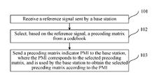
- the method is executed by user equipment (UE), and as shown in FIG. 1 , the method includes:
- Step 101 Receive a reference signal sent by a base station.
- the reference signal sent by the base station may include a channel state information reference signal (CSI RS), or a demodulation reference signal (DM RS), or a cell-specific reference signal (CRS).
- the user equipment UE may obtain a resource configuration of the reference signal by receiving a notification of the eNB such as RRC (radio resource control) signaling or DCI (downlink control information), or on the basis of a cell identity (ID); and obtain the reference signal in a corresponding resource or subframe.
- CSI RS channel state information reference signal
- DM RS demodulation reference signal
- CRS cell-specific reference signal
- the user equipment UE may obtain a resource configuration of the reference signal by receiving a notification of the eNB such as RRC (radio resource control) signaling or DCI (downlink control information), or on the basis of a cell identity (ID); and obtain the reference signal in a corresponding resource or subframe.
- RRC radio resource control
- DCI downlink control information
- W 1 Z diag ⁇ X 1 Z 1 , . . . ,X N B Z N B ⁇ (4)
- [ ] T represents matrix transposition
- e i,k represents an n i x1 selection vector, where in the vector, the k th element is 1 and all other elements are 0, and n i is a half of a column quantity of a block matrix X i , that is, 2n i is a column quantity of the block matrix x i ;
- ⁇ i,k is a phase shift, ⁇ i,k ⁇ 0, ⁇ i,k ⁇ 0; and
- X i corresponds to Z i .
- two column vectors (or referred to as beams) can be separately selected from each block matrix x i by using two e i,k and z i,k ; phase alignment and weighting are performed on the two column vectors (or beams) by using ⁇ i,k and ⁇ i,k e j ⁇ i,k , where the two column vectors selected from X i may separately point to two major multipath transmission directions.
- the block diagonal matrix W 1 is a beam group formed by the block matrices X i that include different beams (or column vectors), and correspondingly, each column of each block matrix Z i included in the matrix Z is used to combine (including phase alignment and weighting) two beams in the block matrix X i , where directions of the two beams may separately point to two major multipath transmission directions. Therefore, for each column of an obtained matrix X i Z i interference between two major multipath transmission directions can be converted into a wanted signal by using the foregoing structure, thereby significantly improving transmit power corresponding to each column of X i Z i .
- the parameters ⁇ i,k and ⁇ i,k may be equal, and in this case, equal-power combining gains of two beams are obtained.
- One of the parameters ⁇ i,k and ⁇ i,k may be 0, and in this case, selective combining gains of two beams are obtained.
- the parameters ⁇ i,k and ⁇ i,k may also be other quantized values, for example, a value of ⁇ i,k e j ⁇ i,k may be selected from a constellation diagram of modulation such as 16QAM or 64QAM, and in this case, maximum ratio combining gains of two beams are obtained.
- the matrix W 2 is used to select one or more column vectors in the matrix W 1 Z and perform weighting combination to form the matrix W.
- the precoding matrix W can further adapt to a sub-band or a short-term characteristic of a channel, and one-layer or multi-layer transmission is formed, thereby improving a transmission rate.
- each column of the matrix x i,j may be selected from columns of a Householder (Householder) matrix H, where the matrix H is: H ⁇ I ⁇ 2 u n u n H /u n H u n ⁇ (7)
- the vector u n may be a vector used in an LTE R8 4-antenna codebook, and is shown in the following table:
- Each column of the matrix x i,j in formula (6) may also be selected from columns of a discrete Fourier transform (DFT) matrix F, where the matrix F is:
- N ⁇ N represents that an element in the (m+1) th row and the (n+1) th column is an N ⁇ N matrix of
- Multiple different DFT matrices may be obtained by selecting G and g.
- Each column of the matrix x i,j in formula (6) may also be selected from columns of the following Hadamard (Hadamard) matrix or rotated Hadamard matrix: diag ⁇ 1, e jm ⁇ /N ,e jm ⁇ /N ,e j3m/N ⁇ H n (9)
- H n is an n-order Hadamard matrix
- H n is an n-order Hadamard matrix
- H 4 is:
- H 4 [ 1 1 1 1 1 1 - 1 1 - 1 1 - 1 - 1 1 - 1 - 1 1 ] ( 10 )
- Each column of the matrix x i,j in formula (6) may also be selected from columns of a precoding matrix in an LTE R8 system 2-antenna or 4-antenna codebook or in an LTE R10 system 8-antenna codebook.
- each column of the matrix A i,j or the matrix B i,j in formula (11) may be a column vector of the Householder matrix shown in (7), or the DFT matrix shown in (8), or the Hadamard matrix or the rotated Hadamard matrix shown in (9) or (10), or the precoding matrix in the LTE R8 system 2-antenna or 4-antenna codebook or in the LTE R10 system 8-antenna codebook.
- other forms may also be used for the matrix A i,j or the matrix B i,j , which are not described in detail herein.
- the precoding matrix w can adapt to an antenna configuration of the AAS base station, thereby fully using freedom in horizontal and perpendicular directions of an antenna of the AAS base station.
- block matrices X i in formula (6) may be equal to each other, where 1 ⁇ i ⁇ N B ; in this way, relevance between channels can be fully used, and feedback overheads can be further reduced.
- the structure shown in (5) helps select two antenna ports by directly using two e i,k in z i,k , and helps perform phase alignment and weighting on the two antenna ports by using ⁇ i,k e j ⁇ i,k , where the two selected antenna ports may separately align with two major multipath transmission directions.
- An actually deployed antenna port may correspond to a virtual antenna, where each virtual antenna is obtained by performing weighting combination on multiple physical antennas, and virtual antennas may have different beam directions; therefore, in the foregoing precoding structure, different beam directions of the antenna ports can be fully used, and interference between two major multipath transmission directions can be directly converted into a wanted signal, thereby significantly improving a system transmission rate.
- phase ⁇ i,k in the structure (5) may be selected from the following values:
- N is a positive integer, for example, N is 2 to the power of n, where n is a positive integer.
- the foregoing block matrices Z i may be equal to each other, where 1 ⁇ i ⁇ N B ; in this way, relevance between channels can be fully used, and feedback overheads can be further reduced.
- the matrix W 2 is used to select or perform weighting combination on a column vector in the matrix w 1 z to form the matrix W.
- the selecting, based on the reference signal, a precoding matrix from a codebook may include:
- a predefined rule such as a rule of maximizing a channel capacity or a throughput
- Step 103 Send a precoding matrix indicator (PMI) to the base station according to the selected precoding matrix w, where the PMI is used by the base station to obtain the selected precoding matrix w according to the PMI.
- PMI precoding matrix indicator
- the precoding matrix w is included in a precoding matrix set or a codebook, and the PMI is used to indicate the precoding matrix w selected from the precoding matrix set or the codebook.
- the sending a precoding matrix indicator PMI to the base station includes: sending the precoding matrix indicator PMI to the base station, where the PMI may only include a specific value, and in this case, the PMI directly indicates the precoding matrix w.
- the PMI may only include a specific value, and in this case, the PMI directly indicates the precoding matrix w.
- the PMI may only include a specific value, and in this case, the PMI directly indicates the precoding matrix w.
- PMI may only include a specific value, and in this case, the PMI directly indicates the precoding matrix w.
- the sending a precoding matrix indicator PMI to the base station may also include: sending precoding matrix indicators PMI 1 and PMI 2 to the base station, where the PMI 1 and the PMI 2 are respectively used to indicate the matrix w 1 z and the matrix W 2 in formula (1), and in this case, the matrix w 1 z and the matrix W 2 are respectively indicated by the PMI 1 and the PMI 2 in the codebook;
- the sending a precoding matrix indicator PMI to the base station may also include: sending a third precoding matrix indicator PMI 3 and a fourth precoding matrix indicator PMI 4 to the base station, where the PMI 3 is used to indicate the matrix W 1 , and the PMI 4 is used to indicate the matrix zw 2 ;
- the precoding matrix indicators PMI 1 and PMI 2 , or PMI 3 and PMI 4 , or PMI 2 , PMI 3 , and PMI 5 have different time domains or frequency domain granularities.
- the sending a precoding matrix indicator PMI to the base station specifically includes:
- the PMI 5 to the base station according to a fifth frequency domain granularity, where the third frequency domain granularity is less than the second frequency domain granularity and the fifth frequency domain granularity, for example, sending a wideband PMI 2 , a wideband PMI 5 , and a sub-band PMI 3 to the base station.
- the sizes of the foregoing wideband and sub-band may vary with the size of a system bandwidth.
- the wideband in a 10 MHz LTE system that includes 50 physical resource blocks (RBs), the wideband may include 50 RBs, and the size of the sub-band may be 6 consecutive RBs; and in a 5 MHz LTE system, the wideband may include 25 RBs, and the size of the sub-band may be 3 consecutive RBs.
- feedback overheads can be further reduced by using time or frequency domain relevance between channels.
- the sending a precoding matrix indicator (PMI) to the base station may also include: sending a precoding matrix indicator PMI1 i , where 1 ⁇ i ⁇ N B , and the PMI 2 to the base station; PMI1 i , where 1 ⁇ i ⁇ N B , and the PMI 2 are respectively used to indicate the matrix x i z i , where 1 ⁇ i ⁇ N B , and the matrix W 2 ;
- PMI3 i where 1 ⁇ i ⁇ N B , and the PMI 4 to the base station
- PMI3 i where 1 ⁇ i ⁇ N B , is used to indicate X i
- the PMI 4 is used to indicate the matrix zw 2 ;
- the sending a precoding matrix indicator (PMI) to the base station may be: sending, by the UE, the precoding matrix indicator PMI to the base station through a physical uplink control channel (PUCCH) or a physical uplink shared channel (PUCCH).
- a precoding matrix indicator PMI
- PUCCH physical uplink control channel
- PUCCH physical uplink shared channel
- the sending a precoding matrix indicator (PMI) to the base station may be: separately sending, by the UE to the base station by using different subframes or in different periods, the PMI 1 and the PMI 2 , or the PMI 3 and the PMI 4 , or the PMI 2 , the PMI 3 , and the PMI 3 , or the PMI1 i , where 1 ⁇ i ⁇ N B , and the PMI 2 , or the PMI3, i and the PMI 4 , or the PMI3 i , where 1 ⁇ i ⁇ N B , the PMI 2 , and the PMI 5 , or the PMI5 i , where 1 ⁇ i ⁇ N B /2, and the PMI 2 .
- the sending a precoding matrix indicator (PMI) to the base station may also be: separately sending, by the UE to the base station according to different sub-bands or sub-band widths in a frequency domain, the PMI 1 and the PMI 2 , or the PMI 3 and the PMI 4 , or the PMI 2 , the PMI 3 , and the PMI 5 , or the PMI1 i , where 1 ⁇ i ⁇ N B , and the PMI 2 , or the PMI3, i and the PMI 4 , or the PMI3 i , where 1 ⁇ i ⁇ N B , the PMI 2 , and the PMI 5 , or the PMI5 i , where 1 ⁇ i ⁇ N B /2, and the PMI 2 .
- multiple block matrices X i may separately correspond to antenna groups of different polarizations or different locations; therefore, the precoding matrix can match multiple antenna deployments or configurations.
- the foregoing codebook structure can significantly improve performance of MIMO, especially MU-MIMO.
- one or more PMIs are fed back based on a subset, to indicate the precoding matrix; therefore, time/frequency domain/space relevance between channels is fully used, thereby significantly reducing feedback overheads.
- the selecting, based on the reference signal, a precoding matrix from a codebook is specifically:
- the codebook subset may be a predefined codebook subset; or may be a codebook subset as follows: the codebook subset is reported by the UE to the base station eNB, notified by the base station eNB based on a report of the UE, and then told by the base station to the UE; or may be a codebook subset that is determined and reported by the UE, for example, a recently reported codebook subset.
- codebook subset and another codebook subset share at least one same matrix subset of the following matrix subsets: subsets of a matrix W 1 , a matrix w 1 z, a matrix W 2 , a matrix zw 2 , and a matrix Z.
- the precoding matrix is selected based on the codebook subset, which can further reduce feedback overheads and implementation complexity.
- the codebook subsets share a same subset of the matrix W 1 , or the matrix w 1 z, or the matrix W 2 , or the matrix zw 2 , or the matrix Z, and therefore, the codebook subsets overlap with each other, which can overcome an edge effect of quantization of channel state information.
- the block matrices X i of the block diagonal matrix W 1 may be unequal, or may be equal. If the block diagonal matrix W 1 has multiple equal block matrices, for example, equal block matrices may appear in pairs, feedback overheads can be further reduced.
- the three matrices W 1 , Z, and W 2 included in the precoding matrix W that is selected, based on the reference signal, from the codebook may further be multiplied by a scale factor, so as to implement power normalization or power balancing.
- the codebook may further include other precoding matrices, so as to meet requirements of other scenarios, which is not limited herein.
- This embodiment of the present invention provides the method for reporting channel state information.
- [ ] T represents matrix transposition
- e i,k represents an n i x1 selection vector, where in the vector, the k th element is 1 and all other elements are 0, and n i is a half of a column quantity of a block matrix x i
- ⁇ i,k is a phase shift, ⁇ i,k ⁇ 0, and ⁇ i,k ⁇ 0
- PMI precoding matrix indicator
- two column vectors (or referred to as beams) can be separately selected from each block matrix X i by using the structure of the matrix Z; and phase alignment and weighting are performed on the two column vectors (or beams), where the two column vectors selected from X i may separately point to two major multipath transmission directions. Therefore, by using the foregoing structure, for each column of an obtained matrix x i z i , interference between two major multipath transmission directions can be converted into a wanted signal, and combining gains are obtained, thereby improving system transmission reliability and a system transmission throughput.
- This embodiment of the present invention further provides a method for reporting channel state information.
- the method is executed by a base station, and as shown in FIG. 3 , the method includes:
- [ ] T represents matrix transposition
- e i,k represents an n i x1 selection vector, where in the vector, the k th element is 1 and all other elements are 0, and n i is a half of a column quantity of a block matrix x i
- ⁇ i,k is a phase shift, ⁇ i,k ⁇ 0, ⁇ i,k ⁇ 0
- X i corresponds to Z i .
- the codebook may further include other precoding matrices, so as to meet requirements of other scenarios, which is not limited herein.
- PMI precoding matrix indicator
- two column vectors (or referred to as beams) can be separately selected from each block matrix X i by using the structure of the matrix Z; and phase alignment and weighting are performed on the two column vectors (or beams), where the two column vectors selected from X i may separately point to two major multipath transmission directions. Therefore, by using the foregoing structure, for each column of an obtained matrix x i z i , interference between two major multipath transmission directions can be converted into a wanted signal, and combining gains are obtained, thereby improving system transmission reliability and a system transmission throughput.
- the following describes in detail interaction between devices for implementing a method for reporting channel state information provided in this embodiment of the present invention, and as shown in FIG. 4 , the method includes:
- Abase station sends a reference signal to user equipment UE.
- the user equipment receives the reference signal sent by the base station.
- [ ] T represents matrix transposition
- e i,k represents an n i x1 selection vector, where in the vector, the k th element is 1 and all other elements are 0, and n i is a half of a column quantity of a block matrix x i
- ⁇ i,k is a phase shift, ⁇ i, k ⁇ 0, ⁇ i,k ⁇ 0
- X i corresponds to z i .
- the user equipment sends a precoding matrix indicator (PMI) to the base station, where the PMI corresponds to the selected precoding matrix, and is used by the base station to obtain the selected precoding matrix w according to the PMI.
- PMI precoding matrix indicator
- the base station receives the precoding matrix indicator (PMI) sent by the UE.
- PMI precoding matrix indicator
- PMI precoding matrix indicator
- two column vectors (or referred to as beams) can be separately selected from each block matrix X i by using the foregoing structure; and phase alignment and weighting are performed on the two column vectors (or beams), where the two column vectors selected from X i may separately point to two major multipath transmission directions. Therefore, by using the foregoing structure, for each column of an obtained matrix x i z i , interference between two major multipath transmission directions can be converted into a wanted signal, and combining gains are obtained, thereby improving system transmission reliability and a system transmission throughput.
- the user equipment includes: a receiving unit 51 , a selection unit 52 , and a sending unit 53 .
- the receiving unit 51 is configured to receive a reference signal sent by a base station.
- [ ] T represents matrix transposition
- e i,k represents an n i x1 selection vector, where in the vector, the k th element is 1 and all other elements are 0, and n i is a half of a column quantity of a block matrix X i
- ⁇ i,k is a phase shift, ⁇ i,k ⁇ 0, ⁇ i,k ⁇ 0
- X i corresponds to Z i .
- the sending unit 53 is configured to send a precoding matrix indicator (PMI) to the base station, where the PMI corresponds to the selected precoding matrix, and is used by the base station to obtain the selected precoding matrix w according to the PMI.
- PMI precoding matrix indicator
- the selection unit 52 is specifically configured to select, based on the reference signal, the precoding matrix from a codebook subset, where the codebook subset is a subset predefined, or notified by the base station, or reported by the user equipment.
- the codebook subsets share at least one same matrix subset of the following matrix subsets: subsets of a matrix W 1 , a matrix w 1 z, a matrix W 2 , a matrix zw 2 , and a matrix Z.
- the sending unit 53 may be specifically configured to send a first precoding matrix indicator PMI 1 and a second precoding matrix indicator PMI 2 to the base station, where the PMI 1 is used to indicate the matrix w 1 z, and the PMI 2 is used to indicate the matrix W 2 ; or
- the sending unit 53 may be specifically configured to send the PMI 1 to the base station according to a first period
- the sending unit 53 may further be specifically configured to send the PMI 1 to the base station according to a first frequency domain granularity
- the PMI 2 to the base station according to a second frequency domain granularity, where the first frequency domain granularity is greater than the second frequency domain granularity, for example, send a wideband PMI i and a sub-band PMI 2 to the base station; or
- the PMI 4 to the base station according to a fourth frequency domain granularity, where the third frequency domain granularity is greater than the fourth frequency domain granularity, for example, send a wideband PMI 3 and a sub-band PMI 4 to the base station; or
- the PMI 5 to the base station according to a fifth frequency domain granularity, where the third frequency domain granularity is less than the second frequency domain granularity and the fifth frequency domain granularity, for example, send a wideband PMI 2 , a wideband PMI 5 , and a sub-band PMI 3 to the base station.
- the sizes of the foregoing wideband and sub-band may vary with the size of a system bandwidth.
- the wideband may include 50 physical resource blocks RBs, and the size of the sub-band may be 6 consecutive RBs; and in a 5 MHz LTE system, the wideband may include 25 RBs, and the size of the sub-band may be 3 consecutive RBs.
- the block matrix X i [X i,1 X i,2 ], where each column of the matrix x i,j is selected from columns of a Householder matrix, a discrete Fourier transform matrix, a Hadamard matrix, a rotated Hadamard matrix, or a precoding matrix in an LTE R8 system 2-antenna or 4-antenna codebook or in an LTE R10 system 8-antenna codebook.
- columns of the matrix X i,1 and the matrix x i,2 are column vectors of a Householder matrix, a discrete Fourier transform matrix, a Hadamard matrix, a rotated Hadamard matrix, or a precoding matrix in an LTE R8 system 2-antenna or 4-antenna codebook or in an LTE R10 system 8-antenna codebook.
- w 1 is an identity matrix
- the user equipment includes: a transceiver 601 , a memory 602 , and a processor 603 .
- the user equipment may further include common-purpose components such as an antenna and an input/output apparatus, which is not limited herein in this embodiment of the present invention.
- the memory 602 stores a set of program code
- [ ] T represents matrix transposition
- e i,k represents an n i x1 selection vector, where in the vector, the k th element is 1 and all other elements are 0, and n i is a half of a column quantity of a block matrix x i
- ⁇ i,k is a phase shift, ⁇ i,k ⁇ 0, ⁇ i,k ⁇ 0
- X i corresponds to Z i ; and sending a precoding matrix indicator (PMI) to the base station by using the transceiver 601 , where the PMI corresponds to the selected precoding matrix, and is used by the base station to obtain the selected precoding matrix w according to the PMI.
- PMI precoding matrix indicator
- the selecting, based on the reference signal, a precoding matrix from a codebook specifically includes:
- the precoding matrix selecting, based on the reference signal, the precoding matrix from a codebook subset, where the codebook subset is a subset predefined, or notified by the base station, or reported by the user equipment.
- the codebook subsets share at least one same matrix subset of the following matrix subsets: subsets of a matrix W 1 , a matrix w 1 z, a matrix W 2 , a matrix zw 2 , and a matrix Z.
- the sending a precoding matrix indicator (PMI) to the base station by using the transceiver 601 specifically includes:
- the sending a precoding matrix indicator PMI to the base station by using the transceiver 601 specifically includes:
- the sending a precoding matrix indicator (PMI) to the base station by using the transceiver 601 specifically includes:
- the PMI 5 to the base station according to a fifth frequency domain granularity, where the third frequency domain granularity is less than the second frequency domain granularity and the fifth frequency domain granularity, for example, sending a wideband PMI 2 , a wideband PMI 5 , and a sub-band PMI 3 to the base station.
- the sizes of the foregoing wideband and sub-band may vary with the size of a system bandwidth.
- the wideband may include 50 physical resource blocks RBs, and the size of the sub-band may be 6 consecutive RBs; and in a 5 MHz LTE system, the wideband may include 25 RBs, and the size of the sub-band may be 3 consecutive RBs.
- the block matrix X i [X i,1 X i,2 ], where each column of the matrix x i,j is selected from columns of a Householder matrix, a discrete Fourier transform matrix, a Hadamard matrix, a rotated Hadamard matrix, or a precoding matrix in an LTE R8 system 2-antenna or 4-antenna codebook or in an LTE R10 system 8-antenna codebook.
- columns of the matrix X i,1 and the matrix x i,2 are column vectors of a Householder matrix, a discrete Fourier transform matrix, a Hadamard matrix, a rotated Hadamard matrix, or a precoding matrix in an LTE R8 system 2-antenna or 4-antenna codebook or in an LTE R10 system 8-antenna codebook.
- w 1 is an identity matrix
- the codebook may further include other precoding matrices, so as to meet requirements of other scenarios, which is not limited herein.
- PMI precoding matrix indicator
- two column vectors (or referred to as beams) can be separately selected from each block matrix x i by using the foregoing structure; and phase alignment and weighting are performed on the two column vectors (or beams), where the two column vectors selected from x i may separately point to two major multipath transmission directions. Therefore, by using the foregoing structure, for each column of an obtained matrix x i z i , interference between two major multipath transmission directions can be converted into a wanted signal, and combining gains are obtained, thereby improving system transmission reliability and a system transmission throughput.
- the base station includes: a sending unit 71 , a receiving unit 72 , and a determining unit 73 .
- the sending unit 71 is configured to send a reference signal to user equipment UE.
- the receiving unit 72 is configured to receive a precoding matrix indicator (PMI) sent by the UE.
- PMI precoding matrix indicator
- [ ] T represents matrix transposition
- e i,k represents an n i x1 selection vector, where in the vector, the k th element is 1 and all other elements are 0, and n i is a half of a column quantity of a block matrix X i
- ⁇ i,k is a phase shift, ⁇ i,k ⁇ 0, ⁇ i,k ⁇ 0
- X i corresponds to z i .
- the determining unit 73 is specifically configured to determine the precoding matrix in a codebook subset according to the PMI, where the codebook subset is a subset predefined, or reported by the user equipment, or notified by the base station.
- the codebook subsets share at least one same matrix subset of the following matrix subsets: subsets of a matrix W 1 , a matrix w 1 z, a matrix W 2 , a matrix zw 2 , and a matrix Z.
- the receiving unit 72 is specifically configured to:
- the UE receives a first precoding matrix indicator PMI 1 and a second precoding matrix indicator PMI 2 that are sent by the UE, where the PMI 1 is used to indicate the matrix w 1 z, and the PMI 2 is used to indicate the matrix W 2 ;
- a second precoding matrix indicator PMI 2 receives a second precoding matrix indicator PMI 2 , a third precoding matrix indicator PMI 3 , and a fifth precoding matrix indicator PMI 5 that are sent by the UE, where the PMI5 is used to indicate the matrix z.
- the receiving unit 72 is specifically configured to:
- the receiving unit 72 is specifically configured to:
- the PMI 2 sent by the UE, where the first frequency domain granularity is greater than the second frequency domain granularity, for example, a wideband PMI 1 and a sub-band PMI 2 are sent to the base station; or
- the PMI 4 sent by the UE receives, according to a fourth frequency domain granularity, the PMI 4 sent by the UE, where the third frequency domain granularity is greater than the fourth frequency domain granularity, for example, a wideband PMI 3 and a sub-band PMI 4 are sent to the base station; or
- the PMI 5 sent by the UE, where the third frequency domain granularity is less than the second frequency domain granularity and the fifth frequency domain granularity, for example, a wideband PMI 2 , a wideband PMI 5 , and a sub-band PMI 3 are sent to the base station.
- the sizes of the foregoing wideband and sub-band may vary with the size of a system bandwidth.
- the wideband may include 50 physical resource blocks RBs, and the size of the sub-band may be 6 consecutive RBs; and in a 5 MHz LTE system, the wideband may include 25 RBs, and the size of the sub-band may be 3 consecutive RBs.
- the block matrix X i [X i,1 X i,2 ], where each column of the matrix x i,j is selected from columns of a Householder matrix, a discrete Fourier transform matrix, a Hadamard matrix, a rotated Hadamard matrix, or a precoding matrix in an LTE R8 system 2-antenna or 4-antenna codebook or in an LTE R10 system 8-antenna codebook.
- each column of the matrix x i,j is separately selected from columns of different Householder matrices, different discrete Fourier transform matrices, different Hadamard matrices, different rotated Hadamard matrices, or different precoding matrices in an LTE R8 system 2-antenna or 4-antenna codebook or in an LTE R10 system 8-antenna codebook.
- columns of the matrix X i,1 and the matrix x i,2 are column vectors of a Householder matrix, a discrete Fourier transform matrix, a Hadamard matrix, a rotated Hadamard matrix, or a precoding matrix in an LTE R8 system 2-antenna or 4-antenna codebook or in an LTE R10 system 8-antenna codebook.
- W 1 is an identity matrix.
- the base station includes: a transceiver 801 , a memory 802 , and a processor 803 .
- the base station may further include common-purpose components such as an antenna and an input/output apparatus, which is not limited herein in this embodiment of the present invention.
- the memory 802 stores a set of program code
- the processor 803 is configured to invoke the program code stored in the memory 802 , to perform the following operations:
- [ ] T represents matrix transposition
- e i,k represents an n i x1 selection vector, where in the vector, the k th element is 1 and all other elements are 0, and n i is a half of a column quantity of a block matrix x i
- ⁇ i,k is a phase shift, ⁇ i,k ⁇ 0, ⁇ i,k ⁇ 0
- x i corresponds to z i .
- the determining a precoding matrix w in a codebook according to the PMI specifically includes: determining the precoding matrix in a codebook subset according to the PMI, where the codebook subset is a subset predefined, or reported by the user equipment, or notified by the base station.
- the codebook subsets share at least one same matrix subset of the following matrix subsets: subsets of a matrix W 1 , a matrix w 1 z, a matrix W 2 , a matrix ZW 2 , and a matrix Z.
- the receiving the PMI by using the transceiver 801 may specifically include: receiving a first precoding matrix indicator PMI 1 and a second precoding matrix indicator PMI 2 that are sent by the UE, where the PMI 1 is used to indicate the matrix w 1 z, and the PMI 2 is used to indicate the matrix W 2 ;
- the receiving the PMI by using the transceiver 801 may specifically include: receiving, according to a first period, the PMI 1 sent by the UE; and
- the receiving the PMI by using the transceiver 801 may further specifically include: receiving, according to a first frequency domain granularity, the PMI 1 sent by the UE; and
- the PMI 2 sent by the UE receives, according to a second frequency domain granularity, the PMI 2 sent by the UE, where the first frequency domain granularity is greater than the second frequency domain granularity, for example, receiving a wideband PMI 1 and a sub-band PMI 2 that are sent by the UE; or
- the PMI 4 sent by the UE receives, according to a fourth frequency domain granularity, the PMI 4 sent by the UE, where the third frequency domain granularity is greater than the fourth frequency domain granularity, for example, receiving a wideband PMI 3 and a sub-band PMI 4 that are sent by the UE; or
- the PMI 5 sent by the UE receives, according to a fifth frequency domain granularity, the PMI 5 sent by the UE, where the third frequency domain granularity is less than the second frequency domain granularity and the fifth frequency domain granularity, for example, receiving a wideband PMI 2 , a wideband PMI 5 , and a sub-band PMI 3 that are sent by the UE.
- the sizes of the foregoing wideband and sub-band may vary with the size of a system bandwidth.
- the wideband may include 50 physical resource blocks RBs, and the size of the sub-band may be 6 consecutive RBs; and in a 5 MHz LTE system, the wideband may include 25 RBs, and the size of the sub-band may be 3 consecutive RBs.
- the block matrix X i [X i,1 X i,2 ], where each column of the matrix x i,j is selected from columns of a Householder matrix, a discrete Fourier transform matrix, a Hadamard matrix, a rotated Hadamard matrix, or a precoding matrix in an LTE R8 system 2-antenna or 4-antenna codebook or in an LTE R10 system 8-antenna codebook.
- each column of the matrix x i,j is separately selected from columns of different Householder matrices, different discrete Fourier transform matrices, different Hadamard matrices, different rotated Hadamard matrices, or different precoding matrices in an LTE R8 system 2-antenna or 4-antenna codebook or in an LTE R10 system 8-antenna codebook.
- columns of the matrix X i,1 and the matrix x i,2 are column vectors of a Householder matrix, a discrete Fourier transform matrix, a Hadamard matrix, a rotated Hadamard matrix, or a precoding matrix in an LTE R8 system 2-antenna or 4-antenna codebook or in an LTE R10 system 8-antenna codebook.
- W 1 is an identity matrix.
- the codebook may further include other precoding matrices, so as to meet requirements of other scenarios, which is not limited herein.
- PMI precoding matrix indicator
- two column vectors (or referred to as beams) can be separately selected from each block matrix X i by using the foregoing structure; and phase alignment and weighting are performed on the two column vectors (or beams), where the two column vectors selected from X i may separately point to two major multipath transmission directions. Therefore, by using the foregoing structure, for each column of an obtained matrix x i z i , interference between two major multipath transmission directions can be converted into a wanted signal, and combining gains are obtained, thereby improving system transmission reliability and a system transmission throughput.
- the disclosed system, apparatus, and method may be implemented in other manners.
- the described apparatus embodiment is merely exemplary.
- the module or unit division is merely logical function division and may be other division in actual implementation.
- a plurality of units or components may be combined or integrated into another system, or some features may be ignored or not performed.
- the displayed or discussed mutual couplings or direct couplings or communication connections may be implemented through some interfaces.
- the indirect couplings or communication connections between the apparatuses or units may be implemented in electronic, mechanical, or other forms.
- the units described as separate parts may or may not be physically separate, and parts displayed as units may or may not be physical units, may be located in one position, or may be distributed on a plurality of network units. Some or all of the units may be selected according to actual needs to achieve the objectives of the solutions of the embodiments.
- functional units in the embodiments of the present invention may be integrated into one processing unit, or each of the units may exist alone physically, or two or more units are integrated into one unit.
- the integrated unit may be implemented in a form of hardware, or may be implemented in a form of a software functional unit.
- the integrated unit When the integrated unit is implemented in the form of a software functional unit and sold or used as an independent product, the integrated unit may be stored in a computer-readable storage medium.
- the software product is stored in a storage medium and includes several instructions for instructing a computer device (which may be a personal computer, a server, or a network device) or a processor to perform all or some of the steps of the methods described in the embodiments of the present invention.
- the foregoing storage medium includes: any medium that can store program code, such as a USB flash drive, a removable hard disk, a read-only memory (ROM), a random access memory (RAM), a magnetic disk, or an optical disc.
Abstract
Description
y=HVs+n
z i,k=(αi,k 2+βi,k 2)−1/2[αi,k e i,k Tβi,k e jθ
z i,k=(αi,k 2+βi,k 2)−1/2[αi,k e i,k Tβi,k e jθ
z i,k=(αi,k 2+βi,k 2)−1/2[αi,k e i,k Tβi,k e jθ
z i,k=(αi,k 2+βi,k 2)−1/2[αi,k e i,k Tβi,k e jθ
z i,k=(αi,k 2+βi,k 2)−1/2[αi,k e i,k Tβi,k e jθ
w=w 1 zw 2 (1)
W 1=diag{X 1 , . . . ,X N
Z=diag{Z 1 , . . . ,Z N
W 1 Z=diag{X 1 Z 1 , . . . ,X N
z i,k=(αi,k 2+βi,k 2)−1/2[αi,k e i,k Tβi,k e jθ
X i=[X i,1 X i,2],1≤i≤N B (6)
H∈{I−2u n u n H /u n H u n} (7)
| u0 = [1 −1 −1 −1]T | ||
| u1 = [1 −j 1 j]T | ||
| u2 = [1 1 −1 1]T | ||
| u3 = [1 j 1 −j]T | ||
| u4 = [1 (−1 − j)/{square root over (2)} −j (1 − j)/{square root over (2)}]T | ||
| u5 = [1 (1 − j)/{square root over (2)} j (−1 − j)/{square root over (2)}]T | ||
| u6 = [1 (1 + j)/{square root over (2)} −j (−1 + j)/{square root over (2)}]T | ||
| u7 = [1 (−1 + j)/{square root over (2)} j (1 + j)/{square root over (2)}]T | ||
| u8 = [1 −1 1 1]T | ||
| u9 = [1 −j −1 −j]T | ||
| u10 = [1 1 1 −1]T | ||
| u11 = [1 j −1 j]T | ||
| u12 = [1 −1 −1 1]T | ||
| u13 = [1 −1 1 −1]T | ||
| u14 = [1 1 −1 −1]T | ||
| u15 = [1 1 1 1]T | ||
represents that an element in the (m+1)th row and the (n+1)th column is an N×N matrix of
where
diag{1,e jmπ/N ,e jmπ/N ,e j3m/N }H n (9)
x i,j =A i,j ⊗B i,j,1≤i≤N B ,j=1,2 (11)
z i,k=(αi,k 2+βi,k 2)−1/2[αi,k e i,k Tβi,k e jθ
z i,k=(αi,k 2+βi,k 2)−1/2[αi,k e i,k Tβi,k e jθ
z i,k=(αi,k 2+βi,k 2)−1/2[αi,k e i,k Tβi,k e jθ
z i,k=(αi,k 2+βi,k 2)−1/2[αi,k e i,k Tβi,k e jθ
z i,k=(αi,k 2+βi,k 2)−1/2[αi,k e i,k Tβi,k e jθ
z i,k=(αi,k 2+βi,k 2)−1/2[αi,k e i,k Tβi,k e jθ
z i,k=(αi,k 2+βi,k 2)−1/2[αi,k e i,k Tβi,k e jθ
Claims (28)
z i,k=(αi,k 2+βi,k 2)−1/2[αi,k e i,k Tβi,k e jθ
z i,k=(αi,k 2+βi,k 2)−1/2[αi,k e i,k Tβi,k e jθ
z i,k=(αi,k 2+βi,k 2)−1/2[αi,k e i,k Tβi,k e jθ
z i,k=(αi,k 2+βi,k 2)−1/2[αi,k e i,k Tβi,k e jθ
Priority Applications (3)
| Application Number | Priority Date | Filing Date | Title |
|---|---|---|---|
| US16/058,636 US10447356B2 (en) | 2013-04-15 | 2018-08-08 | Method for reporting channel state information, user equipment, and base station |
| US16/594,646 US10735063B2 (en) | 2013-04-15 | 2019-10-07 | Method for reporting channel state information, user equipment, and base station |
| US16/937,561 US11184062B2 (en) | 2013-04-15 | 2020-07-23 | Method for reporting channel state information, user equipment, and base station |
Applications Claiming Priority (5)
| Application Number | Priority Date | Filing Date | Title |
|---|---|---|---|
| PCT/CN2013/074214 WO2014169421A1 (en) | 2013-04-15 | 2013-04-15 | Method for reporting channel state information, user device, and base station |
| US14/883,334 US9608708B2 (en) | 2013-04-15 | 2015-10-14 | Method for reporting channel state information, user equipment, and base station |
| US15/439,686 US9838097B2 (en) | 2013-04-15 | 2017-02-22 | Method for reporting channel state information, user equipment, and base station |
| US15/808,318 US10063296B2 (en) | 2013-04-15 | 2017-11-09 | Method for reporting channel state information, user equipment, and base station |
| US16/058,636 US10447356B2 (en) | 2013-04-15 | 2018-08-08 | Method for reporting channel state information, user equipment, and base station |
Related Parent Applications (1)
| Application Number | Title | Priority Date | Filing Date |
|---|---|---|---|
| US15/808,318 Continuation US10063296B2 (en) | 2013-04-15 | 2017-11-09 | Method for reporting channel state information, user equipment, and base station |
Related Child Applications (1)
| Application Number | Title | Priority Date | Filing Date |
|---|---|---|---|
| US16/594,646 Continuation US10735063B2 (en) | 2013-04-15 | 2019-10-07 | Method for reporting channel state information, user equipment, and base station |
Publications (2)
| Publication Number | Publication Date |
|---|---|
| US20180351616A1 US20180351616A1 (en) | 2018-12-06 |
| US10447356B2 true US10447356B2 (en) | 2019-10-15 |
Family
ID=51730659
Family Applications (6)
| Application Number | Title | Priority Date | Filing Date |
|---|---|---|---|
| US14/883,334 Active US9608708B2 (en) | 2013-04-15 | 2015-10-14 | Method for reporting channel state information, user equipment, and base station |
| US15/439,686 Active US9838097B2 (en) | 2013-04-15 | 2017-02-22 | Method for reporting channel state information, user equipment, and base station |
| US15/808,318 Active US10063296B2 (en) | 2013-04-15 | 2017-11-09 | Method for reporting channel state information, user equipment, and base station |
| US16/058,636 Active US10447356B2 (en) | 2013-04-15 | 2018-08-08 | Method for reporting channel state information, user equipment, and base station |
| US16/594,646 Active US10735063B2 (en) | 2013-04-15 | 2019-10-07 | Method for reporting channel state information, user equipment, and base station |
| US16/937,561 Active US11184062B2 (en) | 2013-04-15 | 2020-07-23 | Method for reporting channel state information, user equipment, and base station |
Family Applications Before (3)
| Application Number | Title | Priority Date | Filing Date |
|---|---|---|---|
| US14/883,334 Active US9608708B2 (en) | 2013-04-15 | 2015-10-14 | Method for reporting channel state information, user equipment, and base station |
| US15/439,686 Active US9838097B2 (en) | 2013-04-15 | 2017-02-22 | Method for reporting channel state information, user equipment, and base station |
| US15/808,318 Active US10063296B2 (en) | 2013-04-15 | 2017-11-09 | Method for reporting channel state information, user equipment, and base station |
Family Applications After (2)
| Application Number | Title | Priority Date | Filing Date |
|---|---|---|---|
| US16/594,646 Active US10735063B2 (en) | 2013-04-15 | 2019-10-07 | Method for reporting channel state information, user equipment, and base station |
| US16/937,561 Active US11184062B2 (en) | 2013-04-15 | 2020-07-23 | Method for reporting channel state information, user equipment, and base station |
Country Status (5)
| Country | Link |
|---|---|
| US (6) | US9608708B2 (en) |
| EP (3) | EP3306827B1 (en) |
| CN (3) | CN107872261B (en) |
| PL (1) | PL3661069T3 (en) |
| WO (1) | WO2014169421A1 (en) |
Families Citing this family (26)
| Publication number | Priority date | Publication date | Assignee | Title |
|---|---|---|---|---|
| CN104065448B (en) * | 2013-03-22 | 2017-11-14 | 电信科学技术研究院 | A kind of method, system and equipment for determining pre-coding matrix |
| US9774430B2 (en) * | 2014-05-22 | 2017-09-26 | Lg Electronics Inc. | Method and apparatus for channel estimation in wireless communication system |
| US10218423B2 (en) * | 2015-01-05 | 2019-02-26 | Lg Electronics Inc. | Method for reporting channel state information using polarization characteristics of antenna in wireless communication system and device therefor |
| EP3334055A4 (en) * | 2015-08-24 | 2018-09-26 | Huawei Technologies Co., Ltd. | Precoding information sending and feedback method and apparatus |
| EP3389193A4 (en) * | 2015-12-29 | 2018-12-26 | Huawei Technologies Co., Ltd. | Method and apparatus for determining pre-coding matrix |
| CN109004964B (en) | 2016-03-31 | 2021-06-04 | 瑞典爱立信有限公司 | Method and apparatus for determining precoder parameters in a wireless communication network |
| KR102150316B1 (en) * | 2016-04-01 | 2020-09-01 | 후아웨이 테크놀러지 컴퍼니 리미티드 | Feedback method and apparatus for displaying precoding matrix |
| CN107370525B (en) | 2016-05-12 | 2021-03-30 | 华为技术有限公司 | Method, base station, terminal equipment and system for channel state information feedback |
| WO2017195183A1 (en) | 2016-05-13 | 2017-11-16 | Huawei Technologies Co., Ltd. | Precoding and channel state information acquisition for multi-stream transmissions in massive mimo systems |
| CN108337026B (en) * | 2016-11-04 | 2019-03-26 | 华为技术有限公司 | Information feedback method, user equipment and the network equipment |
| CN108288987B (en) * | 2017-01-07 | 2021-10-01 | 华为技术有限公司 | Method, terminal and base station for transmitting diversity |
| EP3567771B1 (en) * | 2017-01-25 | 2022-01-19 | Huawei Technologies Co., Ltd. | Method for transmitting channel state information, access network device, and terminal device |
| CN108631838A (en) * | 2017-03-24 | 2018-10-09 | 华为技术有限公司 | The sending method of signaling, device and system |
| CN108631999B (en) | 2017-03-25 | 2021-07-09 | 华为技术有限公司 | Method, device and system for sending signaling |
| EP3619817B1 (en) * | 2017-05-04 | 2021-09-29 | Telefonaktiebolaget LM Ericsson (PUBL) | Beamforming based on combined beams |
| WO2019095309A1 (en) * | 2017-11-17 | 2019-05-23 | 华为技术有限公司 | Channel state information feedback method, communication device, and system |
| KR20200143453A (en) | 2018-04-13 | 2020-12-23 | 베르-헬라 테르모콘트롤 게엠베하 | Automotive display device |
| CN111181705B (en) * | 2018-11-15 | 2022-07-15 | 维沃移动通信有限公司 | Uplink transmission method, indication method, terminal and network equipment |
| CN111435848B (en) * | 2019-01-11 | 2022-05-31 | 华为技术有限公司 | Method for indicating and determining precoding vector and communication device |
| US10924240B2 (en) * | 2019-03-26 | 2021-02-16 | Qualcomm Incorporated | Sounding reference signal transmission to indicate a virtual antenna port |
| CN114287139A (en) * | 2019-08-23 | 2022-04-05 | 株式会社Ntt都科摩 | Terminal and wireless communication method |
| JP2022549600A (en) | 2019-09-24 | 2022-11-28 | ベーア-ヘラー サーモコントロール ゲーエムベーハー | Display device with built-in optical proximity sensor system |
| CN114829906B (en) | 2019-10-21 | 2023-04-28 | 因美纳有限公司 | System and method for structured illumination microscopy |
| US11431395B2 (en) * | 2019-10-29 | 2022-08-30 | Nokia Technologies Oy | Mapping of windowed FD basis to a combinatorial indicator for PMI reporting and usage |
| US11876654B2 (en) * | 2020-04-22 | 2024-01-16 | Qualcomm Incorporated | Methods and apparatus for unified codebooks for orthogonal sequence transmission |
| CN113938169B (en) * | 2020-06-29 | 2023-09-22 | 华为技术有限公司 | Precoding matrix determining method and device |
Citations (9)
| Publication number | Priority date | Publication date | Assignee | Title |
|---|---|---|---|---|
| WO2008133582A2 (en) | 2007-04-30 | 2008-11-06 | Telefonaktiebolaget L M Ericsson (Publ) | Method and arrangement for adapting a multi-antenna transmission |
| WO2011126160A1 (en) | 2010-04-05 | 2011-10-13 | Pantech Co.,Ltd. | Precoding method, feedback channel information method, mobile terminal and base station in wireless communication system |
| US20110261894A1 (en) | 2009-01-07 | 2011-10-27 | Panasonic Corporation | Wireless communication apparatus, wireless communication system and wireless communication method |
| CN102412885A (en) | 2011-11-25 | 2012-04-11 | 西安电子科技大学 | Three-dimensional wave beam forming method in long term evolution (LET) |
| US20120269290A1 (en) | 2011-04-25 | 2012-10-25 | Texas Instruments Incorporated | Six transmit antenna codebook design |
| EP2555445A1 (en) | 2011-08-03 | 2013-02-06 | Alcatel Lucent | Method of operating a transmitter and transmitter |
| WO2013024350A2 (en) | 2011-08-15 | 2013-02-21 | Alcatel Lucent | Methods and apparatuses for channel measurement and feedback of multi-dimensional antenna array |
| WO2013032271A2 (en) | 2011-09-02 | 2013-03-07 | 엘지전자 주식회사 | Method and apparatus for transmitting channel state information in a wireless communication system |
| US20140341312A1 (en) | 2011-11-07 | 2014-11-20 | Lg Electronics Inc. | Method for feeding back codebook-based precoding matrix information in wireless communication system and device therefor |
Family Cites Families (4)
| Publication number | Priority date | Publication date | Assignee | Title |
|---|---|---|---|---|
| CN101826945B (en) * | 2010-04-05 | 2015-08-12 | 中兴通讯股份有限公司 | The sending method of channel information and device |
| CN101931513B (en) * | 2010-05-18 | 2016-06-15 | 中兴通讯股份有限公司 | The feedback method of channel condition information and terminal |
| CN101860420B (en) * | 2010-06-18 | 2015-08-12 | 中兴通讯股份有限公司 | A kind of channel information acquisition method and system |
| WO2013185320A1 (en) * | 2012-06-14 | 2013-12-19 | 华为技术有限公司 | Method, user equipment, and base station evolved node for determining precoding matrix indicator |
-
2013
- 2013-04-15 CN CN201711130973.7A patent/CN107872261B/en active Active
- 2013-04-15 EP EP17187683.2A patent/EP3306827B1/en active Active
- 2013-04-15 PL PL19191870T patent/PL3661069T3/en unknown
- 2013-04-15 WO PCT/CN2013/074214 patent/WO2014169421A1/en active Application Filing
- 2013-04-15 CN CN201380023172.4A patent/CN104541456B/en active Active
- 2013-04-15 EP EP19191870.5A patent/EP3661069B1/en active Active
- 2013-04-15 CN CN201711132866.8A patent/CN107888269B/en active Active
- 2013-04-15 EP EP13882430.5A patent/EP2985921B1/en active Active
-
2015
- 2015-10-14 US US14/883,334 patent/US9608708B2/en active Active
-
2017
- 2017-02-22 US US15/439,686 patent/US9838097B2/en active Active
- 2017-11-09 US US15/808,318 patent/US10063296B2/en active Active
-
2018
- 2018-08-08 US US16/058,636 patent/US10447356B2/en active Active
-
2019
- 2019-10-07 US US16/594,646 patent/US10735063B2/en active Active
-
2020
- 2020-07-23 US US16/937,561 patent/US11184062B2/en active Active
Patent Citations (13)
| Publication number | Priority date | Publication date | Assignee | Title |
|---|---|---|---|---|
| WO2008133582A2 (en) | 2007-04-30 | 2008-11-06 | Telefonaktiebolaget L M Ericsson (Publ) | Method and arrangement for adapting a multi-antenna transmission |
| US8787481B2 (en) | 2007-04-30 | 2014-07-22 | Telefonaktiebolaget L M Ericsson (Publ) | Method and arrangement for adapting a multi-antenna transmission |
| CN102273115A (en) | 2009-01-07 | 2011-12-07 | 松下电器产业株式会社 | Wireless communication apparatus, wireless communication system and wireless communication method |
| US20110261894A1 (en) | 2009-01-07 | 2011-10-27 | Panasonic Corporation | Wireless communication apparatus, wireless communication system and wireless communication method |
| US20150103939A1 (en) | 2009-01-07 | 2015-04-16 | Panasonic Intellectual Property Corporation Of America | Wireless communication apparatus, wireless communication system and wireless communication method |
| WO2011126160A1 (en) | 2010-04-05 | 2011-10-13 | Pantech Co.,Ltd. | Precoding method, feedback channel information method, mobile terminal and base station in wireless communication system |
| US20120269290A1 (en) | 2011-04-25 | 2012-10-25 | Texas Instruments Incorporated | Six transmit antenna codebook design |
| EP2555445A1 (en) | 2011-08-03 | 2013-02-06 | Alcatel Lucent | Method of operating a transmitter and transmitter |
| WO2013024350A2 (en) | 2011-08-15 | 2013-02-21 | Alcatel Lucent | Methods and apparatuses for channel measurement and feedback of multi-dimensional antenna array |
| WO2013032271A2 (en) | 2011-09-02 | 2013-03-07 | 엘지전자 주식회사 | Method and apparatus for transmitting channel state information in a wireless communication system |
| US20140227987A1 (en) | 2011-09-02 | 2014-08-14 | Lg Electronics Inc. | Method and apparatus for transmitting channel state information in a wireless communication system |
| US20140341312A1 (en) | 2011-11-07 | 2014-11-20 | Lg Electronics Inc. | Method for feeding back codebook-based precoding matrix information in wireless communication system and device therefor |
| CN102412885A (en) | 2011-11-25 | 2012-04-11 | 西安电子科技大学 | Three-dimensional wave beam forming method in long term evolution (LET) |
Non-Patent Citations (3)
| Title |
|---|
| "Considerations on CSI feedback enhancements for high-priority antenna configurations", Alcatel-Lucent Shanghai Bell, Alcatel-Lucent, 3GPP TSG-RAN WG1 #66, Aug. 22-26, 2011, 7 pages, R1-112420. |
| "Downlink MIMO Enhancements for Release-12", Samsung, 3GPP TSG RAN WG1 #71, Nov. 12-16, 2012, 5 pages, R1-124933. |
| Alcatel-Lucent et al., "Way Forward on 8Tx Codebook for Rel.10 DL MIMO", 3GPP TSG RAN WG1 62, Madrid, Spain, Aug. 23-27, 2010, 6 pages, R1-105011. |
Also Published As
| Publication number | Publication date |
|---|---|
| US20180351616A1 (en) | 2018-12-06 |
| EP3661069B1 (en) | 2021-08-18 |
| CN107872261A (en) | 2018-04-03 |
| US10735063B2 (en) | 2020-08-04 |
| CN107872261B (en) | 2023-04-11 |
| EP2985921B1 (en) | 2017-08-30 |
| EP3661069A1 (en) | 2020-06-03 |
| EP3306827B1 (en) | 2019-09-11 |
| US20200358489A1 (en) | 2020-11-12 |
| US20170163321A1 (en) | 2017-06-08 |
| US20180069609A1 (en) | 2018-03-08 |
| US10063296B2 (en) | 2018-08-28 |
| CN107888269B (en) | 2022-12-13 |
| WO2014169421A1 (en) | 2014-10-23 |
| CN104541456B (en) | 2017-11-28 |
| PL3661069T3 (en) | 2022-01-17 |
| EP2985921A1 (en) | 2016-02-17 |
| US9838097B2 (en) | 2017-12-05 |
| US20160036507A1 (en) | 2016-02-04 |
| US20200044700A1 (en) | 2020-02-06 |
| CN104541456A (en) | 2015-04-22 |
| US9608708B2 (en) | 2017-03-28 |
| US11184062B2 (en) | 2021-11-23 |
| EP2985921A4 (en) | 2016-02-24 |
| CN107888269A (en) | 2018-04-06 |
| EP3306827A1 (en) | 2018-04-11 |
Similar Documents
| Publication | Publication Date | Title |
|---|---|---|
| US11184062B2 (en) | Method for reporting channel state information, user equipment, and base station | |
| US11012128B2 (en) | Precoding matrix determining method and apparatus | |
| US11018738B2 (en) | Communication method, communications apparatus, and system | |
| US10326506B2 (en) | Method, user equipment and base station for determining precoding matrix indicator | |
| US10103857B2 (en) | Signaling methods and apparatus for advanced MIMO communication systems | |
| US10454546B2 (en) | Method for precoding matrix indicator feedback and apparatus | |
| CN106603136B (en) | Method for determining precoding matrix indication, user equipment and base station evolution node | |
| US20160380734A1 (en) | Method for reporting channel state information, user equipment, and base station | |
| US20160254848A1 (en) | 4tx codebook enhancement in lte | |
| US20180123661A1 (en) | Method, system, and device for transmitting coding instruction information and for determining pre-coding matrix | |
| US20180191410A1 (en) | Subset of w2 method and apparatus for sending precoding information and feeding back precoding information | |
| US20170141827A1 (en) | Method for feeding back channel state information, method for receiving channel state information, and device | |
| US10567054B2 (en) | Channel state information sending method and receiving method, apparatus, and system | |
| CN108322244B (en) | Precoding matrix indication feedback method, receiving end and transmitting end | |
| CN111757382A (en) | Method for indicating channel state information and communication device | |
| EP4106246A1 (en) | Channel state information feedback method and communication apparatus | |
| US20230362702A1 (en) | Method and apparatus for csi reporting in multi-trp scenarios | |
| US20230370138A1 (en) | Csi codebook for multi-trp coherent joint transmission | |
| JP2018074605A (en) | Method of determining precoding matrix index, receiver, and transmitter |
Legal Events
| Date | Code | Title | Description |
|---|---|---|---|
| AS | Assignment |
Owner name: HUAWEI TECHNOLOGIES CO., LTD., CHINA Free format text: ASSIGNMENT OF ASSIGNORS INTEREST;ASSIGNORS:WANG, JIANGUO;ZHOU, YONGXING;LIU, JIANGHUA;SIGNING DATES FROM 20150923 TO 20150930;REEL/FRAME:046588/0820 |
|
| FEPP | Fee payment procedure |
Free format text: ENTITY STATUS SET TO UNDISCOUNTED (ORIGINAL EVENT CODE: BIG.); ENTITY STATUS OF PATENT OWNER: LARGE ENTITY |
|
| STPP | Information on status: patent application and granting procedure in general |
Free format text: RESPONSE TO NON-FINAL OFFICE ACTION ENTERED AND FORWARDED TO EXAMINER |
|
| STPP | Information on status: patent application and granting procedure in general |
Free format text: NOTICE OF ALLOWANCE MAILED -- APPLICATION RECEIVED IN OFFICE OF PUBLICATIONS |
|
| STPP | Information on status: patent application and granting procedure in general |
Free format text: PUBLICATIONS -- ISSUE FEE PAYMENT VERIFIED |
|
| STCF | Information on status: patent grant |
Free format text: PATENTED CASE |
|
| CC | Certificate of correction | ||
| MAFP | Maintenance fee payment |
Free format text: PAYMENT OF MAINTENANCE FEE, 4TH YEAR, LARGE ENTITY (ORIGINAL EVENT CODE: M1551); ENTITY STATUS OF PATENT OWNER: LARGE ENTITY Year of fee payment: 4 |