EP3660404B1 - Backofen mit einem türanzeigemodul - Google Patents
Backofen mit einem türanzeigemodul Download PDFInfo
- Publication number
- EP3660404B1 EP3660404B1 EP18838402.8A EP18838402A EP3660404B1 EP 3660404 B1 EP3660404 B1 EP 3660404B1 EP 18838402 A EP18838402 A EP 18838402A EP 3660404 B1 EP3660404 B1 EP 3660404B1
- Authority
- EP
- European Patent Office
- Prior art keywords
- door
- oven
- display
- cooking chamber
- display module
- Prior art date
- Legal status (The legal status is an assumption and is not a legal conclusion. Google has not performed a legal analysis and makes no representation as to the accuracy of the status listed.)
- Active
Links
Images


Classifications
-
- H—ELECTRICITY
- H05—ELECTRIC TECHNIQUES NOT OTHERWISE PROVIDED FOR
- H05B—ELECTRIC HEATING; ELECTRIC LIGHT SOURCES NOT OTHERWISE PROVIDED FOR; CIRCUIT ARRANGEMENTS FOR ELECTRIC LIGHT SOURCES, IN GENERAL
- H05B6/00—Heating by electric, magnetic or electromagnetic fields
- H05B6/64—Heating using microwaves
- H05B6/6435—Aspects relating to the user interface of the microwave heating apparatus
-
- F—MECHANICAL ENGINEERING; LIGHTING; HEATING; WEAPONS; BLASTING
- F24—HEATING; RANGES; VENTILATING
- F24C—DOMESTIC STOVES OR RANGES ; DETAILS OF DOMESTIC STOVES OR RANGES, OF GENERAL APPLICATION
- F24C15/00—Details
- F24C15/02—Doors specially adapted for stoves or ranges
- F24C15/04—Doors specially adapted for stoves or ranges with transparent panels
-
- F—MECHANICAL ENGINEERING; LIGHTING; HEATING; WEAPONS; BLASTING
- F24—HEATING; RANGES; VENTILATING
- F24C—DOMESTIC STOVES OR RANGES ; DETAILS OF DOMESTIC STOVES OR RANGES, OF GENERAL APPLICATION
- F24C15/00—Details
- F24C15/32—Arrangements of ducts for hot gases, e.g. in or around baking ovens
- F24C15/322—Arrangements of ducts for hot gases, e.g. in or around baking ovens with forced circulation
- F24C15/325—Arrangements of ducts for hot gases, e.g. in or around baking ovens with forced circulation electrically-heated
-
- F—MECHANICAL ENGINEERING; LIGHTING; HEATING; WEAPONS; BLASTING
- F24—HEATING; RANGES; VENTILATING
- F24C—DOMESTIC STOVES OR RANGES ; DETAILS OF DOMESTIC STOVES OR RANGES, OF GENERAL APPLICATION
- F24C3/00—Stoves or ranges for gaseous fuels
- F24C3/12—Arrangement or mounting of control or safety devices
- F24C3/126—Arrangement or mounting of control or safety devices on ranges
- F24C3/128—Arrangement or mounting of control or safety devices on ranges in baking ovens
-
- F—MECHANICAL ENGINEERING; LIGHTING; HEATING; WEAPONS; BLASTING
- F24—HEATING; RANGES; VENTILATING
- F24C—DOMESTIC STOVES OR RANGES ; DETAILS OF DOMESTIC STOVES OR RANGES, OF GENERAL APPLICATION
- F24C7/00—Stoves or ranges heated by electric energy
- F24C7/08—Arrangement or mounting of control or safety devices
- F24C7/082—Arrangement or mounting of control or safety devices on ranges, e.g. control panels, illumination
- F24C7/085—Arrangement or mounting of control or safety devices on ranges, e.g. control panels, illumination on baking ovens
-
- F—MECHANICAL ENGINEERING; LIGHTING; HEATING; WEAPONS; BLASTING
- F27—FURNACES; KILNS; OVENS; RETORTS
- F27D—DETAILS OR ACCESSORIES OF FURNACES, KILNS, OVENS OR RETORTS, IN SO FAR AS THEY ARE OF KINDS OCCURRING IN MORE THAN ONE KIND OF FURNACE
- F27D21/00—Arrangement of monitoring devices; Arrangement of safety devices
- F27D21/02—Observation or illuminating devices
-
- G—PHYSICS
- G03—PHOTOGRAPHY; CINEMATOGRAPHY; ANALOGOUS TECHNIQUES USING WAVES OTHER THAN OPTICAL WAVES; ELECTROGRAPHY; HOLOGRAPHY
- G03B—APPARATUS OR ARRANGEMENTS FOR TAKING PHOTOGRAPHS OR FOR PROJECTING OR VIEWING THEM; APPARATUS OR ARRANGEMENTS EMPLOYING ANALOGOUS TECHNIQUES USING WAVES OTHER THAN OPTICAL WAVES; ACCESSORIES THEREFOR
- G03B21/00—Projectors or projection-type viewers; Accessories therefor
- G03B21/10—Projectors with built-in or built-on screen
-
- G—PHYSICS
- G03—PHOTOGRAPHY; CINEMATOGRAPHY; ANALOGOUS TECHNIQUES USING WAVES OTHER THAN OPTICAL WAVES; ELECTROGRAPHY; HOLOGRAPHY
- G03B—APPARATUS OR ARRANGEMENTS FOR TAKING PHOTOGRAPHS OR FOR PROJECTING OR VIEWING THEM; APPARATUS OR ARRANGEMENTS EMPLOYING ANALOGOUS TECHNIQUES USING WAVES OTHER THAN OPTICAL WAVES; ACCESSORIES THEREFOR
- G03B21/00—Projectors or projection-type viewers; Accessories therefor
- G03B21/14—Details
- G03B21/142—Adjusting of projection optics
-
- G—PHYSICS
- G03—PHOTOGRAPHY; CINEMATOGRAPHY; ANALOGOUS TECHNIQUES USING WAVES OTHER THAN OPTICAL WAVES; ELECTROGRAPHY; HOLOGRAPHY
- G03B—APPARATUS OR ARRANGEMENTS FOR TAKING PHOTOGRAPHS OR FOR PROJECTING OR VIEWING THEM; APPARATUS OR ARRANGEMENTS EMPLOYING ANALOGOUS TECHNIQUES USING WAVES OTHER THAN OPTICAL WAVES; ACCESSORIES THEREFOR
- G03B21/00—Projectors or projection-type viewers; Accessories therefor
- G03B21/14—Details
- G03B21/145—Housing details, e.g. position adjustments thereof
-
- G—PHYSICS
- G03—PHOTOGRAPHY; CINEMATOGRAPHY; ANALOGOUS TECHNIQUES USING WAVES OTHER THAN OPTICAL WAVES; ELECTROGRAPHY; HOLOGRAPHY
- G03B—APPARATUS OR ARRANGEMENTS FOR TAKING PHOTOGRAPHS OR FOR PROJECTING OR VIEWING THEM; APPARATUS OR ARRANGEMENTS EMPLOYING ANALOGOUS TECHNIQUES USING WAVES OTHER THAN OPTICAL WAVES; ACCESSORIES THEREFOR
- G03B21/00—Projectors or projection-type viewers; Accessories therefor
- G03B21/54—Accessories
- G03B21/56—Projection screens
-
- G—PHYSICS
- G03—PHOTOGRAPHY; CINEMATOGRAPHY; ANALOGOUS TECHNIQUES USING WAVES OTHER THAN OPTICAL WAVES; ELECTROGRAPHY; HOLOGRAPHY
- G03B—APPARATUS OR ARRANGEMENTS FOR TAKING PHOTOGRAPHS OR FOR PROJECTING OR VIEWING THEM; APPARATUS OR ARRANGEMENTS EMPLOYING ANALOGOUS TECHNIQUES USING WAVES OTHER THAN OPTICAL WAVES; ACCESSORIES THEREFOR
- G03B29/00—Combinations of cameras, projectors or photographic printing apparatus with non-photographic non-optical apparatus, e.g. clocks or weapons; Cameras having the shape of other objects
-
- H—ELECTRICITY
- H04—ELECTRIC COMMUNICATION TECHNIQUE
- H04N—PICTORIAL COMMUNICATION, e.g. TELEVISION
- H04N23/00—Cameras or camera modules comprising electronic image sensors; Control thereof
- H04N23/57—Mechanical or electrical details of cameras or camera modules specially adapted for being embedded in other devices
-
- H—ELECTRICITY
- H05—ELECTRIC TECHNIQUES NOT OTHERWISE PROVIDED FOR
- H05B—ELECTRIC HEATING; ELECTRIC LIGHT SOURCES NOT OTHERWISE PROVIDED FOR; CIRCUIT ARRANGEMENTS FOR ELECTRIC LIGHT SOURCES, IN GENERAL
- H05B6/00—Heating by electric, magnetic or electromagnetic fields
- H05B6/64—Heating using microwaves
- H05B6/6414—Aspects relating to the door of the microwave heating apparatus
-
- H—ELECTRICITY
- H05—ELECTRIC TECHNIQUES NOT OTHERWISE PROVIDED FOR
- H05B—ELECTRIC HEATING; ELECTRIC LIGHT SOURCES NOT OTHERWISE PROVIDED FOR; CIRCUIT ARRANGEMENTS FOR ELECTRIC LIGHT SOURCES, IN GENERAL
- H05B6/00—Heating by electric, magnetic or electromagnetic fields
- H05B6/64—Heating using microwaves
- H05B6/642—Cooling of the microwave components and related air circulation systems
-
- F—MECHANICAL ENGINEERING; LIGHTING; HEATING; WEAPONS; BLASTING
- F24—HEATING; RANGES; VENTILATING
- F24C—DOMESTIC STOVES OR RANGES ; DETAILS OF DOMESTIC STOVES OR RANGES, OF GENERAL APPLICATION
- F24C15/00—Details
- F24C15/006—Arrangements for circulation of cooling air
-
- F—MECHANICAL ENGINEERING; LIGHTING; HEATING; WEAPONS; BLASTING
- F27—FURNACES; KILNS; OVENS; RETORTS
- F27D—DETAILS OR ACCESSORIES OF FURNACES, KILNS, OVENS OR RETORTS, IN SO FAR AS THEY ARE OF KINDS OCCURRING IN MORE THAN ONE KIND OF FURNACE
- F27D21/00—Arrangement of monitoring devices; Arrangement of safety devices
- F27D21/02—Observation or illuminating devices
- F27D2021/026—Observation or illuminating devices using a video installation
Definitions
- the present disclosure relates to an oven.
- WO 2016/128370 A1 describes an oven door for closing an oven cavity comprising a door glass being at least partially transparent for enabling a user to look into the oven cavity, wherein the door glass comprises at least a first and a second glass pane, the first glass pane constituting the outer glass pane and said glass panes being arranged at a distance from one another, wherein an electronic transparent display is arranged in the space between the first glass pane and the second glass pane.
- an oven refers to a device for heating and cooking food disposed in a predetermined space.
- the oven may be divided into an electric type, a gas type, an electronic type and the like according to the heat source thereof.
- the electric oven uses an electric heater as a heat source
- a gas oven uses heat generated by gas as a heat source
- an electronic oven uses friction heat of water molecules generated by a high frequency as a heat source.
- a conventional oven is provided with a display panel for visualizing information on a cooking temperature and a cooking time to a user.
- the display panel has a limited size in terms of an installation space and thus has a relatively small size. Accordingly, the user cannot confirm the information visualized on the display panel at a relatively long distance.
- the door of the oven is provided with a plurality of glass plates having a relatively large thickness. Therefore, it is difficult for the user to easily know the cooking process of the food in the oven through the door.
- An object of the present disclosure devised to solve the problem lies in an oven including a display for visualizing predetermined cooking information on a door.
- Another object of the present disclosure devised to solve the problem lies in an oven including a display having an adjustable size and capable of providing cooking information on a relatively wide screen and outputting an image of the inside of a cooking chamber.
- Another object of the present disclosure devised to solve the problem lies in an oven including a first display for always providing cooking information according to ON/OFF of the oven and a second display for selectively providing cooking information during a cooking process.
- An oven includes a case, a cooking chamber formed inside the case, and a door installed at one side of the case to open and close the cooking chamber.
- the door includes an outer plate forming appearance, an inner plate spaced apart from the outer plate by a predetermined distance and being in contact with the cooking chamber, and a door display disposed between the outer plate and the inner plate to display predetermined information on the outer plate.
- the door display is provided as a projection module for projecting a predetermined image
- the door display may be installed to project an image in a direction from the cooking chamber to the door.
- the door display may include a driver configured to adjust a projection angle to change a size and position of a projected image.
- the door display may include a reflector configured to change a direction of projected light such that a predetermined image is displayed on the outer plate.
- An air passage, through which predetermined air flows, may be provided between the outer plate and the inner plate, and the door display may be disposed in the air passage.
- An intermediate plate may be disposed between the outer plate and the inner plate, and the air passage may include a first air passage formed between the outer plate and the intermediate plate and a second air passage formed between the intermediate plate and the inner plate.
- the door display may project a predetermined image on one surface of the outer plate forming the first air passage.
- An intermediate plate may be disposed between the outer plate and the inner plate, and the door display may be disposed below the intermediate plate.
- the oven may further include a camera disposed at one side of the cooking chamber to photograph the inside of the cooking chamber, and the door display may project an image photographed by the camera.
- the door display may be turned off when the door opens the cooking chamber and may be turned on when the door closes the cooking chamber.
- the oven may further include a case display installed at one side of the case, and predetermined information may be displayed on at least one of the case display or the door display.
- predetermined cooking information is visualized on a door, it is possible to provide cooking information on a relatively wide screen.
- predetermined information can be displayed by changing a size and position thereof.
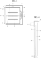
- FIG. 1 is a view showing an oven according to an embodiment of the present invention
- FIG. 2 is a view showing a state of opening the door of an oven according to an embodiment of the present invention
- FIG. 3 is a cross-sectional view taken along line A-A' of FIG. 1 .
- FIGS. 1 to 3 show the configuration of the oven 1.
- the oven 1 includes a case 10 forming appearance thereof and a door 20 attached to one surface of the case 10.
- the case 10 has an internal space and a front side thereof is opened.
- the case 10 may be formed in a predetermined box shape and may include a power supply 14, an input unit 15 and a display 16 provided to a user at the outside thereof.
- the power supply 14 may have various shapes to allow a user to turn on/off the oven 1.
- the input unit 15 is provided with a plurality of buttons to allow the user to select various modes, a temperature, a time and the like.
- the display 16 may be understood as a component for visualizing predetermined information such that the user determines the state of the oven 1.
- the display 16 may be turned on/off according to ON/OFF of the power supply 14 and may be provided in the form of a predetermined panel. The display 16 will be described in detail below.
- a cooking chamber 11 in which food is accommodated is formed in the case 10.
- a grill 12, on which food is placed, may be provided in the cooking chamber 11.
- grill mounting portions 13 may be provided on inner sidewalls of the cooking chamber 11 such that the grill is detachably installed. The number and shape of grills 12 and the grill mounting portions 13 may be variously changed.
- a heating unit 17, a fan 18 and a fan motor 19 for providing driving force to the fan 18 are disposed inside the case 10 and outside the cooking chamber 11.
- the heating unit 17 heats the inside of the cooking chamber 11 and the fan 18 is understood as a component for flowing air in the cooking chamber 11.
- the heating unit 17 may include an electric heater for dissipating heat by electric input and may be installed at one side of the case 10.
- the heating unit 17 may be installed at one side of the fan 18 and may be configured integrally with the fan 18.
- the fan 18 receives driving force from the fan motor 19 to flow air heated by the heating unit 17 in the cooking chamber 11.
- the heating unit 17 and the fan 18 may be understood as components for cooking food in the cooking chamber 11, and the shapes thereof are merely exemplary and may be variously changed.
- the oven 1 according to the embodiment of the present disclosure is not limited to the electric oven using electricity using a heat source and may cook food using various heat sources such as gas- or electronic-type heat source.
- the door 20 is disposed on the open front surface of the case 10 to open and close the cooking chamber 11. That is, the cooking chamber 11 may be opened and closed by the door 20.
- the configuration related to the installation structure and locking device of the door 20 may be omitted.
- the door 20 is installed on the front surface of the case 10 to be rotatable forward.
- the door 20 may be provided with a handle 21 capable of being gripped and rotated by the user.
- the oven 1 may be provided with a predetermined detector capable of detecting the internal state of the cooking chamber 11.
- the detector may include a camera 32 capable of photographing the inside of the cooking chamber 11.
- the camera 32 may be disposed at one side of the cooking chamber 11 to provide the image of the inside of the cooking chamber 11.
- FIG. 3 exemplarily illustrates the camera 32 disposed on the outer upper side of the cooking chamber 11.
- the number and positions of cameras 32 may be variously changed to photograph the inside of the cooking chamber 11, thereby generating the internal image of the cooking chamber 11.
- FIG. 4 is a view showing operation of a display installed in an oven according to the invention.
- the door 20 is formed of a plurality of plates.
- the plates include an outer plate 24 forming the appearance of the oven 1, an inner plate 26 in contact with the cooking chamber 11 and an intermediate plate 28 disposed between the outer plate 24 and the inner plate 26.
- the intermediate plate 28 may be omitted or a plurality of intermediate plates may be provided.
- the intermediate plate 28 may be omitted or a plurality of intermediate plates may be provided.
- one intermediate plate 28 is provided.
- the outer plate 24, the inner plate 26 and the intermediate plate 28 have predetermined thicknesses such that heat in the cooking chamber 11 is not transmitted to the outside.
- the plates 24, 26 and 28 are composed of transparent glass plates such that the user views the cooking chamber 11 via the door 20.
- the plates may be spaced apart from each other at predetermined intervals to form an air passage for minimizing heat transmission.
- a first air passage 23 is formed between the outer plate 24 and the intermediate plate 28 and a second air passage 25 is formed between the intermediate plate 28 and the inner plate 26.
- air introduced from the lower portion of the door 20 is discharged to the upper portion of the door 20 via the air passages 23 and 25, thereby preventing heating of the door 20.
- the oven 1 according to the invention is provided with the display 40 installed in the door 20 to visualize predetermined information to the user.
- the display installed in the case 10 is referred to as a case display 16 and the display installed in the door 20 is referred to as a door display 40.
- the oven 1 includes the display for visualizing predetermined information to the user, and the display may include the case display 16 and includes the door display 40. At this time, the case display 16 may be omitted (see FIG. 9 ).
- the door display 40 is provided to project the image having predetermined information. That is, the door display 40 is understood as a projection module for projecting an image as a type of a head up display (HUD).
- HUD head up display
- the door display 40 may be at least one of a liquid crystal display (LCD), a thin film transistor liquid crystal display (TFT LCD), an organic light-emitting diode (OLED), a flexible display, a third-dimensional (3D) display or an e-ink display.
- LCD liquid crystal display
- TFT LCD thin film transistor liquid crystal display
- OLED organic light-emitting diode
- flexible display a third-dimensional (3D) display or an e-ink display.
- the door display 40 is installed inside the door 20. That is, the door display 40 is disposed between the outer plate 24 and the inner plate 26. In addition, the door display 40 may be disposed below the intermediate plate 28.
- the door display 40 displays an image on the outer plate 24. Specifically, as shown in FIG. 4 , the door display 40 projects the image onto the inner surface of the outer plate 24, that is, one surface forming the first air passage 23.
- the outer plate 24 is made of a transparent material such as glass, such that the image displayed by the door display 40 can be viewed at the outer surface of the outer plate 24, that is, the outside of the oven 1.
- the door display 40 may display the image of the inside of the cooking chamber 11 photographed by the camera in addition to the predetermined image. Therefore, the user may intuitively check the state of the cooking chamber 11 without observing the cooking chamber 11 via the door 20.
- the door display 40 may be provided in various shapes.
- the door display 40 may include a driving unit to adjust a projection angle. Therefore, the size and position of the image projected onto the door 20 may be changed.
- the door 20 may be provided with a predetermined input panel, such that the user inputs a predetermined command by touching an image projected by the door display 40.
- a reflector may be further provided.
- the reflector may be a prism to reflect projected light at a predetermined angle with a predetermined size.
- the case display 16 is provided as a predetermined display panel and thus the position and size of the displayed image are fixed.
- the door display 40 is provided as a module for projecting a predetermined image and thus information may be displayed at various positions with various sizes.
- the display and the door are disposed on the front surface of the oven.
- the case display 16 since the case display 16 is provided in the case 10, information with a relatively small size is visualized. That is, the size of the case display 16 may be limited by the door 20. In contrast, the door display 40 projects the predetermined image onto the door 20 and thus visualizes the information with a relatively large size.
- FIGS. 5 and 6 are views showing the display state of an oven according to the invention.
- the predetermined information is visualized on the front surface of the door 20 by the door display 40.
- the outer plate 24 is made of a transparent material such that the image projected inside the outer plate 24 is visualized to the outside.
- information on the internal temperature and cooking time of the cooking chamber is displayed on the door 20 by the door display 40.
- a time required to cook predetermined food in the cooking chamber 11 is relatively long and user's actions are not relatively often required. Accordingly, the user does not need to stay near the oven 1 and move to a relatively distance place.
- the user may allow food to be cooked in the cooking chamber 11 of the oven 1 located in the kitchen and then move to a living room to watch TV.
- the user may see, in the living room, the oven 1 located in the kitchen, but may not read the information visualized on the case display 16.
- the door display 40 is provided such that cooking information is checked at a long distance, thereby increasing convenience of the user. That is, the door display 40 may provide the cooking information with a larger size to intuitively deliver information to the user.
- the image of the inside of the cooking chamber 11 may be displayed on the door 20 by the door display 40. That is, the image photographed by the camera 32 may be displayed on the door 20 via the door display 40.
- the user can conveniently check the state of cooking predetermined bread in the cooking chamber 11. For example, if cooking is completed when the bread rises, the user can easily check the extent of the rise of the bread via the image.
- the cooking degree of the food can be easily determined by color change and size change of the food, it is possible to determine the state of the food even at a relatively long distance.
- FIG. 7 is a view showing the control configuration of an oven according to an embodiment of the present invention.
- the oven 1 includes a controller 50 for controlling the above-described components.
- the user may transmit a predetermined command to the controller 50 using the power supply 14 and the input unit 15.
- the power supply 14 and the input unit 15 may be provided outside the case 11 as described above or may be provided in the mobile device 60 of the user.
- the controller 50 and the mobile device 60 are connected via Bluetooth, etc. to exchange predetermined information. That is, the user may input a command for controlling the oven 1 at a long distance. For example, the user may preheat the oven 1 using the mobile device 60 and approach the oven 1 to put food into the oven after preheating is completed.
- the controller 50 may receive information detected by a predetermination detector.
- the detector may include the above-described camera 32 and a temperature sensor 30 for measuring the internal temperature of the cooking chamber 11. Specifically, the camera 32 photographs the inside of the cooking chamber 11 and transmit the generated image to the controller 50, and the temperature sensor 30 may transmit the internal temperature information of the cooking chamber 11 to the controller 50.
- the controller 50 may be provided with a timer 52 for measuring a predetermined time.
- the controller 50 may transmit a command to the timer 52 to measure a cooking time when cooking starts or turn on the oven 1 according to a reservation time.
- the controller 50 may operate the heating unit 17 and supply power to the fan motor 19 to drive the fan 18.
- the controller 50 may transmit predetermined information to the display or the mobile device 60 to visualize the predetermined information. For example, the temperature transmitted by the temperature sensor 30 and the cooking time measured by the timer 52 may be visualized.
- the display includes the above-described case display 16 and the door display 40.
- the controller 50 may visualize information on at least one of the case display 16, the door display 40 or the mobile device 60.
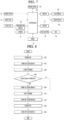
- FIG. 8 is a flowchart illustrating a method of controlling an oven according to an embodiment of the present invention.
- the oven 1 is turned on according to input of the power supply 14 (100).
- the case display 16 is turned on (102) and the user may determine that the oven 1 is turned on.
- the heating unit 17 and the fan 18 are operated, in order for the user to put predetermined food into the oven 1 or to preheat the oven before putting food into the oven. Such a process may be understood as "start cooking 104".
- whether the door display 40 operates is determined (106). For example, when the user continues to watch the oven 1, operation of the door display 40 may not be selected. In addition, the controller 50 may not operate the door display 40 upon determining that power saving is required.
- the door display 40 When operation of the door display 40 is selected, the door display 40 is turned on to project predetermined image onto the door 20 (108). At this time, temperature and time information or image information of the camera 32 may be visualized on the door 20.
- the door display 40 is turned off (112).
- the oven 1 is turned off (114), and the case display 16 is also turned off.
- case display 16 may be turned on/off according to ON/OFF of the oven 1, and the door display 40 may be turned on/off only in certain circumstances.
- FIG. 8 illustrates that the door display 40 is turned on during cooking. This is because, while cooking is performed by the oven 1, the user moves away from the oven 1. Therefore, the door display 40 provides information such that the information is visualized at a relatively long distance.
- the door display 40 may be turned on and operated. This is because, when the door 20 is opened, the user cannot view the information on the door display 40.
- case display 16 may be omitted and information may be visualized only by the door display 40.
- the power supply 14 and the input unit 15 provided in the case 10 may be omitted and an input unit may be provided in the door 20.
- the door 20 may be entirely formed on the front surface of the oven 1. Accordingly, it is possible to provide an oven 1 having cleaner appearance to the user.
- FIG. 9 is a view showing an oven according to another embodiment of the present invention.
- an oven 1a includes a case 10a, a door 20a, a power supply 14a and an input unit 15a.
- the oven 1a may be provided as a handless oven having the door 20a, in which a handle is omitted.
- the door 20a is provided with a door pocket 70 capable of being gripped by the user.
- the door pocket 70 is formed to be recessed downward from the upper surface of the door 20a. Therefore, the door pocket 70 may not be visualized in the front exterior of the oven 1a, thereby providing an oven having cleaner appearance to the user.
- a display (not shown) for projecting a predetermined image is provided inside the door 20a, such that an image projected onto the door 20a is checked by the display.
- a display for projecting a predetermined image is provided inside the door 20a, such that an image projected onto the door 20a is checked by the display.
- the display refer to the description of the above-described door display.
- Predetermined information may be displayed on the door 20a using the door display for projecting the predetermined image even in the oven 1a in which the handle and the case display are omitted.
Landscapes
- Engineering & Computer Science (AREA)
- Physics & Mathematics (AREA)
- Mechanical Engineering (AREA)
- General Engineering & Computer Science (AREA)
- Combustion & Propulsion (AREA)
- Chemical & Material Sciences (AREA)
- General Physics & Mathematics (AREA)
- Electromagnetism (AREA)
- Optics & Photonics (AREA)
- Human Computer Interaction (AREA)
- Signal Processing (AREA)
- Multimedia (AREA)
- Electric Stoves And Ranges (AREA)
- Electric Ovens (AREA)
Claims (13)
- Ofen, der Folgendes umfasst:ein Gehäuse (10);einen Garraum (11), der im Gehäuse (10) gebildet ist; undeine Tür (20), die auf einer Seite des Gehäuses (10) installiert ist, um den Garraum (11) zu öffnen und zu schließen, wobei die Tür (20) Folgendes enthält:eine Außenplatte (24), die das Aussehen bildet;eine Innenplatte (26), die von der Außenplatte (24) um eine vorgegebene Entfernung beabstandet ist und mit dem Garraum (11) in Kontakt ist; undein Türanzeigemodul (40), das zwischen der Außenplatte (24) und der Innenplatte (26) angeordnet ist, um vorgegebene Informationen an der Außenplatte (24) anzuzeigen,dadurch gekennzeichnet, dass das Türanzeigemodul (40) als ein Projektionsmodul zum Projizieren eines vorgegebenen Bilds, das die vorgegebenen Informationen aufweist, an der Außenplatte (24) vorgesehen ist.
- Ofen nach Anspruch 1, wobei das Türanzeigemodul (40) installiert ist, um ein Bild in einer Richtung von dem Garraum (11) zur Tür (20) zu projizieren.
- Ofen nach Anspruch 1 oder 2, wobei das Türanzeigemodul (40) eine Ansteuervorrichtung enthält, die konfiguriert ist, einen Projektionswinkel einzustellen, um eine Größe und eine Position eines projizierten Bilds zu ändern.
- Ofen nach einem der vorhergehenden Ansprüche, wobei das Türanzeigemodul (40) einen Reflektor enthält, der konfiguriert ist, eine Richtung von projiziertem Licht derart zu ändern, dass ein vorgegebenes Bild an der Außenplatte (24) angezeigt wird.
- Ofen nach einem der vorhergehenden Ansprüche, wobei ein Luftdurchlass (23), durch den vorgegebene Luft strömt, zwischen der Außenplatte (24) und der Innenplatte (26) vorgesehen ist und das Türanzeigemodul (40) im Luftdurchlass (23) angeordnet ist.
- Ofen nach einem der vorhergehenden Ansprüche, wobei eine Zwischenplatte (28) zwischen der Außenplatte (24) und der Innenplatte (26) angeordnet ist.
- Ofen nach Anspruch 5 oder 6, wobei der Luftdurchlass einen ersten Luftdurchlass (23), der zwischen der Außenplatte (24) und der Zwischenplatte (28) gebildet ist, und einen zweiten Luftdurchlass (25), der zwischen der Zwischenplatte (28) und der Innenplatte (26) gebildet ist, enthält.
- Ofen nach Anspruch 7, wobei das Türanzeigemodul (40) konfiguriert ist, ein vorgegebenes Bild an einer Oberfläche der Außenplatte (24), die eine Oberfläche des ersten Luftdurchlasses (23) bildet, zu projizieren.
- Ofen nach einem der vorhergehenden Ansprüche, wobei das Türanzeigemodul (40) unter der Zwischenplatte (28) angeordnet ist.
- Ofen nach einem der vorhergehenden Ansprüche, der ferner eine Kamera (32) umfasst, die auf einer Seite des Garraums (11) angeordnet ist, um den Innenraum des Garraums (11) zu fotografieren.
- Ofen nach Anspruch 10, wobei das Türanzeigemodul (40) konfiguriert ist, ein Bild zu projizieren, das durch die Kamera (32) fotografiert wurde.
- Ofen nach einem der vorhergehenden Ansprüche, wobei das Türanzeigemodul (40) konfiguriert ist, ausgeschaltet zu werden, wenn die Tür (20) den Garraum (11) öffnet, und konfiguriert ist, eingeschaltet zu werden, wenn die Tür (20) den Garraum (11) schließt.
- Ofen nach einem der vorhergehenden Ansprüche, der ferner eine Gehäuseanzeigeeinheit (16) umfasst, die auf einer Seite des Gehäuses (10) installiert ist, wobei vorgegebene Informationen an der Gehäuseanzeigeeinheit (10) und/oder dem Türanzeigemodul (40) angezeigt werden.
Priority Applications (1)
| Application Number | Priority Date | Filing Date | Title |
|---|---|---|---|
| EP24183715.2A EP4411249A3 (de) | 2017-07-28 | 2018-07-11 | Backofen mit einem türanzeigemodul |
Applications Claiming Priority (2)
| Application Number | Priority Date | Filing Date | Title |
|---|---|---|---|
| KR1020170096222A KR101955876B1 (ko) | 2017-07-28 | 2017-07-28 | 오븐 및 그의 제어방법 |
| PCT/KR2018/007830 WO2019022410A1 (ko) | 2017-07-28 | 2018-07-11 | 오븐 및 그의 제어방법 |
Related Child Applications (2)
| Application Number | Title | Priority Date | Filing Date |
|---|---|---|---|
| EP24183715.2A Division-Into EP4411249A3 (de) | 2017-07-28 | 2018-07-11 | Backofen mit einem türanzeigemodul |
| EP24183715.2A Division EP4411249A3 (de) | 2017-07-28 | 2018-07-11 | Backofen mit einem türanzeigemodul |
Publications (3)
| Publication Number | Publication Date |
|---|---|
| EP3660404A1 EP3660404A1 (de) | 2020-06-03 |
| EP3660404A4 EP3660404A4 (de) | 2021-04-07 |
| EP3660404B1 true EP3660404B1 (de) | 2024-09-04 |
Family
ID=65039765
Family Applications (2)
| Application Number | Title | Priority Date | Filing Date |
|---|---|---|---|
| EP18838402.8A Active EP3660404B1 (de) | 2017-07-28 | 2018-07-11 | Backofen mit einem türanzeigemodul |
| EP24183715.2A Pending EP4411249A3 (de) | 2017-07-28 | 2018-07-11 | Backofen mit einem türanzeigemodul |
Family Applications After (1)
| Application Number | Title | Priority Date | Filing Date |
|---|---|---|---|
| EP24183715.2A Pending EP4411249A3 (de) | 2017-07-28 | 2018-07-11 | Backofen mit einem türanzeigemodul |
Country Status (4)
| Country | Link |
|---|---|
| US (1) | US12408241B2 (de) |
| EP (2) | EP3660404B1 (de) |
| KR (1) | KR101955876B1 (de) |
| WO (1) | WO2019022410A1 (de) |
Families Citing this family (12)
| Publication number | Priority date | Publication date | Assignee | Title |
|---|---|---|---|---|
| CN108778074B (zh) * | 2016-03-09 | 2022-06-24 | 皇家飞利浦有限公司 | 空气炸锅及空气炸锅的清洁方法 |
| US11287140B2 (en) * | 2019-01-04 | 2022-03-29 | Whirlpool Corporation | Cooking appliance with an imaging device |
| US11022322B2 (en) * | 2019-01-04 | 2021-06-01 | Whirlpool Corporation | Cooking appliance with an imaging device |
| US11156367B2 (en) * | 2020-01-21 | 2021-10-26 | Haier Us Appliance Solutions, Inc. | Oven appliance with an adjustable camera assembly |
| US11940153B2 (en) | 2020-12-01 | 2024-03-26 | GMG Products, LLC | Fuel conditioner for grill |
| KR102910220B1 (ko) * | 2021-04-20 | 2026-01-08 | 엘지전자 주식회사 | 조리기기 |
| US20230018647A1 (en) * | 2021-07-15 | 2023-01-19 | Whirlpool Corporation | Real-time automated cooking cycles system using computer vision and deep learning |
| DE102021126374B3 (de) * | 2021-10-12 | 2022-10-06 | Miele & Cie. Kg | Verfahren und Vorrichtung zum Präsentieren einer Geräteinformation und Haushaltgerät |
| BE1029940B1 (de) * | 2021-11-22 | 2023-06-19 | Miele & Cie | Küchengerät, System mit einem Küchengerät und einer externen Computereinheit und Verfahren zum Betrieb des Küchengeräts oder des Systems |
| CA3245428A1 (en) | 2022-03-03 | 2025-01-21 | GMG Products, LLC | GRILL |
| US12289508B2 (en) | 2022-03-18 | 2025-04-29 | GMG Products, LLC | Detachable camera for a smoker or grill |
| US12359808B1 (en) | 2024-04-30 | 2025-07-15 | GMG Products, LLC | Variable fuel cooker |
Family Cites Families (16)
| Publication number | Priority date | Publication date | Assignee | Title |
|---|---|---|---|---|
| GB1581269A (en) * | 1976-08-17 | 1980-12-10 | M & T Chemicals Inc | Tricyclopentyltin compounds and pesticidal compositions containing same |
| DE20103517U1 (de) * | 2001-02-28 | 2001-05-10 | Rational Ag | Gargerät mit funktionalisierter Gargerätetür |
| DE102004036212A1 (de) | 2004-07-26 | 2006-03-30 | BSH Bosch und Siemens Hausgeräte GmbH | Haushaltsgerätevorbereitung |
| KR100793794B1 (ko) | 2006-04-20 | 2008-01-11 | 엘지전자 주식회사 | 조리기기 |
| WO2009138359A2 (de) | 2008-05-13 | 2009-11-19 | BSH Bosch und Siemens Hausgeräte GmbH | Haushaltsgerät mit bilderfassungsvorrichtung |
| US9297538B2 (en) * | 2008-12-09 | 2016-03-29 | Whirlpool Corporation | Oven door lighting |
| KR101044143B1 (ko) | 2009-06-15 | 2011-06-24 | 엘지전자 주식회사 | 조리기기 |
| FR2956726B1 (fr) * | 2010-02-23 | 2012-03-16 | Fagorbrandt Sas | Appareil electromenager comprenant un dispositif d'affichage |
| DE102012103684B4 (de) * | 2012-04-26 | 2016-09-15 | Miele & Cie. Kg | Haushaltsgerät mit einer Anzeigeeinrichtung |
| KR101844403B1 (ko) * | 2012-09-25 | 2018-04-03 | 삼성전자주식회사 | 조리기기 |
| EP3034948B1 (de) * | 2014-12-19 | 2020-05-27 | Electrolux Appliances Aktiebolag | Ofentür und Ofen mit einer Ofentür |
| EP3256786B1 (de) * | 2015-02-10 | 2020-04-08 | Electrolux Appliances Aktiebolag | Ofentür und ofen mit einer ofentür |
| US9644847B2 (en) * | 2015-05-05 | 2017-05-09 | June Life, Inc. | Connected food preparation system and method of use |
| KR102362654B1 (ko) | 2015-07-03 | 2022-02-15 | 삼성전자주식회사 | 오븐 |
| KR102479811B1 (ko) * | 2016-06-13 | 2022-12-23 | 삼성전자주식회사 | 공기 조화기 및 공기 조화기의 제어방법 |
| DE102017004136A1 (de) * | 2017-05-01 | 2018-11-08 | BSH Hausgeräte GmbH | Haushaltsgerät mit Beleuchtungseinrichtung für Griffmulde |
-
2017
- 2017-07-28 KR KR1020170096222A patent/KR101955876B1/ko active Active
-
2018
- 2018-07-11 US US16/633,458 patent/US12408241B2/en active Active
- 2018-07-11 WO PCT/KR2018/007830 patent/WO2019022410A1/ko not_active Ceased
- 2018-07-11 EP EP18838402.8A patent/EP3660404B1/de active Active
- 2018-07-11 EP EP24183715.2A patent/EP4411249A3/de active Pending
Also Published As
| Publication number | Publication date |
|---|---|
| KR101955876B1 (ko) | 2019-05-30 |
| EP3660404A1 (de) | 2020-06-03 |
| KR20190012746A (ko) | 2019-02-11 |
| EP4411249A3 (de) | 2024-10-16 |
| US12408241B2 (en) | 2025-09-02 |
| WO2019022410A1 (ko) | 2019-01-31 |
| US20200236743A1 (en) | 2020-07-23 |
| EP4411249A2 (de) | 2024-08-07 |
| EP3660404A4 (de) | 2021-04-07 |
Similar Documents
| Publication | Publication Date | Title |
|---|---|---|
| EP3660404B1 (de) | Backofen mit einem türanzeigemodul | |
| KR102399409B1 (ko) | 오븐 및 오븐의 도어 개폐 방법 | |
| US7696454B2 (en) | Cooking apparatus and control method of the same | |
| KR102467319B1 (ko) | 오븐 및 그 제어방법 | |
| EP3252381A1 (de) | Kochvorrichtung und steuerungsverfahren dafür | |
| US11022322B2 (en) | Cooking appliance with an imaging device | |
| US11686477B2 (en) | Cooking appliance with an imaging device | |
| KR101844403B1 (ko) | 조리기기 | |
| ES2818051T3 (es) | Electrodoméstico con interfaz de usuario | |
| US9784457B2 (en) | Oven, door assembly applied to the same, and method for controlling the oven | |
| JP7300587B2 (ja) | 加熱調理器 | |
| KR101644711B1 (ko) | 전자레인지 및 전자레인지의 제어 방법 | |
| KR20160069359A (ko) | 전자레인지 및 전자레인지의 제어 방법 | |
| AU2017273057A1 (en) | Cooking apparatus and controlling method thereof | |
| JP7432829B2 (ja) | 加熱調理器 | |
| JP2009079796A (ja) | 加熱調理器 | |
| JP4646841B2 (ja) | 加熱調理器 | |
| JP2021181869A (ja) | 加熱調理器 | |
| JP2024067246A (ja) | 加熱調理器、コンピュータプログラム及び加熱調理方法 | |
| JP2021032484A (ja) | 加熱調理器 | |
| RU2005122417A (ru) | Микроволновая печь | |
| CN119422029A (zh) | 冰箱和冰箱的控制方法 |
Legal Events
| Date | Code | Title | Description |
|---|---|---|---|
| STAA | Information on the status of an ep patent application or granted ep patent |
Free format text: STATUS: THE INTERNATIONAL PUBLICATION HAS BEEN MADE |
|
| PUAI | Public reference made under article 153(3) epc to a published international application that has entered the european phase |
Free format text: ORIGINAL CODE: 0009012 |
|
| STAA | Information on the status of an ep patent application or granted ep patent |
Free format text: STATUS: REQUEST FOR EXAMINATION WAS MADE |
|
| 17P | Request for examination filed |
Effective date: 20200218 |
|
| AK | Designated contracting states |
Kind code of ref document: A1 Designated state(s): AL AT BE BG CH CY CZ DE DK EE ES FI FR GB GR HR HU IE IS IT LI LT LU LV MC MK MT NL NO PL PT RO RS SE SI SK SM TR |
|
| AX | Request for extension of the european patent |
Extension state: BA ME |
|
| DAV | Request for validation of the european patent (deleted) | ||
| DAX | Request for extension of the european patent (deleted) | ||
| A4 | Supplementary search report drawn up and despatched |
Effective date: 20210304 |
|
| RIC1 | Information provided on ipc code assigned before grant |
Ipc: F24C 3/12 20060101ALI20210226BHEP Ipc: H04N 5/225 20060101ALI20210226BHEP Ipc: G03B 21/56 20060101ALI20210226BHEP Ipc: G03B 21/14 20060101ALI20210226BHEP Ipc: F24C 15/04 20060101AFI20210226BHEP Ipc: F24C 7/08 20060101ALI20210226BHEP Ipc: F24C 15/32 20060101ALI20210226BHEP |
|
| STAA | Information on the status of an ep patent application or granted ep patent |
Free format text: STATUS: EXAMINATION IS IN PROGRESS |
|
| 17Q | First examination report despatched |
Effective date: 20230206 |
|
| REG | Reference to a national code |
Ref country code: DE Ref legal event code: R079 Free format text: PREVIOUS MAIN CLASS: F24C0015040000 Ipc: G03B0021100000 Ref country code: DE Ref legal event code: R079 Ref document number: 602018074077 Country of ref document: DE Free format text: PREVIOUS MAIN CLASS: F24C0015040000 Ipc: G03B0021100000 |
|
| RIC1 | Information provided on ipc code assigned before grant |
Ipc: F24C 7/08 20060101ALI20231221BHEP Ipc: F24C 15/04 20060101ALI20231221BHEP Ipc: H04N 23/57 20230101ALI20231221BHEP Ipc: G03B 29/00 20060101ALI20231221BHEP Ipc: G03B 21/10 20060101AFI20231221BHEP |
|
| GRAP | Despatch of communication of intention to grant a patent |
Free format text: ORIGINAL CODE: EPIDOSNIGR1 |
|
| STAA | Information on the status of an ep patent application or granted ep patent |
Free format text: STATUS: GRANT OF PATENT IS INTENDED |
|
| INTG | Intention to grant announced |
Effective date: 20240221 |
|
| GRAS | Grant fee paid |
Free format text: ORIGINAL CODE: EPIDOSNIGR3 |
|
| GRAA | (expected) grant |
Free format text: ORIGINAL CODE: 0009210 |
|
| STAA | Information on the status of an ep patent application or granted ep patent |
Free format text: STATUS: THE PATENT HAS BEEN GRANTED |
|
| AK | Designated contracting states |
Kind code of ref document: B1 Designated state(s): AL AT BE BG CH CY CZ DE DK EE ES FI FR GB GR HR HU IE IS IT LI LT LU LV MC MK MT NL NO PL PT RO RS SE SI SK SM TR |
|
| REG | Reference to a national code |
Ref country code: GB Ref legal event code: FG4D |
|
| REG | Reference to a national code |
Ref country code: CH Ref legal event code: EP |
|
| REG | Reference to a national code |
Ref country code: IE Ref legal event code: FG4D |
|
| REG | Reference to a national code |
Ref country code: DE Ref legal event code: R096 Ref document number: 602018074077 Country of ref document: DE |
|
| REG | Reference to a national code |
Ref country code: LT Ref legal event code: MG9D |
|
| REG | Reference to a national code |
Ref country code: NL Ref legal event code: MP Effective date: 20240904 |
|
| PG25 | Lapsed in a contracting state [announced via postgrant information from national office to epo] |
Ref country code: NO Free format text: LAPSE BECAUSE OF FAILURE TO SUBMIT A TRANSLATION OF THE DESCRIPTION OR TO PAY THE FEE WITHIN THE PRESCRIBED TIME-LIMIT Effective date: 20241204 |
|
| PG25 | Lapsed in a contracting state [announced via postgrant information from national office to epo] |
Ref country code: PL Free format text: LAPSE BECAUSE OF FAILURE TO SUBMIT A TRANSLATION OF THE DESCRIPTION OR TO PAY THE FEE WITHIN THE PRESCRIBED TIME-LIMIT Effective date: 20240904 Ref country code: FI Free format text: LAPSE BECAUSE OF FAILURE TO SUBMIT A TRANSLATION OF THE DESCRIPTION OR TO PAY THE FEE WITHIN THE PRESCRIBED TIME-LIMIT Effective date: 20240904 Ref country code: GR Free format text: LAPSE BECAUSE OF FAILURE TO SUBMIT A TRANSLATION OF THE DESCRIPTION OR TO PAY THE FEE WITHIN THE PRESCRIBED TIME-LIMIT Effective date: 20241205 |
|
| PG25 | Lapsed in a contracting state [announced via postgrant information from national office to epo] |
Ref country code: BG Free format text: LAPSE BECAUSE OF FAILURE TO SUBMIT A TRANSLATION OF THE DESCRIPTION OR TO PAY THE FEE WITHIN THE PRESCRIBED TIME-LIMIT Effective date: 20240904 |
|
| PG25 | Lapsed in a contracting state [announced via postgrant information from national office to epo] |
Ref country code: LV Free format text: LAPSE BECAUSE OF FAILURE TO SUBMIT A TRANSLATION OF THE DESCRIPTION OR TO PAY THE FEE WITHIN THE PRESCRIBED TIME-LIMIT Effective date: 20240904 |
|
| PG25 | Lapsed in a contracting state [announced via postgrant information from national office to epo] |
Ref country code: HR Free format text: LAPSE BECAUSE OF FAILURE TO SUBMIT A TRANSLATION OF THE DESCRIPTION OR TO PAY THE FEE WITHIN THE PRESCRIBED TIME-LIMIT Effective date: 20240904 |
|
| PG25 | Lapsed in a contracting state [announced via postgrant information from national office to epo] |
Ref country code: ES Free format text: LAPSE BECAUSE OF FAILURE TO SUBMIT A TRANSLATION OF THE DESCRIPTION OR TO PAY THE FEE WITHIN THE PRESCRIBED TIME-LIMIT Effective date: 20240904 Ref country code: RS Free format text: LAPSE BECAUSE OF FAILURE TO SUBMIT A TRANSLATION OF THE DESCRIPTION OR TO PAY THE FEE WITHIN THE PRESCRIBED TIME-LIMIT Effective date: 20241204 |
|
| PG25 | Lapsed in a contracting state [announced via postgrant information from national office to epo] |
Ref country code: RS Free format text: LAPSE BECAUSE OF FAILURE TO SUBMIT A TRANSLATION OF THE DESCRIPTION OR TO PAY THE FEE WITHIN THE PRESCRIBED TIME-LIMIT Effective date: 20241204 Ref country code: PL Free format text: LAPSE BECAUSE OF FAILURE TO SUBMIT A TRANSLATION OF THE DESCRIPTION OR TO PAY THE FEE WITHIN THE PRESCRIBED TIME-LIMIT Effective date: 20240904 Ref country code: NO Free format text: LAPSE BECAUSE OF FAILURE TO SUBMIT A TRANSLATION OF THE DESCRIPTION OR TO PAY THE FEE WITHIN THE PRESCRIBED TIME-LIMIT Effective date: 20241204 Ref country code: LV Free format text: LAPSE BECAUSE OF FAILURE TO SUBMIT A TRANSLATION OF THE DESCRIPTION OR TO PAY THE FEE WITHIN THE PRESCRIBED TIME-LIMIT Effective date: 20240904 Ref country code: HR Free format text: LAPSE BECAUSE OF FAILURE TO SUBMIT A TRANSLATION OF THE DESCRIPTION OR TO PAY THE FEE WITHIN THE PRESCRIBED TIME-LIMIT Effective date: 20240904 Ref country code: GR Free format text: LAPSE BECAUSE OF FAILURE TO SUBMIT A TRANSLATION OF THE DESCRIPTION OR TO PAY THE FEE WITHIN THE PRESCRIBED TIME-LIMIT Effective date: 20241205 Ref country code: FI Free format text: LAPSE BECAUSE OF FAILURE TO SUBMIT A TRANSLATION OF THE DESCRIPTION OR TO PAY THE FEE WITHIN THE PRESCRIBED TIME-LIMIT Effective date: 20240904 Ref country code: ES Free format text: LAPSE BECAUSE OF FAILURE TO SUBMIT A TRANSLATION OF THE DESCRIPTION OR TO PAY THE FEE WITHIN THE PRESCRIBED TIME-LIMIT Effective date: 20240904 Ref country code: BG Free format text: LAPSE BECAUSE OF FAILURE TO SUBMIT A TRANSLATION OF THE DESCRIPTION OR TO PAY THE FEE WITHIN THE PRESCRIBED TIME-LIMIT Effective date: 20240904 |
|
| REG | Reference to a national code |
Ref country code: AT Ref legal event code: MK05 Ref document number: 1720997 Country of ref document: AT Kind code of ref document: T Effective date: 20240904 |
|
| PG25 | Lapsed in a contracting state [announced via postgrant information from national office to epo] |
Ref country code: NL Free format text: LAPSE BECAUSE OF FAILURE TO SUBMIT A TRANSLATION OF THE DESCRIPTION OR TO PAY THE FEE WITHIN THE PRESCRIBED TIME-LIMIT Effective date: 20240904 |
|
| PG25 | Lapsed in a contracting state [announced via postgrant information from national office to epo] |
Ref country code: IS Free format text: LAPSE BECAUSE OF FAILURE TO SUBMIT A TRANSLATION OF THE DESCRIPTION OR TO PAY THE FEE WITHIN THE PRESCRIBED TIME-LIMIT Effective date: 20250104 Ref country code: PT Free format text: LAPSE BECAUSE OF FAILURE TO SUBMIT A TRANSLATION OF THE DESCRIPTION OR TO PAY THE FEE WITHIN THE PRESCRIBED TIME-LIMIT Effective date: 20250106 |
|
| PG25 | Lapsed in a contracting state [announced via postgrant information from national office to epo] |
Ref country code: RO Free format text: LAPSE BECAUSE OF FAILURE TO SUBMIT A TRANSLATION OF THE DESCRIPTION OR TO PAY THE FEE WITHIN THE PRESCRIBED TIME-LIMIT Effective date: 20240904 Ref country code: SM Free format text: LAPSE BECAUSE OF FAILURE TO SUBMIT A TRANSLATION OF THE DESCRIPTION OR TO PAY THE FEE WITHIN THE PRESCRIBED TIME-LIMIT Effective date: 20240904 |
|
| PG25 | Lapsed in a contracting state [announced via postgrant information from national office to epo] |
Ref country code: EE Free format text: LAPSE BECAUSE OF FAILURE TO SUBMIT A TRANSLATION OF THE DESCRIPTION OR TO PAY THE FEE WITHIN THE PRESCRIBED TIME-LIMIT Effective date: 20240904 Ref country code: AT Free format text: LAPSE BECAUSE OF FAILURE TO SUBMIT A TRANSLATION OF THE DESCRIPTION OR TO PAY THE FEE WITHIN THE PRESCRIBED TIME-LIMIT Effective date: 20240904 |
|
| PG25 | Lapsed in a contracting state [announced via postgrant information from national office to epo] |
Ref country code: CZ Free format text: LAPSE BECAUSE OF FAILURE TO SUBMIT A TRANSLATION OF THE DESCRIPTION OR TO PAY THE FEE WITHIN THE PRESCRIBED TIME-LIMIT Effective date: 20240904 |
|
| PG25 | Lapsed in a contracting state [announced via postgrant information from national office to epo] |
Ref country code: SK Free format text: LAPSE BECAUSE OF FAILURE TO SUBMIT A TRANSLATION OF THE DESCRIPTION OR TO PAY THE FEE WITHIN THE PRESCRIBED TIME-LIMIT Effective date: 20240904 Ref country code: IT Free format text: LAPSE BECAUSE OF FAILURE TO SUBMIT A TRANSLATION OF THE DESCRIPTION OR TO PAY THE FEE WITHIN THE PRESCRIBED TIME-LIMIT Effective date: 20240904 |
|
| REG | Reference to a national code |
Ref country code: DE Ref legal event code: R097 Ref document number: 602018074077 Country of ref document: DE |
|
| PG25 | Lapsed in a contracting state [announced via postgrant information from national office to epo] |
Ref country code: DK Free format text: LAPSE BECAUSE OF FAILURE TO SUBMIT A TRANSLATION OF THE DESCRIPTION OR TO PAY THE FEE WITHIN THE PRESCRIBED TIME-LIMIT Effective date: 20240904 |
|
| PLBE | No opposition filed within time limit |
Free format text: ORIGINAL CODE: 0009261 |
|
| STAA | Information on the status of an ep patent application or granted ep patent |
Free format text: STATUS: NO OPPOSITION FILED WITHIN TIME LIMIT |
|
| PGFP | Annual fee paid to national office [announced via postgrant information from national office to epo] |
Ref country code: FR Payment date: 20250611 Year of fee payment: 8 |
|
| 26N | No opposition filed |
Effective date: 20250605 |
|
| PG25 | Lapsed in a contracting state [announced via postgrant information from national office to epo] |
Ref country code: SE Free format text: LAPSE BECAUSE OF FAILURE TO SUBMIT A TRANSLATION OF THE DESCRIPTION OR TO PAY THE FEE WITHIN THE PRESCRIBED TIME-LIMIT Effective date: 20240904 |
|
| PGFP | Annual fee paid to national office [announced via postgrant information from national office to epo] |
Ref country code: DE Payment date: 20250609 Year of fee payment: 8 |
|
| REG | Reference to a national code |
Ref country code: CH Ref legal event code: H13 Free format text: ST27 STATUS EVENT CODE: U-0-0-H10-H13 (AS PROVIDED BY THE NATIONAL OFFICE) Effective date: 20260224 |
|
| PG25 | Lapsed in a contracting state [announced via postgrant information from national office to epo] |
Ref country code: LU Free format text: LAPSE BECAUSE OF NON-PAYMENT OF DUE FEES Effective date: 20250711 |
|
| GBPC | Gb: european patent ceased through non-payment of renewal fee |
Effective date: 20250711 |