EP3659743B1 - Doppelschwenkträgermaschine mit zwei schwenktischen mit einander überlappenden schwenkbereichen sowie zugehöriges bearbeitungsverfahren - Google Patents
Doppelschwenkträgermaschine mit zwei schwenktischen mit einander überlappenden schwenkbereichen sowie zugehöriges bearbeitungsverfahren Download PDFInfo
- Publication number
- EP3659743B1 EP3659743B1 EP18208496.2A EP18208496A EP3659743B1 EP 3659743 B1 EP3659743 B1 EP 3659743B1 EP 18208496 A EP18208496 A EP 18208496A EP 3659743 B1 EP3659743 B1 EP 3659743B1
- Authority
- EP
- European Patent Office
- Prior art keywords
- swivel
- loading
- machine tool
- double
- tables
- Prior art date
- Legal status (The legal status is an assumption and is not a legal conclusion. Google has not performed a legal analysis and makes no representation as to the accuracy of the status listed.)
- Active
Links
Images



Classifications
-
- B—PERFORMING OPERATIONS; TRANSPORTING
- B23—MACHINE TOOLS; METAL-WORKING NOT OTHERWISE PROVIDED FOR
- B23Q—DETAILS, COMPONENTS, OR ACCESSORIES FOR MACHINE TOOLS, e.g. ARRANGEMENTS FOR COPYING OR CONTROLLING; MACHINE TOOLS IN GENERAL CHARACTERISED BY THE CONSTRUCTION OF PARTICULAR DETAILS OR COMPONENTS; COMBINATIONS OR ASSOCIATIONS OF METAL-WORKING MACHINES, NOT DIRECTED TO A PARTICULAR RESULT
- B23Q1/00—Members which are comprised in the general build-up of a form of machine, particularly relatively large fixed members
- B23Q1/25—Movable or adjustable work or tool supports
- B23Q1/64—Movable or adjustable work or tool supports characterised by the purpose of the movement
- B23Q1/66—Worktables interchangeably movable into operating positions
-
- B—PERFORMING OPERATIONS; TRANSPORTING
- B23—MACHINE TOOLS; METAL-WORKING NOT OTHERWISE PROVIDED FOR
- B23Q—DETAILS, COMPONENTS, OR ACCESSORIES FOR MACHINE TOOLS, e.g. ARRANGEMENTS FOR COPYING OR CONTROLLING; MACHINE TOOLS IN GENERAL CHARACTERISED BY THE CONSTRUCTION OF PARTICULAR DETAILS OR COMPONENTS; COMBINATIONS OR ASSOCIATIONS OF METAL-WORKING MACHINES, NOT DIRECTED TO A PARTICULAR RESULT
- B23Q1/00—Members which are comprised in the general build-up of a form of machine, particularly relatively large fixed members
- B23Q1/72—Auxiliary arrangements; Interconnections between auxiliary tables and movable machine elements
- B23Q1/76—Steadies; Rests
Definitions
- the invention relates to a machine tool for the machining of workpieces, in particular, with a double pivoting support rotatably mounted in a machine frame about a main axis, which has two pivoting tables, each rotatably mounted about an A-axis parallel to the main axis of the double pivoting support, for receiving workpieces, one of which
- the pivot table is provided on one processing side and the other pivot table is provided on a loading side, the processing-side pivot table and the loading-side Swivel table are interchangeable by swiveling the double swivel support.
- the invention also relates to an associated machining method.
- Such a double swivel support machine is, for example, by DE 199 13 715 C1 known.
- the processing and loading sides are separated from each other by a rigid partition on the double swivel bracket.
- the object of the invention is to reduce the space requirement in a double swivel support machine of the type mentioned at the outset.
- this object is achieved according to the invention in that the swivel areas of the two swivel tables overlap one another.
- the swiveling table on the machining side is preferably arranged within a machining area and the swiveling table on the loading side is arranged within a loading area.
- both swivel tables do not have to be rotated about their respective swivel axis at the same time.
- a preferred position of the swivel table on the loading side is usually sufficient.
- the distance between the main axis and the A axes is, according to the invention, in each case smaller than the circumferential radius of the swivel tables around their respective A axis. If, on the other hand, the two A-axes are arranged asymmetrically to the main axis, the distance between the two A-axes is smaller than the circumferential diameter of the swivel tables around their respective A-axis.
- the loading-side swivel table is in a loading position that is inclined by a maximum of 20 °, preferably a maximum of 10 °, relative to the vertical, so that the workpiece can be leaned against the loading-side swivel table before it is then hydraulically attached to the Swivel table is clamped.
- the processing side and the loading side of the double pivoting support in the two pivoting end positions of the double pivoting support are permanently separated from each other by a partition or can only be temporarily separated.
- the partition wall protects the loading area from emissions such as cooling lubricant, chips and noise, and has sufficient retention capacity against fragments of damaged tools. If the time for loading and unloading is shorter than the processing time, a temporary separation may be sufficient.
- the double swivel support has two swivel disks, between and on which the two swivel tables are rotatably mounted about their A axes, and the machine frame has two guide grooves between and in which the partition is slidably guided.
- the two swivel disks each have two guide grooves for the partition on the inside on both sides of the main axis.
- the guide groove on the machine frame opens into one of the two guide grooves, so that the partition can be pushed into this guide groove to separate the processing and loading sides asymmetrically to the main axis.
- the partition wall is preferably sealed in the guide grooves of the pivot disks.
- the guide grooves of the side panels each have at least one groove switch in order to divide the two guide grooves into two different groove sections.
- the partition can be pushed into one or the other groove section in order to divide the processing and loading areas in a variable manner.
- the partition wall must be designed to be correspondingly flexible or bendable.
- the partition wall can be designed as a roller shutter, sectional apron or flexible wall, for example.
- the invention also relates to a method for machining workpieces in particular with a machine tool as described above, wherein according to the invention, prior to rotating the machining-side swivel table about its A-axis, the loading-side swivel table is rotated out of the swivel range of the machining-side swivel table.
- the machine tool denoted as a whole by 1
- the machine tool is used for machining workpieces and has a double swivel carrier 4 with two swivel tables 5a , 5b as workpiece carriers , which is pivotably mounted in the frame-like machine frame 2 about a horizontal main axis 3 .
- One swivel table 5a (in Fig. 1 the right one is on the machining side 6 within a machining room and the other swivel table 5b (in Fig. 1 the left) is provided on the loading or equipping side 7 within a loading space.
- the double swivel support 4 has two swivel disks 9 which are mounted on the side of the machine frame 2 about the main axis 3. Between and on the two swivel disks 9, the two swivel tables 5 a, 5 b are each mounted so as to be pivotable about a horizontal pivot axis (A axis) 10 .
- the processing and loading rooms are either self-contained machine rooms or together form a self-contained machine room.
- both swivel tables 5a, 5b do not have to be rotated about their respective A-axis 10 at the same time.
- a vertical or slightly inclined preferred position of the swivel table 5b on the loading side is usually sufficient.
- the distance D between the main axis 3 and the A-axes 10 is therefore smaller than the circumferential radius R of the swivel tables 5a, 5b around their respective A-axis 10, so that the swivel areas 11a, 11b of the two swivel tables 5a, 5b overlap each other.
- the machining-side swivel table 5a Only when the loading-side swivel table 5b is oriented vertically or slightly inclined can the machining-side swivel table 5a be rotated unrestrictedly about its A-axis 10 in the swivel direction 12 , for example by 90 ° or 180 °.
- the two A-axes 10 can also be arranged asymmetrically to the main axis 3;
- the distance between the two A-axes 10 is, according to the invention, smaller than the circumferential diameter of the swivel tables 5a, 5b around their respective A-axis 10.
- the loading-side swivel table 5b which is oriented inclined by approximately 10 ° to 20 °, is equipped with new workpieces 13 on the loading side 7 with the loading door (not shown) open.
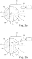
- the swivel table 5a on the machining side is aligned horizontally, and the workpieces 13 held thereon are machined on the machining side 6 by means of a tool held in a horizontal work spindle 14 ( Fig. 2a ).
- the machining-side swivel table 5a is rotated about its A-axis 10 in the swivel direction 12 by 90 ° into a vertical position ( Figure 2b ).
- the swivel table 5a on the machining side is then rotated about its A-axis 10 in the swivel direction 12 by 90 ° into the horizontal machining position ( Fig. 2d ), in which the workpieces 13 held thereon are machined by means of the tool of the work spindle 14.
- the finished workpieces 13 ′ are unloaded from the swivel table 5b on the loading side, and the swivel table 5b on the loading side is again equipped with new workpieces 13.
- the workpieces 13 can also be mounted on the swivel tables 5a, 5b so as to be rotatable about a C-axis at right angles to the A-axis 10.
- a 5-axis double swivel carrier machine is thus obtained.
- the processing and loading sides 6, 7 of the double pivoting support 4 can be separated from one another by a partition 15 in the two pivoting end positions of the double pivoting support 4, i.e. when the processing-side pivoting table 5a is in the processing position and the loading-side pivoting table 5b is in the loading position.
- the partition 15 protects the loading area from emissions such as cooling lubricant, chips, noise, etc. and has a sufficient retention capacity against fragments of damaged tools.
- the machine frame 2 has two guide grooves (or guide slots) 16 between and in which the partition 15 is slidably guided.
- the two pivot disks 9 each have two parallel guide grooves (or guide slots) 17 1 , 17 2 on the inside for the partition 15, which run on both sides of the main axis 10 and at the same distance from the main axis 10.
- the guide groove 16 on the machine frame opens into one of the two guide grooves 17 1 , 17 2 (in Figs. 2a to 2d each in the left), so that the partition 15 can be pushed into the left guide groove in order to separate the processing and loading sides 6, 7 from one another asymmetrically to the main axis 3.
- the partition 15 Before rotating the double pivot bracket 4 about the main axis 3, the partition 15 must be pushed back completely out of the left guide groove. After the double limb support 4 has been given, the loading space is separated from the work space by the partition 15, that is to say the loading space is only temporarily separated from the overall space. The partition 15 is sealed in the guide grooves 17 1 , 17 2 or with respect to the pivot disks 9.
- the guide groove 16 on the machine frame side has a non-rectilinear guide section — here only curved in a 1 ⁇ 4-circle by way of example — so that the partition 15 must be designed to be correspondingly flexible or bendable.
- the partition wall 16 can be designed, for example, as a roller shutter that can be unwound or rolled up about an axis running parallel to the main axis, as a flexible link apron or as a flexible wall.
- the guide grooves 17 1 , 17 2 shown additionally have a double groove switch 18 to divide the two guide grooves into a groove section 19a which is radially outer with respect to the main axis 10 and a groove section 19b which is radially inner with respect to the main axis 10.
- the partition 15 can be inserted into the outer or inner groove section 19a, 19b in order to variably divide the processing and loading spaces.
- the two guide grooves 17 1 , 17 2 with their respective groove sections 19a, 19b run point-symmetrically with respect to the main axis 3.
Landscapes
- Engineering & Computer Science (AREA)
- Mechanical Engineering (AREA)
- Machine Tool Units (AREA)
Description
- Die Erfindung betrifft eine Werkzeugmaschine zur insbesondere spanenden Bearbeitung von Werkstücken mit einem in einem Maschinengestell um eine Hauptachse drehbar gelagerten Doppelschwenkträger, welcher zwei, jeweils um eine zur Hauptachse des Doppelschwenkträgers parallele A-Achse drehbar gelagerte Schwenktische zur Aufnahme von Werkstücken aufweist, von denen der eine Schwenktisch auf einer Bearbeitungsseite und der andere Schwenktisch auf einer Beladeseite vorgesehen sind, wobei der bearbeitungsseitige Schwenktisch und der beladeseitige Schwenktisch durch Verschwenken des Doppelschwenkträgers vertauschbar sind. Die Erfindung betrifft ferner ein zugehöriges Bearbeitungsverfahren.
- Eine derartige Doppelschwenkträgermaschine ist beispielsweise durch die
DE 199 13 715 C1 bekannt geworden. Durch eine starre Trennwand am Doppelschwenkträger sind die Bearbeitungs- und Beladeseiten voneinander abgetrennt. - Nachteil von solchen Doppelschwenkträgermaschinen ist der sehr große Schwenkradius des Doppelschwenkträgers. Sehr großen Doppelschwenkträgermaschinen können daher nicht mehr 1-teilig gebaut und transportiert werden.
- Es ist demgegenüber die Aufgabe der Erfindung, bei einer Doppelschwenkträgermaschine der eingangs genannten Art den Platzbedarf zu reduzieren.
- Diese Aufgabe wird bei einer Werkzeugmaschine der eingangs genannten Art erfindungsgemäß dadurch gelöst, dass die Schwenkbereiche der beiden Schwenktische einander überlappen. Bevorzugt sind dabei der bearbeitungsseitige Schwenktisch innerhalb eines Bearbeitungsraumes und der beladeseitige Schwenktisch innerhalb eines Beladeraumes angeordnet.
- Normalerweise müssen nicht gleichzeitig beide Schwenktische um ihre jeweilige Schwenkachse gedreht werden. In der Beladeposition genügt vor allem bei plattenförmigen Teilen meist eine Vorzugsstellung des beladeseitigen Schwenktisches. Durch die erfindungsgemäß einander überlappenden Schwenkbereiche der beiden Schwenktische lässt sich gegenüber bekannten Doppelschwenkträgermaschine der Schwenkradius des Doppelschwenkträgers reduzieren, was eine 1-teilige Bauweise und eine platzsparende Bauweise ermöglicht.
- Sind die beiden A-Achsen symmetrisch zur Hauptachse angeordnet, ist der Abstand zwischen der Hauptachse und den A-Achsen erfindungsgemäß jeweils kleiner als der Umkreisradius der Schwenktische um ihre jeweilige A-Achse. Sind die beiden A-Achsen hingegen asymmetrisch zur Hauptachse angeordnet, ist der Abstand der beiden A-Achsen erfindungsgemäß kleiner als der Umkreisdurchmesser der Schwenktische um ihre jeweilige A-Achse.
- Zum Auflegen von insbesondere plattenförmigen Werkstücken ist es vorteilhaft, wenn sich der beladeseitige Schwenktisch in einer gegenüber der Senkrechten um maximal 20°, bevorzugt maximal 10°, geneigten Beladeposition befindet, um das Werkstück an den beladeseitigen Schwenktisch anlehnen zu können, bevor es dann hydraulisch am Schwenktisch festgespannt wird.
- Vorzugsweise sind die Bearbeitungsseite und die Beladeseite des Doppelschwenkträgers in den beiden Schwenkendpositionen des Doppelschwenkträgers, also wenn sich der bearbeitungsseitige Schwenktisch in Bearbeitungsposition und der beladeseitige Schwenktisch in Beladeposition befinden, durch eine Trennwand voneinander dauerhaft abgetrennt oder nur temporär abtrennbar. Die Trennwand schützt den Beladebereich vor Emissionen, wie Kühlschmierstoff, Späne und Lärm, und besitzt eine ausreichende Rückhaltefähigkeit gegenüber Bruchteilen von beschädigten Werkzeugen. Falls die Zeit für den Be- und Entladevorgang kleiner als die Bearbeitungszeit ist, genügt unter Umständen eine temporäre Abtrennung.
- In einer besonders bevorzugten Ausführungsform der Erfindung weist der Doppelschwenkträger zwei Schwenkscheiben, zwischen und an denen die beiden Schwenktische um ihre A-Achsen drehbar gelagert sind, und das Maschinengestell zwei Führungsnuten auf, zwischen und in denen die Trennwand verschiebbar geführt ist. Die beiden Schwenkscheiben haben innenseitig zu beiden Seiten der Hauptachse jeweils zwei Führungsnuten für die Trennwand. In den beiden Schwenkendpositionen des Doppelschwenkträgers mündet die maschinengestellseitige Führungsnut jeweils in eine der beiden Führungsnuten, so dass die Trennwand in diese Führungsnut eingeschoben werden kann, um die Bearbeitungs- und Beladeseiten asymmetrisch zur Hauptachse voneinander abzutrennen. Vorzugsweise ist die Trennwand in den Führungsnuten der Schwenkscheiben abgedichtet.
- In einer vorteilhaften Weiterbildung dieser Ausführungsform weisen die Führungsnuten der Seitenscheiben jeweils mindestens eine Nutweiche auf, um die beiden Führungsnuten jeweils in zwei unterschiedliche Nutabschnitte aufzuteilen. Je nach Bedarf kann die Trennwand in den einen oder anderen Nutabschnitt eingeschoben werden, um so die Bearbeitungs- und Beladeräume variabel aufzuteilen. Insbesondere wenn die maschinengestellseitige Führungsnuten oder die Führungsnuten der Seitenscheiben einen nicht-geradlinigen Führungsabschnitt aufweisen, muss die Trennwand entsprechend biegsam oder biegbar ausgeführt sein. Dazu kann die Trennwand beispielsweise als Rollladen, Gliederschürze oder biegsame Wand ausgebildet sein.
- Die Erfindung betrifft in einem weiteren Aspekt auch ein Verfahren zum insbesondere spanenden Bearbeiten von Werkstücken mit einer wie oben beschriebenen Werkzeugmaschine, wobei erfindungsgemäß vor dem Drehen des bearbeitungsseitigen Schwenktisches um seine A-Achse der beladeseitige Schwenktisch aus dem Schwenkbereich des bearbeitungsseitigen Schwenktisches herausgedreht wird.
- Weitere Vorteile der Erfindung ergeben sich aus der Beschreibung und der Zeichnung. Ebenso können die vorstehend genannten und die noch weiter aufgeführten Merkmale erfindungsgemäß jeweils einzeln für sich oder zu mehreren in beliebigen Kombinationen Verwendung finden. Die gezeigten und beschriebenen Ausführungsformen sind nicht als abschließende Aufzählung zu verstehen, sondern haben vielmehr beispielhaften Charakter für die Schilderung der Erfindung. Die Erfindung ist in den Figuren schematisch dargestellt, so dass die wesentlichen Merkmale der Erfindung gut zu erkennen ist. Die Darstellungen sind nicht notwendigerweise maßstäblich zu verstehen.
- Es zeigt:
- Fig. 1
- schematisch eine erfindungsgemäße horizontale Doppelschwenkträgermaschine mit zwei Schwenktischen als Werkstückträger in einer Längsschnittansicht;
- Fign. 2a-2d
- verschiedene Drehstellungen der beiden Schwenktische beim Beladen und Bearbeiten von Werkstücken; und
- Fig. 3
- eine modifizierte Führungsnut für eine Trennwand.
- Die in
Fig. 1 insgesamt mit 1 bezeichnete Werkzeugmaschine dient zur spanenden Bearbeitung von Werkstücken und weist einen im rahmenartigen Maschinengestell 2 um eine horizontale Hauptachse 3 schwenkbar gelagerten Doppelschwenkträger 4 mit zwei Schwenktischen 5a, 5b als Werkstückträger auf. Der eine Schwenktisch 5a (inFig. 1 der rechte) ist auf der Bearbeitungsseite 6 innerhalb eines Bearbeitungsraums und der andere Schwenktisch 5b (inFig. 1 der linke) auf der Belade- oder Bestückungsseite 7 innerhalb eines Beladeraums vorgesehen. Durch pendelndes Verschwenken (Pfeilrichtung 8) des Doppelschwenkträgers 4 um die Hauptachse 3 um 180° lassen sich der bearbeitungsseitige Schwenktisch 5a und der beladeseitige Schwenktisch 5b vertauschen. Der Doppelschwenkträger 4 weist zwei Schwenkscheiben 9 auf, welche seitlich am Maschinengestell 2 um die Hauptachse 3 gelagert sind. Zwischen und an den beiden Schwenkscheiben 9 sind die beiden Schwenktische 5a, 5b jeweils um eine horizontale Schwenkachse (A-Achse) 10 verschwenkbar gelagert. Die Bearbeitungs- und Beladeräume sind entweder jeweils in sich geschlossene Maschinenräume oder bilden gemeinsam einen in sich geschlossenen Maschinenraum. - Normalerweise müssen nicht gleichzeitig beide Schwenktische 5a, 5b um ihre jeweilige A-Achse 10 gedreht werden. In der Beladeposition genügt vor allem bei plattenförmigen Werkstücken meist eine vertikale oder leicht geneigte Vorzugsstellung des beladeseitigen Schwenktisches 5b. Für eine platzsparende Bauweise ist daher der Abstand D zwischen der Hauptachse 3 und den A-Achsen 10 jeweils kleiner als der Umkreisradius R der Schwenktische 5a, 5b um ihre jeweilige A-Achse 10, so dass die Schwenkbereiche 11a, 11b der beiden Schwenktische 5a, 5b einander überlappen. Nur dann, wenn der beladeseitige Schwenktisch 5b vertikal oder leicht geneigt ausgerichtet ist, kann der bearbeitungsseitige Schwenktisch 5a um seine A-Achse 10 in Schwenkrichtung 12 uneingeschränkt, z.B. um 90° oder 180°, gedreht werden.
- Statt wie in
Fig. 1 symmetrisch zur Hauptachse 3, können die beiden A-Achsen 10 auch asymmetrisch zur Hauptachse 3 angeordnet sein; in diesem Fall ist der Abstand der beiden A-Achsen 10 erfindungsgemäß kleiner als der Umkreisdurchmesser der Schwenktische 5a, 5b um ihre jeweilige A-Achse 10. - Die Funktionsweise der Werkzeugmaschine 1 wird nachfolgend anhand der
Fign. 2a bis 2d beschrieben. - Der vertikal oder, wie in
Fig. 1 gezeigt, um ca. 10° bis 20° geneigt ausgerichtete beladeseitige Schwenktisch 5b wird bei geöffneter Beladetür (nicht gezeigt) mit neuen Werkstücken 13 auf der Beladeseite 7 bestückt. Der bearbeitungsseitige Schwenktisch 5a ist horizontal ausgerichtet, und die daran gehaltenen Werkstücke 13 werden mittels eines in einer horizontalen Arbeitsspindel 14 aufgenommenen Werkzeuges auf der Bearbeitungsseite 6 bearbeitet (Fig. 2a ). - Wenn die Werkstücke 13' fertig bearbeitet sind, wird der bearbeitungsseitige Schwenktisch 5a um seine A-Achse 10 in Schwenkrichtung 12 um 90° in eine vertikale Stellung gedreht (
Fig. 2b ). - Durch Drehen des Doppelschwenkträgers 4 um die Hauptachse 3 in Schwenkrichtung 8 um 180° werden der bearbeitungsseitige Schwenktisch 5a und der beladeseitige Schwenktisch 5b vertauscht (
Fig. 2c ). - Der nun bearbeitungsseitige Schwenktisch 5a wird anschließend um seine A-Achse 10 in Schwenkrichtung 12 um 90° in die horizontale Bearbeitungsstellung gedreht (
Fig. 2d ), in der die daran gehaltenen Werkstücke 13 mittels des Werkzeugs der Arbeitsspindel 14 bearbeitet werden. Gleichzeitig werden die fertig bearbeiteten Werkstücke 13' von dem nun beladeseitigen Schwenktisch 5b entladen, und der beladeseitige Schwenktisch 5b wird wieder mit neuen Werkstücken 13 bestückt. - Die Werkstücke 13 können an den Schwenktischen 5a, 5b auch um eine zur A-Achse 10 rechtwinklige C-Achse drehbar gelagert sein. Mit der in drei Achsen verfahrbaren Arbeitsspindeln 14, mit den jeweils um ihre A-Achse 10 verschwenkbaren Schwenktischen 5a, 5b und mit der am Schwenktisch um die C-Achse drehbar gelagerten Werkstückaufnahme ergibt sich somit insgesamt eine 5-achsige Doppelschwenkträgermaschine.
- Wie in den
Fign. 2a bis 2d weiter gezeigt, können die Bearbeitungs- und Beladeseiten 6, 7 des Doppelschwenkträgers 4 in den beiden Schwenkendpositionen des Doppelschwenkträgers 4, also wenn sich der bearbeitungsseitige Schwenktisch 5a in Bearbeitungsposition und der beladeseitige Schwenktisch 5b in Beladeposition befinden, durch eine Trennwand 15 voneinander abgetrennt werden. Auf diese Weise kann während des Bearbeitens der Werkstücke 13 auf der Bearbeitungsseite 6 ein neues Werkstück 13 auf der Beladeseite 7 aufgespannt werden, wobei das Bedienungspersonal vor spritzendem Bohrwasser oder herumfliegenden Bohrspänen etc. geschützt ist. Die Trennwand 15 schützt den Beladebereich vor Emissionen wie Kühlschmierstoff, Späne, Lärm etc. und besitzt eine ausreichende Rückhaltefähigkeit gegenüber Bruchteilen von beschädigten Werkzeugen. - Das Maschinengestell 2 weist zwei Führungsnuten (oder Führungskulissen) 16 auf, zwischen und in denen die Trennwand 15 verschiebbar geführt ist. Die beiden Schwenkscheiben 9 weisen innenseitig jeweils zwei parallele Führungsnuten (oder Führungskulissen) 171 , 172 für die Trennwand 15 auf, die zu beiden Seiten der Hauptachse 10 und mit gleichem Abstand zur Hauptachse 10 verlaufen. In den beiden Schwenkendpositionen des Doppelschwenkträgers 4 mündet die maschinengestellseitige Führungsnut 16 jeweils in eine der beiden Führungsnuten 171, 172 (in
Fign. 2a bis 2d jeweils in die linke), so dass die Trennwand 15 in die linke Führungsnut eingeschoben werden kann, um die Bearbeitungs- und Beladeseiten 6, 7 asymmetrisch zur Hauptachse 3 voneinander abzutrennen. Vor dem Drehen des Doppelschwenkträges 4 um die Hauptachse 3 muss die Trennwand 15 vollständig aus der linken Führungsnut zurückgeschoben sein. Nach dem Schenken des Doppelschenkträgers 4 wird der Beladeraum vom Arbeitsraum durch die Trennwand 15 getrennt, d.h., der Beladeraum wird nur temporär vom Gesamtraum abgetrennt. Die Trennwand 15 ist in den Führungsnuten 171, 172 bzw. gegenüber den Schwenkscheiben 9 abgedichtet. - Die maschinengestellseitige Führungsnut 16 weist einen - hier lediglich beispielhaft ¼-kreisförmig gebogenen - nicht-geradlinigen Führungsabschnitt auf, so dass die Trennwand 15 entsprechend biegsam oder biegbar ausgeführt sein muss. Die Trennwand 16 kann dazu beispielsweise als ein Rollladen, der um eine parallel zur Hauptachse verlaufende Achse ab- bzw. aufwickelbar ist, als eine flexible Gliederschürze oder als eine biegsame Wand ausgebildet sein.
- Die in
Fig. 3 gezeigten Führungsnuten 171, 172 weisen zusätzlich eine zweifache Nutweiche 18 auf, um die beiden Führungsnuten jeweils in einen bezüglich der Hauptachse 10 radial äußeren Nutabschnitt 19a und einen bezüglich der Hauptachse 10 radial inneren Nutabschnitt 19b aufzuteilen. Je nach Bedarf kann die Trennwand 15 in den äußeren oder inneren Nutabschnitt 19a, 19b eingeschoben werden, um so die Bearbeitungs- und Beladeräume variabel aufzuteilen. Die beiden Führungsnuten 171, 172 mit ihren jeweiligen Nutabschnitten 19a, 19b verlaufen zueinander punktsymmetrisch zur Hauptachse 3.
Claims (11)
- Werkzeugmaschine (1) zur insbesondere spanenden Bearbeitung von Werkstücken (13) mit einem in einem Maschinengestell (2) um eine Hauptachse (3) drehbar gelagerten Doppelschwenkträger (4), welcher zwei, jeweils um eine zur Hauptachse (3) parallele A-Achse (10) drehbar gelagerte Schwenktische (5a, 5b) zur Aufnahme von Werkstücken (13) aufweist, von denen der eine Schwenktisch (5a) auf einer Bearbeitungsseite (6) und der andere Schwenktisch (5b) auf einer Beladeseite (7) vorgesehen sind, wobei der bearbeitungsseitige Schwenktisch (5a) und der beladeseitige Schwenktisch (5b) durch Verschwenken des Doppelschwenkträgers (4) vertauschbar sind,
dadurch gekennzeichnet,
dass die Schwenkbereiche (11a, 11b) der beiden Schwenktische (5a, 5b) einander überlappen. - Werkzeugmaschine nach Anspruch 1, dadurch gekennzeichnet, dass der Abstand (D) zwischen der Hauptachse (3) und den A-Achsen (10) jeweils kleiner ist als der Umkreisradius (R) der Schwenktische (5a, 5b) um ihre jeweilige A-achse (10).
- Werkzeugmaschine nach Anspruch 1 oder 2, dadurch gekennzeichnet, dass der bearbeitungsseitige Schwenktisch (5a) innerhalb eines Bearbeitungsraumes und der beladeseitige Schwenktisch (5b) innerhalb eines Beladeraumes angeordnet sind.
- Werkzeugmaschine nach einem der vorhergehenden Ansprüche, dadurch gekennzeichnet, dass sich der beladeseitige Schwenktisch (5b) zum Auflegen von insbesondere plattenförmigen Werkstücken (13) in einer gegenüber der Senkrechten um maximal 20°, bevorzugt maximal 10°, geneigten Beladeposition befindet.
- Werkzeugmaschine nach einem der vorhergehenden Ansprüche, dadurch gekennzeichnet, dass die Bearbeitungsseite (6) und die Beladeseite (7) des Doppelschwenkträgers (4) in den beiden Schwenkendpositionen des Doppelschwenkträgers (4) durch eine Trennwand (15) voneinander abtrennbar sind.
- Werkzeugmaschine nach Anspruch 5, dadurch gekennzeichnet, dass der Doppelschwenkträger (4) zwei Schwenkscheiben (9) aufweist, zwischen und an denen die beiden Schwenktische (5a, 5b) um ihre A-Achsen (10) drehbar gelagert sind, dass das Maschinengestell (2) zwei Führungsnuten (16) aufweist, zwischen und in denen die Trennwand (15) verschiebbar geführt ist, und dass die beiden Schwenkscheiben (9) innenseitig zu beiden Seiten der Hauptachse (3) jeweils zwei Führungsnuten (171, 172) für die Trennwand (15) aufweisen, wobei in den beiden Schwenkendpositionen des Doppelschwenkträgers (4) die maschinengestellseitige Führungsnut (16) jeweils in eine der beiden Führungsnuten (171, 172) mündet.
- Werkzeugmaschine nach Anspruch 6, dadurch gekennzeichnet, dass die Führungsnuten (171, 172) der Seitenscheiben (9) jeweils mindestens eine Nutweiche (18) aufweisen.
- Werkzeugmaschine nach Anspruch 6 oder 7, dadurch gekennzeichnet, dass die Trennwand (15) in den Führungsnuten (171, 172) der Schwenkscheiben (9) abgedichtet ist.
- Werkzeugmaschine nach einem der Ansprüche 5 bis 8, dadurch gekennzeichnet, dass die Trennwand (15) um eine parallel zur Hauptachse (3) verlaufende Achse biegbar ist.
- Werkzeugmaschine nach einem der Ansprüche 5 bis 9, dadurch gekennzeichnet, dass die Trennwand (15) als Rollladen, Gliederschürze oder biegsame Wand ausgebildet ist.
- Verfahren zum insbesondere spanenden Bearbeiten von Werkstücken (13) mit einer Werkzeugmaschine (1) nach einem der vorhergehenden Ansprüche, wobei vor dem Drehen des bearbeitungsseitigen Schwenktisches (5a) um seine A-Achse (10) der beladeseitige Schwenktisch (5b) aus dem Schwenkbereich (11a) des bearbeitungsseitigen Schwenktisches (5a) herausgedreht wird.
Priority Applications (3)
| Application Number | Priority Date | Filing Date | Title |
|---|---|---|---|
| EP18208496.2A EP3659743B1 (de) | 2018-11-27 | 2018-11-27 | Doppelschwenkträgermaschine mit zwei schwenktischen mit einander überlappenden schwenkbereichen sowie zugehöriges bearbeitungsverfahren |
| ES18208496T ES2834348T3 (es) | 2018-11-27 | 2018-11-27 | Máquina de soporte de pivotado doble con dos mesas de pivotado con zonas de pivotado que se solapan una a otra así como correspondiente procedimiento de mecanizado |
| CN201911173438.9A CN111215920B (zh) | 2018-11-27 | 2019-11-26 | 带搭接摆转区域的两个摆转台的双摆转支架机及加工方法 |
Applications Claiming Priority (1)
| Application Number | Priority Date | Filing Date | Title |
|---|---|---|---|
| EP18208496.2A EP3659743B1 (de) | 2018-11-27 | 2018-11-27 | Doppelschwenkträgermaschine mit zwei schwenktischen mit einander überlappenden schwenkbereichen sowie zugehöriges bearbeitungsverfahren |
Publications (2)
| Publication Number | Publication Date |
|---|---|
| EP3659743A1 EP3659743A1 (de) | 2020-06-03 |
| EP3659743B1 true EP3659743B1 (de) | 2020-11-11 |
Family
ID=64500211
Family Applications (1)
| Application Number | Title | Priority Date | Filing Date |
|---|---|---|---|
| EP18208496.2A Active EP3659743B1 (de) | 2018-11-27 | 2018-11-27 | Doppelschwenkträgermaschine mit zwei schwenktischen mit einander überlappenden schwenkbereichen sowie zugehöriges bearbeitungsverfahren |
Country Status (3)
| Country | Link |
|---|---|
| EP (1) | EP3659743B1 (de) |
| CN (1) | CN111215920B (de) |
| ES (1) | ES2834348T3 (de) |
Family Cites Families (10)
| Publication number | Priority date | Publication date | Assignee | Title |
|---|---|---|---|---|
| DE19913715C1 (de) | 1999-03-26 | 2000-12-21 | Schwaebische Werkzeugmaschinen | Reinigungsverfahren für die Bestückungsseite einer Werkzeugmaschine und zugehörige Werkzeugmaschine |
| DE19959072A1 (de) * | 1999-12-08 | 2001-06-13 | Ernst Mendrok | Werkzeugmaschine mit schwenkbaren Werkstückträgern |
| DE102006052933B3 (de) * | 2006-11-08 | 2007-10-31 | Schwäbische Werkzeugmaschinen GmbH | Werkzeugmaschine für manuelle Beladung |
| DE102009048012A1 (de) * | 2009-10-02 | 2011-04-14 | Kapp Gmbh | Verfahren zum Betreiben einer Verzahnungs- oder Profilschleifmaschine und Verzahnungs- oder Profilschleifmaschine |
| DE102012107785A1 (de) * | 2012-08-23 | 2014-02-27 | Chiron-Werke Gmbh & Co. Kg | Werkstückwechsler |
| EP2926948B9 (de) * | 2014-04-01 | 2024-07-10 | OFFICINA MECCANICA DOMASO S.p.A. | Luft-Kühlung von Schleifscheiben und Ladeteller von Federendenschleifmaschine |
| CN205237157U (zh) * | 2015-11-20 | 2016-05-18 | 埃马克(中国)机械有限公司 | 用于并行加工的机床 |
| CN106735465A (zh) * | 2015-11-20 | 2017-05-31 | 埃马克(中国)机械有限公司 | 用于并行加工的机床 |
| DE102015014970A1 (de) * | 2015-11-20 | 2017-05-24 | Emag Holding Gmbh | Werkzeugmaschine zur Simultanbearbeitung |
| CN106944989A (zh) * | 2017-04-28 | 2017-07-14 | 重庆都英科技有限公司 | 一种双层交换工作台 |
-
2018
- 2018-11-27 EP EP18208496.2A patent/EP3659743B1/de active Active
- 2018-11-27 ES ES18208496T patent/ES2834348T3/es active Active
-
2019
- 2019-11-26 CN CN201911173438.9A patent/CN111215920B/zh active Active
Non-Patent Citations (1)
| Title |
|---|
| None * |
Also Published As
| Publication number | Publication date |
|---|---|
| ES2834348T3 (es) | 2021-06-17 |
| EP3659743A1 (de) | 2020-06-03 |
| CN111215920A (zh) | 2020-06-02 |
| CN111215920B (zh) | 2022-10-11 |
Similar Documents
| Publication | Publication Date | Title |
|---|---|---|
| DE4446475C2 (de) | Verfahren und Maschine zum Bearbeiten von Werkstücken | |
| EP2947204B1 (de) | Verfahrbare Vorrichtung zum Fräsen von Schienenköpfen und Verfahren zum Wechsel von Schneidplatten bei einer derartigen Vorrichtung | |
| EP3119562B1 (de) | Robotersystem | |
| DE102015206914A1 (de) | Werkzeugmaschine | |
| EP3659744B1 (de) | Werkzeugmaschine mit schräg gestelltem werkstücktisch | |
| DE19907617C2 (de) | Werkzeugmaschine mit Doppelschwenktisch | |
| EP3245024B1 (de) | Werkzeugmaschine mit fördereinrichtung zur abführung von spänen | |
| EP2897764B1 (de) | Werkstückwechsler und werkzeugmaschine mit einem solchen werkstückwechsler | |
| DE102006043358B4 (de) | Abdeckaufbau für eine Werkzeugmaschine | |
| DE4237939A1 (de) | Vorrichtung zum Bearbeiten der Eckverbindungen von Rahmen | |
| DE3320738C2 (de) | Schutzverkleidung für eine Werkzeugmaschine mit einer Beschickungstür | |
| DE2049749A1 (de) | Werkzeugmaschine, insbesondere Dreh bank, mit automatischer Werkzeugwechsel einrichtung | |
| DE102016114999B4 (de) | Spiralenbearbeitungsverfahren und Spiralenbearbeitungsvorrichtung | |
| EP3299119B1 (de) | Nachbearbeitungsverfahren für die bestückungsseite einer werkzeugmaschine und zugehörige werkzeugmaschine | |
| DE102004057256B4 (de) | Vorrichtung zum Einspannen eines Werkstücks | |
| EP3659743A1 (de) | Doppelschwenkträgermaschine mit zwei schwenktischen mit einander überlappenden schwenkbereichen sowie zugehöriges bearbeitungsverfahren | |
| EP1634674B1 (de) | Schutzvorrichtung einer Laserbearbeitungseinheit | |
| DE3639778C2 (de) | Vorrichtung zum Bearbeiten von Kanten von plattenförmigen Werkstücken | |
| DE3141618C2 (de) | Walzgerüstwechselvorrichtung für Walzstraßen | |
| DE202004020485U1 (de) | Palettenwechsler | |
| DE102007044457A1 (de) | Drehmaschine | |
| DE2405954C3 (de) | Vorrichtung zum Wenden unter gleichzeitigem Querfördern von prismatischem oder annähernd prismatischem Walzgut | |
| AT327646B (de) | Maschine zum schneiden von bandern, insbesondere von blechen grosser lange | |
| DE19951411C2 (de) | Vorrichtung zum Schneiden und Einkerben von Profilen | |
| EP2928638B1 (de) | Bearbeitungsstation für bauteile |
Legal Events
| Date | Code | Title | Description |
|---|---|---|---|
| PUAI | Public reference made under article 153(3) epc to a published international application that has entered the european phase |
Free format text: ORIGINAL CODE: 0009012 |
|
| STAA | Information on the status of an ep patent application or granted ep patent |
Free format text: STATUS: REQUEST FOR EXAMINATION WAS MADE |
|
| 17P | Request for examination filed |
Effective date: 20190703 |
|
| AK | Designated contracting states |
Kind code of ref document: A1 Designated state(s): AL AT BE BG CH CY CZ DE DK EE ES FI FR GB GR HR HU IE IS IT LI LT LU LV MC MK MT NL NO PL PT RO RS SE SI SK SM TR |
|
| AX | Request for extension of the european patent |
Extension state: BA ME |
|
| GRAP | Despatch of communication of intention to grant a patent |
Free format text: ORIGINAL CODE: EPIDOSNIGR1 |
|
| STAA | Information on the status of an ep patent application or granted ep patent |
Free format text: STATUS: GRANT OF PATENT IS INTENDED |
|
| INTG | Intention to grant announced |
Effective date: 20200727 |
|
| GRAS | Grant fee paid |
Free format text: ORIGINAL CODE: EPIDOSNIGR3 |
|
| GRAA | (expected) grant |
Free format text: ORIGINAL CODE: 0009210 |
|
| STAA | Information on the status of an ep patent application or granted ep patent |
Free format text: STATUS: THE PATENT HAS BEEN GRANTED |
|
| AK | Designated contracting states |
Kind code of ref document: B1 Designated state(s): AL AT BE BG CH CY CZ DE DK EE ES FI FR GB GR HR HU IE IS IT LI LT LU LV MC MK MT NL NO PL PT RO RS SE SI SK SM TR |
|
| REG | Reference to a national code |
Ref country code: GB Ref legal event code: FG4D Free format text: NOT ENGLISH |
|
| REG | Reference to a national code |
Ref country code: CH Ref legal event code: EP |
|
| REG | Reference to a national code |
Ref country code: AT Ref legal event code: REF Ref document number: 1332995 Country of ref document: AT Kind code of ref document: T Effective date: 20201115 |
|
| REG | Reference to a national code |
Ref country code: DE Ref legal event code: R096 Ref document number: 502018002988 Country of ref document: DE |
|
| REG | Reference to a national code |
Ref country code: IE Ref legal event code: FG4D Free format text: LANGUAGE OF EP DOCUMENT: GERMAN |
|
| REG | Reference to a national code |
Ref country code: NL Ref legal event code: MP Effective date: 20201111 |
|
| PG25 | Lapsed in a contracting state [announced via postgrant information from national office to epo] |
Ref country code: NO Free format text: LAPSE BECAUSE OF FAILURE TO SUBMIT A TRANSLATION OF THE DESCRIPTION OR TO PAY THE FEE WITHIN THE PRESCRIBED TIME-LIMIT Effective date: 20210211 Ref country code: GR Free format text: LAPSE BECAUSE OF FAILURE TO SUBMIT A TRANSLATION OF THE DESCRIPTION OR TO PAY THE FEE WITHIN THE PRESCRIBED TIME-LIMIT Effective date: 20210212 Ref country code: RS Free format text: LAPSE BECAUSE OF FAILURE TO SUBMIT A TRANSLATION OF THE DESCRIPTION OR TO PAY THE FEE WITHIN THE PRESCRIBED TIME-LIMIT Effective date: 20201111 Ref country code: PT Free format text: LAPSE BECAUSE OF FAILURE TO SUBMIT A TRANSLATION OF THE DESCRIPTION OR TO PAY THE FEE WITHIN THE PRESCRIBED TIME-LIMIT Effective date: 20210311 Ref country code: FI Free format text: LAPSE BECAUSE OF FAILURE TO SUBMIT A TRANSLATION OF THE DESCRIPTION OR TO PAY THE FEE WITHIN THE PRESCRIBED TIME-LIMIT Effective date: 20201111 |
|
| PG25 | Lapsed in a contracting state [announced via postgrant information from national office to epo] |
Ref country code: PL Free format text: LAPSE BECAUSE OF FAILURE TO SUBMIT A TRANSLATION OF THE DESCRIPTION OR TO PAY THE FEE WITHIN THE PRESCRIBED TIME-LIMIT Effective date: 20201111 Ref country code: IS Free format text: LAPSE BECAUSE OF FAILURE TO SUBMIT A TRANSLATION OF THE DESCRIPTION OR TO PAY THE FEE WITHIN THE PRESCRIBED TIME-LIMIT Effective date: 20210311 Ref country code: LV Free format text: LAPSE BECAUSE OF FAILURE TO SUBMIT A TRANSLATION OF THE DESCRIPTION OR TO PAY THE FEE WITHIN THE PRESCRIBED TIME-LIMIT Effective date: 20201111 Ref country code: SE Free format text: LAPSE BECAUSE OF FAILURE TO SUBMIT A TRANSLATION OF THE DESCRIPTION OR TO PAY THE FEE WITHIN THE PRESCRIBED TIME-LIMIT Effective date: 20201111 Ref country code: BG Free format text: LAPSE BECAUSE OF FAILURE TO SUBMIT A TRANSLATION OF THE DESCRIPTION OR TO PAY THE FEE WITHIN THE PRESCRIBED TIME-LIMIT Effective date: 20210211 |
|
| REG | Reference to a national code |
Ref country code: LT Ref legal event code: MG9D |
|
| REG | Reference to a national code |
Ref country code: ES Ref legal event code: FG2A Ref document number: 2834348 Country of ref document: ES Kind code of ref document: T3 Effective date: 20210617 |
|
| PG25 | Lapsed in a contracting state [announced via postgrant information from national office to epo] |
Ref country code: HR Free format text: LAPSE BECAUSE OF FAILURE TO SUBMIT A TRANSLATION OF THE DESCRIPTION OR TO PAY THE FEE WITHIN THE PRESCRIBED TIME-LIMIT Effective date: 20201111 |
|
| PG25 | Lapsed in a contracting state [announced via postgrant information from national office to epo] |
Ref country code: LU Free format text: LAPSE BECAUSE OF NON-PAYMENT OF DUE FEES Effective date: 20201127 Ref country code: LT Free format text: LAPSE BECAUSE OF FAILURE TO SUBMIT A TRANSLATION OF THE DESCRIPTION OR TO PAY THE FEE WITHIN THE PRESCRIBED TIME-LIMIT Effective date: 20201111 Ref country code: RO Free format text: LAPSE BECAUSE OF FAILURE TO SUBMIT A TRANSLATION OF THE DESCRIPTION OR TO PAY THE FEE WITHIN THE PRESCRIBED TIME-LIMIT Effective date: 20201111 Ref country code: CZ Free format text: LAPSE BECAUSE OF FAILURE TO SUBMIT A TRANSLATION OF THE DESCRIPTION OR TO PAY THE FEE WITHIN THE PRESCRIBED TIME-LIMIT Effective date: 20201111 Ref country code: EE Free format text: LAPSE BECAUSE OF FAILURE TO SUBMIT A TRANSLATION OF THE DESCRIPTION OR TO PAY THE FEE WITHIN THE PRESCRIBED TIME-LIMIT Effective date: 20201111 Ref country code: SK Free format text: LAPSE BECAUSE OF FAILURE TO SUBMIT A TRANSLATION OF THE DESCRIPTION OR TO PAY THE FEE WITHIN THE PRESCRIBED TIME-LIMIT Effective date: 20201111 Ref country code: SM Free format text: LAPSE BECAUSE OF FAILURE TO SUBMIT A TRANSLATION OF THE DESCRIPTION OR TO PAY THE FEE WITHIN THE PRESCRIBED TIME-LIMIT Effective date: 20201111 |
|
| REG | Reference to a national code |
Ref country code: BE Ref legal event code: MM Effective date: 20201130 |
|
| REG | Reference to a national code |
Ref country code: DE Ref legal event code: R097 Ref document number: 502018002988 Country of ref document: DE |
|
| PG25 | Lapsed in a contracting state [announced via postgrant information from national office to epo] |
Ref country code: DK Free format text: LAPSE BECAUSE OF FAILURE TO SUBMIT A TRANSLATION OF THE DESCRIPTION OR TO PAY THE FEE WITHIN THE PRESCRIBED TIME-LIMIT Effective date: 20201111 Ref country code: MC Free format text: LAPSE BECAUSE OF FAILURE TO SUBMIT A TRANSLATION OF THE DESCRIPTION OR TO PAY THE FEE WITHIN THE PRESCRIBED TIME-LIMIT Effective date: 20201111 |
|
| PLBE | No opposition filed within time limit |
Free format text: ORIGINAL CODE: 0009261 |
|
| STAA | Information on the status of an ep patent application or granted ep patent |
Free format text: STATUS: NO OPPOSITION FILED WITHIN TIME LIMIT |
|
| 26N | No opposition filed |
Effective date: 20210812 |
|
| PG25 | Lapsed in a contracting state [announced via postgrant information from national office to epo] |
Ref country code: AL Free format text: LAPSE BECAUSE OF FAILURE TO SUBMIT A TRANSLATION OF THE DESCRIPTION OR TO PAY THE FEE WITHIN THE PRESCRIBED TIME-LIMIT Effective date: 20201111 Ref country code: NL Free format text: LAPSE BECAUSE OF FAILURE TO SUBMIT A TRANSLATION OF THE DESCRIPTION OR TO PAY THE FEE WITHIN THE PRESCRIBED TIME-LIMIT Effective date: 20201111 Ref country code: IE Free format text: LAPSE BECAUSE OF NON-PAYMENT OF DUE FEES Effective date: 20201127 |
|
| PG25 | Lapsed in a contracting state [announced via postgrant information from national office to epo] |
Ref country code: SI Free format text: LAPSE BECAUSE OF FAILURE TO SUBMIT A TRANSLATION OF THE DESCRIPTION OR TO PAY THE FEE WITHIN THE PRESCRIBED TIME-LIMIT Effective date: 20201111 |
|
| PG25 | Lapsed in a contracting state [announced via postgrant information from national office to epo] |
Ref country code: IS Free format text: LAPSE BECAUSE OF FAILURE TO SUBMIT A TRANSLATION OF THE DESCRIPTION OR TO PAY THE FEE WITHIN THE PRESCRIBED TIME-LIMIT Effective date: 20210311 Ref country code: TR Free format text: LAPSE BECAUSE OF FAILURE TO SUBMIT A TRANSLATION OF THE DESCRIPTION OR TO PAY THE FEE WITHIN THE PRESCRIBED TIME-LIMIT Effective date: 20201111 Ref country code: MT Free format text: LAPSE BECAUSE OF FAILURE TO SUBMIT A TRANSLATION OF THE DESCRIPTION OR TO PAY THE FEE WITHIN THE PRESCRIBED TIME-LIMIT Effective date: 20201111 Ref country code: CY Free format text: LAPSE BECAUSE OF FAILURE TO SUBMIT A TRANSLATION OF THE DESCRIPTION OR TO PAY THE FEE WITHIN THE PRESCRIBED TIME-LIMIT Effective date: 20201111 |
|
| PG25 | Lapsed in a contracting state [announced via postgrant information from national office to epo] |
Ref country code: MK Free format text: LAPSE BECAUSE OF FAILURE TO SUBMIT A TRANSLATION OF THE DESCRIPTION OR TO PAY THE FEE WITHIN THE PRESCRIBED TIME-LIMIT Effective date: 20201111 |
|
| REG | Reference to a national code |
Ref country code: CH Ref legal event code: PL |
|
| PG25 | Lapsed in a contracting state [announced via postgrant information from national office to epo] |
Ref country code: BE Free format text: LAPSE BECAUSE OF NON-PAYMENT OF DUE FEES Effective date: 20201130 |
|
| GBPC | Gb: european patent ceased through non-payment of renewal fee |
Effective date: 20221127 |
|
| PG25 | Lapsed in a contracting state [announced via postgrant information from national office to epo] |
Ref country code: LI Free format text: LAPSE BECAUSE OF NON-PAYMENT OF DUE FEES Effective date: 20220630 Ref country code: CH Free format text: LAPSE BECAUSE OF NON-PAYMENT OF DUE FEES Effective date: 20220630 |
|
| PG25 | Lapsed in a contracting state [announced via postgrant information from national office to epo] |
Ref country code: GB Free format text: LAPSE BECAUSE OF NON-PAYMENT OF DUE FEES Effective date: 20221127 |
|
| PGFP | Annual fee paid to national office [announced via postgrant information from national office to epo] |
Ref country code: DE Payment date: 20251126 Year of fee payment: 8 |
|
| PGFP | Annual fee paid to national office [announced via postgrant information from national office to epo] |
Ref country code: AT Payment date: 20251117 Year of fee payment: 8 |
|
| PGFP | Annual fee paid to national office [announced via postgrant information from national office to epo] |
Ref country code: IT Payment date: 20251128 Year of fee payment: 8 |
|
| PGFP | Annual fee paid to national office [announced via postgrant information from national office to epo] |
Ref country code: FR Payment date: 20251125 Year of fee payment: 8 |
|
| PGFP | Annual fee paid to national office [announced via postgrant information from national office to epo] |
Ref country code: ES Payment date: 20251216 Year of fee payment: 8 |