EP3659509A1 - Röntgenbildgebungsvorrichtung, röntgendetektor und röntgenbildgebungssystem - Google Patents
Röntgenbildgebungsvorrichtung, röntgendetektor und röntgenbildgebungssystem Download PDFInfo
- Publication number
- EP3659509A1 EP3659509A1 EP18866813.1A EP18866813A EP3659509A1 EP 3659509 A1 EP3659509 A1 EP 3659509A1 EP 18866813 A EP18866813 A EP 18866813A EP 3659509 A1 EP3659509 A1 EP 3659509A1
- Authority
- EP
- European Patent Office
- Prior art keywords
- ray detector
- ray
- information
- identification information
- imaging apparatus
- Prior art date
- Legal status (The legal status is an assumption and is not a legal conclusion. Google has not performed a legal analysis and makes no representation as to the accuracy of the status listed.)
- Withdrawn
Links
- 238000003384 imaging method Methods 0.000 title claims abstract description 233
- 230000005855 radiation Effects 0.000 claims abstract description 21
- 230000003287 optical effect Effects 0.000 claims description 97
- 238000004891 communication Methods 0.000 claims description 82
- 238000000034 method Methods 0.000 claims description 36
- 238000004590 computer program Methods 0.000 claims description 2
- 230000004913 activation Effects 0.000 description 13
- 230000035945 sensitivity Effects 0.000 description 12
- 238000010586 diagram Methods 0.000 description 8
- 230000004397 blinking Effects 0.000 description 5
- 239000003086 colorant Substances 0.000 description 5
- 241001465754 Metazoa Species 0.000 description 2
- 238000002591 computed tomography Methods 0.000 description 2
- 238000010276 construction Methods 0.000 description 2
- 238000002059 diagnostic imaging Methods 0.000 description 2
- 230000006870 function Effects 0.000 description 2
- 230000000149 penetrating effect Effects 0.000 description 2
- 238000012545 processing Methods 0.000 description 2
- 235000000177 Indigofera tinctoria Nutrition 0.000 description 1
- 230000003213 activating effect Effects 0.000 description 1
- 230000005540 biological transmission Effects 0.000 description 1
- 230000007423 decrease Effects 0.000 description 1
- 230000005684 electric field Effects 0.000 description 1
- 238000003702 image correction Methods 0.000 description 1
- 229940097275 indigo Drugs 0.000 description 1
- COHYTHOBJLSHDF-UHFFFAOYSA-N indigo powder Natural products N1C2=CC=CC=C2C(=O)C1=C1C(=O)C2=CC=CC=C2N1 COHYTHOBJLSHDF-UHFFFAOYSA-N 0.000 description 1
- 238000009434 installation Methods 0.000 description 1
- 150000002500 ions Chemical class 0.000 description 1
- 239000004973 liquid crystal related substance Substances 0.000 description 1
- 238000002595 magnetic resonance imaging Methods 0.000 description 1
- 238000004519 manufacturing process Methods 0.000 description 1
- 238000009659 non-destructive testing Methods 0.000 description 1
- 210000000056 organ Anatomy 0.000 description 1
- 230000005236 sound signal Effects 0.000 description 1
- 239000010409 thin film Substances 0.000 description 1
- 238000012285 ultrasound imaging Methods 0.000 description 1
- 230000000007 visual effect Effects 0.000 description 1
Images


Classifications
-
- A—HUMAN NECESSITIES
- A61—MEDICAL OR VETERINARY SCIENCE; HYGIENE
- A61B—DIAGNOSIS; SURGERY; IDENTIFICATION
- A61B6/00—Apparatus for radiation diagnosis, e.g. combined with radiation therapy equipment
- A61B6/44—Constructional features of apparatus for radiation diagnosis
- A61B6/4494—Means for identifying the diagnostic device
-
- A—HUMAN NECESSITIES
- A61—MEDICAL OR VETERINARY SCIENCE; HYGIENE
- A61B—DIAGNOSIS; SURGERY; IDENTIFICATION
- A61B6/00—Apparatus for radiation diagnosis, e.g. combined with radiation therapy equipment
- A61B6/42—Apparatus for radiation diagnosis, e.g. combined with radiation therapy equipment with arrangements for detecting radiation specially adapted for radiation diagnosis
- A61B6/4208—Apparatus for radiation diagnosis, e.g. combined with radiation therapy equipment with arrangements for detecting radiation specially adapted for radiation diagnosis characterised by using a particular type of detector
-
- A—HUMAN NECESSITIES
- A61—MEDICAL OR VETERINARY SCIENCE; HYGIENE
- A61B—DIAGNOSIS; SURGERY; IDENTIFICATION
- A61B6/00—Apparatus for radiation diagnosis, e.g. combined with radiation therapy equipment
- A61B6/42—Apparatus for radiation diagnosis, e.g. combined with radiation therapy equipment with arrangements for detecting radiation specially adapted for radiation diagnosis
- A61B6/4283—Apparatus for radiation diagnosis, e.g. combined with radiation therapy equipment with arrangements for detecting radiation specially adapted for radiation diagnosis characterised by a detector unit being housed in a cassette
-
- A—HUMAN NECESSITIES
- A61—MEDICAL OR VETERINARY SCIENCE; HYGIENE
- A61B—DIAGNOSIS; SURGERY; IDENTIFICATION
- A61B6/00—Apparatus for radiation diagnosis, e.g. combined with radiation therapy equipment
- A61B6/44—Constructional features of apparatus for radiation diagnosis
- A61B6/4405—Constructional features of apparatus for radiation diagnosis the apparatus being movable or portable, e.g. handheld or mounted on a trolley
-
- A—HUMAN NECESSITIES
- A61—MEDICAL OR VETERINARY SCIENCE; HYGIENE
- A61B—DIAGNOSIS; SURGERY; IDENTIFICATION
- A61B6/00—Apparatus for radiation diagnosis, e.g. combined with radiation therapy equipment
- A61B6/44—Constructional features of apparatus for radiation diagnosis
- A61B6/4429—Constructional features of apparatus for radiation diagnosis related to the mounting of source units and detector units
-
- A—HUMAN NECESSITIES
- A61—MEDICAL OR VETERINARY SCIENCE; HYGIENE
- A61B—DIAGNOSIS; SURGERY; IDENTIFICATION
- A61B6/00—Apparatus for radiation diagnosis, e.g. combined with radiation therapy equipment
- A61B6/46—Apparatus for radiation diagnosis, e.g. combined with radiation therapy equipment with special arrangements for interfacing with the operator or the patient
- A61B6/461—Displaying means of special interest
- A61B6/465—Displaying means of special interest adapted to display user selection data, e.g. graphical user interface, icons or menus
-
- A—HUMAN NECESSITIES
- A61—MEDICAL OR VETERINARY SCIENCE; HYGIENE
- A61B—DIAGNOSIS; SURGERY; IDENTIFICATION
- A61B6/00—Apparatus for radiation diagnosis, e.g. combined with radiation therapy equipment
- A61B6/54—Control of apparatus or devices for radiation diagnosis
-
- A—HUMAN NECESSITIES
- A61—MEDICAL OR VETERINARY SCIENCE; HYGIENE
- A61B—DIAGNOSIS; SURGERY; IDENTIFICATION
- A61B6/00—Apparatus for radiation diagnosis, e.g. combined with radiation therapy equipment
- A61B6/54—Control of apparatus or devices for radiation diagnosis
- A61B6/547—Control of apparatus or devices for radiation diagnosis involving tracking of position of the device or parts of the device
-
- A—HUMAN NECESSITIES
- A61—MEDICAL OR VETERINARY SCIENCE; HYGIENE
- A61B—DIAGNOSIS; SURGERY; IDENTIFICATION
- A61B6/00—Apparatus for radiation diagnosis, e.g. combined with radiation therapy equipment
- A61B6/56—Details of data transmission or power supply, e.g. use of slip rings
Definitions
- the disclosure relates to X-ray imaging apparatuses, X-ray detectors, and X-ray imaging systems including the X-ray imaging apparatuses and the X-ray detectors.
- X-rays are electromagnetic waves having wavelengths of 0.01 to 100 angstroms ( ⁇ ) and, due to their ability to be transmitted through objects, may be widely used in medical apparatuses for imaging the inside of a living body or in non-destructive testing equipment for industrial use.
- a basic principle of an X-ray imaging apparatus is that an internal structure of an object is examined by transmitting X-rays emitted from an X-ray tube (or X-ray source) through an object and detecting a difference in intensities of the transmitted X-rays via an X-ray detector.
- the X-ray imaging apparatus facilitates observation of an internal structure of an object by using a principle in which penetrating power of an X-ray varies depending on the density of the object and atomic numbers of atoms constituting the object. As a wavelength of an X-ray decreases, penetrating power of the X-ray increases and a captured image becomes brighter.
- An X-ray imaging apparatus includes an X-ray tube (or X-ray source) for generating X-rays and emitting the generated X-rays toward an object and an X-ray detector for detecting X-rays that have passed through the object.
- the X-ray tube (or X-ray source) may be movably mounted, and the X-ray detector may be installed in an imaging table or stand or be provided as a portable detector.
- X-ray detectors are distinguished from one another by their identification marks such as numbers displayed on outer surfaces thereof.
- identification marks such as numbers displayed on outer surfaces thereof.
- the X-ray detector when an X-ray detector is inserted into a receptor (e.g., a bucky) of an X-ray imaging apparatus, the X-ray detector cannot be identified by its physical mark thereon since the physical mark is invisible from outside. In other words, a user is inconvenienced in having to remove the X-ray detector from the receptor for identification.
- medical imaging apparatuses configured to detect information about an X-ray detector inserted into a receptor and display the detected information.
- an X-ray imaging apparatus includes: an X-ray radiation device configured to emit X-rays; a receptor into which a first X-ray detector configured to detect the emitted X-rays is inserted; an X-ray detector sensing interface configured to detect whether the first X-ray detector has been inserted into the receptor, acquire first identification (ID) information of the first X-ray detector inserted into the receptor, and generate first position information indicating that the first X-ray detector has been inserted into the receptor; an output interface configured to output information about the first X-ray detector; and a controller configured to control the output interface to output the first position information and the first ID information, wherein the first ID information is ID information set by a workstation of an X-ray imaging system including the X-ray imaging apparatus.
- ID identification
- the first X-ray detector is further configured to output an optical signal corresponding to the first identification information
- the X-ray detector sensing interface includes an optical sensor configured to detect the optical signal
- the controller is further configured to acquire the first identification information based on the detected optical signal.
- the controller is further configured to acquire the first identification information corresponding to a color of the optical signal and control the output interface to output the acquired first identification information as information about the color of the optical signal.
- the first X-ray detector includes a plurality of light sources configured to respectively output optical signals, wherein the optical sensor is further configured to detect the number of light sources from which optical signals are output from among the plurality of light sources in the first X-ray detector, and wherein the controller is further configured to acquire information about a remaining battery capacity of the first X-ray detector based on the detected number of light sources and control the output interface to further output the information about the remaining battery capacity of the first X-ray detector.
- the output interface includes a communication interface configured to transmit the first identification information to a mobile device comprising a display.
- the X-ray detector sensing interface is further configured to acquire information about a status of the first X-ray detector via short-range communication, and wherein the controller is further configured to control the output interface to output the information about the status of the first X-ray detector.
- An X-ray imaging system includes a plurality of X-ray imaging apparatuses, each of which is the X-ray imaging apparatus of claim 1; and a workstation configured to control operations of the plurality of X-ray imaging apparatuses, wherein each of the plurality of X-ray imaging apparatus is configured to acquire first identification information of the first X-ray detector when the first X-ray detector is inserted into the receptor of the X-ray imaging apparatus and generate first position information indicating that the first X-ray detector has been inserted into the receptor, and transmit the first identification information and the first position information to the workstation, and wherein the workstation is configured to control the first X-ray detector to be activated based on the first identification information and the first position information and control the X-ray radiation device to emit X-rays toward the activated first X-ray detector.
- the X-ray imaging apparatus is further configured to detect an optical signal output from the first X-ray detector and acquire, based on the detected optical signal, the first identification information corresponding to the optical signal.
- the X-ray imaging apparatus is further configured to acquire the first identification information corresponding to a color of the optical signal.
- the workstation is further configured to set different pieces of identification information respectively with respect to a plurality of X-ray detectors, wherein the different pieces of identification information respectively correspond to different colors, and wherein each of the plurality of X-ray detectors is configured to output an optical signal of a color corresponding to identification information of a corresponding X-ray detector.
- a method of controlling an X-ray imaging apparatus includes: detecting whether a first X-ray detector has been inserted into a receptor; acquiring first ID information of the first X-ray detector inserted into the receptor from the first X-ray detector; generating first position information indicating that the first X-ray detector has been inserted into the receptor; and outputting the first position information and the first ID information, wherein the first ID information is ID information set by a workstation of an X-ray imaging system including the X-ray imaging apparatus.
- the detecting of the first X-ray detector includes outputting an optical signal corresponding to the first identification information generated by an output interface of the first X-ray detector, and wherein the acquiring of the first identification information includes acquiring the first identification information based on the detected optical signal.
- the acquiring of the first identification information includes acquiring the first identification information corresponding to a color of the optical signal, and wherein the outputting of the first identification information includes outputting the first identification information as information about the color of the optical signal.
- the detecting of the first X-ray detector includes detecting the number of light sources from which optical signals are output, from among a plurality of light sources included in the first X-ray detector and configured to respectively output optical signals, wherein the acquiring of the first identification information includes acquiring information about a remaining battery capacity of the first X-ray detector based on the detected number of light sources, and wherein the outputting of the first identification information includes outputting the information about the remaining battery capacity of the first X-ray detector.
- the method may further include transmitting the first identification information to a mobile device.
- the acquiring of the first identification information includes acquiring information about a status of the first X-ray detector from the first X-ray detector, and wherein the outputting of the first identification information includes outputting the information about the status of the first X-ray detector.
- the method may further include transmitting, to the workstation, the first identification information and the first position information indicating that the first X-ray detector has been inserted into the receptor of the X-ray imaging apparatus, wherein the transmitting is performed by the X-ray imaging apparatus, controlling the first X-ray detector to be activated based on the first identification information and the first position information, wherein the controlling is performed by the workstation, and controlling X-rays to be emitted toward the activated first X-ray detector, wherein the controlling is performed by the workstation.
- the method may further include setting different pieces of identification information respectively with respect to a plurality of X-ray detectors, wherein the setting is performed by the workstation and outputting an optical signal of a color corresponding to identification information of the first X-ray detector, wherein the outputting is performed by the first X-ray detector.
- a computer program product includes a computer-readable storage medium having stored therein instructions to: detect whether a first X-ray detector has been inserted into a receptor; acquire first ID information of the first X-ray detector inserted into the receptor from the first X-ray detector; generate first position information indicating that the first X-ray detector has been inserted into the receptor; and output the first position information and the first ID information, wherein the first ID information is ID information set by a workstation of an X-ray imaging system including the X-ray imaging apparatus.
- an image may include a medical image obtained by a magnetic resonance imaging (MRI) apparatus, a computed tomography (CT) apparatus, an ultrasound imaging apparatus, an X-ray apparatus, or another medical imaging apparatus.
- MRI magnetic resonance imaging
- CT computed tomography
- ultrasound imaging apparatus an ultrasound imaging apparatus
- X-ray apparatus an X-ray apparatus
- an "object” may be a target to be imaged and may include a human, an animal, or a part of a human or animal.
- the object may include a body part (an organ, tissue, etc.) or a phantom.
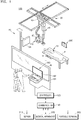
- FIG. 1 is an external view and block diagram of a configuration of an X-ray imaging apparatus 100 according to an embodiment.
- the X-ray imaging apparatus 100 is a fixed X-ray apparatus.
- the X-ray imaging apparatus 100 includes an X-ray radiation device for generating and emitting X-rays, an X-ray detector 200 for detecting X-rays that are emitted by the X-ray radiation device 110 and transmitted through an object P, and a workstation 180 for receiving a command from a user and providing information to the user.
- the X-ray imaging apparatus 100 may further include a controller 120 for controlling the X-ray imaging apparatus 100 according to the received command, and a communication interface 140 for communicating with an external device.
- controller 120 and the communication interface 140 may be included in the workstation 180 or be separate from the workstation 180.
- the X-ray radiation device 110 may include an X-ray source for generating X-rays and a collimator for adjusting a region irradiated with the X-rays generated by the X-ray source.
- a guide rail 30 may be provided on a ceiling of an examination room in which the X-ray imaging apparatus 100 is located, and the X-ray radiation device 110 may be coupled to a moving carriage 40 that is movable along the guide rail 30 such that the X-ray radiation device 110 may be moved to a position corresponding to the object P.
- the moving carriage 40 and the X-ray radiation device 110 may be connected to each other via a foldable post frame 50 such that a height of the X-ray radiation device 110 may be adjusted.
- the workstation 180 may include an input device 181 for receiving a user command and a display 182 for displaying information.
- the input device 181 may receive commands for controlling imaging protocols, imaging conditions, imaging timing, and locations of the X-ray radiation device 110.
- the input device 181 may include a keyboard, a mouse, a touch screen, a microphone, a voice recognizer, etc.
- the display 182 may display a screen for guiding a user's input, an X-ray image, a screen for displaying a state of the X-ray imaging apparatus 100, and the like.
- the controller 120 may control imaging conditions and imaging timing of the X-ray radiation device 110 according to a command input by the user and may generate a medical image based on image data received from an X-ray detector 200. Furthermore, the controller 120 may control a position or orientation of the X-ray radiation device 110 or mounting units (e.g., receptors) and 24, each having the X-ray detector 200 mounted therein, according to imaging protocols and a position of the object P.
- mounting units e.g., receptors
- the controller 120 may include a memory configured to store programs for performing the operations of the X-ray imaging apparatus 100 and a processor or a microprocessor configured to execute the stored programs.
- the controller 120 may include a single processor or a plurality of processors or microprocessors. When the controller 120 includes the plurality of processors, the plurality of processors may be integrated onto a single chip or be physically separated from one another.
- the X-ray imaging apparatus 100 may be connected to external devices such as an external server 310, a medical apparatus 320, and/or a portable terminal 330 (e.g., a mobile device, a smart phone, a tablet PC, or a wearable device) in order to transmit or receive data via the communication interface 140.
- external devices such as an external server 310, a medical apparatus 320, and/or a portable terminal 330 (e.g., a mobile device, a smart phone, a tablet PC, or a wearable device) in order to transmit or receive data via the communication interface 140.
- the communication interface 140 may include at least one component that enables communication with an external device.
- the communication interface 140 may include at least one of a local area communication module, a wired communication module, and a wireless communication module.
- the communication interface 140 may receive a control signal from an external device and transmit the received control signal to the controller 120 so that the controller 120 may control the X-ray imaging apparatus 100 according to the received control signal.
- the controller 120 may control the external device according to the control signal.
- the external device may process data of the external device according to the control signal received from the controller 120 via the communication interface 140.
- the communication interface 140 may further include an internal communication module that enables communications between components of the X-ray imaging apparatus 100.
- a program for controlling the X-ray imaging apparatus 100 may be installed on the external device and may include instructions for performing some or all of the operations of the controller 120.
- the program may be preinstalled on the portable terminal 330, or a user of the portable terminal 330 may download the program from a server providing an application for installation.
- the server that provides applications may include a recording medium where the program is stored.
- the X-ray detector 200 may be implemented as a fixed X-ray detector that is fixedly mounted to a stand 20 or a table 10 or as a portable X-ray detector that may be detachably mounted in the mounting unit 14 or 24 or can be used at arbitrary positions.
- the portable X-ray detector may be implemented as a wired or wireless detector according to a data transmission technique and a power supply method.
- the X-ray detector 200 may or may not be a component of the X-ray imaging apparatus 100. When the X-ray detector 200 is not a component of the X-ray imaging apparatus 100, the X-ray detector 200 may be registered by the user with the X-ray imaging apparatus 100. Furthermore, in both cases, the X-ray detector 200 may be connected to the controller 120 via the communication interface 140 to receive a control signal from or transmit image data to the controller 120.
- a sub-user interface 80 that provides information to a user and receives a command from the user may be provided on one side of the X-ray radiation device 110.
- the sub-user interface 80 may also perform some or all of the functions performed by the input device 181 and the display 182 of the workstation 180.
- controller 120 and the communication interface 140 may be included in the sub-user interface 80 provided on the X-ray radiation device 110.
- FIG. 1 shows a fixed X-ray apparatus connected to the ceiling of the examination room
- examples of the X-ray imaging apparatus 100 may include a C-arm type X-ray apparatus, a mobile X-ray apparatus, and other X-ray apparatuses having various structures that will be apparent to those of ordinary skill in the art.
- FIG. 2 is an external view of the X-ray detector 200.
- the X-ray detector 200 used in the X-ray imaging apparatus 100 may be implemented as a portable X-ray detector.
- the X-ray detector 200 may be equipped with a battery for supplying power to operate wirelessly, or as shown in FIG. 2 , may operate by connecting a charge port 201 to a separate power supply via a cable C.
- a case 203 maintains an external appearance of the X-ray detector 200 and has therein a plurality of detecting elements for detecting X-rays and converting the X-rays into image data, a memory for temporarily or permanently storing the image data, a communication module for receiving a control signal from the X-ray imaging apparatus 100 or transmitting the image data to the X-ray imaging apparatus 100, and a battery. Further, image correction information and intrinsic identification (ID) information of the X-ray detector 200 may be stored in the memory, and the stored ID information may be transmitted together with the image data during communication with the X-ray imaging apparatus 100.
- ID intrinsic identification
- FIG. 3 illustrates an X-ray imaging apparatus 100 and an X-ray detector 200 according to an embodiment.
- an X-ray imaging system may include a plurality of X-ray detectors, a plurality of X-ray imaging apparatuses, and the workstation (180 of FIG. 1 ).
- the workstation 180 may set different pieces of ID information respectively with respect to the plurality of X-ray detectors.
- each of the plurality of X-ray imaging apparatuses may detect whether an X-ray detector has been inserted therein.
- the X-ray imaging apparatus 100 with the X-ray detector 200 inserted therein may acquire ID information from the inserted X-ray detector 200.
- the X-ray imaging apparatus 100 may also generate position information of the X-ray detector 200.
- the position information of the X-ray detector 200 may include information indicating the X-ray imaging apparatus 100 with the X-ray detector 200 inserted therein. ID information and position information of the X-ray detector 200 will be described in more detail below with reference to FIGS. 4 through 9 .
- the workstation 180 may receive ID information and position information of the X-ray detector 200 from the X-ray imaging apparatus 100.
- the workstation 180 may control the X-ray detector 200 to be activated based on the ID information and the position information of the X-ray detector 200.
- the workstation 180 may also control the X-ray radiation device (110 of FIG. 1 ) to emit X-rays toward the activated X-ray detector 200. The operation of the workstation 180 will be described in more detail below with reference to FIGS. 10 and 11 .
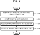
- FIG. 4 is a flowchart of a method of detecting ID information of the X-ray detector 200 and outputting the detected ID information, according to an embodiment.
- the X-ray detector 200 may be inserted into a mounting unit (e.g., receptor (130 of FIG. 5 )) of the X-ray imaging apparatus 100 (S410).
- a mounting unit e.g., receptor (130 of FIG. 5 ) of the X-ray imaging apparatus 100 (S410).
- ID information of the X-ray detector 200 may be set.
- the ID information of the X-ray detector 200 may include visual information that may help a user to select an X-ray detector to be used for X-ray imaging.
- the X-ray detector 200 may include ID information set by the workstation 180 so that the X-ray detector 200 may be distinguished from the other X-ray detectors.
- the workstation 180 may set different pieces of ID information respectively with respect to the plurality of X-ray detectors for use in the X-ray imaging system.
- the workstation 180 may set ID information with respect to the X-ray detector 200 based on unique information of the X-ray detector 200.
- the unique information of the X-ray detector 200 may include a serial number and Internet Protocol (IP) address information of the X-ray detector 200 and other information composed of numerals, letters, or any combination thereof.
- the serial number of the X-ray detector 200 may include a unique identifier assigned to the X-ray detector 200 during a manufacturing process.
- the IP address information of the X-ray detector 200 may include an IP address value to be used for communication between the X-ray detector 200 and a predetermined access point (AP).
- AP access point
- the workstation 180 may register the X-ray detector 200 with the X-ray imaging system. By registering the X-ray detector 200 with the X-ray imaging system, the workstation 180 may allow the registered X-ray detector 200 to communicate with the X-ray imaging apparatus 100 or activate the registered X-ray detector 200.
- the workstation 180 may set ID information with respect to the X-ray detector 200 when registering the X-ray detector 200 with the X-ray imaging system. For example, the workstation 180 may set ID information that is used to distinguish the X-ray detector 200 from other X-ray detectors when the X-ray detector 200 is registered with the X-ray imaging system by using unique information of the X-ray detector 200. The workstation 180 may set ID information of the X-ray detector 200 based on a user input. Furthermore, the workstation 180 may delete and reset the ID information of the X-ray detector 200 based on a user input.
- the workstation 180 may transmit the set ID information to the X-ray detector 200.
- the X-ray detector 200 may then store the set ID information.
- the ID information of the X-ray detector 200 may include letters, numerals, and symbols. Furthermore, the ID information of the X-ray detector 200 may be a color designated by the workstation 180.
- the X-ray detector 200 may output its ID information via an output interface (280 of FIG. 6 ) thereof.
- the output interface 280 of the X-ray detector 200 may include a light source for outputting an optical signal.
- the X-ray detector 200 may output an optical signal of a color set by the workstation 180.
- the X-ray detector 200 may include a light-emitting diode (LED) display, other light-emitting devices, and a liquid crystal display (LCD) for displaying ID information composed of letters, numerals, or any combination thereof.
- LED light-emitting diode
- LCD liquid crystal display
- the X-ray imaging apparatus 100 may detect the X-ray detector 200 that has been inserted into the receptor 130 (S430).
- the X-ray imaging apparatus 100 may detect the X-ray detector 200 that has been inserted into the receptor 130 by using a magnetic sensor.
- the X-ray imaging apparatus 100 and the X-ray detector 200 may each include a magnetic sensor.
- the X-ray imaging apparatus 100 may detect the X-ray detector 200 based on a strength and a direction of an electric field created when the X-ray detector 200 is inserted into the receptor 130 of the X-ray imaging apparatus 100.
- the X-ray imaging apparatus 100 may detect the X-ray detector 200 that has been inserted into the receptor 130 by using a short-range communication method such as Near Field Communication (NFC), radio frequency identification (RFID), and Bluetooth.
- NFC Near Field Communication
- RFID radio frequency identification
- the X-ray imaging apparatus 100 may detect the X-ray detector 200 based on exchange of data generated when the X-ray detector 200 is inserted into the receptor 130.
- the X-ray imaging apparatus 100 may detect the X-ray detector 200 that has been inserted into the receptor 130, based on ID information output from the X-ray detector 200. For example, the X-ray imaging apparatus 100 may detect the X-ray detector 200 that has been inserted into the receptor 130 by detecting an optical signal generated by a light source of the X-ray detector 200.
- the X-ray imaging apparatus 100 may acquire ID information of the X-ray detector 200 inserted into the receptor 130 (S450).
- the X-ray imaging apparatus 100 may acquire ID information of the X-ray detector 200 by receiving the ID information from the X-ray detector 200 via short-range communication such as NFC, RFID, and Bluetooth.
- short-range communication such as NFC, RFID, and Bluetooth.
- the X-ray imaging apparatus 100 may create a short-range communication network with the X-ray detector 200 when the X-ray detector 200 is inserted into the receptor 130.
- the X-ray imaging apparatus 100 may receive the ID information of the X-ray detector 200 from the X-ray detector 200 over the created short-range communication network.
- the X-ray imaging apparatus 100 may acquire the ID information of the X-ray detector 200 based on an optical signal output from the X-ray detector 200.
- the ID information of the X-ray detector 200 may correspond to a color designated by the workstation 180.
- the X-ray detector 200 may output a color designated by the workstation 180 as an optical signal.
- the X-ray imaging apparatus 100 may detect the color of the optical signal output by the X-ray detector 200.
- the X-ray imaging apparatus 100 may acquire the ID information of the X-ray detector 200, which corresponds to the detected color of the optical signal.
- the X-ray imaging apparatus 100 may also acquire information about a status of the X-ray detector 200.
- the information about the status of the X-ray detector 200 may include pieces of information about a remaining battery capacity, an activation state, and communication sensitivity of the X-ray detector 200, information about the number of X-ray images that are to be captured by the X-ray detector 200, and information about whether the X-ray detector 200 is currently transmitting an image to the workstation 180.
- the X-ray imaging apparatus 100 may acquire information about a status of the X-ray detector 200 from the X-ray detector 200 over a short-range communication network created when the X-ray detector 200 is inserted into the receptor 130.
- the X-ray imaging apparatus 100 may also acquire information about a remaining battery capacity of the X-ray detector 200 based on an optical signal output from the X-ray detector 200.
- the X-ray detector 200 may include a plurality of light sources for outputting optical signals.
- the X-ray imaging apparatus 100 may detect the number of light sources from which optical signals are output, among the plurality of light sources in the X-ray detector 200.
- the X-ray imaging apparatus 100 may acquire information about a remaining battery capacity of the X-ray detector 200 based on the detected number of light sources, as will be described below with reference to FIG. 12 .
- the X-ray imaging apparatus 100 may generate position information indicating that the X-ray detector 200 has been inserted into the receptor 130 of the X-ray imaging apparatus 100 (hereinafter, referred to as 'position information of the X-ray detector 200') based on the ID information of the X-ray detector 200.
- the position information of the X-ray detector 200 may include at least one of information indicating that the X-ray detector 200 has been inserted into a receptor of a stand type X-ray imaging apparatus (hereinafter, referred to as 'stand position information'), information indicating that the X-ray detector 200 has been inserted into a receptor of a table type X-ray imaging apparatus (hereinafter, referred to as 'table position information'), and information indicating that the X-ray detector 200 has not fit into any receptor (hereinafter, referred to as 'portable position information').
- the X-ray imaging apparatus 100 may acquire a yellow color as ID information of the X-ray detector 200 set to a yellow color and generate position information indicating that the X-ray imaging apparatus 100 is a stand type X-ray imaging apparatus.
- the X-ray imaging apparatus 100 may output the ID information of the X-ray detector 200 inserted into the receptor 130 (S470).
- the X-ray imaging apparatus 100 may include a display (170 of FIG. 5 ).
- the X-ray imaging apparatus 100 may display on the display 170 at least one of information about whether the X-ray detector 200 has been inserted into the receptor 130 and ID information and position information of the X-ray detector 200 inserted into the receptor 130.
- the X-ray imaging apparatus 100 may include a communication interface (140 of FIG. 1 ).
- the X-ray imaging apparatus 100 may transmit ID information and position information of the X-ray detector 200 to the workstation 180.
- the X-ray imaging apparatus 100 may transmit, to a mobile device (330 of FIG. 8 ), at least one of information about whether the X-ray detector 200 has been inserted into the receptor 130, ID information, and position information of the X-ray detector 200 inserted into the receptor 130.
- the mobile device 330 may display the received at least one piece of information on a display included therein. Displaying of information about the X-ray detector 200 will be described in more detail below with reference to FIGS. 7 through 9 .
- FIG. 5 is a block diagram of a configuration of the X-ray imaging apparatus 100, according to an embodiment.
- the X-ray imaging apparatus 100 may include a controller 120, the receptor 130, an X-ray detector sensing interface 150, and an output interface 160. Furthermore, the output interface 160 of the X-ray imaging apparatus 100 may include a communication interface 140 and the display 170. However, all of the components shown in FIG. 5 are not essential components of the X-ray imaging apparatus 100. It will be understood by those of ordinary skill in the art that the X-ray imaging apparatus 100 may include more or fewer components than those shown in FIG. 5 .
- the X-ray imaging apparatus 100 may further include a storage (not shown) that stores programs for processing and control by the controller 120 and data that is input to or output from the X-ray imaging apparatus 100.
- the controller 120 may control all operations of the receptor 130, the communication interface 140, the X-ray detector sensing interface 150, the output interface 160, the display 170, etc. by executing the programs stored in the storage.
- the controller 120 may acquire ID information and position information of the X-ray detector 200.
- the controller 120 may acquire the ID information of the X-ray detector 200 based on an optical signal from the X-ray detector 200.
- the controller 120 may acquire the ID information of the X-ray detector 200 based on a color of the optical signal.
- the controller 120 may acquire information about a remaining battery capacity of the X-ray detector 200 based on the number of light sources from which optical signals are output among a plurality of light sources in the X-ray detector 200.
- the X-ray detector 200 may be inserted into the receptor 130.
- the receptor 130 may affix the inserted X-ray detector 200 thereto such that the X-ray detector 200 may detect X-rays emitted by the X-ray radiation device (110 of FIG. 1 ).
- the X-ray detector sensing interface 150 may detect whether the X-ray detector 200 has been inserted into the receptor 130.
- the X-ray detector sensing interface 150 may be a magnetic sensor mounted in the receptor 130.
- the X-ray detector sensing interface 150 may be an optical sensor located in the receptor 130.
- the X-ray detector sensing interface 150 may be a short-range communication interface such as an NFC, RFID, or Bluetooth device. Descriptions are already provided above with respect to the method of detecting whether the X-ray detector 200 has been inserted into the receptor 130, and thus, will not be repeated below.
- the X-ray detector sensing interface 150 may acquire ID information of the X-ray detector 200.
- the X-ray detector sensing interface 150 may acquire ID information of the X-ray detector 200 by receiving the ID information of the X-ray detector 200 from the X-ray detector 200 via short-range communication such as NFC, RFID, and Bluetooth.
- the X-ray detector sensing interface 150 may detect a color of an optical signal output from the X-ray detector 200 to thereby acquire ID information of the X-ray detector 200 corresponding to the color of the optical signal. Descriptions are already provided above with respect to the method by which the X-ray detector sensing interface 150 acquires ID information of the X-ray detector 200, and thus, will not be repeated below.
- the X-ray detector sensing interface 150 may generate position information indicating that the X-ray detector 200 has been inserted into the receptor 130.
- the X-ray imaging apparatus 100 may generate, based on the ID information of the X-ray detector 200, position information indicating that the X-ray detector 200 has been inserted into the receptor 130 of the X-ray imaging apparatus 100.
- the position information of the X-ray detector 200 may include at least one of stand position information, table position information, and portable position information.
- the X-ray detector sensing interface 150 may also acquire information about a status of the X-ray detector 200.
- the information about the status of the X-ray detector 200 may include pieces of information about a remaining battery capacity and an activation state of the X-ray detector 200, information about the number of X-ray images that are to be captured by the X-ray detector 200, and information about whether the X-ray detector 200 is currently transmitting an image to the workstation 180.
- the X-ray imaging apparatus 100 may acquire information about a status of the X-ray detector 200 from the X-ray detector 200 over a short-range communication network created when the X-ray detector 200 is inserted into the receptor 130.
- the X-ray imaging apparatus 100 may acquire information about a remaining battery capacity of the X-ray detector 200 based on an optical signal output from the X-ray detector 200. Displaying information about the X-ray detector 200 will be described in more detail below with reference to FIG. 12 .
- the output interface 160 may include the communication interface 140 and the display 170.
- the output interface 160 may further include an audio output interface (not shown) for outputting an audio signal.
- the communication interface 140 may communicate with components constituting the X-ray imaging system.
- the communication interface 140 may communicate with the X-ray detector 200.
- the communication interface 140 may include a module for performing short-range communication such as NFC, RFID, and Bluetooth.
- the communication interface 140 may receive ID information of the X-ray detector 200 from the X-ray detector via short-range communication such as NFC, RFID, and Bluetooth.
- the communication interface 140 may communicate with the workstation 180.
- the communication interface 140 may transmit ID information and position information of the X-ray detector 200 to the workstation 180.
- the communication interface 140 may receive a control signal for controlling the X-ray imaging apparatus 100 from the workstation 180.
- the communication interface 140 may receive a control signal that controls the X-ray detector 200 to be activated from the workstation 180.
- the communication interface 140 may communicate with an external device (e.g., the mobile device 330). For example, the communication interface 140 may transmit ID information and position information of the X-ray detector 200 to the mobile device 330. As another example, the communication interface 140 may transmit information about a status of the X-ray detector 200 to the mobile device 330. Information about a status of the X-ray detector 200 may include pieces of information about a remaining battery capacity and an activation state of the X-ray detector 200, information about the number of X-ray images that are to be captured by the X-ray detector 200, and information about whether the X-ray detector 200 is currently transmitting an image to the workstation 180.
- an external device e.g., the mobile device 330.
- the communication interface 140 may transmit ID information and position information of the X-ray detector 200 to the mobile device 330.
- the communication interface 140 may transmit information about a status of the X-ray detector 200 to the mobile device 330.
- Information about a status of the X-ray detector 200
- the display 170 may output ID information and position information of the X-ray detector 200 by displaying the same. Furthermore, the display 170 may output information about a status of the X-ray detector 200 by displaying the same.
- the information about the status of the X-ray detector 200 may include pieces of information about a remaining battery capacity and an activation state of the X-ray detector 200, information about the number of X-ray images that are to be captured by the X-ray detector 200, and information about whether the X-ray detector 200 is currently transmitting an image to the workstation 180.
- the display 170 may include at least one of an LCD, a thin film transistor-LCD (TFT-LCD), an organic LED (OLED), a flexible display, a three-dimensional (3D) display, and an electrophoretic display.
- LCD liquid crystal display
- TFT-LCD thin film transistor-LCD
- OLED organic LED
- flexible display a three-dimensional (3D) display
- electrophoretic display an electrophoretic display.
- the workstation 180 may control all operations of the X-ray imaging apparatus 100 and the X-ray detector 200 that constitute the X-ray imaging system.
- the workstation 180 may set different pieces of ID information respectively with respect to a plurality of X-ray detectors.
- the workstation 180 may control the X-ray detector 200 to be activated.
- the workstation 180 may also control the X-ray radiation device 110 to emit X-rays toward the activated X-ray detector 200. An operation of the workstation 180 will be described in more detail below with reference to FIG. 10 .
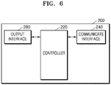
- FIG. 6 is a block diagram of a configuration of the X-ray detector 200 according to an embodiment.
- the X-ray detector 200 may include a controller 220, a communication interface 240, and the output interface 280. However, all of the components shown in FIG. 6 are not essential components of the X-ray detector 200. It will be understood by those of ordinary skill in the art that the X-ray detector 200 may include more or fewer components than those shown in FIG. 6 .
- the X-ray detector 200 may further include a storage (not shown) that stores programs for processing and control by the controller 220 and data that is input to or output from the X-ray detector 200.
- the controller 220 may control all operations of the communication interface 240 and the output interface 280 by executing the programs stored in the storage.
- the communication interface 240 may communicate with components constituting the X-ray imaging system.
- the communication interface 240 may communicate with the X-ray imaging apparatus 100.
- the communication interface 240 may include a module for performing short-range communication such as NFC, RFID, and Bluetooth.
- the communication interface 240 may transmit ID information of the X-ray detector 200 to the X-ray imaging apparatus 100 via short-range communication such as NFC, RFID, and Bluetooth.
- the communication interface 240 may communicate with the workstation 180.
- the communication interface 240 may transmit ID information of the X-ray detector 200 to the workstation 180.
- the communication interface 240 may also transmit information about X-rays detected by the X-ray detector 200 to the workstation 180.
- the communication interface 240 may receive a control signal that controls the X-ray detector 200 to be activated from the workstation 180.
- the communication interface 240 may also transmit unique information of the X-ray detector 200 to the workstation 180.
- the unique information of the X-ray detector 200 may include a serial number and IP address information of the X-ray detector 200 and other information composed of at least one of a letter and a numeral.
- the communication interface 240 may receive ID information of the X-ray detector 200 that is set by the workstation 180 from the workstation 180.
- the communication interface 240 may communicate with an external device (e.g., the mobile device 330). For example, the communication interface 240 may transmit ID information of the X-ray detector 200 to the mobile device 330. As another example, the communication interface 240 may transmit information about a status of the X-ray detector 200 to the mobile device 330. Information about a status of the X-ray detector 200 may include pieces of information about a remaining battery capacity and an activation state of the X-ray detector 200, information about the number of X-ray images that are to be captured by the X-ray detector 200, and information about whether the X-ray detector 200 is currently transmitting an image to the workstation 180.
- the output interface 280 may output ID information of the X-ray detector 200.
- the output interface 280 may include an LED, other light-emitting devices, and an LCD for displaying ID information composed of letters or numerals.
- the output interface 280 may include a plurality of light sources.
- the output interface 280 may output an optical signal.
- the output interface 280 may output an optical signal of a color set by the workstation 180.
- the output interface 280 may output information about a remaining battery capacity of the X-ray detector 200 by using the number of light sources from which optical signals are output among the plurality of light sources.
- the output interface 280 may output information about communication sensitivity of the X-ray detector 200 by using an optical signal output from a light source.
- the output interface 280 may output information about communication sensitivity of the X-ray detector 200 by using a blink period of an optical signal.
- FIG. 7 illustrates an example of displaying information about the X-ray detector 200 inserted into the receptor 130, according to an embodiment.
- the X-ray detector 200 may output its own information.
- the X-ray imaging apparatus 100 may detect an optical signal output from the X-ray detector 200 that has been inserted into the receptor 130 of the X-ray imaging apparatus 100.
- the X-ray imaging apparatus 100 may then acquire ID information of the X-ray detector 200 based on the optical signal and output the acquired ID information.
- the X-ray detector 200 may output its ID information as an optical signal of a color set by the workstation 180.
- the workstation 180 may set colors respectively corresponding to the plurality of X-ray detectors as respective pieces of ID information of the plurality of X-ray detectors.
- the workstation 180 may respectively set the pieces of ID information of the plurality of X-ray detectors to be red, orange, yellow, green, blue, indigo, and violet colors.
- An X-ray detector with its ID information set to a yellow color may output a yellow optical signal.
- the X-ray detector 200 may output information about a remaining battery capacity thereof as an optical signal.
- the X-ray detector 200 may output information about its remaining battery capacity by using the number of light sources from which optical signals are output among a plurality of light sources.
- the X-ray detector 200 may output information about its remaining battery capacity by using a blink period of an optical signal.
- a blink period of an optical signal is less than a first threshold value
- a remaining battery capacity of the X-ray detector 200 may be 80 %When the blink period of the optical signal is greater than or equal to the first threshold value but is less than a second threshold value, the remaining battery capacity of the X-ray detector 200 may be 60 %.
- the X-ray detector 200 may output information about an activation state thereof as an optical signal.
- the X-ray detector 200 may output information about an activation state thereof by using blinking of an optical signal.
- the X-ray detector 200 may indicate that it is in an activated state by outputting a non-blinking optical signal.
- the X-ray detector 200 may also indicate that it is in a standby state waiting for activation by outputting a blinking optical signal.
- the X-ray detector 200 may also indicate that it is transmitting a captured X-ray image by outputting a blinking optical signal.
- the X-ray detector 200 may also indicate that it is in a standby state waiting for a communication connection by outputting a blinking optical signal.
- the X-ray detector 200 may output information about communication sensitivity thereof as an optical signal.
- the output interface 280 may output information about communication sensitivity of the X-ray detector 200 by using a blink period of an optical signal.
- a blink period of an optical signal is less than a first threshold value, the X-ray detector 200 may have high communication sensitivity. Otherwise, when the blink period of the optical signal is greater than or equal to the first threshold value but is less than a second threshold value, the X-ray detector 200 may have low communication sensitivity.
- the X-ray imaging apparatus 100 may detect an optical signal output from the X-ray detector 200 inserted into the receptor 130 of the X-ray imaging apparatus 100.
- the X-ray imaging apparatus 100 may detect a color of an optical signal output from the X-ray detector 200.
- the X-ray imaging apparatus 100 may detect a blink period of an optical signal output from the X-ray detector 200.
- the X-ray imaging apparatus 100 may detect the number of light sources from which optical signals are output among a plurality of light sources included in the X-ray detector 200.
- the X-ray imaging apparatus 100 may acquire ID information of the X-ray detector 200 based on an optical signal.
- the X-ray imaging apparatus 100 may acquire ID information of the X-ray detector 200 based on a color of an optical signal.
- the X-ray imaging apparatus 100 may acquire information about a status of the X-ray detector 200 as well. For example, the X-ray imaging apparatus 100 may acquire at least one of pieces of information about a remaining battery capacity, an activation state, and communication sensitivity of the X-ray detector 200. Furthermore, the X-ray imaging apparatus 100 may acquire information about the number of X-ray images that are to be captured by the X-ray detector 200, based on information about a remaining battery capacity of the X-ray detector 200.
- the X-ray imaging apparatus 100 may output the ID information of the X-ray detector 200.
- the X-ray imaging apparatus 100 may output information about a color that has been set as the ID information of the X-ray detector 200.
- the X-ray imaging apparatus 100 may display ID information of the X-ray detector 200 that has been set to a yellow color as the word "Yellow”.
- the X-ray imaging apparatus 100 may display ID information of the X-ray detector 200, which has been set to a yellow color, as a yellow image.
- the X-ray imaging apparatus 100 may also output information about whether the X-ray detector 200 has been inserted into the receptor 130 and position information of the X-ray detector 200 inserted into the receptor 130.
- the X-ray imaging apparatus 100 may also output information about a status of the X-ray detector 200.
- the X-ray imaging apparatus 100 may output at least one of pieces of information about a remaining battery capacity, an activation state, and communication sensitivity of the X-ray detector 200.
- the X-ray imaging apparatus 100 may output information about the number of X-ray images that are to be captured by the X-ray detector 200.
- FIG. 8 illustrates an example of displaying information about the X-ray detector 200 inserted into the receptor 130 on the mobile device 330, according to an embodiment.
- the X-ray detector 200 may output its own ID information.
- the X-ray imaging apparatus 100 may detect an optical signal output from the X-ray detector 200 inserted into the receptor 130 of the X-ray imaging apparatus 100.
- the X-ray imaging apparatus 100 may acquire ID information of the X-ray detector 200 based on an optical signal.
- the X-ray imaging apparatus 100 may transmit the ID information to the mobile device 330, and the mobile device 330 may output the ID information.
- the X-ray imaging apparatus 100 may transmit ID information of the X-ray detector 200 to the mobile device 330.
- the X-ray imaging apparatus 100 may transmit, to the mobile device 330, information about a color that is set as the ID information of the X-ray detector 200.
- the X-ray imaging apparatus 100 may also transmit, to the mobile device 330, at least one of information about whether the X-ray detector 200 has been inserted into the receptor 130 and position information of the X-ray detector 200 inserted into the receptor 130.
- the X-ray imaging apparatus 100 may also transmit information about a status of the X-ray detector 200 to the mobile device 330.
- the X-ray imaging apparatus 100 may transmit, to the mobile device 330, at least one of pieces of information about a remaining battery capacity, an activation state, and communication sensitivity of the X-ray detector 200.
- the X-ray imaging apparatus 100 may transmit, to the mobile device 330, information about the number of X-ray images that are to be captured by the X-ray detector 200.
- the mobile device 330 may output the received ID information of the X-ray detector 200 via a display included in the mobile device 330. Furthermore, the mobile device 330 may output the information about whether the X-ray detector 200 has been inserted into the receptor 130 and the position information of the X-ray detector 200 inserted into the receptor 130.
- the mobile device 330 may also output the information about the status of the X-ray detector 200. For example, the mobile device 330 may output at least one of pieces of information about a remaining battery capacity, an activation state, and communication sensitivity of the X-ray detector 200. Furthermore, the mobile device 330 may output information about the number of X-ray images that are to be captured by the X-ray detector 200.
- FIG. 9 is an example of displaying information about the X-ray detector 200 inserted into the receptor 130, according to an embodiment.
- the X-ray detector 200 may output its information by transmitting the same to the X-ray imaging apparatus 100.
- the X-ray imaging apparatus 100 may acquire ID information of the X-ray detector 200 from the received information about the X-ray detector 200 and output the acquired ID information.
- the X-ray detector 200 may output its information by transmitting the same to the X-ray imaging apparatus 100.
- the information about the X-ray detector 200 may include ID information of the X-ray detector 200 set by the workstation 180 and information about a status of the X-ray detector 200.
- the information about the status of the X-ray detector 200 may include pieces of information about a remaining battery capacity, an activation state, and communication sensitivity of the X-ray detector 200, information about the number of X-ray images that are to be captured by the X-ray detector 200, and information about whether the X-ray detector 200 is currently transmitting an image to the workstation 180.
- ID information of the X-ray detector 200 may be composed of a letter, a numeral, or any combination thereof.
- ID information of the X-ray detector 200 may be set to be S1, S2, S3, S4, T1, T2, T3, and T4.
- the X-ray detector 200 may transmit information about the X-ray detector 200 to the X-ray imaging apparatus 100 over a short-range communication network created when the X-ray detector 200 is inserted into the receptor 130.
- the X-ray imaging apparatus 100 may acquire ID information of the X-ray detector 200 from the received information about the X-ray detector 200. Furthermore, the X-ray imaging apparatus 100 may acquire information about a status of the X-ray detector 200 from the information about the X-ray detector 200.
- the X-ray imaging apparatus 100 may output ID information of the X-ray detector 200. Since a method by which the X-ray imaging apparatus 100 outputs ID information is similar to the method described with reference to FIG. 7 , descriptions already provided above with respect to FIG. 7 will be omitted here.
- the X-ray imaging apparatus 100 may transmit information about a status of the X-ray detector 200 to the mobile device 330.
- the mobile device 330 may acquire at least one of the pieces of ID information and information about a status of the X-ray detector 200 from information about the X-ray detector 200.
- the mobile device 330 may output the ID information of the X-ray detector 200.
- the mobile device 330 may output information about whether the X-ray detector 200 has been inserted into the receptor 130 and position information of the X-ray detector 200 inserted into the receptor 130.
- the mobile device 330 may output the information about the status of the X-ray detector 200. Since a method by which the mobile device 330 outputs ID information is similar to the method described with reference to FIG. 8 , descriptions already provided above with respect to FIG. 8 will be omitted here.
- FIG. 10 is a diagram for explaining an operation of a workstation 180 according to an embodiment.
- the workstation 180 may control operations of an X-ray detector 200 and an X-ray imaging apparatus 100 included in an X-ray imaging system.
- a plurality of X-ray detectors and a plurality of X-ray imaging apparatuses may be included in the X-ray imaging system.
- the workstation 180 may register a plurality of X-ray detectors with the X-ray imaging system.
- the workstation 180 may register the plurality of X-ray detectors based on pieces of unique information respectively received from the plurality of X-ray detectors.
- Unique information of the X-ray detector 200 may include a serial number and IP address information of the X-ray detector 200 and other information composed of at least one of a numeral and a letter.
- the workstation 180 may set ID information with respect to the X-ray detector.
- the workstation 180 may respectively set pieces of ID information of the plurality of X-ray detectors to be respectively different colors.
- the workstation 180 may set pieces of ID information of the plurality of X-ray detectors to be respectively composed of different letters, numerals, or combinations thereof.
- the workstation 180 may transmit the pieces of ID information respectively set with respect to the plurality of X-ray detectors.
- the workstation 180 may receive ID information and position information of the X-ray detector 200 inserted into a receptor of each of the plurality of X-ray imaging apparatuses.
- position information of the X-ray detector 200 may include at least one of stand position information, table position information, and portable position information.
- the workstation 180 may control the X-ray detector 200 to be activated.
- the workstation 180 may control the X-ray detector 200 to be activated based on ID information and position information of the X-ray detector 200 received from the X-ray imaging apparatus 100.
- the workstation 180 may control the X-ray detector 200 inserted into an X-ray imaging apparatus where an object to be imaged is placed, such that the X-ray detector 200 is activated.
- the workstation 180 may control X-rays to be projected onto the activated X-ray detector 200 based on the received ID information and position information of the X-ray detector 200.
- the workstation 180 may receive from the X-ray detector 200 information about X-rays detected by the X-ray detector 200.
- the workstation 180 may generate an X-ray image based on the information about X-rays.
- a display 182 of the workstation 180 may display a list of the plurality of X-ray detectors registered with the X-ray imaging system on a user interface screen.
- the workstation 180 may display, in the list of the plurality of X-ray detectors, at least one of unique information, ID information and position information of each of the plurality of X-ray detectors.
- the workstation 180 may display at least one of unique information, ID information, and position information of an X-ray detector selected from the list of the plurality of X-ray detectors.
- the workstation 180 may display pieces of ID information 184a and 184b of X-ray detectors respectively inserted into receptors 14 and 24 of the plurality of X-ray imaging apparatuses.
- the workstation 180 may display, on the display 182 included therein, X-ray detector icons 183a, 183b, and 183c among which the X-ray detector icons 183a and 183b respectively contain the pieces of ID information 184a and 184b.
- the display 182 of the workstation 180 may output a yellow color as the ID information 184a of the X-ray detector included in the X-ray detector icon 183a indicating stand position information.
- the display 182 of the workstation 180 may output a violet color as the ID information 184b of the X-ray detector included in the X-ray detector icon 183b.
- the workstation 180 may receive an input of selecting one of the X-ray detector icons 183a, 183b, and 183c from the user.
- the workstation 180 may receive from the user an input of selecting one of the X-ray detector icons 183a, 183b, and 183c respectively indicating stand position information, table position information, and portable position information.
- the workstation 180 may control an X-ray detector corresponding to the selected X-ray detector icon 183a, 183b, or 183c to be activated.
- the workstation 180 may control the X-ray detector inserted into the receptor 24 of the stand type X-ray imaging apparatus 20 to be activated.
- the workstation 180 may control the X-ray detector inserted into the receptor 14 of the table type X-ray imaging apparatus 10 to be activated.
- the workstation 180 may control an X-ray radiation device 110 to emit X-rays onto an activated X-ray detector.
- the workstation 180 may receive information about X-rays detected by the X-ray detector onto which the X-rays are projected.
- the workstation 180 may then generate an X-ray image based on the received information about X-rays.
- the user may efficiently distinguish a plurality of X-ray detectors from one another and select the X-ray detector 200 to be used for imaging, based on the pieces of ID information 184a and 184b of X-ray detectors, which are displayed on the display 182 of the workstation 180, and pieces of ID information of X-ray detectors displayed on displays (e.g.,170a) of the plurality of X-ray imaging apparatuses.
- FIG. 11 is a flowchart illustrating an operation of the workstation180 according to an embodiment.
- the X-ray detector 200 may be inserted into one of the receptors 14 and 24 of the plurality of X-ray imaging apparatuses 10 and 20 included in the X-ray imaging system (S1110). According to an embodiment, ID information of the X-ray detector 200 may be set. Since ID information of the X-ray detector 200 has been described above, a detailed description thereof will be omitted here.
- An X-ray imaging apparatus with the X-ray detector 200 inserted therein may detect the X-ray detector 200(S1120). Descriptions are already provided above with respect to the method by which an X-ray imaging apparatus detects the X-ray detector 200, and thus, will not be repeated below.
- the X-ray imaging apparatus may acquire ID information of the inserted X-ray detector 200 (S1130). Descriptions are already provided above with respect to the method by which the X-ray imaging apparatus acquires ID information of the X-ray detector 200, and thus, will not be repeated below.
- the X-ray imaging apparatus may transmit the ID information and position information of the X-ray detector 200 to the workstation 180 (S1140). Descriptions are already provided above with respect to the method by which an X-ray imaging apparatus generates position information of the X-ray detector 200, and thus, will not be repeated below.
- the workstation 180 may determine whether the X-ray detector 200 has been inserted into the X-ray imaging apparatus (S1150). The workstation 180 may determine whether the X-ray detector 200 has been registered with the X-ray imaging system based on the ID information of the X-ray detector 200 received from the X-ray imaging apparatus. Furthermore, when ID information of the X-ray detector 200 registered with the X-ray imaging system is identical to the received ID information of the X-ray detector 200, the workstation 180 may determine an X-ray imaging apparatus into which the X-ray detector 200 has been inserted, based on the position information of the X-ray detector 200. The workstation 180 may display ID information of the X-ray detector 200 inserted into the X-ray imaging apparatus on the display 182. Since the method by which the workstation 180 displays ID information of an X-ray detector has been described with reference to FIG. 10 , a detailed description thereof will be omitted here.
- the workstation 180 may control the X-ray detector 200 to be activated (S1160). According to an embodiment, the workstation 180 may receive an input of selecting one of the X-ray detector ions 183a, 183b, and 183c from the user. The workstation 180 may control an X-ray detector corresponding to the selected X-ray detector icon 183a, 183b, or 183c such that the X-ray detector is activated. Since the method of activating the X-ray detector 200 has been described with reference to FIG. 10 , a detailed description thereof will be omitted here.
- the workstation 180 may control the X-ray radiation device 100 to emit X-rays onto the activated X-ray detector 200 (S1170).
- the user may control X-rays to be emitted toward an X-ray imaging apparatus where an object P is placed, thereby preventing emission of unnecessary X-rays onto the object P.
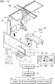
- FIG. 12 illustrates an example of displaying information about an X-ray detector 200 on an outer surface of the X-ray detector 200.
- the X-ray detector 200 may have a plurality of light sources 280 on an outer surface thereof.
- each of the plurality of light sources 280 may be composed of at least one of an LCD, an LED, and other light-emitting devices that output an optical signal.
- the plurality of light sources 280 may respectively output optical signals of different colors.
- the X-ray detector 200 may display a remaining battery capacity of the X-ray detector 200 by using the number of light sources from which optical signals are output among the plurality of light sources.
- the X-ray detector 200 may have five (5) light sources on its outer surface. When all of the five light sources in the X-ray detector 200 respectively output optical signals, a remaining battery capacity of the X-ray detector 200 may be 80 % to 100 %. When four of the light sources in the X-ray detector 200 output optical signals, the remaining battery capacity of the X-ray detector 200 may be 60 % to 80 %.
- the remaining battery capacity of the X-ray detector 200 may be 40 % to 60 %.
- the remaining battery capacity of the X-ray detector 200 may be 20 % to 40 %.
- the remaining battery capacity of the X-ray detector 200 may be 1 % to 20 %.
- Embodiments may be implemented through computer-readable recording media having stored thereon computer-executable instructions and data.
- the instructions may be stored in the form of program code, and when executed by a processor, generate a predetermined program module to perform a specific operation. Furthermore, when being executed by the processor, the instructions may perform specific operations according to the embodiments.
- a user of an X-ray imaging system including a plurality of X-ray imaging apparatuses may easily identify the X-ray imaging apparatus 100 into which the X-ray detector has been inserted. Furthermore, the user may easily activate the X-ray detector 200 inserted into the X-ray imaging apparatus 100 where an object P is placed. Then, the user may control X-rays to be emitted toward the X-ray imaging apparatus 100 where the object P is placed, thereby preventing emission of unnecessary X-rays onto the object P.
- An X-ray imaging apparatus may be implemented by mounting the X-ray detector 200 sensing interface (e.g., an optical sensor) and a display to an X-ray imaging apparatus of the related art.
- the X-ray detector 200 sensing interface e.g., an optical sensor
- a display e.g., a display
- the user of an X-ray imaging system including a plurality of X-ray imaging apparatuses may easily identify the X-ray imaging apparatus into which the X-ray detector 200 has been inserted.
Applications Claiming Priority (2)
| Application Number | Priority Date | Filing Date | Title |
|---|---|---|---|
| KR1020170131644A KR102444291B1 (ko) | 2017-10-11 | 2017-10-11 | 엑스선 영상 촬영 장치, 엑스선 디텍터 및 엑스선 영상 촬영 시스템 |
| PCT/KR2018/009377 WO2019074201A1 (ko) | 2017-10-11 | 2018-08-16 | 엑스선 영상 촬영 장치, 엑스선 디텍터 및 엑스선 영상 촬영 시스템 |
Publications (2)
| Publication Number | Publication Date |
|---|---|
| EP3659509A1 true EP3659509A1 (de) | 2020-06-03 |
| EP3659509A4 EP3659509A4 (de) | 2020-08-19 |
Family
ID=66100832
Family Applications (1)
| Application Number | Title | Priority Date | Filing Date |
|---|---|---|---|
| EP18866813.1A Withdrawn EP3659509A4 (de) | 2017-10-11 | 2018-08-16 | Röntgenbildgebungsvorrichtung, röntgendetektor und röntgenbildgebungssystem |
Country Status (4)
| Country | Link |
|---|---|
| US (1) | US10966673B2 (de) |
| EP (1) | EP3659509A4 (de) |
| KR (1) | KR102444291B1 (de) |
| WO (1) | WO2019074201A1 (de) |
Families Citing this family (3)
| Publication number | Priority date | Publication date | Assignee | Title |
|---|---|---|---|---|
| KR102444291B1 (ko) * | 2017-10-11 | 2022-09-16 | 삼성전자주식회사 | 엑스선 영상 촬영 장치, 엑스선 디텍터 및 엑스선 영상 촬영 시스템 |
| US11484281B2 (en) * | 2019-05-10 | 2022-11-01 | Konica Minolta, Inc. | Radiation image imaging apparatus, electronic device, wireless communication system, and storage medium |
| CN112190276B (zh) * | 2020-09-21 | 2024-02-27 | 上海联影医疗科技股份有限公司 | 探测系统及其探测方法 |
Family Cites Families (16)
| Publication number | Priority date | Publication date | Assignee | Title |
|---|---|---|---|---|
| US7154994B2 (en) * | 2004-04-14 | 2006-12-26 | Varian Medical Systems, Inc. | Synchronization of x-ray data acquisition |
| US7581885B2 (en) * | 2004-11-24 | 2009-09-01 | General Electric Company | Method and system of aligning x-ray detector for data acquisition |
| US7896547B2 (en) * | 2007-07-27 | 2011-03-01 | Fujifilm Corporation | Radiation image capturing system |
| US7983392B2 (en) * | 2008-11-12 | 2011-07-19 | Carestream Health, Inc. | Method for associating a wireless detector with an imaging apparatus |
| US8172461B2 (en) * | 2009-08-31 | 2012-05-08 | General Electric Company | Grid assembly positioning circuit and detector assembly including the same |
| JP5854580B2 (ja) * | 2009-11-24 | 2016-02-09 | キヤノン株式会社 | X線撮影装置及び制御方法 |
| US8744043B2 (en) * | 2010-01-05 | 2014-06-03 | Fujifilm Corporation | Radiation image capturing device and radiation image capturing system |
| US8243883B2 (en) * | 2010-05-07 | 2012-08-14 | General Electric Company | Wireless X-ray detector operation coordination system and method |
| US9405183B2 (en) * | 2010-05-12 | 2016-08-02 | Konica Minolta, Inc. | Radiation image capturing system |
| KR20150052769A (ko) * | 2013-11-06 | 2015-05-14 | 삼성전자주식회사 | 엑스선 디텍터, 엑스선 촬영 장치 및 그 제어 방법 |
| KR20150053697A (ko) * | 2013-11-08 | 2015-05-18 | 삼성전자주식회사 | 워크스테이션 및 엑스선 디텍터 |
| EP2870916B1 (de) * | 2013-11-08 | 2021-08-25 | Samsung Electronics Co., Ltd. | Medizinisches abbildungssystem und arbeitsstation und röntgendetektor dafür |
| WO2015080500A1 (en) * | 2013-11-28 | 2015-06-04 | Samsung Electronics Co., Ltd. | X-ray imaging apparatus and control method thereof |
| WO2017090969A1 (en) * | 2015-11-23 | 2017-06-01 | Samsung Electronics Co., Ltd. | X-ray detector, mobile device and host device |
| KR101893215B1 (ko) * | 2015-11-23 | 2018-08-29 | 삼성전자주식회사 | 엑스선 디텍터, 모바일 기기, 호스트 장치, 엑스선 영상 장치 및 엑스선 디텍터와 호스트 장치의 페어링 방법 |
| KR102444291B1 (ko) * | 2017-10-11 | 2022-09-16 | 삼성전자주식회사 | 엑스선 영상 촬영 장치, 엑스선 디텍터 및 엑스선 영상 촬영 시스템 |
-
2017
- 2017-10-11 KR KR1020170131644A patent/KR102444291B1/ko active IP Right Grant
-
2018
- 2018-08-16 EP EP18866813.1A patent/EP3659509A4/de not_active Withdrawn
- 2018-08-16 US US16/638,818 patent/US10966673B2/en active Active
- 2018-08-16 WO PCT/KR2018/009377 patent/WO2019074201A1/ko unknown
Also Published As
| Publication number | Publication date |
|---|---|
| KR102444291B1 (ko) | 2022-09-16 |
| US10966673B2 (en) | 2021-04-06 |
| WO2019074201A1 (ko) | 2019-04-18 |
| EP3659509A4 (de) | 2020-08-19 |
| KR20190040826A (ko) | 2019-04-19 |
| US20200187892A1 (en) | 2020-06-18 |
Similar Documents
| Publication | Publication Date | Title |
|---|---|---|
| EP2390682B1 (de) | Drahtloses Röntgendetektorbetriebskoordinationssystem und Verfahren | |
| US10966673B2 (en) | X-ray imaging device, x-ray detector, and x-ray imaging system | |
| US9610065B2 (en) | Probe control method and apparatus | |
| EP2974660B1 (de) | Röntgendetektor | |
| KR20150040768A (ko) | 엑스선 장치 및 엑스선 디텍터 | |
| US20140171799A1 (en) | Systems and methods for providing ultrasound probe location and image information | |
| CN107854133A (zh) | 将控制信号输出到医学成像装置的组件的方法和系统 | |
| US10004480B2 (en) | Probe control method and apparatus | |
| BE1020817A3 (nl) | Methode voor het identificeren van een direct digitaal radiografisch panel. | |
| CN109381209A (zh) | 放射线摄影系统及其工作方法 | |
| CN111954908A (zh) | 用于控制医学技术装置的运行的方法、操作设备、操作系统、医学技术装置、计算机程序和电子可读的数据载体 | |
| US10853450B2 (en) | Radiographing apparatus, radiographing system, radiographing method, and program | |
| US20150379217A1 (en) | Medical information display system, server, and portable terminal | |
| US10624603B2 (en) | X-ray input apparatus, x-ray imaging apparatus including the same, and method of controlling the x-ray input apparatus | |
| US20170083671A1 (en) | Apparatus for maintenance support in medical technology devices | |
| US10281599B2 (en) | X-ray apparatus and method of operating the same | |
| KR102272055B1 (ko) | 엑스선 입력 장치, 이를 포함하는 엑스선 영상 장치 및 엑스선 입력 장치의 제어 방법 | |
| US20180199909A1 (en) | X-ray detector, x-ray imaging device, and control method therefor | |
| JP2015191555A (ja) | 携帯型コンソール、携帯型コンソールの制御方法、携帯型コンソールの制御プログラム、及び撮影スキル分析システム | |
| EP2889000B1 (de) | Verfahren und Vorrichtung zum Speichern von Röntgenstrahlendaten in einem Röntgenstrahldetektionsmodul | |
| CN105431087A (zh) | 用于在多站射线照相曝光室中检测便携式直接射线照相板的方法和系统 | |
| EP3646043B1 (de) | Tragbare vorrichtung zur überwachung eines patienten und erkennen einer störungsquelle | |
| KR20130039451A (ko) | 엑스레이 시스템을 위한 디지털 의료영상 시스템 및 장치 |
Legal Events
| Date | Code | Title | Description |
|---|---|---|---|
| STAA | Information on the status of an ep patent application or granted ep patent |
Free format text: STATUS: THE INTERNATIONAL PUBLICATION HAS BEEN MADE |
|
| PUAI | Public reference made under article 153(3) epc to a published international application that has entered the european phase |
Free format text: ORIGINAL CODE: 0009012 |
|
| STAA | Information on the status of an ep patent application or granted ep patent |
Free format text: STATUS: REQUEST FOR EXAMINATION WAS MADE |
|
| 17P | Request for examination filed |
Effective date: 20200225 |
|
| AK | Designated contracting states |
Kind code of ref document: A1 Designated state(s): AL AT BE BG CH CY CZ DE DK EE ES FI FR GB GR HR HU IE IS IT LI LT LU LV MC MK MT NL NO PL PT RO RS SE SI SK SM TR |
|
| AX | Request for extension of the european patent |
Extension state: BA ME |
|
| A4 | Supplementary search report drawn up and despatched |
Effective date: 20200722 |
|
| RIC1 | Information provided on ipc code assigned before grant |
Ipc: A61B 6/00 20060101AFI20200716BHEP |
|
| DAV | Request for validation of the european patent (deleted) | ||
| DAX | Request for extension of the european patent (deleted) | ||
| GRAP | Despatch of communication of intention to grant a patent |
Free format text: ORIGINAL CODE: EPIDOSNIGR1 |
|
| STAA | Information on the status of an ep patent application or granted ep patent |
Free format text: STATUS: GRANT OF PATENT IS INTENDED |
|
| INTG | Intention to grant announced |
Effective date: 20230209 |
|
| STAA | Information on the status of an ep patent application or granted ep patent |
Free format text: STATUS: THE APPLICATION IS DEEMED TO BE WITHDRAWN |
|
| 18D | Application deemed to be withdrawn |
Effective date: 20230620 |