EP3659462A1 - Luggage with a recessed zipper - Google Patents
Luggage with a recessed zipper Download PDFInfo
- Publication number
- EP3659462A1 EP3659462A1 EP19199261.9A EP19199261A EP3659462A1 EP 3659462 A1 EP3659462 A1 EP 3659462A1 EP 19199261 A EP19199261 A EP 19199261A EP 3659462 A1 EP3659462 A1 EP 3659462A1
- Authority
- EP
- European Patent Office
- Prior art keywords
- zipper
- luggage piece
- recessed area
- lid
- base
- Prior art date
- Legal status (The legal status is an assumption and is not a legal conclusion. Google has not performed a legal analysis and makes no representation as to the accuracy of the status listed.)
- Granted
Links
Images












Classifications
-
- A—HUMAN NECESSITIES
- A45—HAND OR TRAVELLING ARTICLES
- A45C—PURSES; LUGGAGE; HAND CARRIED BAGS
- A45C5/00—Rigid or semi-rigid luggage
- A45C5/02—Materials therefor
-
- A—HUMAN NECESSITIES
- A45—HAND OR TRAVELLING ARTICLES
- A45C—PURSES; LUGGAGE; HAND CARRIED BAGS
- A45C5/00—Rigid or semi-rigid luggage
- A45C5/03—Suitcases
-
- A—HUMAN NECESSITIES
- A45—HAND OR TRAVELLING ARTICLES
- A45C—PURSES; LUGGAGE; HAND CARRIED BAGS
- A45C5/00—Rigid or semi-rigid luggage
- A45C5/04—Trunks; Travelling baskets
-
- A—HUMAN NECESSITIES
- A45—HAND OR TRAVELLING ARTICLES
- A45C—PURSES; LUGGAGE; HAND CARRIED BAGS
- A45C13/00—Details; Accessories
- A45C13/10—Arrangement of fasteners
- A45C13/1023—Arrangement of fasteners with elongated profiles fastened by sliders
- A45C13/103—Arrangement of zip-fasteners
-
- A—HUMAN NECESSITIES
- A45—HAND OR TRAVELLING ARTICLES
- A45C—PURSES; LUGGAGE; HAND CARRIED BAGS
- A45C13/00—Details; Accessories
- A45C13/26—Special adaptations of handles
-
- A—HUMAN NECESSITIES
- A45—HAND OR TRAVELLING ARTICLES
- A45C—PURSES; LUGGAGE; HAND CARRIED BAGS
- A45C13/00—Details; Accessories
- A45C13/36—Reinforcements for edges, corners, or other parts
-
- A—HUMAN NECESSITIES
- A45—HAND OR TRAVELLING ARTICLES
- A45C—PURSES; LUGGAGE; HAND CARRIED BAGS
- A45C5/00—Rigid or semi-rigid luggage
- A45C5/14—Rigid or semi-rigid luggage with built-in rolling means
-
- A—HUMAN NECESSITIES
- A45—HAND OR TRAVELLING ARTICLES
- A45C—PURSES; LUGGAGE; HAND CARRIED BAGS
- A45C5/00—Rigid or semi-rigid luggage
-
- A—HUMAN NECESSITIES
- A45—HAND OR TRAVELLING ARTICLES
- A45C—PURSES; LUGGAGE; HAND CARRIED BAGS
- A45C7/00—Collapsible or extensible purses, luggage, bags or the like
- A45C7/0018—Rigid or semi-rigid luggage
- A45C7/0022—Rigid or semi-rigid luggage comprising an integrated expansion device
Definitions
- the technological field generally relates to luggage.
- Zippers are often provided on luggage to access luggage compartments.
- Each zipper typically includes a zipper track, a zipper slider, and a zip pull tab.
- the zipper track is typically positioned approximately flush with an outer surface of the luggage.
- the zipper slider usually projects outwardly from the outer surface of the luggage. This outward projection also makes the zipper slider vulnerable to being damaged.
- One embodiment of a luggage piece may include at least six sides defining an enclosed space and a zipper positioned along at least one side of the at least six sides.
- the zipper and the at least one side may be configured so that the zipper provides access to the enclosed space.
- the zipper may include a zipper track.
- a first segment of the zipper track may be recessed relative to an outermost surface of the at least one side.
- a second segment of the zipper track may be positioned at approximately the outermost surface of the at least one side.
- a luggage piece may include a front side, a rear side, a right side, a left side, a top side, and a bottom side.
- the front, rear, right, left, top, and bottom sides may define an enclosed space.
- a zipper may be positioned along at least portions of the right, left, top, and bottom sides.
- the zipper and the right, left, top, and bottom sides may be configured so that the zipper provides access to the enclosed space.
- the zipper may include a zipper track.
- a first segment of the zipper track may be recessed relative to an outermost surface of the top side, and a second segment of the zipper track may be positioned at approximately the outermost surface of the top side.
- a luggage piece may include a base, a lid and a zipper.
- the lid may be pivotally joined to the base to pivot between at least a first position where the base and the lid define a substantially enclosed space and a second position to allow access to the substantially enclosed space.
- the lid and the base together may define an area recessed relative to outermost surfaces of the lid and the base when the lid and the base are configured in the first position.
- the zipper may maintain the lid and the base in the first position.
- the zipper may be joined to the lid and the base at least within the recessed area.
- a luggage piece may include a base, a lid, and a zipper.
- the lid may be pivotally joined to the base to pivot between at least a first position where the base and the lid define a substantially enclosed space and a second position to allow access to the substantially enclosed space.
- the zipper may be configured in a first configuration to secure the lid and the base in the first position and in a second configuration to allow the lid and the base to be selectively moved between the first and second positions.
- the base may include a first shell that defines at least a first outer portion of the base.
- the lid may include a second shell that defines at least a first outer portion of the lid.
- a first segment of the zipper may be joined to the first and second shells on inner facing surfaces of the first and second shells. The thicknesses of the first and second shells may be sufficiently large so that at least along the first segment of the zipper, a portion of the zipper is recessed relative to the outermost portions of the first and second shells that are proximate the zipper.
- Still another embodiment of the luggage piece may include a base, a lid, and a zipper.
- the lid may be pivotally joined to the base to pivot between at least a first position where the base and the lid define a substantially enclosed space and a second position to allow access to the substantially enclosed space.
- the zipper may be configured in a first configuration to secure the lid and the base in the first position and in a second configuration to allow the lid and the base to be selectively moved between the first and second positions.
- the base may include a first outer member that defines at least an outer portion of the base.
- the lid may include a second outer member that defines at least an outer portion of the lid.
- a first support member may be joined to an inner facing surface of the first outer member. The first support member may be located between the first outer member and a segment of the zipper.
- a second support member may be joined to an inner facing surface of the second outer member.
- the second support member may be located between the second outer member and the segment of the zipper.
- a combined thickness of the first support member and the first outer member and a combined thickness of the second support member and the second outer member may both be sufficiently large so that along the segment of the zipper, a portion of the zipper is recessed relative to the outermost portions of the first and second outer members that are proximate to the zipper.
- a luggage piece may include a base, a lid, a zipper, and a carry handle.
- the lid may be pivotally joined to the base to pivot between at least a first position where the base and the lid define a substantially enclosed space and a second position to allow access to the substantially enclosed space.
- the zipper may be configurable in a first configuration to secure the lid and the base in the first position and in a second configuration to allow the lid and the base to be selectively moved between the first and second positions.
- the carry handle may be joined to the lid and the base.
- a luggage piece may include a base, a lid, and a carry handle.
- the lid may be pivotally joined to the base by a hinge to pivot between at least a first position where the base and the lid define a substantially enclosed space and a second position to allow access to the substantially enclosed space.
- the carry handle may be joined to the lid, the base, and the hinge.
- a further embodiment of a luggage piece may include a base, a lid, and a carry handle.
- the lid may be pivotally joined to the base to pivot between at least a first position where the base and the lid define a substantially enclosed space and a second position to allow access to the substantially enclosed space.
- the carry handle may be joined to the lid and the base, and the carry handle may be positioned proximate abutting edges of the lid and the base.
- Such a luggage piece may include a front side, a rear side, a top side, a bottom side, a right side and a left side that define an enclosed space.
- the enclosed space may be divided into one or more compartments.
- the luggage piece may further include at least one zipper to access the enclosed space.
- the at least one zipper may include a zipper track, at least one zipper slider, and at least one zipper tab. At least a portion of the zipper track may be positioned within one or more recessed areas defined by at least some of the sides of the luggage or may be otherwise configured relative to other components of the luggage piece to be at least partially recessed relative to an outer surface of the luggage piece.
- the zipper track may be recessed relative to an outer surface of the luggage piece along substantially the entire length of the zipper track.
- Fig. 1 shows a front perspective view of one example of a luggage piece 100 that utilizes a recessed zipper
- Fig. 2 shows a rear perspective view of the luggage piece 100 shown in Fig. 1
- the luggage piece 100 may include a front side 105, a rear side 110, a top side 115, a bottom side 120, a right side 125 and a left side 130 that define an enclosed space (not shown).
- the enclosed space may be divided into one or more compartments.
- the luggage piece 100 may further include one or more wheels 135 joined to the bottom side 120 of the luggage piece 100.
- the wheels 135 may be spinner wheels, as shown in Fig. 1 , or fixed direction wheels.
- the luggage piece 100 may have more or less than four wheels.
- one or more foots or other supports may be joined to the bottom side of the luggage piece to facilitate positioning and maintaining the luggage piece in an upright position, similar to the upright position for the luggage piece 100 shown in Figs. 1 and 2 .
- the luggage piece 100 may further including one or more handles. At least one of the handles may be a telescoping handle 140 that may be selectively positioned between a retracted position and one or more extended positions. In an extended position, the telescoping handle 140 may be used to facilitate using the wheels 135 to push or pull the luggage piece 100 along a support surface.
- One or more of the handles may be carry handles 145. In Fig. 1 , two carry handles 145 are shown: one joined to top side 115 of the luggage piece 100, and the other to the right side 125 of the luggage piece 100. The carry handles 145 may be used to lift or carrying the luggage piece 100. Of course, more or less than two carry handles 145 could be joined to the luggage piece 100.
- the luggage piece 100 may further include a first zipper 150 that provides access to the enclosed space. More particularly, the front side 105 and portions of the right, left, top, and bottom sides 125, 130, 115, 120 of the luggage piece 100 may be joined to define a first luggage portion 155, or first shell portion, of the luggage piece 100 that can move in unison. Similarly, the rear side 110 and remaining portions of the right, left, top, and bottom sides 125, 130, 115, 120 of the luggage piece 100 may define a second luggage portion 160, or second shell portion, of the luggage piece 100 that move in unison.
- the first luggage portion 155 may also be referred to as a lid or base
- the second luggage portion 160 may be referred to as a base (when the first luggage portion 155 is considered to be lid) or lid (when the first luggage portion 155 is considered to be a base).
- the first and second luggage portions 155, 160 may be joined by a hinge 165 that allows them to be selectively pivoted relative to each other to different configurations while remaining joined via the hinge 165. In the configuration shown in Fig. 1 , the first and second luggage portions 155, 160 collectively define the enclosed spaced. When pivoted to other positions where the abutting edges of first and second luggage portions 155, 160 are separated, the enclosed space may be accessed.
- the first zipper 150 may be positioned along the abutting edges of the first and second luggage portions 155, 160.
- the first zipper 150 may include a zipper track 170, two zipper sliders 175, and two zipper tabs 180. Each zipper tab 180 may be joined to a respective zipper slider 175 to facilitate selectively moving its respective zipper slider 175 along the zipper track 170.
- the zipper track 170 may be positioned along the abutting edges of the first and second luggage portions 155, 160 from at least one end portion of the hinge 165 to the distal end portion of the hinge 165.
- the zipper track 170 may extend from at least an upper end portion 185 of the hinge 165 to the top side 115 of the luggage piece 100, along the top side 115 of the luggage piece 100 to the right side 125 of the luggage piece 100, along the right side 125 of the luggage piece 100 to the bottom side 120 of the luggage piece 100, along the bottom side 120 of the luggage piece 100 to the left side 130 of the luggage piece 100, and along the left side 130 of the luggage piece 100 to at least a lower end portion 190 of the hinge 165.
- the zipper track 170 may include a first set of teeth 195 joined to a first zipper tape 205 and a second set of teeth 200 joined to a second zipper tape 210.
- the first set of teeth 195 may be joined to the edge 215 of the first luggage portion 155 that abuts the second luggage portion 160
- the second set of teeth 200 may be joined to the edge 220 of the second luggage portion 160 that abuts the first luggage portion 155.
- the first and second sets of teeth 195, 200 may be joined to the first and second luggage portions 155, 160, respectively, by any suitable connection method, including, but not limited to, by sewing, bonding, adhering, welding, and so on.
- the teeth of first set of teeth 195 may be configured to selectively engage corresponding teeth on the second set of teeth 200. Selectively moving the zipper sliders 175 along the zipper track 170 causes the teeth of the first and second sets of teeth 195, 200 to be selectively engaged and disengaged. When one or both of the zipper sliders 175 are moved away from each other, at least some of the teeth in the first and second sets of teeth 195, 200 are disengaged, thus creating an opening in the zipper track 170. When a sufficient number of teeth in the first and second sets of teeth 195, 200 are disengaged, the opening is sufficiently large to allow access to the enclosed space defined by the first and second luggage portions 155, 160.
- the first luggage portion 155 may be selectively pivoted relative to the second luggage portion 160, or vice versa.
- the first and second luggage portions 155, 160 cannot be selectively pivoted relative to each other.
- the first zipper 150 may only include one zipper slider 175.
- the first zipper 150 includes a single zipper slider 175, moving the zipper slider 175 in one direction engages the teeth of the first and second sets of teeth 195, 200 and moving the zipper slider 175 in the opposite direction disengages the teeth.
- the single zipper slider 175 is positioned at one end of the zipper track 170, substantially all of the teeth in the first and second sets of teeth 195, 200 are disengaged, and when the single zipper slider 175 is positioned at the other end of the zipper track 170, substantially all of the teeth for the first and second sets of teeth 195, 200 are engaged.
- the first zipper 150 with a single zipper slider 175 operates in a similar manner as a first zipper 150 with two zipper sliders 175. Specifically, when all teeth of the first and second sets of teeth 195, 200 are engaged, access to the enclosed space is prevented. When a sufficient number of teeth of the first and second sets of teeth 195, 200 are disengaged, the enclosed space may be accessed. When substantially all of the teeth of the first and second sets of teeth 195, 200 are disengaged, the first and second luggage portions 155, 160 may be selectively pivoted relative to each other.
- the zipper track 170 may be recessed relative to the outer surfaces of the first and second luggage portions 155, 160. In some embodiments, the zipper track 170 may be recessed along one or more portions or segments of the zipper track's length. In other embodiments, the zipper track 170 may be recessed along the entire length of the zipper track 170.
- Figs. 1-15 show various embodiments of the luggage piece 100 in which the zipper track 170 is recessed along only portions or segments of the zipper track's length.
- the zipper track 170 may be recessed along the right and left sides 125, 130 of the luggage piece 100 by positioning the zipper track 170 within recessed areas defined by the right and left sides 125, 130 of the luggage piece 100.
- the recessed area defined by the outer facing surface of the luggage piece 100 tapers.
- the zipper track 170 may be positioned at or near the outermost surface 225 of the top side 115 of the luggage piece 100.
- the zipper track 170 may be maintained at this position relative to the outermost surface 225 of the top side 115 of the luggage piece 100 until the zipper track 170 nears the left side 130 of the luggage piece 100.
- outer facing surface of the top side 115 of the luggage piece 100 begins to taper inward to define a recessed area relative to the outermost surface 225 of the top side 115.
- the location of the change from the recessed to the non-recessed portions, or segments may depend, at least in part, on how the luggage piece 100 is constructed.
- the luggage piece 100 shown in Figs. 1-15 depicts a hybrid construction that includes components of a relatively rigid, semi-rigid, hard, or semi-hard material (collectively "harder material”) and a relatively soft or non-rigid material (collectively "softer material").
- the right and left sides 125, 130 of the luggage piece 100 along with portions of the front, rear, top, and bottom sides 105, 110, 115, 120 of the luggage piece 100 adjacent the right and left sides 125, 130 may be formed using a harder material, such as acrylonitrile-butadiene-styrene ("ABS") plastic, polycarbonate plastic, an ABS/polycarbonate plastic blend, and so on.
- ABS acrylonitrile-butadiene-styrene
- the harder areas may define four corner columns or supports for the luggage piece 100.
- the remaining or central portions of the front, rear, top, and bottom sides 105, 110, 115, 120 may be formed using a softer material, such as fabric or the like.
- one or more support members such as curved polypropylene (“PP”) or polyethylene (“PE”) sheets, may be provided at the top and bottom sides 115, 120 of the luggage piece 100 to help to maintain the shape of the luggage piece 100 in these regions.
- PP polypropylene
- PE polyethylene
- the harder areas are shown as vertical columns, these areas could be formed as horizontal columns positioned at the top and bottom sides 115, 120 of the luggage piece 100.
- the harder areas would generally include the top and bottom sides 115 120 of the luggage piece 100 along with portions of the front rear, right, and left sides 105, 110, 125, 130 of the luggage piece 100.
- the remaining portions of the front, rear, right, and left sides 105, 110, 125, 130 may be formed using a relatively soft or pliable material, with support material also provided, as needed.
- the harder and softer materials forming the sides 105, 110, 115, 120, 125, 130 of the luggage piece 100 may be joined by any suitable method, including, but not limited to, by stitching, bonding, welding or adhering the materials at their abutting edges. Proximate, or at the location, of the transition from the harder region to the softer region, the recess relative to the outermost surfaces of the sides 105, 110, 115, 120, 125, 130 may end so that at, or near, this transition, the zipper track 170 ceases to be recessed relative to the outermost surfaces of the sides 105, 110, 115, 120, 125, 130 of the luggage piece 100.
- the zipper track 170 may be recessed along the right side 125 of the luggage piece 100 by defining a recessed area within the right side 125 of the luggage piece 100.
- the right side 125 of the luggage piece 100 may be formed to define a pair of recessed area sidewalls 230a-b that extend from the outermost surfaces 235a-b of the right side 125 of the luggage piece 100 toward the enclosed space defined by the first and second luggage portions 155, 160.
- the end portion of the recessed area sidewalls 230a-b proximate respective outermost surfaces 235a-b of the right side 125 of the luggage piece 100 may be referred to herein as the outer recessed area sidewall end portion, and the end portion of the sidewall distal this outer sidewall end portion may be referred to herein as the inner recessed area sidewall end portion.
- One of the recessed area sidewalls 230a may be positioned on the first luggage portion 155, and the other recessed area sidewall 230b may be positioned on the second luggage portion 160.
- Each recessed area sidewall 230a-b may extend transversely, or approximately transversely, from its respective outermost surfaces 235a-b on the first and second luggage portions 155, 160. If desired, either of the recessed area sidewalls 230a-b may extend away from its respective outermost surface 235a-b at an angle.
- Each recessed area sidewall 230a-b may be spaced apart from the other recessed sidewall 230a-b at least a sufficient distance along the lengths of the recessed area sidewalls 230a-b to accommodate the width of the zipper track 170.
- the outer facing surface of each recessed area sidewall 230a-b may be generally parallel to the outer facing surface of the other recessed area sidewall 230a-b along the lengths of the recessed area sidewalls 230a-b.
- a recessed area flange 240a-b may extend from each recessed area sidewall 230a-b proximate the inner recessed area sidewall end portion of its respective recessed area sidewall 230a-b.
- Each recessed area flange 240a-b may extend generally transversely, or approximately transversely, from its respective recessed area sidewall 230a-b towards the other recessed area sidewall 230a-b.
- each recessed area flange 240a-b may end proximate the recessed area flange 240a-b extending from the other recessed area sidewall 230a-b such that the free ends of the recessed area flanges 240a-b abut each other.
- the zipper track 170 may be joined to the recessed area flanges 240a-b.
- the first set of the teeth 195 for the zipper track 170 may be joined to one of the recessed area flanges 240a
- the second set of teeth 200 for the zipper track 170 may be joined to the other recessed area flange 240b.
- the first and second sets of teeth 195, 200 for the zipper track 170 may be joined by any suitable connection method, including, but not limited to, by stitching, bonding, fastening, welding, or adhering the first and second sets of zipper teeth 195, 200 to their respective flanges 240a-b.
- the location of the recessed area flanges 240a-b relative to the outermost surface 235 of the right side 125 of the luggage piece 100 defines the depth that the zipper track 170 is recessed relative to the outermost surface 235 of the right side 125 of the luggage piece 100. Further, this depth may be selected such that no portion of the zipper sliders 175 extend beyond the outermost surface 235 of the right side 125. In some embodiments, however, the depth may be designed such that at least a portion, usually an upper portion, of the zipper sliders 175 extend beyond the outermost surface 235 of the right side 125.
- the depth of the recessed area may be varied along the top, bottom, right or left sides 115, 120, 125, 130 and/or in the area where the luggage piece 100 transitions from the right and left sides 125, 130 to the top and bottom sides 115, 120.
- the depth is varied by tapering the recessed area until the recessed area ceases to exist. Such a tapering may be linear or non-linear. Various means could be used to accomplish this tapering.
- this tapering may be implemented by reducing the distance from the outer recessed area sidewall end portion to the inner recessed area sidewall end portion along the length of the recessed area sidewalls 230a-b. By reducing this distance, the distance of the recessed area flanges 240a-b from the outermost surface of a respective side 115, 120, 125, 130 is reduced, thus reducing the depth of the recessed area.
- the tapering of the recessed area may be accomplished by increasing the thickness of the recessed area flanges 240a-b along the lengths of their respective recessed area sidewalls 230a-b such the outer facing surface of the recessed area flanges 240a-b are positioned closer to the outermost surface of a respective side 115, 120, 125, 130 along the lengths of their respective recessed area sidewalls 230a-b.
- the outer facing surface of the recessed area flanges 240a-b defines the effective depth of the recessed area, positioning their outer facing surfaces closer to the outermost surface of a respective side 115, 120, 125, 130 along the lengths of their respective recessed area sidewalls 230a-b decreases the depth of the recessed area.
- a similar result could be achieved by maintaining the thickness of the recessed area flanges 240a-b while gradually changing the location of the recessed area flanges 240a-b from the inner recessed area sidewall end portion to the outer recessed area sidewall end portion of their respective recessed area sidewalls 230a-b along the lengths of the recessed area sidewalls 230a-b.
- the zipper track 170 may be joined to the luggage piece 100 proximate the outermost surface of the side 105, 110,115, 120, 125, 130 of luggage piece 100 where the non-recessed portion of the zipper track 170 is located.
- the zipper track 170 on the top side 115 of the luggage piece 100 may be joined to an outer member 245, formed by a fabric or other suitable soft material, that defines the outermost surface 225 of the top side 115 of the luggage piece.
- a first support member 250 such as a sheet formed from polypropylene (“PP”), polyethylene (“PE”), or another suitable material, may be positioned under the outer member 245. Yet further, additional support may be provided by positioning a second support member 255, such as a wire or the like, under the first support member 250. To maintain the relative positions of the zipper track 170, the outer member 245, the first support member 250, and the second support member 255, these components may be joined together by stitching or any other suitable connection method.
- PP polypropylene
- PE polyethylene
- the second support member 255 may be wrapped in a cover 260 formed from a fabric material, a rubber material, a plastic material, or any other suitable material.
- a cover 260 formed from a fabric material, a rubber material, a plastic material, or any other suitable material.
- the zipper track 170 in non-recessed portions or segment may be joined to an outermost surface of a side 105, 110, 115, 120, 125, 130 of the luggage piece 100.
- the non-recessed portion of the zipper track 170 may be joined to a hard material, such as ABS plastic or the like.
- the zipper track 170 may be joined directly to the either the outer facing surface or the inner facing surface of such materials by any suitable connection method, including, but not limited to, by stitching, bonding, adhering, and welding.
- the second support member 255 such as a wire or the like, may be positioned under other components of the luggage piece 100 that support non-recessed portions or segments of the zipper track 170.
- the second support member 255 may also be positioned under components of the luggage piece 100 that are joined to the zipper track in recessed portions or segments of the zipper track 170.
- the second support member 255 may be positioned under the recessed area flanges 240a-b of the luggage piece 100 that are joined to the zipper track 170.
- the second support member 255 may be positioned proximate the recessed area sidewalls 230a-b of the harder material that define the recessed areas.
- the second support member 255 may be stitched, or otherwise suitably joined, to the harder material and the recessed zipper track 170 to maintain the relative position of these components to each other. To facilitate stitching or otherwise joining the second support member 255 to the harder material, the second support member 255 may be wrapped in the cover 260.
- a lining 265 and a binding 270 may also be joined to the zipper track 170, the outer member 245, the first support member 250, and the second support member 255.
- the lining 265 and the binding 270 may also be joined to the zipper track 170 and the harder material.
- the lining 265 and the binding 270 may be used to enhance the feel and/or the visual look of the luggage piece.
- the hinge 165 may be a fabric hinge, or any other suitable structure, that the joins the lid and the base in a hinged manner.
- the hinge 165 may be joined to the lid and the base by any suitable connection method, including, but not limited to, by stitching, adhering, bonding, or welding.
- the hinge 165 like the first zipper 150, may be recessed relative to the outermost surface of the luggage piece.
- the corner supports 275 for the luggage piece 100 may formed by a molding process.
- the corner supports 275 may be formed in a press mold 280 that generally defines the shape for two adjacent corner supports 275 using a male and female mold sections.
- the two adjacent corner supports 275 are joined together as shown in Fig. 12C .
- the molded material may be cut along the centerline of the recessed area, as shown in Fig. 12D .
- two of the four corner supports 275 are created for the luggage piece 100.
- the other two corner supports 275 may be formed using the same process. While the corner supports 275 are shown as being formed using a press mold 280, other types of molding, such as vacuum form molding may be used to form them.
- Figs. 17-25 show another embodiment of a luggage piece 300 with a recessed zipper, with like reference numbers used for elements of the second embodiment of the luggage piece 300 that are similar to elements of the first embodiment of the luggage piece 100.
- the luggage piece 300 is generally similar to the luggage piece shown in Fig. 1 except the zipper track 170 is recessed relative to the outermost surfaces of the sides 105, 110, 115, 120, 125, 130 of the luggage piece 300 along the length of the zipper track 170.
- the luggage piece also differs from the luggage piece shown in Fig. 1 in that the lid 155, which may also be referred to as the first luggage portion, and the base 160, which may also be referred to as the second luggage portion, are each formed of harder material joined by a piano-type hinge 165.
- the lid 155 and the base 160 may be formed to define a recessed area where the first zipper 150 is joined to these components. As described above, the first zipper 150 may be sewn, or joined by any other suitable connection method, to the lid 155 and the base 160.
- the luggage piece 300 is described as being formed from a hard material, the luggage piece 300 could be formed using a hybrid construction (e.g., using harder materials, such as plastic, for a portion of the outer surface and softer materials, such as fabric, for the remaining outer surface) or a soft material construction.
- the recessed areas for receiving the first zipper 150 may be formed by appropriately modifying support materials, such as the polypropylene or polyethylene sheets, to define the recessed areas.
- the first zipper 150 may be joined to the materials forming the lid 155 and the base 160 of the luggage piece 300 in such a manner that at least a portion of the first zipper 150 is recessed relative to the outermost surface of the sides of the luggage piece 300.
- the luggage piece 100 described above in connection with Figs. 1-15 could have exterior surfaces formed using either substantially all harder materials, such as plastic, or all softer materials, such as fabric.
- the harder materials could be molded or otherwise formed to define recessed and non-recessed areas for joining the first zipper 150 to the luggage piece 100, or the first zipper 150 may be joined to the components forming the lid 155 and the base 160 of the luggage piece 100 in such a manner that at least a portion of the first zipper 150 is recessed.
- the support elements for the softer material and/or the softer material could be formed to define recessed and non-recessed areas, or the first zipper 150 may be joined to the components forming the lid 155 and the base 160 of the luggage piece 100 in such a manner that at least a portion of the first zipper 150 is recessed.
- Figs. 26-33 show a third embodiment of a luggage piece 400 with a recessed zipper, with like reference numbers used for elements of the second embodiment of the luggage piece 400 that are similar to elements of the first and second embodiments of the luggage piece 100, 300.
- the third embodiment is similar to the first and second embodiments in that at least a portion of the first zipper 150 is recessed relative to respective outermost surfaces of the sides 105, 110, 115, 120, 125, 130 of the luggage piece 400 along at least a portion of the zipper track 170.
- the third embodiment of the luggage piece 400 differs from the first and second embodiments in that the first zipper 150 is recessed based on how it is positioned relative to the other components that define the lid 155, which may also be referred to as the first luggage portion, and base 160, which may also be referred to as the second luggage portion, of the luggage piece 400 rather than recessed by positioning the first zipper 150 within a recessed area defined by the hard material. Further, unlike the first embodiment, at least a portion of the first zipper 150 is recessed within an area of the luggage piece 400 formed by the softer material.
- the upper and lower portions of the third embodiment of the luggage piece 400 may be formed using a harder material, such as acrylonitrile-butadiene-styrene ("ABS") plastic, polycarbonate plastic, an ABS/polycarbonate plastic blend, and so on.
- ABS acrylonitrile-butadiene-styrene
- the remaining or central portions of the front, rear, right, and left sides 105, 110, 125 ,130 may be formed using a relatively soft or pliable material, such as fabric or the like.
- first support members 405 such as ABS plastic sheets or strips, may be provided at the right and left sides 125, 130 of the luggage piece proximate the first zipper 150 to help to maintain the shape of the luggage piece 400 in these regions and to also facilitate recessing at least a portion of the first zipper 150 relative to the outermost surfaces of the rights and left sides 125, 130 of the luggage piece 400.
- the harder materials defining the top and bottom portions of the luggage piece 400 may define the outer surface of the luggage piece 400 at these portions.
- a softer material such as an outer fabric or the like, may be joined to the outer facing surface of the upper and/or lower shells to enhance the look or the feel of the luggage piece 400.
- the upper shells 410 of the luggage piece 400 do not include a sidewall and a flange proximate the first zipper 150. Instead, a binding 270 may be joined by stitching or another suitable connection method to each upper shell 410 at a free end of the upper shell 410 where the zipper tape 205, 210 of the first zipper 150 are joined to the upper shells 410. Each zipper tape 205, 210 may then joined to an inner facing surface of one of the upper shells 410 by stitching or another suitable connection method.
- the first and second sets of zipper teeth 195, 200 of the first zipper 150 are positioned at approximately the same elevation as the inner surfaces of the upper shells 410.
- the zipper track 170 of the first zipper 150 is recessed relative to the outermost surface 225 of the top side 115 of the luggage piece 400, resulting in at least a portion of the first zipper 150 being recessed relative to the outermost surface 225 of the top side 115 of the luggage piece 400.
- the portion of the first zipper 150 recessed relative to the outermost surface 225 of the top side 115 of the luggage piece 400 is a function of the thickness of the upper shells 410 and the thickness of the bindings 270. As the combined thickness of the upper shells 410 and the bindings 270 increases, the portion of the first zipper 150 that is recessed relative to the outermost surface 225 of the top side 115 of the luggage piece 400 increases. In some embodiments, the combined thickness of the upper shells 410 and bindings 270 is sufficiently large that the entire first zipper 150 is recessed relative to the outermost surface 225 of the top side 115 of the luggage piece 400.
- the combined thickness of the upper shells 410 and bindings 270 may be selected so that a portion of the first zipper 150, usually an upper portion of the zipper slider 175, extends beyond the outermost surface 225 of the top side 115 of the luggage piece 400.
- the bindings 270 may be omitted.
- the amount of recess of the first zipper 150 relative to the outermost surface 225 of the top side 115 of the luggage piece 400 would be a function solely of the thicknesses of the upper shells 410.
- the entire first zipper 150, or a portion of the first zipper 150 may be recessed relative to the outermost surface 225 of the top side 115 of the luggage piece 400.
- the third embodiment of the luggage piece 400 may include second support members 255, such as wires or the like, to provide additional structural support to the upper shells 410 proximate the first zipper 150.
- each second support member 255 for the third embodiment of the luggage piece 400 may be placed in a cover 260 formed from a fabric, rubber or other suitable material to facilitate stitching or otherwise joining the second support member 255 to the first zipper 150 and a respective upper shell 410.
- the luggage piece 400 may further include interior zippers 415 that are positioned adjacent to the first zipper 150.
- Each interior zipper 415 may be joined to one of the second support member 255, the first zipper 150 and one of the upper shells 410 by stitching or another suitable connection method.
- Each interior zipper 415 may be used to selectively join and disconnect a lining 265 to one of the upper shells 410.
- the interior zippers 415 may be omitted, and the lining 265 may be relatively permanently joined to a respective first zipper 150, second support member 255, and upper shell 410 by stitching or another suitable connection method.
- each upper shell 410 may include a recessed area that is defined by a sidewall 420 and a flange 425 formed near a free end of the upper shell 410 that is the distal the free end that is joined to the first zipper 150.
- the outer member 245, which may formed from a fabric or other softer material, used in the softer areas of the luggage piece 400 may be joined by a suitable connection method (e.g., stitching) to an upper shell 410 proximate this recessed free end.
- the outer surfaces of the outer member 245 and the upper shell 410 can be positioned within approximately the same plane at the location of transition between the outer surfaces of the upper shell 410 and the outer member 245.
- Such recessing of the upper shells 410 also allows the respective outer members 245 to be folded upon themselves where they are joined to the upper shell 410 without it being visible from the outside of the luggage piece 400 that the outer members 245 thicker in these regions than in other regions.
- first zipper 150 and outer members 245 While the connection of the first zipper 150 and outer members 245 have been shown and described with reference to the upper shells 410 of the luggage piece 400, the first zipper 150 and outer member 245 may be joined to the lower shells of the luggage piece 400 in a similar manner. Further, the joining of the linings 265, interior zippers 415, and second support members 255, if any, to the lower shells may be done in a similar manner as described above and shown in Fig. 29 for the upper shells 410 of the luggage piece 400.
- the first zipper 150 may also be recessed within the softer regions of the luggage piece 400.
- the technique to recess the first zipper 150 is similar to the technique used in the harder regions except the upper and lower shells are replaced with the outer members 245, which define the outer surface of the luggage piece 400 in the softer regions, and first support members 405 that are positioned between the zipper tapes 205, 210 of the first zipper 150 and the inner surfaces of the outer members 245.
- the recess of the first zipper 150 relative to the outermost surface 430 of left side 130 of the luggage piece 400 is a function of the thickness of the bindings 270, the outer members 245, and the first support members 405.
- the combined thickness of the bindings 270, the outer members 245, and the first support members 405 increases, the portion of the first zipper 150 that is recessed relative to the outermost surface 430 of the left side 130 of the luggage piece 400 increases.
- the combined thickness of the bindings 270, the outer members 245, and the first support members 405 is sufficiently large that the entire first zipper 150 is recessed relative to the outermost surface 430 of the left side 130 of the luggage piece 400.
- the combined thickness of the bindings 270, the outer members 245, and the first support members 405 may be selected so that a portion of the first zipper 150, usually an upper portion of the zipper slider 170, extends beyond the outermost surface 430 of the left side 130 of the luggage piece 400.
- the bindings 270 and/or the first support members 405 may be omitted. In embodiments where only the bindings 270 are omitted, the amount of recess of the first zipper 150 would be a function of the thicknesses of the outer members 245 and the first support members 405. In embodiments where only the first support members 405 are omitted, the amount of recess of the first zipper 150 would be a function of the thickness of the outer members 245 and the bindings 270. In embodiments where both the bindings 270 and the first support members 405 are omitted, the amount of recess of the first zipper 150 would be a function of solely the thicknesses of the outer members 245. In any of these embodiments, the entire first zipper 150, or a portion of the first zipper 150, may be recessed relative to the outermost surface 430 of the left side 135 of the luggage piece 400.
- the first support members 405 may take the form of ABS sheets, strips, or the like. Each first support member 405 may be an elongated strap or the like with the length of the strap running substantially parallel to the longitudinal axis of the zipper track 170. Further, each first support member 405 may run from an upper shell 410 to a lower shell. Each first support member 405 may have a generally rectangular cross-section along the length of the first support member 405. The rectangular cross-section advantageously creates relatively planar surfaces that abut the binding 270 and inner surface of the outer member 245. While the cross-section along the length of the first support member 405 is described and shown as being rectangular, any other desired cross-sectional shape, including trapezoidal or circular, may be used for the first support member 405.
- one or more the following components may be joined to the outer members 245 and the first zipper 150 in the softer regions: second support members 255 to provide additional structural support, covers 260 to facilitate joining the second support members 255 to the other components, interior zippers 415 to selectively connect and disconnect linings 265 to the other components, and linings 265. As described above in connection with the harder region, these other components may be joined by any suitable method to the outer members 245 and the first zipper 150.
- the interior zippers 415 may be positioned next the first zipper 150, the first zipper 150 may be positioned next to the bindings 270, the bindings 270 may cover the free ends of the outer members 245 that are proximate the first zipper 150, and the first support members 405 may be positioned between the first zipper 150 and the inner surface of the outer members 245.
- the first zipper 150 may also be recessed in the softer region on the right side 125 of the luggage piece 400.
- the first zipper 150 may be recessed in a manner similar to the method used in the softer region on the left side 130 of the luggage piece 400. More particularly, the first zipper 150 may be joined on the inner surfaces of the outer members 245 with bindings 270 and first support members 405 positioned between the first zipper 150 and the outer members 245. Further, the amount of recess of the first zipper 150 relative to the outermost surface 235 of right side 125 of the luggage piece 400 may be a function of the thicknesses of the outer members 245 and one or more of the thicknesses of the bindings 270 and the first support members 405.
- one or more hinge members 435a-b may be joined to the outer members 245 that define the outer surfaces of the base 160 and the lid 155 of the luggage piece 400 in the softer region.
- the amount of recess of the first zipper 150 may further be a function of the thicknesses of the hinge members 435 a-b.
- the bindings 270 or the first support members 405 may be omitted.
- first hinge member 435a may be used to join the lid 155 and the base 160.
- first and second hinge members 435a-b may be used to join the lid 155 to the base 160, with the second or outer hinge member 435b covering the first or inner hinge member 435a.
- the hinge members 435a-b allow the lid 155 and the base 160 of the luggage piece 400 to be selectively pivoted relative to each other while keeping the lid 155 and the base 160 joined together when the first zipper 150 is moved to a position where a substantial portion of the teeth of the first and second sets of teeth 195, 200 are disengaged.
- the hinge members 435a-b made be formed from a flexible fabric or any other suitable material. Further, the hinge members 435a-b may be sewn or to the outer members 245 or joined by any other suitable connection method.
- one or more the following components may be joined to the outer members 245 and the first zipper 150 in the softer regions on the right side 125 of the luggage piece 400: second support members 255 to provide additional structural support, covers 260 to facilitate joining the second support members 255 to the other components, interior zippers 415 to selectively connect and disconnect linings 265 to the other components, and linings 265. As described above in connection with the harder region, these other components may be joined by any suitable method to the outer members 245 and the first zipper 150.
- the interior zippers 415 may be positioned next the first zipper 150, the first zipper 150 may be positioned next to the bindings 270, the bindings 270 may cover the free ends of the outer members 245 that are proximate the first zipper 150, and the first support members 405 may be positioned between the first zipper 150 and the inner surface of the outer members 245.
- a carry handle 145 may be joined to the luggage piece 400 on the hinged side of the luggage piece 400 in the softer region. Further, the carry handle 145 may be positioned so it is located above the first zipper 150 and so that the length of the carry handle 145 runs parallel to the zipper track 170. Such positioning of the carry handle 145 over the first zipper 150 allows for the carry handle 145 to be positioned at approximately the center of the luggage piece 400 on the hinged side of the luggage piece 400 when the lid 155 and the base 160 are approximately the same size. Thus, a longitudinal axis of the carry handle 145 may be aligned with a centerline of the luggage piece 400.
- the centerline of the luggage piece 400 may be a width centerline of the luggage piece 400. This may be beneficial in that it allows the carry handle 145 to be approximately aligned with the center or mass of the luggage piece 400 when the luggage piece 400 is moved using the carry handle 145.
- the carry handle 145 may be positioned above the first hinge member 435a and below the second hinge member 435b. Thus, within the middle portion of the luggage piece 400 on the hinged side, the carry handle 145 may be exposed for grasping by the user, while closer to the harder regions of the luggage piece 400, the carry handle 145 may be covered by the second hinge members 435b.
- the carry handle 145 may include an outer handle member 440.
- the outer handle member 440 may be formed using a webbed fabric or other suitable material that is durable, elastic and/or flexible.
- the outer handle member 440 may be configured to define a tubular shape.
- the carry handle 145 may further include an inner handle member 445 that is positioned within the tubular cavity defined by the outer handle member 440.
- the inner handle member 445 may be a foam (e.g., EVA foam), a gel or another resilient and soft material and may be formed using two or more pieces of the material.
- the inner handle member 445 generally provides the user with more comfortable grip when carrying the luggage piece 400 using the carry handle 145.
- the carry handle 145 may also include a biasing member 450 that is positioned with the tubular cavity defined by the outer handle member 440.
- the biasing member 450 may be configured to bias the carry handle 145 towards the outer surface of the luggage piece 400.
- the biasing member 450 may be one or more metal plates (e.g., steel plates) or other suitable structures that bias the carry handle 145 towards the outer surface of the luggage piece 400.
- Biasing the carry handle 145 towards the outer surface of the luggage piece 400 helps to reduce the dimensions of the luggage piece 400 when the carry handle 145 is not being used while allowing for the carry handle 145 to move away from the outer surface of the luggage piece 400 when grasped by a user in order to provide more space between the outer surface of the luggage piece 400 and the carry handle for the user's hands.
- the biasing member 450 may be positioned to be at least partially, up to fully, surrounded by the inner handle member 445. Such positioning of the biasing member 450 relative to the inner handle member 445 may reduce the ability of the user to feel the biasing member 450 within the outer handle member 440 and/or protect the user's hand from the biasing member 450.
- excess material that forms the outer handle member 440 may be placed within a cavity defined by the first and second hinge members 435a-b.
- the excess material allows for the total length of the carry handle 145 that is exposed outside of the second hinge members 435b to be selectively increased and decreased.
- the amount of space between the outer surface of the luggage piece 400 and the inward facing surface of the carry handle 145 increases, thus providing more room for a user's hand.
- the distance between the outer surface of the luggage piece 400 and the inward surface of the carry handle 145 decreases, thus bringing the carry handle 145 closer to the outer surface of the luggage piece 400.
- the biasing member 450 moves the carry handle 145 back towards the outer surface of the luggage piece 400.
- a rigid or semi-rigid handle support member 455 may be positioned within the cavity defined by the first and second hinge members 435a-b.
- the handle support member 455 may be positioned between the carry handle 145 and the second hinge member 435b.
- the handle support member 455 may be used to provide structural strength at the ends of the carry handle 145.
- the handle support member 455 may be made of a plastic material, such as polypropylene or polyethylene, or any other suitable material.
- the carry handle 145 may be joined to the first and second hinge members 435a-b and the outer members 245 by stitching or any other suitable connection method.
- the end portions of the outer handle member 440 may be stitched or otherwise joined to the first and second hinge members 435a-b and the outer members 245.
- Figs. 34 and 35 show a schematic partial top view of a fourth embodiment of a luggage piece 500 that incorporates a recessed zipper.
- the fourth embodiment of the luggage piece 500 is similar to the first embodiment of the luggage piece 100 except a second zipper 505 is positioned adjacent to the first zipper 150.
- the second zipper 505 may be used to selectively expand the size of the luggage piece 500.
- the front side 105 (or lid) of the luggage piece 500 may be moved away, in a transverse direction relative to the length of the second zipper 505, from the rear side 110 (or base) of the luggage piece.
- a gusset material 510 is exposed between the first and set sets of teeth 515, 520 of the second zipper 505.
- This gusset material 510 allows the lid 155 to be selectively moved away from the base 160 up to a predetermined distance. This capability to selectively move the lid 155 away from the base 160 allows for the area enclosed by the lid 155 and the base 160 to be selectively expanded.
- the second zipper 505 may be configured into its closed position.
- the first set of teeth 195 for the first zipper 150 may be joined to the lid 155 via the first tape
- the other set of teeth 200 for the first zipper 150 may be joined to a first set of teeth 515 for the second zipper 505 via zippers tapes associated with each set of teeth 200, 515.
- the second set of teeth 520 for the second zipper 505 may be joined to the base 160 via a zipper tape associated with the second set of teeth 520. If desired, the positions of the first and second zippers 150, 505 could be reversed. More particularly, the first zipper 150 could be positioned proximate the base 160, and the second zipper 505 could be positioned proximate the lid 155.
- the first and second zippers 150, 505 may be recessed in a similar manner as described above with respect to the first zipper 150 for the first, second or third embodiments of the luggage piece 100, 300, 400. Further, the first and second zippers 150, 505 may be recessed along portions or segments of their respective lengths, or may recessed along their entire lengths.
- end should be interpreted broadly, in a manner that includes areas adjacent, rearward, forward of, or otherwise near the terminus of a particular element, link, component, part, member or the like.
- steps and operations are described in one possible order of operation, but those skilled in the art will recognize that steps and operations may be rearranged, replaced, or eliminated without necessarily departing from the spirit and scope of the present invention.
Landscapes
- Chemical & Material Sciences (AREA)
- Engineering & Computer Science (AREA)
- Materials Engineering (AREA)
- Purses, Travelling Bags, Baskets, Or Suitcases (AREA)
Abstract
Description
- This application claims the benefit, under 35 U.S.C. § 119(e), of
U.S. provisional application number 61/408,346 - The technological field generally relates to luggage.
- Zippers are often provided on luggage to access luggage compartments. Each zipper typically includes a zipper track, a zipper slider, and a zip pull tab. For zippers positioned on the exterior of the luggage, the zipper track is typically positioned approximately flush with an outer surface of the luggage. Such a configuration makes the zipper track susceptible to being damaged from contact with other objects. Further, in such a configuration, the zipper slider usually projects outwardly from the outer surface of the luggage. This outward projection also makes the zipper slider vulnerable to being damaged.
- One embodiment of a luggage piece may include at least six sides defining an enclosed space and a zipper positioned along at least one side of the at least six sides. The zipper and the at least one side may be configured so that the zipper provides access to the enclosed space. The zipper may include a zipper track. A first segment of the zipper track may be recessed relative to an outermost surface of the at least one side. A second segment of the zipper track may be positioned at approximately the outermost surface of the at least one side.
- Another embodiment of a luggage piece may include a front side, a rear side, a right side, a left side, a top side, and a bottom side. The front, rear, right, left, top, and bottom sides may define an enclosed space. A zipper may be positioned along at least portions of the right, left, top, and bottom sides. The zipper and the right, left, top, and bottom sides may be configured so that the zipper provides access to the enclosed space. The zipper may include a zipper track. A first segment of the zipper track may be recessed relative to an outermost surface of the top side, and a second segment of the zipper track may be positioned at approximately the outermost surface of the top side.
- Yet another embodiment of a luggage piece may include a base, a lid and a zipper. The lid may be pivotally joined to the base to pivot between at least a first position where the base and the lid define a substantially enclosed space and a second position to allow access to the substantially enclosed space. The lid and the base together may define an area recessed relative to outermost surfaces of the lid and the base when the lid and the base are configured in the first position. The zipper may maintain the lid and the base in the first position. The zipper may be joined to the lid and the base at least within the recessed area.
- Another embodiment of a luggage piece may include a base, a lid, and a zipper. The lid may be pivotally joined to the base to pivot between at least a first position where the base and the lid define a substantially enclosed space and a second position to allow access to the substantially enclosed space. The zipper may be configured in a first configuration to secure the lid and the base in the first position and in a second configuration to allow the lid and the base to be selectively moved between the first and second positions. The base may include a first shell that defines at least a first outer portion of the base. The lid may include a second shell that defines at least a first outer portion of the lid. A first segment of the zipper may be joined to the first and second shells on inner facing surfaces of the first and second shells. The thicknesses of the first and second shells may be sufficiently large so that at least along the first segment of the zipper, a portion of the zipper is recessed relative to the outermost portions of the first and second shells that are proximate the zipper.
- Still another embodiment of the luggage piece may include a base, a lid, and a zipper. The lid may be pivotally joined to the base to pivot between at least a first position where the base and the lid define a substantially enclosed space and a second position to allow access to the substantially enclosed space. The zipper may be configured in a first configuration to secure the lid and the base in the first position and in a second configuration to allow the lid and the base to be selectively moved between the first and second positions. The base may include a first outer member that defines at least an outer portion of the base. The lid may include a second outer member that defines at least an outer portion of the lid. A first support member may be joined to an inner facing surface of the first outer member. The first support member may be located between the first outer member and a segment of the zipper. A second support member may be joined to an inner facing surface of the second outer member. The second support member may be located between the second outer member and the segment of the zipper. A combined thickness of the first support member and the first outer member and a combined thickness of the second support member and the second outer member may both be sufficiently large so that along the segment of the zipper, a portion of the zipper is recessed relative to the outermost portions of the first and second outer members that are proximate to the zipper.
- Another embodiment of a luggage piece may include a base, a lid, a zipper, and a carry handle. The lid may be pivotally joined to the base to pivot between at least a first position where the base and the lid define a substantially enclosed space and a second position to allow access to the substantially enclosed space. The zipper may be configurable in a first configuration to secure the lid and the base in the first position and in a second configuration to allow the lid and the base to be selectively moved between the first and second positions. The carry handle may be joined to the lid and the base.
- Yet another embodiment of a luggage piece may include a base, a lid, and a carry handle. The lid may be pivotally joined to the base by a hinge to pivot between at least a first position where the base and the lid define a substantially enclosed space and a second position to allow access to the substantially enclosed space. The carry handle may be joined to the lid, the base, and the hinge.
- A further embodiment of a luggage piece may include a base, a lid, and a carry handle. The lid may be pivotally joined to the base to pivot between at least a first position where the base and the lid define a substantially enclosed space and a second position to allow access to the substantially enclosed space. The carry handle may be joined to the lid and the base, and the carry handle may be positioned proximate abutting edges of the lid and the base.
-
-
Fig. 1 shows a perspective view of an embodiment of a luggage piece that incorporates a recessed zipper. -
Fig. 2 shows another perspective view of the luggage piece shown inFig. 1 -
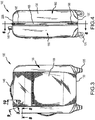
Fig. 3 shows a front elevation view of the luggage piece shown inFig 1 . -
Fig. 4 shows a side elevation view of the luggage piece shown inFig. 1 . -
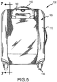
Fig. 5 shows a rear elevation view of the luggage piece shown inFig. 1 . -
Fig. 6 shows a cross-section view of the luggage piece shown inFig 1 , viewed along line 6-6 inFig. 4 . -
Fig. 7 shows a cross-section view of the luggage piece shown inFig 1 , viewed along line 7-7 inFig. 5 . -
Fig. 8 shows a partial cross-section view of the luggage piece shown inFig. 1 , viewed along line 8-8 inFig. 3 . -
Fig. 9 shows a partial cross-section view of the luggage piece shown inFig. 1 , viewed along line 9-9 inFig. 3 . -
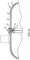
Fig. 10 shows a partial cross-section view of the luggage piece shown inFig. 1 , viewed along line 10-10 inFig. 3 . -
Fig. 11 shows an exploded view of some of the components that form the luggage piece shown inFig. (1 . -
Fig. 12 shows a partial cross-section view of the luggage piece shown inFig. 1 that is similar to the view shown inFig. 7 except this view shows another way to join various components of the luggage piece together. -
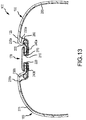
Fig. 13 shows a partial cross-section view of the luggage piece shown inFig. 1 that is similar to the view shown inFig. 8 except this view shows another way to join various components of the luggage piece together. -
Fig. 14 shows a partial cross-section view of the luggage piece shown inFig. 1 that is similar to the view shown inFig. 9 except this view shows another way to join various components of the luggage piece together. -
Fig. 15 shows a partial cross-section view of the luggage piece shown inFig. 1 that is similar to the view shown inFig. 10 except this view shows another way to join various components of the luggage piece together. -
Figs. 16A-D show schematic views of one method to form the corner supports for the luggage piece shown inFig. 1 . -
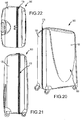
Fig. 17 shows a perspective view of a second embodiment of a luggage piece that incorporates a recessed zipper. -
Fig. 18 shows a bottom view of the luggage piece shown inFig. 17 . -
Fig. 19 shows a side view of the luggage piece shown inFig. 17 . -
Fig. 20 shows another perspective view of the of the luggage piece shown inFig. 17 . -
Fig. 21 shows another side view of the luggage piece shown inFig. 17 . -
Fig. 22 shows a top view of the luggage piece shown inFig. 17 . -
Fig. 23 shows a cross-section view of the luggage piece shown inFig. 17 , viewed along line 23-23 inFig. 19 . -
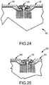
Fig. 24 shows a partial cross-section view of the luggage piece shown inFig. 17 , viewed along line 24-24 inFig. 23 . -
Fig. 25 shows a partial cross-section view of the luggage piece shown inFig. 17 , viewed along line 25-25 inFig. 23 . -
Fig. 26 shows a front perspective view of third embodiment of a luggage piece that incorporates a recessed zipper. -
Fig. 27 shows a front elevation view of the luggage piece ofFig. 26 . -
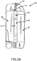
Fig. 28 shows a side elevation view of the luggage piece ofFig. 26 . -
Fig. 29 shows a cross-section view of the luggage piece ofFig. 26 , viewed along line 29-29 inFig. 27 . -
Fig. 30 shows a cross-section view of the luggage piece ofFig. 26 , viewed along line 30-30 inFig. 27 . -
Fig. 31 shows a cross-section view of the luggage piece ofFig. 26 , viewed along line 31-31 inFig. 27 . -
Fig. 32 shows a cross-section view of the luggage piece ofFig. 26 , viewed along line 32-32 inFig. 27 . -
Fig. 33 shows a cross-section view of the luggage piece ofFig. 26 , viewed along line 33-33 inFig. 28 . -
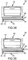
Fig. 34 shows a schematic partial top view of a fourth embodiment of a luggage piece that incorporates a recessed zipper and an expansion zipper, showing the expansion zipper in a closed position. -
Fig. 35 shows a schematic partial top view of the luggage piece ofFig. 34 , showing the expansion zipper in an open position. - Described herein are luggage pieces that incorporate at least one recessed zipper. Such a luggage piece may include a front side, a rear side, a top side, a bottom side, a right side and a left side that define an enclosed space. The enclosed space may be divided into one or more compartments. The luggage piece may further include at least one zipper to access the enclosed space. The at least one zipper may include a zipper track, at least one zipper slider, and at least one zipper tab. At least a portion of the zipper track may be positioned within one or more recessed areas defined by at least some of the sides of the luggage or may be otherwise configured relative to other components of the luggage piece to be at least partially recessed relative to an outer surface of the luggage piece. In some embodiments, the zipper track may be recessed relative to an outer surface of the luggage piece along substantially the entire length of the zipper track.
-
Fig. 1 shows a front perspective view of one example of aluggage piece 100 that utilizes a recessed zipper, andFig. 2 shows a rear perspective view of theluggage piece 100 shown inFig. 1 . With reference toFigs. 1 and 2 , theluggage piece 100 may include afront side 105, arear side 110, atop side 115, abottom side 120, aright side 125 and aleft side 130 that define an enclosed space (not shown). The enclosed space may be divided into one or more compartments. Theluggage piece 100 may further include one ormore wheels 135 joined to thebottom side 120 of theluggage piece 100. Thewheels 135 may be spinner wheels, as shown inFig. 1 , or fixed direction wheels. While fourspinner wheels 135 are shown in the figures, theluggage piece 100 may have more or less than four wheels. In embodiments that use two wheels, one or more foots or other supports may be joined to the bottom side of the luggage piece to facilitate positioning and maintaining the luggage piece in an upright position, similar to the upright position for theluggage piece 100 shown inFigs. 1 and 2 . - The
luggage piece 100 may further including one or more handles. At least one of the handles may be atelescoping handle 140 that may be selectively positioned between a retracted position and one or more extended positions. In an extended position, thetelescoping handle 140 may be used to facilitate using thewheels 135 to push or pull theluggage piece 100 along a support surface. One or more of the handles may be carry handles 145. InFig. 1 , two carryhandles 145 are shown: one joined totop side 115 of theluggage piece 100, and the other to theright side 125 of theluggage piece 100. The carry handles 145 may be used to lift or carrying theluggage piece 100. Of course, more or less than two carryhandles 145 could be joined to theluggage piece 100. - The
luggage piece 100 may further include afirst zipper 150 that provides access to the enclosed space. More particularly, thefront side 105 and portions of the right, left, top, andbottom sides luggage piece 100 may be joined to define afirst luggage portion 155, or first shell portion, of theluggage piece 100 that can move in unison. Similarly, therear side 110 and remaining portions of the right, left, top, andbottom sides luggage piece 100 may define asecond luggage portion 160, or second shell portion, of theluggage piece 100 that move in unison. Thefirst luggage portion 155 may also be referred to as a lid or base, and thesecond luggage portion 160 may be referred to as a base (when thefirst luggage portion 155 is considered to be lid) or lid (when thefirst luggage portion 155 is considered to be a base). The first andsecond luggage portions hinge 165 that allows them to be selectively pivoted relative to each other to different configurations while remaining joined via thehinge 165. In the configuration shown inFig. 1 , the first andsecond luggage portions second luggage portions - The
first zipper 150 may be positioned along the abutting edges of the first andsecond luggage portions first zipper 150 may include azipper track 170, twozipper sliders 175, and twozipper tabs 180. Eachzipper tab 180 may be joined to arespective zipper slider 175 to facilitate selectively moving itsrespective zipper slider 175 along thezipper track 170. Thezipper track 170 may be positioned along the abutting edges of the first andsecond luggage portions hinge 165 to the distal end portion of thehinge 165. For example, thezipper track 170 may extend from at least anupper end portion 185 of thehinge 165 to thetop side 115 of theluggage piece 100, along thetop side 115 of theluggage piece 100 to theright side 125 of theluggage piece 100, along theright side 125 of theluggage piece 100 to thebottom side 120 of theluggage piece 100, along thebottom side 120 of theluggage piece 100 to theleft side 130 of theluggage piece 100, and along theleft side 130 of theluggage piece 100 to at least alower end portion 190 of thehinge 165. - With reference to
Fig. 8 , thezipper track 170 may include a first set ofteeth 195 joined to afirst zipper tape 205 and a second set ofteeth 200 joined to asecond zipper tape 210. The first set ofteeth 195 may be joined to theedge 215 of thefirst luggage portion 155 that abuts thesecond luggage portion 160, and the second set ofteeth 200 may be joined to theedge 220 of thesecond luggage portion 160 that abuts thefirst luggage portion 155. The first and second sets ofteeth second luggage portions - The teeth of first set of
teeth 195 may be configured to selectively engage corresponding teeth on the second set ofteeth 200. Selectively moving thezipper sliders 175 along thezipper track 170 causes the teeth of the first and second sets ofteeth zipper sliders 175 are moved away from each other, at least some of the teeth in the first and second sets ofteeth zipper track 170. When a sufficient number of teeth in the first and second sets ofteeth second luggage portions teeth zipper track 170 are disengaged, thefirst luggage portion 155 may be selectively pivoted relative to thesecond luggage portion 160, or vice versa. Similarly, when a substantial majority of the teeth of the first and second sets ofteeth second luggage portions - While two
zipper sliders 175 are shown in the various figures to open and close theluggage piece 100, thefirst zipper 150 may only include onezipper slider 175. When thefirst zipper 150 includes asingle zipper slider 175, moving thezipper slider 175 in one direction engages the teeth of the first and second sets ofteeth zipper slider 175 in the opposite direction disengages the teeth. Thus, when thesingle zipper slider 175 is positioned at one end of thezipper track 170, substantially all of the teeth in the first and second sets ofteeth single zipper slider 175 is positioned at the other end of thezipper track 170, substantially all of the teeth for the first and second sets ofteeth first zipper 150 with asingle zipper slider 175 operates in a similar manner as afirst zipper 150 with twozipper sliders 175. Specifically, when all teeth of the first and second sets ofteeth teeth teeth second luggage portions - With reference to
Figs. 1-3 ,6-10 , and12-15 , at least a portion of thezipper track 170 may be recessed relative to the outer surfaces of the first andsecond luggage portions zipper track 170 may be recessed along one or more portions or segments of the zipper track's length. In other embodiments, thezipper track 170 may be recessed along the entire length of thezipper track 170. -
Figs. 1-15 show various embodiments of theluggage piece 100 in which thezipper track 170 is recessed along only portions or segments of the zipper track's length. With reference toFigs. 1, 2 and8 , thezipper track 170 may be recessed along the right and leftsides luggage piece 100 by positioning thezipper track 170 within recessed areas defined by the right and leftsides luggage piece 100. With reference toFigs. 8-10 and12-15 , as thezipper track 170 transitions from theright side 125 to thetop side 115 of theluggage piece 100, the recessed area defined by the outer facing surface of theluggage piece 100 tapers. This tapering continues until attop side 115 of theluggage piece 100, the outer facing surface of theluggage piece 100 ceases to define a recessed area. Near this location, thezipper track 170 may be positioned at or near theoutermost surface 225 of thetop side 115 of theluggage piece 100. Thezipper track 170 may be maintained at this position relative to theoutermost surface 225 of thetop side 115 of theluggage piece 100 until thezipper track 170 nears theleft side 130 of theluggage piece 100. As thezipper track 170 approaches theleft side 130 of theluggage piece 100, outer facing surface of thetop side 115 of theluggage piece 100 begins to taper inward to define a recessed area relative to theoutermost surface 225 of thetop side 115. This tapering continues until the full depth of the recessed area is defined along theleft side 130 of theluggage piece 100. A similar tapering of the recessed area occurs proximate the transition from the right and leftsides luggage piece 100 to thebottom side 120 of theluggage piece 100. Further, as with the positioning of thezipper track 170 on thetop side 115 of theluggage piece 100, at least a portion or segment of thezipper track 170 on thebottom side 120 of theluggage piece 100 may positioned at or near the outermost surface of thebottom side 120 of theluggage piece 100. - For embodiments where only portions or segments of the
zipper track 170 are recessed relative to the outermost surfaces of thesides luggage piece 100, the location of the change from the recessed to the non-recessed portions, or segments, may depend, at least in part, on how theluggage piece 100 is constructed. For example, theluggage piece 100 shown inFigs. 1-15 depicts a hybrid construction that includes components of a relatively rigid, semi-rigid, hard, or semi-hard material (collectively "harder material") and a relatively soft or non-rigid material (collectively "softer material"). Specifically, the right and leftsides luggage piece 100 along with portions of the front, rear, top, andbottom sides luggage piece 100 adjacent the right and leftsides luggage piece 100. The remaining or central portions of the front, rear, top, andbottom sides bottom sides luggage piece 100 to help to maintain the shape of theluggage piece 100 in these regions. - While the harder areas are shown as vertical columns, these areas could be formed as horizontal columns positioned at the top and
bottom sides luggage piece 100. In such a configuration, the harder areas would generally include the top andbottom sides 115 120 of theluggage piece 100 along with portions of the front rear, right, and leftsides luggage piece 100. Like the vertical column embodiment, the remaining portions of the front, rear, right, and leftsides - The harder and softer materials forming the
sides luggage piece 100 may be joined by any suitable method, including, but not limited to, by stitching, bonding, welding or adhering the materials at their abutting edges. Proximate, or at the location, of the transition from the harder region to the softer region, the recess relative to the outermost surfaces of thesides zipper track 170 ceases to be recessed relative to the outermost surfaces of thesides luggage piece 100. - With continued reference to
Fig. 8 , thezipper track 170 may be recessed along theright side 125 of theluggage piece 100 by defining a recessed area within theright side 125 of theluggage piece 100. Specifically, theright side 125 of theluggage piece 100 may be formed to define a pair of recessedarea sidewalls 230a-b that extend from theoutermost surfaces 235a-b of theright side 125 of theluggage piece 100 toward the enclosed space defined by the first andsecond luggage portions area sidewalls 230a-b proximate respectiveoutermost surfaces 235a-b of theright side 125 of theluggage piece 100 may be referred to herein as the outer recessed area sidewall end portion, and the end portion of the sidewall distal this outer sidewall end portion may be referred to herein as the inner recessed area sidewall end portion. - One of the recessed
area sidewalls 230a may be positioned on thefirst luggage portion 155, and the other recessedarea sidewall 230b may be positioned on thesecond luggage portion 160. Each recessedarea sidewall 230a-b may extend transversely, or approximately transversely, from its respectiveoutermost surfaces 235a-b on the first andsecond luggage portions area sidewalls 230a-b may extend away from its respectiveoutermost surface 235a-b at an angle. Each recessedarea sidewall 230a-b may be spaced apart from the other recessed sidewall 230a-b at least a sufficient distance along the lengths of the recessedarea sidewalls 230a-b to accommodate the width of thezipper track 170. Further, the outer facing surface of each recessedarea sidewall 230a-b may be generally parallel to the outer facing surface of the other recessedarea sidewall 230a-b along the lengths of the recessedarea sidewalls 230a-b. - A recessed
area flange 240a-b may extend from each recessedarea sidewall 230a-b proximate the inner recessed area sidewall end portion of its respective recessedarea sidewall 230a-b. Each recessedarea flange 240a-b may extend generally transversely, or approximately transversely, from its respective recessedarea sidewall 230a-b towards the other recessedarea sidewall 230a-b. Further, each recessedarea flange 240a-b may end proximate the recessedarea flange 240a-b extending from the other recessedarea sidewall 230a-b such that the free ends of the recessedarea flanges 240a-b abut each other. - The
zipper track 170 may be joined to the recessedarea flanges 240a-b. In particular, the first set of theteeth 195 for thezipper track 170 may be joined to one of the recessedarea flanges 240a, and the second set ofteeth 200 for thezipper track 170 may be joined to the other recessedarea flange 240b. The first and second sets ofteeth zipper track 170 may be joined by any suitable connection method, including, but not limited to, by stitching, bonding, fastening, welding, or adhering the first and second sets ofzipper teeth respective flanges 240a-b. When joined to the recessedarea flanges 240a-b, the location of the recessedarea flanges 240a-b relative to theoutermost surface 235 of theright side 125 of theluggage piece 100 defines the depth that thezipper track 170 is recessed relative to theoutermost surface 235 of theright side 125 of theluggage piece 100. Further, this depth may be selected such that no portion of thezipper sliders 175 extend beyond theoutermost surface 235 of theright side 125. In some embodiments, however, the depth may be designed such that at least a portion, usually an upper portion, of thezipper sliders 175 extend beyond theoutermost surface 235 of theright side 125. - While the recessing of the
zipper track 170 is described above with reference to theright side 125 of theluggage piece 100, a similar configuration could be used to recess thezipper track 170 on the top, bottom, and leftsides sides luggage piece 100 transitions from the right and leftsides bottom sides area sidewalls 230a-b. By reducing this distance, the distance of the recessedarea flanges 240a-b from the outermost surface of arespective side - In other embodiments, the tapering of the recessed area may be accomplished by increasing the thickness of the recessed
area flanges 240a-b along the lengths of their respective recessedarea sidewalls 230a-b such the outer facing surface of the recessedarea flanges 240a-b are positioned closer to the outermost surface of arespective side area sidewalls 230a-b. Since the outer facing surface of the recessedarea flanges 240a-b defines the effective depth of the recessed area, positioning their outer facing surfaces closer to the outermost surface of arespective side area sidewalls 230a-b decreases the depth of the recessed area. A similar result could be achieved by maintaining the thickness of the recessedarea flanges 240a-b while gradually changing the location of the recessedarea flanges 240a-b from the inner recessed area sidewall end portion to the outer recessed area sidewall end portion of their respective recessedarea sidewalls 230a-b along the lengths of the recessedarea sidewalls 230a-b. - For non-recessed portions of the
zipper track 170, thezipper track 170 may be joined to theluggage piece 100 proximate the outermost surface of theside 105, 110,115, 120, 125, 130 ofluggage piece 100 where the non-recessed portion of thezipper track 170 is located. For example, with reference toFigs. 7 ,10 ,12 and15 , thezipper track 170 on thetop side 115 of theluggage piece 100 may be joined to anouter member 245, formed by a fabric or other suitable soft material, that defines theoutermost surface 225 of thetop side 115 of the luggage piece. To provide additional support for thefirst zipper 150 at these types of connections, afirst support member 250, such as a sheet formed from polypropylene ("PP"), polyethylene ("PE"), or another suitable material, may be positioned under theouter member 245. Yet further, additional support may be provided by positioning asecond support member 255, such as a wire or the like, under thefirst support member 250. To maintain the relative positions of thezipper track 170, theouter member 245, thefirst support member 250, and thesecond support member 255, these components may be joined together by stitching or any other suitable connection method. To facilitate stitching or otherwise joining thesecond support member 255 to thezipper track 170, theouter member 245, and thefirst support member 250, thesecond support member 255 may be wrapped in acover 260 formed from a fabric material, a rubber material, a plastic material, or any other suitable material. The foregoing is merely one example of how thezipper track 170 in non-recessed portions or segment may be joined to an outermost surface of aside luggage piece 100. In other embodiments, the non-recessed portion of thezipper track 170 may be joined to a hard material, such as ABS plastic or the like. In such embodiments, thezipper track 170 may be joined directly to the either the outer facing surface or the inner facing surface of such materials by any suitable connection method, including, but not limited to, by stitching, bonding, adhering, and welding. - As described above, the
second support member 255, such as a wire or the like, may be positioned under other components of theluggage piece 100 that support non-recessed portions or segments of thezipper track 170. Thesecond support member 255 may also be positioned under components of theluggage piece 100 that are joined to the zipper track in recessed portions or segments of thezipper track 170. For example, with reference toFigs. 8 and9 , thesecond support member 255 may be positioned under the recessedarea flanges 240a-b of theluggage piece 100 that are joined to thezipper track 170. As another example, with reference toFigs. 13 and14 , thesecond support member 255 may be positioned proximate the recessedarea sidewalls 230a-b of the harder material that define the recessed areas. Thesecond support member 255 may be stitched, or otherwise suitably joined, to the harder material and the recessedzipper track 170 to maintain the relative position of these components to each other. To facilitate stitching or otherwise joining thesecond support member 255 to the harder material, thesecond support member 255 may be wrapped in thecover 260. - With reference
Figs. 12 and15 , alining 265 and a binding 270, each formed from a suitable fabric or other material, may also be joined to thezipper track 170, theouter member 245, thefirst support member 250, and thesecond support member 255. Similarly, with reference toFigs. 13 and14 , the lining 265 and the binding 270 may also be joined to thezipper track 170 and the harder material. The lining 265 and the binding 270 may be used to enhance the feel and/or the visual look of the luggage piece. - The
hinge 165 may be a fabric hinge, or any other suitable structure, that the joins the lid and the base in a hinged manner. Thehinge 165 may be joined to the lid and the base by any suitable connection method, including, but not limited to, by stitching, adhering, bonding, or welding. In some embodiments, thehinge 165, like thefirst zipper 150, may be recessed relative to the outermost surface of the luggage piece. - The corner supports 275 for the
luggage piece 100 may formed by a molding process. With reference toFigs. 16A-D , the corner supports 275 may be formed in apress mold 280 that generally defines the shape for two adjacent corner supports 275 using a male and female mold sections. When the material used to form the corner supports 275 is removed from thepress mold 280, the two adjacent corner supports 275 are joined together as shown inFig. 12C . To separate them, the molded material may be cut along the centerline of the recessed area, as shown inFig. 12D . When split, two of the four corner supports 275 are created for theluggage piece 100. The other two corner supports 275 may be formed using the same process. While the corner supports 275 are shown as being formed using apress mold 280, other types of molding, such as vacuum form molding may be used to form them. -
Figs. 17-25 show another embodiment of aluggage piece 300 with a recessed zipper, with like reference numbers used for elements of the second embodiment of theluggage piece 300 that are similar to elements of the first embodiment of theluggage piece 100. Theluggage piece 300 is generally similar to the luggage piece shown inFig. 1 except thezipper track 170 is recessed relative to the outermost surfaces of thesides luggage piece 300 along the length of thezipper track 170. Additionally, the luggage piece also differs from the luggage piece shown inFig. 1 in that thelid 155, which may also be referred to as the first luggage portion, and thebase 160, which may also be referred to as the second luggage portion, are each formed of harder material joined by a piano-type hinge 165. Like the harder corner supports in the first luggage, thelid 155 and the base 160 may be formed to define a recessed area where thefirst zipper 150 is joined to these components. As described above, thefirst zipper 150 may be sewn, or joined by any other suitable connection method, to thelid 155 and thebase 160. - While the
luggage piece 300 is described as being formed from a hard material, theluggage piece 300 could be formed using a hybrid construction (e.g., using harder materials, such as plastic, for a portion of the outer surface and softer materials, such as fabric, for the remaining outer surface) or a soft material construction. For the hybrid or soft constructions, the recessed areas for receiving thefirst zipper 150 may be formed by appropriately modifying support materials, such as the polypropylene or polyethylene sheets, to define the recessed areas. In other embodiments for hybrid or soft constructions, thefirst zipper 150 may be joined to the materials forming thelid 155 and thebase 160 of theluggage piece 300 in such a manner that at least a portion of thefirst zipper 150 is recessed relative to the outermost surface of the sides of theluggage piece 300. Similarly, theluggage piece 100 described above in connection withFigs. 1-15 could have exterior surfaces formed using either substantially all harder materials, such as plastic, or all softer materials, such as fabric. Forluggage pieces 100 with exteriors constructed of harder materials, the harder materials could be molded or otherwise formed to define recessed and non-recessed areas for joining thefirst zipper 150 to theluggage piece 100, or thefirst zipper 150 may be joined to the components forming thelid 155 and thebase 160 of theluggage piece 100 in such a manner that at least a portion of thefirst zipper 150 is recessed. Similarly, for softer material constructions, the support elements for the softer material and/or the softer material could be formed to define recessed and non-recessed areas, or thefirst zipper 150 may be joined to the components forming thelid 155 and thebase 160 of theluggage piece 100 in such a manner that at least a portion of thefirst zipper 150 is recessed. -
Figs. 26-33 show a third embodiment of aluggage piece 400 with a recessed zipper, with like reference numbers used for elements of the second embodiment of theluggage piece 400 that are similar to elements of the first and second embodiments of theluggage piece first zipper 150 is recessed relative to respective outermost surfaces of thesides luggage piece 400 along at least a portion of thezipper track 170. The third embodiment of theluggage piece 400 differs from the first and second embodiments in that thefirst zipper 150 is recessed based on how it is positioned relative to the other components that define thelid 155, which may also be referred to as the first luggage portion, andbase 160, which may also be referred to as the second luggage portion, of theluggage piece 400 rather than recessed by positioning thefirst zipper 150 within a recessed area defined by the hard material. Further, unlike the first embodiment, at least a portion of thefirst zipper 150 is recessed within an area of theluggage piece 400 formed by the softer material. - In particular, with reference to
Figs. 26-28 , the upper and lower portions of the third embodiment of the luggage piece 400 (i.e., the top andbottom sides luggage piece 400 along with portions of the front, rear, right, and leftsides luggage piece 400 adjacent the top andbottom sides 115, 120) may be formed using a harder material, such as acrylonitrile-butadiene-styrene ("ABS") plastic, polycarbonate plastic, an ABS/polycarbonate plastic blend, and so on. The remaining or central portions of the front, rear, right, and leftsides first support members 405, such as ABS plastic sheets or strips, may be provided at the right and leftsides first zipper 150 to help to maintain the shape of theluggage piece 400 in these regions and to also facilitate recessing at least a portion of thefirst zipper 150 relative to the outermost surfaces of the rights and leftsides luggage piece 400. - Turning to
Fig. 29 , the harder materials defining the top and bottom portions of theluggage piece 400, which may also be referred to as upper and lower shells, may define the outer surface of theluggage piece 400 at these portions. In some embodiments, a softer material, such as an outer fabric or the like, may be joined to the outer facing surface of the upper and/or lower shells to enhance the look or the feel of theluggage piece 400. - With continued reference to
Fig. 29 , in contrast to the harder material in the first embodiment of theluggage piece 100, theupper shells 410 of theluggage piece 400 do not include a sidewall and a flange proximate thefirst zipper 150. Instead, a binding 270 may be joined by stitching or another suitable connection method to eachupper shell 410 at a free end of theupper shell 410 where thezipper tape first zipper 150 are joined to theupper shells 410. Eachzipper tape upper shells 410 by stitching or another suitable connection method. Because the zipper tape is joined to the inner facing surfaces of theupper shells 410, the first and second sets ofzipper teeth first zipper 150 are positioned at approximately the same elevation as the inner surfaces of theupper shells 410. Thus, thezipper track 170 of thefirst zipper 150 is recessed relative to theoutermost surface 225 of thetop side 115 of theluggage piece 400, resulting in at least a portion of thefirst zipper 150 being recessed relative to theoutermost surface 225 of thetop side 115 of theluggage piece 400. - The portion of the
first zipper 150 recessed relative to theoutermost surface 225 of thetop side 115 of theluggage piece 400 is a function of the thickness of theupper shells 410 and the thickness of thebindings 270. As the combined thickness of theupper shells 410 and thebindings 270 increases, the portion of thefirst zipper 150 that is recessed relative to theoutermost surface 225 of thetop side 115 of theluggage piece 400 increases. In some embodiments, the combined thickness of theupper shells 410 andbindings 270 is sufficiently large that the entirefirst zipper 150 is recessed relative to theoutermost surface 225 of thetop side 115 of theluggage piece 400. In other embodiments, the combined thickness of theupper shells 410 andbindings 270 may be selected so that a portion of thefirst zipper 150, usually an upper portion of thezipper slider 175, extends beyond theoutermost surface 225 of thetop side 115 of theluggage piece 400. - In some embodiments, the
bindings 270 may be omitted. In such embodiments, the amount of recess of thefirst zipper 150 relative to theoutermost surface 225 of thetop side 115 of theluggage piece 400 would be a function solely of the thicknesses of theupper shells 410. In these embodiments, the entirefirst zipper 150, or a portion of thefirst zipper 150, may be recessed relative to theoutermost surface 225 of thetop side 115 of theluggage piece 400. - With continued reference to
Fig. 29 , like the first embodiment of the luggage piece, the third embodiment of theluggage piece 400 may includesecond support members 255, such as wires or the like, to provide additional structural support to theupper shells 410 proximate thefirst zipper 150. As in the first embodiment of theluggage piece 100, eachsecond support member 255 for the third embodiment of theluggage piece 400 may be placed in acover 260 formed from a fabric, rubber or other suitable material to facilitate stitching or otherwise joining thesecond support member 255 to thefirst zipper 150 and a respectiveupper shell 410. - The
luggage piece 400 may further includeinterior zippers 415 that are positioned adjacent to thefirst zipper 150. Eachinterior zipper 415 may be joined to one of thesecond support member 255, thefirst zipper 150 and one of theupper shells 410 by stitching or another suitable connection method. Eachinterior zipper 415 may be used to selectively join and disconnect alining 265 to one of theupper shells 410. In some embodiments, theinterior zippers 415 may be omitted, and thelining 265 may be relatively permanently joined to a respectivefirst zipper 150,second support member 255, andupper shell 410 by stitching or another suitable connection method. - Still referring to
Fig. 29 , eachupper shell 410 may include a recessed area that is defined by a sidewall 420 and aflange 425 formed near a free end of theupper shell 410 that is the distal the free end that is joined to thefirst zipper 150. Theouter member 245, which may formed from a fabric or other softer material, used in the softer areas of theluggage piece 400 may be joined by a suitable connection method (e.g., stitching) to anupper shell 410 proximate this recessed free end. By recessing the free end where theouter member 245 is joined to theupper shell 410, the outer surfaces of theouter member 245 and theupper shell 410 can be positioned within approximately the same plane at the location of transition between the outer surfaces of theupper shell 410 and theouter member 245. Such recessing of theupper shells 410 also allows the respectiveouter members 245 to be folded upon themselves where they are joined to theupper shell 410 without it being visible from the outside of theluggage piece 400 that theouter members 245 thicker in these regions than in other regions. - While the connection of the
first zipper 150 andouter members 245 have been shown and described with reference to theupper shells 410 of theluggage piece 400, thefirst zipper 150 andouter member 245 may be joined to the lower shells of theluggage piece 400 in a similar manner. Further, the joining of thelinings 265,interior zippers 415, andsecond support members 255, if any, to the lower shells may be done in a similar manner as described above and shown inFig. 29 for theupper shells 410 of theluggage piece 400. - With reference to
Fig. 30 , thefirst zipper 150 may also be recessed within the softer regions of theluggage piece 400. In these softer regions, the technique to recess thefirst zipper 150 is similar to the technique used in the harder regions except the upper and lower shells are replaced with theouter members 245, which define the outer surface of theluggage piece 400 in the softer regions, andfirst support members 405 that are positioned between thezipper tapes first zipper 150 and the inner surfaces of theouter members 245. Thus, in these softer regions, the recess of thefirst zipper 150 relative to theoutermost surface 430 ofleft side 130 of theluggage piece 400 is a function of the thickness of thebindings 270, theouter members 245, and thefirst support members 405. As the combined thickness of thebindings 270, theouter members 245, and thefirst support members 405 increases, the portion of thefirst zipper 150 that is recessed relative to theoutermost surface 430 of theleft side 130 of theluggage piece 400 increases. In some embodiments, the combined thickness of thebindings 270, theouter members 245, and thefirst support members 405 is sufficiently large that the entirefirst zipper 150 is recessed relative to theoutermost surface 430 of theleft side 130 of theluggage piece 400. In other embodiments, the combined thickness of thebindings 270, theouter members 245, and thefirst support members 405 may be selected so that a portion of thefirst zipper 150, usually an upper portion of thezipper slider 170, extends beyond theoutermost surface 430 of theleft side 130 of theluggage piece 400. - In some embodiments, the
bindings 270 and/or thefirst support members 405 may be omitted. In embodiments where only thebindings 270 are omitted, the amount of recess of thefirst zipper 150 would be a function of the thicknesses of theouter members 245 and thefirst support members 405. In embodiments where only thefirst support members 405 are omitted, the amount of recess of thefirst zipper 150 would be a function of the thickness of theouter members 245 and thebindings 270. In embodiments where both thebindings 270 and thefirst support members 405 are omitted, the amount of recess of thefirst zipper 150 would be a function of solely the thicknesses of theouter members 245. In any of these embodiments, the entirefirst zipper 150, or a portion of thefirst zipper 150, may be recessed relative to theoutermost surface 430 of theleft side 135 of theluggage piece 400. - The
first support members 405 may take the form of ABS sheets, strips, or the like. Eachfirst support member 405 may be an elongated strap or the like with the length of the strap running substantially parallel to the longitudinal axis of thezipper track 170. Further, eachfirst support member 405 may run from anupper shell 410 to a lower shell. Eachfirst support member 405 may have a generally rectangular cross-section along the length of thefirst support member 405. The rectangular cross-section advantageously creates relatively planar surfaces that abut the binding 270 and inner surface of theouter member 245. While the cross-section along the length of thefirst support member 405 is described and shown as being rectangular, any other desired cross-sectional shape, including trapezoidal or circular, may be used for thefirst support member 405. - Similar to the components used in the harder regions, one or more the following components may be joined to the
outer members 245 and thefirst zipper 150 in the softer regions:second support members 255 to provide additional structural support, covers 260 to facilitate joining thesecond support members 255 to the other components,interior zippers 415 to selectively connect and disconnectlinings 265 to the other components, and linings 265. As described above in connection with the harder region, these other components may be joined by any suitable method to theouter members 245 and thefirst zipper 150. Further, when present, theinterior zippers 415 may be positioned next thefirst zipper 150, thefirst zipper 150 may be positioned next to thebindings 270, thebindings 270 may cover the free ends of theouter members 245 that are proximate thefirst zipper 150, and thefirst support members 405 may be positioned between thefirst zipper 150 and the inner surface of theouter members 245. - Referring now to
Fig. 31 and 32 , thefirst zipper 150 may also be recessed in the softer region on theright side 125 of theluggage piece 400. Thefirst zipper 150 may be recessed in a manner similar to the method used in the softer region on theleft side 130 of theluggage piece 400. More particularly, thefirst zipper 150 may be joined on the inner surfaces of theouter members 245 withbindings 270 andfirst support members 405 positioned between thefirst zipper 150 and theouter members 245. Further, the amount of recess of thefirst zipper 150 relative to theoutermost surface 235 ofright side 125 of theluggage piece 400 may be a function of the thicknesses of theouter members 245 and one or more of the thicknesses of thebindings 270 and thefirst support members 405. Additionally, to hinge together thelid 155 and thebase 160 of theluggage piece 400, one ormore hinge members 435a-b may be joined to theouter members 245 that define the outer surfaces of thebase 160 and thelid 155 of theluggage piece 400 in the softer region. When one ormore hinge members 435a-b are used, the amount of recess of thefirst zipper 150 may further be a function of the thicknesses of the hinge members 435 a-b. As with theleft side 130 of theluggage piece 400 in the softer regions, thebindings 270 or thefirst support members 405 may be omitted. - With reference to
Figs. 28 and31 , proximate the middle portion of theluggage piece 400 on theright side 125 of theluggage piece 400, afirst hinge member 435a may be used to join thelid 155 and thebase 160. With reference toFigs. 28 and32 , closer to the harder regions of theluggage piece 400, first andsecond hinge members 435a-b may be used to join thelid 155 to thebase 160, with the second orouter hinge member 435b covering the first orinner hinge member 435a. Thehinge members 435a-b allow thelid 155 and thebase 160 of theluggage piece 400 to be selectively pivoted relative to each other while keeping thelid 155 and the base 160 joined together when thefirst zipper 150 is moved to a position where a substantial portion of the teeth of the first and second sets ofteeth hinge members 435a-b made be formed from a flexible fabric or any other suitable material. Further, thehinge members 435a-b may be sewn or to theouter members 245 or joined by any other suitable connection method. - Similar to
left side 130 of theluggage piece 400 in the softer regions, one or more the following components may be joined to theouter members 245 and thefirst zipper 150 in the softer regions on theright side 125 of the luggage piece 400:second support members 255 to provide additional structural support, covers 260 to facilitate joining thesecond support members 255 to the other components,interior zippers 415 to selectively connect and disconnectlinings 265 to the other components, and linings 265. As described above in connection with the harder region, these other components may be joined by any suitable method to theouter members 245 and thefirst zipper 150. Further, when present, theinterior zippers 415 may be positioned next thefirst zipper 150, thefirst zipper 150 may be positioned next to thebindings 270, thebindings 270 may cover the free ends of theouter members 245 that are proximate thefirst zipper 150, and thefirst support members 405 may be positioned between thefirst zipper 150 and the inner surface of theouter members 245. - Returning back to
Fig. 28 , acarry handle 145 may be joined to theluggage piece 400 on the hinged side of theluggage piece 400 in the softer region. Further, thecarry handle 145 may be positioned so it is located above thefirst zipper 150 and so that the length of thecarry handle 145 runs parallel to thezipper track 170. Such positioning of thecarry handle 145 over thefirst zipper 150 allows for thecarry handle 145 to be positioned at approximately the center of theluggage piece 400 on the hinged side of theluggage piece 400 when thelid 155 and the base 160 are approximately the same size. Thus, a longitudinal axis of thecarry handle 145 may be aligned with a centerline of theluggage piece 400. In some embodiments, the centerline of theluggage piece 400 may be a width centerline of theluggage piece 400. This may be beneficial in that it allows thecarry handle 145 to be approximately aligned with the center or mass of theluggage piece 400 when theluggage piece 400 is moved using thecarry handle 145. - Now turning back to
Figs. 31 and 32 , thecarry handle 145 may be positioned above thefirst hinge member 435a and below thesecond hinge member 435b. Thus, within the middle portion of theluggage piece 400 on the hinged side, thecarry handle 145 may be exposed for grasping by the user, while closer to the harder regions of theluggage piece 400, thecarry handle 145 may be covered by thesecond hinge members 435b. Thecarry handle 145 may include anouter handle member 440. Theouter handle member 440 may be formed using a webbed fabric or other suitable material that is durable, elastic and/or flexible. Theouter handle member 440 may be configured to define a tubular shape. Thecarry handle 145 may further include aninner handle member 445 that is positioned within the tubular cavity defined by theouter handle member 440. Theinner handle member 445 may be a foam (e.g., EVA foam), a gel or another resilient and soft material and may be formed using two or more pieces of the material. Theinner handle member 445 generally provides the user with more comfortable grip when carrying theluggage piece 400 using thecarry handle 145. - With reference to
Figs. 31-33 , thecarry handle 145 may also include a biasingmember 450 that is positioned with the tubular cavity defined by theouter handle member 440. The biasingmember 450 may be configured to bias thecarry handle 145 towards the outer surface of theluggage piece 400. The biasingmember 450 may be one or more metal plates (e.g., steel plates) or other suitable structures that bias thecarry handle 145 towards the outer surface of theluggage piece 400. Biasing thecarry handle 145 towards the outer surface of theluggage piece 400 helps to reduce the dimensions of theluggage piece 400 when thecarry handle 145 is not being used while allowing for thecarry handle 145 to move away from the outer surface of theluggage piece 400 when grasped by a user in order to provide more space between the outer surface of theluggage piece 400 and the carry handle for the user's hands. The biasingmember 450 may be positioned to be at least partially, up to fully, surrounded by theinner handle member 445. Such positioning of the biasingmember 450 relative to theinner handle member 445 may reduce the ability of the user to feel the biasingmember 450 within theouter handle member 440 and/or protect the user's hand from the biasingmember 450. - To facilitate movement of the
carry handle 145 away from the outer surface of luggage piece, excess material that forms theouter handle member 440 may be placed within a cavity defined by the first andsecond hinge members 435a-b. The excess material allows for the total length of thecarry handle 145 that is exposed outside of thesecond hinge members 435b to be selectively increased and decreased. When increased, the amount of space between the outer surface of theluggage piece 400 and the inward facing surface of thecarry handle 145 increases, thus providing more room for a user's hand. When decreased, the distance between the outer surface of theluggage piece 400 and the inward surface of thecarry handle 145 decreases, thus bringing thecarry handle 145 closer to the outer surface of theluggage piece 400. Further, because of the bias provided by the biasingmember 450, when thecarry handle 145 is released by the user, the biasingmember 450 moves thecarry handle 145 back towards the outer surface of theluggage piece 400. - With continued reference to
Fig. 33 , a rigid or semi-rigidhandle support member 455 may be positioned within the cavity defined by the first andsecond hinge members 435a-b. Thehandle support member 455 may be positioned between thecarry handle 145 and thesecond hinge member 435b. Thehandle support member 455 may be used to provide structural strength at the ends of thecarry handle 145. Thehandle support member 455 may be made of a plastic material, such as polypropylene or polyethylene, or any other suitable material. - The
carry handle 145 may be joined to the first andsecond hinge members 435a-b and theouter members 245 by stitching or any other suitable connection method. In particular, the end portions of theouter handle member 440 may be stitched or otherwise joined to the first andsecond hinge members 435a-b and theouter members 245. -
Figs. 34 and 35 show a schematic partial top view of a fourth embodiment of aluggage piece 500 that incorporates a recessed zipper. The fourth embodiment of theluggage piece 500 is similar to the first embodiment of theluggage piece 100 except asecond zipper 505 is positioned adjacent to thefirst zipper 150. Thesecond zipper 505 may be used to selectively expand the size of theluggage piece 500. In particular, when thesecond zipper 505 is configured to an open position as shown inFig. 35 , the front side 105 (or lid) of theluggage piece 500 may be moved away, in a transverse direction relative to the length of thesecond zipper 505, from the rear side 110 (or base) of the luggage piece. As thelid 155 moves away from thebase 160, agusset material 510 is exposed between the first and set sets ofteeth 515, 520 of thesecond zipper 505. Thisgusset material 510 allows thelid 155 to be selectively moved away from the base 160 up to a predetermined distance. This capability to selectively move thelid 155 away from thebase 160 allows for the area enclosed by thelid 155 and the base 160 to be selectively expanded. To return theluggage piece 500 to its unexpanded configuration, as shown inFig. 34 , thesecond zipper 505 may be configured into its closed position. - In the embodiment shown in
Figs. 34 and 35 , the first set ofteeth 195 for thefirst zipper 150 may be joined to thelid 155 via the first tape, and the other set ofteeth 200 for thefirst zipper 150 may be joined to a first set of teeth 515 for thesecond zipper 505 via zippers tapes associated with each set ofteeth 200, 515. The second set ofteeth 520 for thesecond zipper 505 may be joined to thebase 160 via a zipper tape associated with the second set ofteeth 520. If desired, the positions of the first andsecond zippers first zipper 150 could be positioned proximate thebase 160, and thesecond zipper 505 could be positioned proximate thelid 155. - The first and
second zippers first zipper 150 for the first, second or third embodiments of theluggage piece second zippers - All directional references (e.g., upper, lower, upward, downward, left, right, leftward, rightward, top, bottom, above, below, vertical, horizontal, clockwise, and counterclockwise) are only used for identification purposes to aid the reader's understanding of the embodiments of the present invention, and do not create limitations, particularly as to the position, orientation, or use of the invention unless specifically set forth in the claims. Connection references (e.g., attached, coupled, connected, joined, and the like) are to be construed broadly and may include intermediate members between a connection of elements and relative movement between elements. As such, connection references do not necessarily infer that two elements are directly connected and in fixed relation to each other.
- In some instances, components are described with reference to "ends" having a particular characteristic and/or being connected with another part. However, those skilled in the art will recognize that the present invention is not limited to components which terminate immediately beyond their points of connection with other parts. Thus, the term "end" should be interpreted broadly, in a manner that includes areas adjacent, rearward, forward of, or otherwise near the terminus of a particular element, link, component, part, member or the like. In methodologies directly or indirectly set forth herein, various steps and operations are described in one possible order of operation, but those skilled in the art will recognize that steps and operations may be rearranged, replaced, or eliminated without necessarily departing from the spirit and scope of the present invention. It is intended that all matter contained in the above description or shown in the accompanying drawings shall be interpreted as illustrative only and not limiting. Changes in detail or structure may be made without departing from the spirit of the invention as defined in the appended claims.,.,'"
- The following clauses define various aspects and optional features of the disclosure.
- Clause 1: A luggage piece, comprising:
- at least six sides defining an enclosed space;
- a zipper positioned along at least one side of the at least six sides, the zipper and the at least one side configured so that the zipper provides access to the enclosed space;
- the zipper including a zipper track;
- a first segment of the zipper track recessed relative to an outermost surface of the at least one side; and
- a second segment of the zipper track positioned at approximately the outermost surface of the at least one side.
- Clause 2: The luggage piece of clause 1, wherein the zipper is further positioned along at least three additional sides of the at least six sides, and at least a portion of the zipper track is recessed relative to an outermost surface of at least one of the at least three additional sides.
- Clause 3: The luggage piece of clause 1, wherein the zipper is further positioned along at least one additional side of the at least six sides, and the zipper track is recessed relative to an outermost surface of at least one additional side along the entire length of the at least one additional side.
- Clause 4: The luggage piece of
clause 4, wherein the at least one side extends transversely from the at least one additional side. - Clause 5: A luggage piece, comprising:
- a front side, a rear side, a right side, a left side, a top side, and a bottom side;
- the front, rear, right, left, top and bottom sides define an enclosed space;
- a zipper positioned along at least portions of the right, left, top, and bottom sides, the zipper and the right, left, top, and bottom sides configured so that the zipper provides access to the enclosed space; the zipper including a zipper track; and a first segment of the zipper track recessed relative to an outermost surface of the top side, and a second segment of the zipper track positioned at approximately the outermost surface of the top side.
- Clause 6: The luggage piece of clause 5, wherein at least a portion of the zipper track is recessed relative to an outermost surface of the left side.
- Clause 7: The luggage piece of
clause 6, wherein the zipper includes a slider, and the recess defined in the left side for the zipper track is sufficiently deep such that no portion of the slider extends beyond the outermost surface of the right side. - Clause 8: The luggage piece of clause 5, wherein the zipper track is recessed relative to an outermost surface of the left side along the entire length of the left side.
- Clause 9: The luggage piece of clause 8, wherein the left side extends transversely from the top side.
- Clause 10: The luggage piece of clause 8, wherein the left side is formed from a relatively rigid material.
- Clause 11: The luggage piece of clause 9, wherein a first portion of the top side is formed from the relatively rigid material, and a second portion of the top side is formed from a relatively soft material.
- Clause 12: The luggage piece of clause 5, wherein a first portion of the top side is formed from the relatively rigid material, a second portion of the top side is formed from a relatively soft material, the first segment of the zipper track is located within the first portion of the top side, and the second segment of the zipper track is located with second portion of the top side.
- Clause 13: The luggage of clause 12, wherein the relatively rigid material comprises plastic.
- Clause 14: The luggage of clause 13, wherein the relatively soft material comprises fabric.
- Clause 15: A luggage piece, comprising:
- a base;
- a lid pivotally joined to the base to pivot between at least a first position where the base and the lid define a substantially enclosed space and a second position to allow access to the substantially enclosed space;
- the lid and the base together defining an area recessed relative to outermost surfaces of the lid and the base when the lid and base are configured in the first position; and
- a means for maintaining the lid and the base in the first position, the maintaining means joined to the lid and the base at least within the recessed area.
- Clause 16: The luggage piece of clause 15, wherein the maintaining means comprises a zipper.
- Clause 17: The luggage piece of clause 16, wherein the zipper includes a zipper track, and a first segment of the zipper track is positioned within the recessed area and a second segment of the zipper track is positioned at approximately the outermost surfaces of the lid and the base.
- Clause 18: The luggage piece of clause 15, wherein the maintaining means is further joined to the lid and the base proximate the outermost surfaces of the lid and the base.
- Clause 19: A luggage piece, comprising:
- a base;
- a lid pivotally joined to the base to pivot between at least a first position where the base and the lid define a substantially enclosed space and a second position to allow access to the substantially enclosed space;
- a zipper configurable in a first configuration to secure the lid and the base in the first position and in a second configuration to allow the lid and the base to be selectively moved between the first and second positions;
- the base including a first shell that defines at least a first outer portion of the base; the lid including a second shell that defines at least a first outer portion of the lid;
- a first segment of the zipper joined to the first and second shells on inner facing surfaces of the first and second shells; and the thicknesses of the first and second shells sufficiently large so that along the first segment of the zipper, at least a portion of the zipper is recessed relative to the outermost portions of the first and second shells that are proximate the zipper.
- Clause 20: The luggage piece of clause 19, wherein the thicknesses of the first and second shells are sufficiently large so that along the first segment of the zipper, the zipper is entirely recessed relative to the outermost portions of the first and second shells that are proximate the zipper.
- Clause 21: The luggage piece of clause 9, wherein a second outer portion of lid is formed from a first outer member that is joined to the first shell, and a second outer portion of the base is formed from a second outer member that is joined to the second shell.
- Clause 22: The luggage piece of clause 21 , further comprising a first support member joined to an inner facing surface of the first outer member, a second support member joined to an inner facing surface of the second outer member, the first support member located between the first outer member and a second segment of the zipper, the second support member located between the second outer member and the second segment of the zipper, and a combined thickness of the first support member and the first outer member and a combined thickness of the second support member and the second outer member are both sufficiently large so that along the second segment of the zipper, a portion of the zipper is recessed relative to the outermost portions of the first and second outer members that are proximate the zipper.
- Clause 23: The luggage piece of clause 22, wherein the combined thickness of the first support member and the first outer member and the combined thickness of the second support member and the second outer member are both sufficiently large so that along the second segment of the zipper, the zipper is entirely recessed relative to the outermost portions of the first and second outer members that are proximate the zipper.
- Clause 24: The luggage piece of
clause 23, wherein the first and second outer members each comprise a fabric. - Clause 25: The luggage piece of
clause 23, wherein each of the first and second support members are elongated straps. - Clause 26: The luggage piece of
clause 25, wherein the first and second support members each comprise a plastic material. - Clause 27: The luggage piece of clause 19, wherein the first and second shells each comprise a plastic material.
- Clause 28: A luggage piece, comprising:
- a base;
- a lid pivotally joined to the base to pivot between at least a first position where the base and the lid define a substantially enclosed space and a second position to allow access to the substantially enclosed space;
- a zipper configurable in a first configuration to secure the lid and the base in the first position and in a second configuration to allow the lid and the base to be selectively moved between the first and second positions;
- the base including a first outer member that defines at least an outer portion of the base; the lid including a second outer member that defines at least an outer portion of the lid; a first support member joined to an inner facing surface of the first outer member, the first support member located between the first outer member and a segment of the zipper; a second support member joined to an inner facing surface of the second outer member, the second support member located between the second outer member and the segment of the zipper;
- and a combined thickness of the first support member and the first outer member and a combined thickness of the second support member and the second outer member are both sufficiently large so that along the segment of the zipper, a portion of the zipper is recessed relative to the outermost portions of the first and second outer members that are proximate the zipper.
- Clause 29: The luggage piece of clause 28, wherein the combined thickness of the first support member and the first outer member and the combined thickness of the second support member and the second outer member are both sufficiently large so that along the second segment of the zipper, the zipper is entirely recessed relative to the outermost portions of the first and second outer members that are proximate the zipper.
- Clause 30: The luggage piece of clause 28, wherein the first and second outer members each comprise a fabric.
- Clause 31: The luggage piece of clause 28, wherein each of the first and second support members are elongated straps.
- Clause 32: The luggage piece of clause 31 , wherein the first and second support members each comprise a plastic material.
- Clause 33: A luggage piece, comprising:
- a base;
- a lid pivotally joined to the base to pivot between at least a first position where the base and the lid define a substantially enclosed space and a second position to allow access to the substantially enclosed space;
- a zipper configurable in a first configuration to secure the lid and the base in the first position and in a second configuration to allow the lid and the base to be selectively moved between the first and second positions; and
- a carry handle joined to the lid and the base.
- Clause 34: The luggage piece of clause 33, wherein the carry handle is located above the zipper.
- Clause 35: The luggage piece of clause 34, wherein a longitudinal axis of the carry handle is substantially parallel to a zipper track of the zipper.
- Clause 36: The luggage piece of clause 33, further comprising a hinge joining the base to the lid, and the carry handle joined to the hinge.
- Clause 37: The luggage piece of clause 36, wherein the carry handle is joined to the hinge at end portions of the carry handle.
- Clause 38: The luggage piece of clause 36, wherein the hinge includes a first hinge member and a second hinge member, the first hinge member and the second hinge member define a cavity, and at least a portion of the carry handle is positioned within the cavity.
- Clause 39: The luggage piece of clause 38, wherein the first hinge member is positioned between the carry handle and the lid and the base.
- Clause 40: The luggage piece of clause 38, further comprising a support member positioned within the cavity and configured to provide structural support to the carry handle.
- Clause 41: The luggage piece of clause 40, wherein the support member comprises a plastic material.
- Clause 42: The luggage piece of clause 38, wherein the carry handle includes an outer layer, and the outer layer includes excess material positioned within the cavity.
- Clause 43: The luggage piece of clause 33, wherein the carry handle includes an outer material defining a cavity and a biasing member contained within the cavity.
- Clause 44: The luggage piece of
clause 43, wherein the carry handle further includes a foam material contained within the cavity. - Clause 45: The luggage piece of clause 44, wherein the foam material substantially encompasses the biasing member.
- Clause 46: The luggage piece of
clause 43, wherein the biasing member comprises a metal plate. - Clause 47: A luggage piece, comprising:
- a base;
- a lid pivotally joined to the base by a hinge to pivot between at least a first position where the base and the lid define a substantially enclosed space and a second position to allow access to the substantially enclosed space; and
- a carry handle joined to the lid, the base, and the hinge.
- Clause 48: The luggage piece of clause 47, wherein the carry handle is joined to the hinge at end portions of the carry handle.
- Clause 49: The luggage piece of clause 47, wherein the hinge includes a first hinge member and a second hinge member, the first hinge member and the second hinge member define a cavity, and at least a portion of the carry handle is positioned within the cavity.
- Clause 50: The luggage piece of clause 49, wherein the first hinge member is positioned between the carry handle and the lid and the base.
- Clause 51: The luggage piece of clause 49, further comprising a support member positioned within the cavity and configured to provide structural support to the carry handle.
- Clause 52: The luggage piece of clause 51 , wherein the support member comprises a plastic material.
- Clause 53: The luggage piece of clause 49, wherein the carry handle includes an outer layer, and the outer layer includes excess material positioned within the cavity.
- Clause 54: The luggage piece of clause 47, wherein the carry handle includes an outer material defining a cavity and a biasing member contained within the cavity.
- Clause 55: The luggage piece of clause 54, wherein the carry handle further includes a foam material contained within the cavity.
- Clause 56: The luggage piece of clause 55, wherein the foam material substantially encompasses the biasing member.
- Clause 57: The luggage piece of clause 54, wherein the biasing member comprises a metal plate.
- Clause 58: A luggage piece, comprising:
- a base;
- a lid pivotally joined to the base to pivot between at least a first position where the base and the lid define a substantially enclosed space and a second position to allow access to the substantially enclosed space; and
- a carry handle joined to the lid and the base and positioned proximate abutting edges of the lid and the base.
- Clause 59: The luggage piece of clause 58, wherein the carry handle includes an outer material defining a cavity and a biasing member contained within the cavity.
- Clause 60: The luggage piece of clause 59, wherein the carry handle further includes a foam material contained within the cavity.
- Clause 61: The luggage piece of clause 60, wherein the foam material substantially encompasses the biasing member.
- Clause 62: The luggage piece of clause 59, wherein the biasing member comprises a metal plate.
- Clause 63: The luggage piece of clause 58, wherein a longitudinal axis of the carry handle aligns with a centerline of the luggage piece.
- Clause 64: The luggage piece of clause 63, wherein the centerline of the luggage piece is a width centerline of the luggage piece.
Claims (11)
- A luggage piece comprising:a base;a lid pivotally joined to the base to pivot between at least a first position where the base and the lid define a substantially enclosed space and a second position to allow access to the substantially enclosed space;the lid and the base together defining an area recessed relative to outermost surfaces of the lid and the base when the lid and base are configured in the first position; anda zipper for maintaining the lid and the base in the first position, the zipper joined to the lid and the base at least within the recessed area such that the zipper is recessed relative to the outermost surfaces of the lid and the base within the recessed area.
- The luggage piece of claim 1, wherein:the zipper includes a zipper track;the luggage piece further comprises a front side, a rear side, a left side, a right side, a top side and a bottom side, the right side being formed to define a pair of recessed area sidewalls that extend from the outermost surfaces of the right side toward the enclosed space;a recessed area flange extends from each of the recessed area sidewalls generally transversely from its respective recessed area sidewall towards the other recessed area sidewall; andthe zipper track is joined to the recessed area flanges.
- The luggage piece of claim 2, wherein:
the zipper track is recessed relative to the outermost surfaces of the front side, rear side, left side, right side, top side and bottom side of the luggage piece along the length of the zipper track. - The luggage piece of claim 2 or 3, wherein each recessed area flange ends proximate the recessed area flange extending from the other recessed area sidewall such that the free ends of the recessed area flanges abut each other.
- The luggage piece of claim 2 or 3, wherein each recessed area sidewall is spaced apart from the other recessed area sidewall at least a sufficient distance along the lengths of the recessed area sidewalls to accommodate a width of the zipper track.
- The luggage piece of claim 2 or 3 wherein an outer facing surface of each recessed area sidewall is generally parallel to an outer facing surface of the other recessed area sidewall along the lengths of the recessed area sidewalls.
- The luggage piece of any preceding claim wherein the lid and the base are formed of a hard material joined by a piano-type hinge.
- The luggage piece of claim 7 wherein the lid and the base are formed to define the recessed area.
- The luggage piece of claim 2 or 3, wherein when the zipper track is joined to the recessed area flanges, and a location of the recessed area flanges relative to the outermost surface of the right side of the luggage piece defines the depth that the zipper track is recessed relative to the outermost surface of the right side of the luggage piece.
- The luggage piece of claim 9, wherein the zipper includes a zipper slider and said depth that the zipper track is recessed relative to the outermost surface of the right side of the luggage piece is selected such that no portion of the zipper slider extends beyond the outermost surface of the right side of the luggage piece.
- The luggage piece of claim 9, wherein the zipper includes a zipper slider and said depth that the zipper track is recessed relative to the outermost surface of the right side of the luggage piece is selected such that at least a portion of the zipper slider extends beyond the outermost surface of the right side of the luggage piece.
Applications Claiming Priority (3)
| Application Number | Priority Date | Filing Date | Title |
|---|---|---|---|
| US40834610P | 2010-10-29 | 2010-10-29 | |
| PCT/EP2011/069011 WO2012056009A2 (en) | 2010-10-29 | 2011-10-28 | Luggage with a recessed zipper |
| EP11776188.2A EP2632290B1 (en) | 2010-10-29 | 2011-10-28 | Luggage with a recessed zipper |
Related Parent Applications (1)
| Application Number | Title | Priority Date | Filing Date |
|---|---|---|---|
| EP11776188.2A Division EP2632290B1 (en) | 2010-10-29 | 2011-10-28 | Luggage with a recessed zipper |
Publications (2)
| Publication Number | Publication Date |
|---|---|
| EP3659462A1 true EP3659462A1 (en) | 2020-06-03 |
| EP3659462B1 EP3659462B1 (en) | 2024-11-27 |
Family
ID=44883268
Family Applications (2)
| Application Number | Title | Priority Date | Filing Date |
|---|---|---|---|
| EP11776188.2A Active EP2632290B1 (en) | 2010-10-29 | 2011-10-28 | Luggage with a recessed zipper |
| EP19199261.9A Active EP3659462B1 (en) | 2010-10-29 | 2011-10-28 | Luggage with a recessed zipper |
Family Applications Before (1)
| Application Number | Title | Priority Date | Filing Date |
|---|---|---|---|
| EP11776188.2A Active EP2632290B1 (en) | 2010-10-29 | 2011-10-28 | Luggage with a recessed zipper |
Country Status (8)
| Country | Link |
|---|---|
| US (3) | US11786021B2 (en) |
| EP (2) | EP2632290B1 (en) |
| KR (2) | KR20140009986A (en) |
| CN (3) | CN112293897A (en) |
| AU (2) | AU2011322537A1 (en) |
| CA (1) | CA2816414C (en) |
| ES (1) | ES2763867T3 (en) |
| WO (1) | WO2012056009A2 (en) |
Cited By (1)
| Publication number | Priority date | Publication date | Assignee | Title |
|---|---|---|---|---|
| US11786021B2 (en) | 2010-10-29 | 2023-10-17 | Samsonite Ip Holdings S.A R.L. | Luggage with a recessed zipper |
Families Citing this family (24)
| Publication number | Priority date | Publication date | Assignee | Title |
|---|---|---|---|---|
| US8668064B2 (en) | 2009-12-18 | 2014-03-11 | Samsonite IP Holdings S.a. r.l. | Assembly structure for a luggage case |
| US9066565B2 (en) | 2012-11-09 | 2015-06-30 | Samsonite IP Holdings S.ar.l. | Luggage with shells having varied depths |
| FR3003444B1 (en) * | 2013-03-22 | 2015-04-10 | Vuitton Louis Sa | LUGGAGE |
| EP2862471A1 (en) * | 2013-10-16 | 2015-04-22 | RIMOWA GmbH | Piece of luggage |
| CN103584427A (en) * | 2013-10-16 | 2014-02-19 | 平湖市利群箱包有限公司 | Draw-bar box with slant pocket |
| USD718939S1 (en) * | 2013-11-28 | 2014-12-09 | Heys International Ltd. | Luggage |
| CA2896659A1 (en) * | 2014-07-09 | 2016-01-09 | Emran Y. Sheikh | Hybrid luggage bag |
| CN104146465A (en) * | 2014-07-28 | 2014-11-19 | 张家港三久箱包有限公司 | Anti-extrusion box |
| CN104257091B (en) * | 2014-10-04 | 2016-04-27 | 芊茂(浙江)拉链有限公司 | Nylon zipper with double layer of teeth or nylon individual layer tooth is counter wears the improvement of slide fastener sewing on case and bag |
| CN107223029A (en) * | 2015-02-26 | 2017-09-29 | 维氏股份公司 | Luggage case |
| CN106031542A (en) * | 2015-03-11 | 2016-10-19 | 赖伟浤 | luggage structure |
| USD793727S1 (en) * | 2015-06-23 | 2017-08-08 | Po{dot over (r)}sche Lizenz-und Handelsgesellschaft mbH & Co. KG | Suitcase |
| EP3170422A1 (en) | 2015-11-23 | 2017-05-24 | Samsonite IP Holdings S.à.r.l. | Multi-piece hard side luggage shell |
| FR3046032B1 (en) * | 2015-12-24 | 2020-10-30 | Vuitton Louis Sa | LUGGAGE EQUIPPED WITH A ZIPPER LOCKING DEVICE |
| FR3047880B1 (en) * | 2016-02-19 | 2020-05-22 | Louis Vuitton Malletier | LUGGAGE SHELL, LUGGAGE COMPRISING SUCH A LUGGAGE SHELL, AND METHOD FOR MANUFACTURING THE LUGGAGE SHELL |
| FR3051102A1 (en) * | 2016-05-02 | 2017-11-17 | Delsey Soc | LUGGAGE ELEMENT COMPRISING A DEVICE FOR RIGIDIFYING THE LIPS OF A CLOSURE |
| US10499716B2 (en) * | 2017-05-05 | 2019-12-10 | Aso Enterprise Co. Ltd. | Folding mechanism |
| CN108991671A (en) * | 2018-07-14 | 2018-12-14 | 苏州旅蔓可科技有限公司 | A kind of multi-functional composite draw rod suitcase |
| FR3098694B1 (en) * | 2019-07-17 | 2022-07-15 | Cie Europe | Baggage with a vacuum storage cover |
| CN110604385A (en) * | 2019-09-27 | 2019-12-24 | 嘉兴魅华旅游用品有限公司 | A new type of luggage zipper |
| KR102116212B1 (en) * | 2020-01-15 | 2020-05-27 | 주식회사 피엘코리아 | Thermal insulation pouch |
| EP4140354A1 (en) * | 2021-08-25 | 2023-03-01 | Samsonite IP Holdings S.à r.l. | Luggage case with an expansion zipper assembly |
| US20240315412A1 (en) * | 2023-03-24 | 2024-09-26 | Samsonite Ip Holdings S.A R.L. | Expandable zipper arrangement for luggage |
| USD1132586S1 (en) * | 2023-09-29 | 2026-07-07 | Samsonite IP Holdings S. a.r.l. | Luggage |
Citations (6)
| Publication number | Priority date | Publication date | Assignee | Title |
|---|---|---|---|---|
| FR43918E (en) * | 1933-09-28 | 1934-09-19 | Improvements made to closures of briefcases, chests, or similar objects | |
| US2115424A (en) * | 1935-08-31 | 1938-04-26 | Lesti Geno | Closure |
| US3158238A (en) * | 1961-03-07 | 1964-11-24 | Atlantic Prod Corp | Carrying bag construction |
| FR2531843A1 (en) * | 1982-08-18 | 1984-02-24 | Superior Sa | HANDBAG |
| US5129127A (en) * | 1990-05-18 | 1992-07-14 | Yoshida Kogyo K. K. | Slide fastener stringer |
| US5386616A (en) * | 1993-04-08 | 1995-02-07 | W. L. Gore & Associates, Inc. | Water resistant closure and method for applying same |
Family Cites Families (130)
| Publication number | Priority date | Publication date | Assignee | Title |
|---|---|---|---|---|
| US1029634A (en) * | 1911-10-26 | 1912-06-18 | Charles E Riley | Suit-case handle. |
| US1808375A (en) | 1929-08-26 | 1931-06-02 | Neal W Plooster | Shopping bag |
| GB349755A (en) * | 1930-05-08 | 1931-06-04 | John Taylor | Improvements in or relating to handles for suit cases, gramophone cases and the like |
| US2105319A (en) * | 1933-11-18 | 1938-01-11 | Charles L Hedden | Bag |
| US2154235A (en) * | 1937-12-09 | 1939-04-11 | Esterow Leo | Vanity case |
| US2218666A (en) * | 1939-12-23 | 1940-10-22 | David H Zell | Container |
| US2298786A (en) | 1940-01-29 | 1942-10-13 | Dubofsky Harry | Reinforcing seam for overnight, bathing, and other bags |
| US2373573A (en) | 1943-07-08 | 1945-04-10 | A J Garnett Ltd | Holdall, suitcase, or the like |
| US2420150A (en) | 1944-08-18 | 1947-05-06 | Henry Hotze & Sons Company | Hand-carried luggage |
| US2439660A (en) * | 1946-06-19 | 1948-04-13 | Keil Rudolph | Wheeled trunk and the like |
| US2492655A (en) * | 1948-05-20 | 1949-12-27 | Rubin Isaac | Inside seal and reinforcement for slide fastener closures |
| FR1032424A (en) | 1951-02-14 | 1953-07-01 | Inner frame of suitcase or similar carry-on baggage | |
| US2706024A (en) * | 1953-12-21 | 1955-04-12 | Atlantic Prod Corp | Handles for hand luggage |
| US2839167A (en) * | 1957-02-08 | 1958-06-17 | Smith L D Thorlough | Dual purpose clothing bag |
| GB851184A (en) | 1957-11-12 | 1960-10-12 | Antler Ltd | Improvements in the construction of travel and other cases |
| US3165178A (en) | 1963-05-29 | 1965-01-12 | Droutman Mfg Co Inc | Light-weight luggage case with reinforcing x-frame |
| US3330389A (en) | 1965-04-06 | 1967-07-11 | Kaplan Arnold | Luggage case |
| US3443671A (en) * | 1967-08-24 | 1969-05-13 | Dyke Herbert G | Expansible carrying case |
| US3447649A (en) * | 1967-10-23 | 1969-06-03 | Atlantic Prod Corp | Three-chamber carrying bag having spaced reinforcing wires and threeway garment fold arrangement |
| US3736621A (en) * | 1971-08-04 | 1973-06-05 | Philadelphia Handle Co | Sheathed soft-feel handle and method of making same |
| US3944032A (en) | 1974-03-20 | 1976-03-16 | Samsonite Corporation | Luggage case construction |
| US4026750A (en) * | 1975-12-17 | 1977-05-31 | P.H.C. Industries, Inc. | Sheathed soft-feel handle with concealed lapped ends and method of making same |
| US4055239A (en) | 1976-02-13 | 1977-10-25 | Airway Industries, Inc. | Luggage case |
| US4004664A (en) | 1976-04-21 | 1977-01-25 | Lark Luggage Corporation | Frame construction for luggage |
| FR2375801A7 (en) * | 1976-12-22 | 1978-07-21 | Favo Sa | Suitcase or trunk with protected corners - has thick elastic L=shaped strips fixed on corners opposite handle |
| US4176734A (en) | 1978-04-24 | 1979-12-04 | Kodama Taiwan Industrial Co., Ltd. | Frame structure for soft-shelled luggage |
| US4298104A (en) | 1979-12-17 | 1981-11-03 | Henry Leong | Luggage handle having releasable locking assembly |
| US4573203A (en) | 1982-06-14 | 1986-02-25 | Paramount Packaging Corp. | Reusable plastic bag with loop handle |
| US4539705A (en) | 1983-04-21 | 1985-09-03 | Venture Packaging, Inc. | Bag with carrying handle |
| DE3430427A1 (en) | 1984-08-18 | 1986-02-27 | ESGE-MARBY GmbH + Co KG, 4800 Bielefeld | FRONT SIDE LUGGAGE RACK |
| US4598802A (en) | 1984-09-28 | 1986-07-08 | Jacques Abenaim | Foldable frame type luggage |
| US4610334A (en) | 1985-04-11 | 1986-09-09 | Pelavin Joseph Y | Luggage frame with flexible reinforcement spring |
| GB8600074D0 (en) | 1986-01-03 | 1986-02-12 | Spartan Luggage Co Ltd | Luggage cases |
| US4703519A (en) * | 1986-01-06 | 1987-10-27 | Krenzel Ronald L | Sewn polyolefin and fabric bag and method of making bag |
| US4762211A (en) | 1987-03-06 | 1988-08-09 | Delsey Luggage Company | Soft sided luggage frame |
| USD315285S (en) | 1987-04-02 | 1991-03-12 | Samsonite Corporation | Handle |
| USD302077S (en) | 1987-06-29 | 1989-07-11 | Airway Industries, Inc. | Hand-grip for a luggage case |
| US4782556A (en) | 1987-06-29 | 1988-11-08 | Airway Industries, Inc. | Handle for luggage case |
| US4907728A (en) | 1987-09-24 | 1990-03-13 | Giblet Allen L | Vehicle mountable luggage carrier assembly |
| US4823924A (en) | 1987-11-23 | 1989-04-25 | Skyway Luggage Company | Apparatus to reinforce the frame of luggage |
| US4781278A (en) | 1987-11-24 | 1988-11-01 | Sadow Brian D | Simulated hard frame luggage |
| US4838709A (en) * | 1988-05-23 | 1989-06-13 | Guerriero Jean R | Portable case for computer information storage materials |
| GB8815330D0 (en) | 1988-06-28 | 1988-08-03 | Procter & Gamble | Opening device for flexible bags filled with compressed flexible articles |
| US4895230A (en) | 1988-09-22 | 1990-01-23 | Samsonite Corporation | Collapsible softside luggage case with self-erecting feature |
| US4867575A (en) | 1988-11-23 | 1989-09-19 | Cello Bag Company, Inc. | Plastic bag with strap-type carrying handle |
| US4874255A (en) | 1988-12-02 | 1989-10-17 | Cello Bag Company, Inc. | Top gusset bag with integral handle |
| US4971645A (en) * | 1989-08-30 | 1990-11-20 | Voplex Corporation | Method of fully cushioning pull strap handle |
| US5031734A (en) | 1990-02-08 | 1991-07-16 | Samsonite Corporation | Flexible luggage case and frame panel therefor |
| US5181590A (en) | 1990-03-02 | 1993-01-26 | American Tourister, Inc. | Luggage frame with pull handle |
| US5096106A (en) | 1990-06-13 | 1992-03-17 | Huron/St. Clair Incorporated | Luggage carrier with pop-up frame |
| JPH0715453Y2 (en) * | 1990-06-28 | 1995-04-12 | ワイケイケイ株式会社 | Container with inner case |
| US5121995A (en) | 1990-08-27 | 1992-06-16 | Kimberly-Clark Corporation | Loop-handle bag with improved accessibility feature |
| US5197580A (en) | 1991-01-07 | 1993-03-30 | Berman Joseph J | Collapsible structured luggage |
| US5115895A (en) | 1991-03-14 | 1992-05-26 | Andiamo, Inc. | Luggage with assembled frame |
| US5113983A (en) | 1991-03-15 | 1992-05-19 | Samsonite Corporation | Frame for soft luggage case |
| US5253792A (en) | 1991-07-11 | 1993-10-19 | Huron/St. Clair Incorporated | Luggage carrier with pop-up frame |
| US5282687A (en) | 1992-02-28 | 1994-02-01 | Kimberly-Clark Corporation | Flexible packaging with compression release, top opening feature |
| US5310031A (en) * | 1992-03-27 | 1994-05-10 | Plath Robert V | Hard sided luggage with soft covered externally accessible pouch areas |
| US5303805A (en) | 1992-06-01 | 1994-04-19 | Hauser Stephen G | Luggage bag with collapsible inner frame and wheels |
| WO1994019981A1 (en) * | 1993-03-01 | 1994-09-15 | Stilley Russell L | Hingeable garment bag frame |
| USD368489S (en) * | 1994-01-07 | 1996-04-02 | Gray Gregg L | Book cover |
| US5529156A (en) | 1994-03-11 | 1996-06-25 | Yang; Fu-Hsiung | Frame work for soft-sided luggage |
| US5528453A (en) * | 1994-08-05 | 1996-06-18 | Video Express Systems, Inc. | Video recording traveling cart |
| US5560459A (en) | 1995-03-27 | 1996-10-01 | Lin; Jerhong | Internal frame with a modular central frame for a wheeled luggage |
| US5634539A (en) | 1995-03-28 | 1997-06-03 | Gordon; Bruce F. | Means for and methods of manufacturing a luggage frame |
| US5620069A (en) | 1995-04-12 | 1997-04-15 | Hurwitz; Gregory J. | Soft-sided luggage with collapsible frame |
| US5755311A (en) | 1995-06-07 | 1998-05-26 | Samsonite Corporation | Differential pressure formed luggage with molded integrated frame |
| TW311896B (en) | 1995-06-07 | 1997-08-01 | Elliot Younessian | |
| US5897209A (en) * | 1995-06-26 | 1999-04-27 | Roegner; Deanna | Multipocketed case |
| USD380774S (en) * | 1996-03-19 | 1997-07-08 | Gray Gregg L | Book cover |
| JP2938818B2 (en) * | 1996-10-21 | 1999-08-25 | 株式会社スワニー | bag |
| US5819890A (en) * | 1997-02-05 | 1998-10-13 | Paragon Luggage, Inc. | Rigid frame garment bag |
| US5826717A (en) * | 1997-07-31 | 1998-10-27 | Eskandry; Ezra D. | Compact disk case with stackable sleeves |
| US6003646A (en) * | 1997-08-07 | 1999-12-21 | Patagonia, Inc. | Method for manufacturing soft cloth durable luggage |
| US6119835A (en) | 1998-01-30 | 2000-09-19 | Chaw Kong Co., Ltd | Luggage frame of a wheeled suitcase |
| USD419853S (en) | 1998-03-03 | 2000-02-01 | Tumi, Inc. | Handle and handle base for luggage |
| EP1059859A4 (en) * | 1998-03-04 | 2004-09-08 | 500 Group Inc | Improvements in wheeled luggage and associated devices |
| USD437202S1 (en) | 1998-06-18 | 2001-02-06 | Newell Operating Company | Pull |
| USD413627S (en) * | 1998-06-19 | 1999-09-07 | Gray Gregg L | Photo frame bookcover |
| US5971188A (en) | 1998-07-01 | 1999-10-26 | Bajer Design & Marketing, Inc. | Collapsible container and method of making and using same |
| US6076666A (en) * | 1998-10-08 | 2000-06-20 | Santa-Maria; Toni M. | Garment bag |
| US7458600B1 (en) | 1998-12-09 | 2008-12-02 | Berke Joseph J | Cart and bag carrier |
| US6148973A (en) | 1999-07-21 | 2000-11-21 | Chang; Ruey-Yang | Frame of a cloth-shelled luggage article |
| US6283261B1 (en) | 1999-07-28 | 2001-09-04 | Yu-Yi Sher | Luggage frame |
| TW401764U (en) | 1999-09-23 | 2000-08-11 | Chaw Khong Technology Co Ltd | Improvement of trunk structure |
| TW396759U (en) | 1999-10-13 | 2000-07-01 | Chaw Khong Technology Co Ltd | An improvement on the frame of a wardrobe trunk |
| CN1231163C (en) * | 2000-03-30 | 2005-12-14 | 乔工科技股份有限公司 | A handle and its manufacturing method |
| US20010034923A1 (en) | 2000-04-27 | 2001-11-01 | Chaw Khong Technology Co., Ltd. | Carrying handle of luggage |
| USD460677S1 (en) | 2000-05-26 | 2002-07-23 | Samsonite Corporation | Handle for a luggage case |
| MXPA02011603A (en) | 2000-05-26 | 2003-03-27 | Samsonite Corp | Three dimensional pocket construction for a luggage case. |
| US6520514B2 (en) * | 2001-01-24 | 2003-02-18 | Lee M. Clegg | Portable filing case with retractable wheels and handle |
| JP3763743B2 (en) | 2001-01-31 | 2006-04-05 | Ykk株式会社 | Manufacturing method of slide fastener |
| US20020139627A1 (en) * | 2001-03-27 | 2002-10-03 | Mahanavanont Thavisak Tom | Luggage case capable of converting into a wardrobe |
| US20020148694A1 (en) * | 2001-04-16 | 2002-10-17 | Joy Tong | Suitcase with duplicate disclosure lids |
| USD461055S1 (en) | 2001-06-25 | 2002-08-06 | Samsonite Corporation | Handle for a luggage case |
| US6634496B2 (en) * | 2001-08-17 | 2003-10-21 | Salvatore Scoglio | Universal golf club carrier |
| US6618914B1 (en) | 2002-01-08 | 2003-09-16 | Trg Accessories, Llc | Frame for holding an article on the outside of luggage |
| HK1053225A2 (en) * | 2002-03-05 | 2003-09-26 | Samsonite Corporation | Center opening upright luggage case with six wheels |
| US6773062B2 (en) | 2002-10-10 | 2004-08-10 | Classic Slipcovers, Inc. | Slipcover bag with fabric handle |
| USD526784S1 (en) | 2002-11-21 | 2006-08-22 | Samsonite Corporation | Fabric luggage handle assembly |
| US7281615B2 (en) | 2002-12-16 | 2007-10-16 | Trg Accessories, L.L.C. | Weight determining mechanism for a backpack or other luggage |
| US6892434B2 (en) | 2002-12-20 | 2005-05-17 | Tumi, Inc. | Methods of manufacture of a gusset for a light-weight bag and of assembly of a bag therefrom |
| USD489531S1 (en) | 2003-01-31 | 2004-05-11 | Luggage America, Inc. | Frame for luggage container |
| CN2614516Y (en) | 2003-03-21 | 2004-05-12 | 乔工科技股份有限公司 | Improvement of trunk portable handle structure |
| US20050056511A1 (en) * | 2003-09-16 | 2005-03-17 | Eminent Luggage Corp. | Case having shell members formed from molded plastic shell parts and a fabric covering |
| US20070086845A1 (en) * | 2004-03-31 | 2007-04-19 | Adam Merzon | Binder with expandable pouch |
| USD507734S1 (en) | 2004-04-16 | 2005-07-26 | Penn Elcom, Inc. | Strap handle |
| US20050263364A1 (en) | 2004-05-28 | 2005-12-01 | Sher Yuh Y | Carrying handle of luggage |
| JP4149977B2 (en) | 2004-09-10 | 2008-09-17 | 富士通株式会社 | Correction table creation method for head position control, head position control method, and disk device |
| US20060064852A1 (en) | 2004-09-24 | 2006-03-30 | Penn Elcom, Inc. | Strap handle |
| US7392888B2 (en) | 2004-12-29 | 2008-07-01 | Allen Lai | Travel bag |
| GB0505665D0 (en) | 2005-03-18 | 2005-04-27 | Landor & Hawa Int Ltd | Suitcase |
| US7207426B2 (en) | 2005-05-03 | 2007-04-24 | Travel Caddy, Inc. | Combination duffle and garment bag |
| DE202005012291U1 (en) | 2005-08-02 | 2006-12-14 | Rimowa Gmbh | suitcase |
| USD539034S1 (en) * | 2005-08-23 | 2007-03-27 | Allegro Mfg. Inc. | Sports themed bag |
| US7451872B1 (en) * | 2006-07-27 | 2008-11-18 | Boyt Harness Company, Llc | Weaponry container having a rigid outer surface |
| USD554372S1 (en) | 2006-08-24 | 2007-11-06 | Tumi, Inc. | Carry handle |
| CN201011903Y (en) | 2006-10-10 | 2008-01-30 | 吴海龙 | Traveling case formed by travel bag frame |
| US8245825B2 (en) | 2007-02-07 | 2012-08-21 | Samsonite IP Holdings S.ar.l. | System for cinching a resilient luggage case |
| DE102007043898A1 (en) | 2007-09-14 | 2009-04-02 | Stratic Lederwaren Jacob Bonifer Gmbh | Trolley case |
| CN201123480Y (en) * | 2007-10-26 | 2008-10-01 | 黄大林 | Draw-bar box with coded lock and four foots |
| CN201175054Y (en) | 2008-02-04 | 2009-01-07 | 中山皇冠皮件有限公司 | Hard case structure |
| US8152037B2 (en) * | 2008-05-07 | 2012-04-10 | The Stanley Works Israel Ltd. | Tool carrier |
| USD600095S1 (en) | 2008-07-10 | 2009-09-15 | Belwith Products, Llc | Cabinet handle |
| US20090022430A1 (en) | 2008-09-02 | 2009-01-22 | Peel Plastic Products Ltd. | Bag with handle and method of manufacture thereof |
| PL2630890T3 (en) | 2009-10-20 | 2018-03-30 | Samsonite Ip Holdings Sarl | Luggage panel with integrated carry handle and luggage |
| US8668064B2 (en) | 2009-12-18 | 2014-03-11 | Samsonite IP Holdings S.a. r.l. | Assembly structure for a luggage case |
| GB201007263D0 (en) * | 2010-04-30 | 2010-06-16 | Palmer Peter | Handle |
| AU2011322537A1 (en) | 2010-10-29 | 2013-06-06 | Samsonite Ip Holdings S.A.R.L. | Luggage with a recessed zipper |
| US20130334081A1 (en) * | 2012-06-19 | 2013-12-19 | John H. Loudenslager | Foldable travel bags and methods to manufacture foldable travel bags |
-
2011
- 2011-10-28 AU AU2011322537A patent/AU2011322537A1/en not_active Abandoned
- 2011-10-28 ES ES11776188T patent/ES2763867T3/en active Active
- 2011-10-28 EP EP11776188.2A patent/EP2632290B1/en active Active
- 2011-10-28 KR KR1020137013451A patent/KR20140009986A/en not_active Ceased
- 2011-10-28 US US13/882,455 patent/US11786021B2/en active Active
- 2011-10-28 WO PCT/EP2011/069011 patent/WO2012056009A2/en not_active Ceased
- 2011-10-28 CN CN202011106130.5A patent/CN112293897A/en active Pending
- 2011-10-28 EP EP19199261.9A patent/EP3659462B1/en active Active
- 2011-10-28 CN CN2011800595952A patent/CN103260456A/en active Pending
- 2011-10-28 KR KR1020197009661A patent/KR102083243B1/en active Active
- 2011-10-28 CN CN201811316291.XA patent/CN109965475B/en active Active
- 2011-10-28 CA CA2816414A patent/CA2816414C/en active Active
-
2016
- 2016-09-23 AU AU2016231611A patent/AU2016231611A1/en not_active Abandoned
-
2023
- 2023-02-27 US US18/114,341 patent/US12514349B2/en active Active
-
2025
- 2025-01-15 US US19/021,609 patent/US20250151863A1/en active Pending
Patent Citations (6)
| Publication number | Priority date | Publication date | Assignee | Title |
|---|---|---|---|---|
| FR43918E (en) * | 1933-09-28 | 1934-09-19 | Improvements made to closures of briefcases, chests, or similar objects | |
| US2115424A (en) * | 1935-08-31 | 1938-04-26 | Lesti Geno | Closure |
| US3158238A (en) * | 1961-03-07 | 1964-11-24 | Atlantic Prod Corp | Carrying bag construction |
| FR2531843A1 (en) * | 1982-08-18 | 1984-02-24 | Superior Sa | HANDBAG |
| US5129127A (en) * | 1990-05-18 | 1992-07-14 | Yoshida Kogyo K. K. | Slide fastener stringer |
| US5386616A (en) * | 1993-04-08 | 1995-02-07 | W. L. Gore & Associates, Inc. | Water resistant closure and method for applying same |
Cited By (2)
| Publication number | Priority date | Publication date | Assignee | Title |
|---|---|---|---|---|
| US11786021B2 (en) | 2010-10-29 | 2023-10-17 | Samsonite Ip Holdings S.A R.L. | Luggage with a recessed zipper |
| US12514349B2 (en) | 2010-10-29 | 2026-01-06 | Samsonite Ip Holdings S.A R.L. | Luggage with a recessed zipper |
Also Published As
| Publication number | Publication date |
|---|---|
| CA2816414C (en) | 2019-12-24 |
| EP2632290A2 (en) | 2013-09-04 |
| ES2763867T3 (en) | 2020-06-01 |
| EP3659462B1 (en) | 2024-11-27 |
| WO2012056009A2 (en) | 2012-05-03 |
| US11786021B2 (en) | 2023-10-17 |
| US20250151863A1 (en) | 2025-05-15 |
| KR20190039615A (en) | 2019-04-12 |
| KR20140009986A (en) | 2014-01-23 |
| US12514349B2 (en) | 2026-01-06 |
| EP2632290B1 (en) | 2019-09-25 |
| CN109965475A (en) | 2019-07-05 |
| US20130220755A1 (en) | 2013-08-29 |
| CN103260456A (en) | 2013-08-21 |
| AU2016231611A1 (en) | 2016-10-20 |
| WO2012056009A3 (en) | 2012-10-11 |
| AU2011322537A1 (en) | 2013-06-06 |
| KR102083243B1 (en) | 2020-03-02 |
| CN109965475B (en) | 2021-05-04 |
| US20230276914A1 (en) | 2023-09-07 |
| CA2816414A1 (en) | 2012-05-03 |
| CN112293897A (en) | 2021-02-02 |
Similar Documents
| Publication | Publication Date | Title |
|---|---|---|
| US12514349B2 (en) | Luggage with a recessed zipper | |
| AU2011322537A2 (en) | Luggage with a recessed zipper | |
| AU2019203562B2 (en) | Luggage frame | |
| EP3806690B1 (en) | Luggage article split along front and rear major faces | |
| EP2710916B1 (en) | Expandable zipper structure for a luggage item | |
| CN205143784U (en) | Suitcase article | |
| HK1187791A (en) | Luggage with a recessed zipper | |
| HK1187791B (en) | Luggage with a recessed zipper | |
| AU2014101409B4 (en) | Luggage frame | |
| HK1200068B (en) | Luggage frame |
Legal Events
| Date | Code | Title | Description |
|---|---|---|---|
| PUAI | Public reference made under article 153(3) epc to a published international application that has entered the european phase |
Free format text: ORIGINAL CODE: 0009012 |
|
| STAA | Information on the status of an ep patent application or granted ep patent |
Free format text: STATUS: THE APPLICATION HAS BEEN PUBLISHED |
|
| AC | Divisional application: reference to earlier application |
Ref document number: 2632290 Country of ref document: EP Kind code of ref document: P |
|
| AK | Designated contracting states |
Kind code of ref document: A1 Designated state(s): AL AT BE BG CH CY CZ DE DK EE ES FI FR GB GR HR HU IE IS IT LI LT LU LV MC MK MT NL NO PL PT RO RS SE SI SK SM TR |
|
| STAA | Information on the status of an ep patent application or granted ep patent |
Free format text: STATUS: REQUEST FOR EXAMINATION WAS MADE |
|
| 17P | Request for examination filed |
Effective date: 20201202 |
|
| RBV | Designated contracting states (corrected) |
Designated state(s): AL AT BE BG CH CY CZ DE DK EE ES FI FR GB GR HR HU IE IS IT LI LT LU LV MC MK MT NL NO PL PT RO RS SE SI SK SM TR |
|
| STAA | Information on the status of an ep patent application or granted ep patent |
Free format text: STATUS: EXAMINATION IS IN PROGRESS |
|
| 17Q | First examination report despatched |
Effective date: 20230124 |
|
| P01 | Opt-out of the competence of the unified patent court (upc) registered |
Effective date: 20230528 |
|
| RAP3 | Party data changed (applicant data changed or rights of an application transferred) |
Owner name: SAMSONITE IP HOLDINGS S.A R.L. |
|
| GRAP | Despatch of communication of intention to grant a patent |
Free format text: ORIGINAL CODE: EPIDOSNIGR1 |
|
| STAA | Information on the status of an ep patent application or granted ep patent |
Free format text: STATUS: GRANT OF PATENT IS INTENDED |
|
| RIC1 | Information provided on ipc code assigned before grant |
Ipc: A45C 13/00 20060101ALI20240524BHEP Ipc: A45C 13/26 20060101ALI20240524BHEP Ipc: A45C 5/00 20060101ALI20240524BHEP Ipc: A45C 7/00 20060101ALI20240524BHEP Ipc: A45C 5/02 20060101ALI20240524BHEP Ipc: A45C 13/36 20060101ALI20240524BHEP Ipc: A45C 13/10 20060101AFI20240524BHEP |
|
| INTG | Intention to grant announced |
Effective date: 20240620 |
|
| GRAS | Grant fee paid |
Free format text: ORIGINAL CODE: EPIDOSNIGR3 |
|
| GRAA | (expected) grant |
Free format text: ORIGINAL CODE: 0009210 |
|
| STAA | Information on the status of an ep patent application or granted ep patent |
Free format text: STATUS: THE PATENT HAS BEEN GRANTED |
|
| AC | Divisional application: reference to earlier application |
Ref document number: 2632290 Country of ref document: EP Kind code of ref document: P |
|
| AK | Designated contracting states |
Kind code of ref document: B1 Designated state(s): AL AT BE BG CH CY CZ DE DK EE ES FI FR GB GR HR HU IE IS IT LI LT LU LV MC MK MT NL NO PL PT RO RS SE SI SK SM TR |
|
| REG | Reference to a national code |
Ref country code: GB Ref legal event code: FG4D |
|
| REG | Reference to a national code |
Ref country code: CH Ref legal event code: EP |
|
| REG | Reference to a national code |
Ref country code: DE Ref legal event code: R096 Ref document number: 602011075136 Country of ref document: DE |
|
| REG | Reference to a national code |
Ref country code: IE Ref legal event code: FG4D |
|
| REG | Reference to a national code |
Ref country code: LT Ref legal event code: MG9D |
|
| REG | Reference to a national code |
Ref country code: NL Ref legal event code: MP Effective date: 20241127 |
|
| PG25 | Lapsed in a contracting state [announced via postgrant information from national office to epo] |
Ref country code: IS Free format text: LAPSE BECAUSE OF FAILURE TO SUBMIT A TRANSLATION OF THE DESCRIPTION OR TO PAY THE FEE WITHIN THE PRESCRIBED TIME-LIMIT Effective date: 20250327 Ref country code: HR Free format text: LAPSE BECAUSE OF FAILURE TO SUBMIT A TRANSLATION OF THE DESCRIPTION OR TO PAY THE FEE WITHIN THE PRESCRIBED TIME-LIMIT Effective date: 20241127 Ref country code: PT Free format text: LAPSE BECAUSE OF FAILURE TO SUBMIT A TRANSLATION OF THE DESCRIPTION OR TO PAY THE FEE WITHIN THE PRESCRIBED TIME-LIMIT Effective date: 20250327 |
|
| PG25 | Lapsed in a contracting state [announced via postgrant information from national office to epo] |
Ref country code: FI Free format text: LAPSE BECAUSE OF FAILURE TO SUBMIT A TRANSLATION OF THE DESCRIPTION OR TO PAY THE FEE WITHIN THE PRESCRIBED TIME-LIMIT Effective date: 20241127 Ref country code: NL Free format text: LAPSE BECAUSE OF FAILURE TO SUBMIT A TRANSLATION OF THE DESCRIPTION OR TO PAY THE FEE WITHIN THE PRESCRIBED TIME-LIMIT Effective date: 20241127 |
|
| REG | Reference to a national code |
Ref country code: AT Ref legal event code: MK05 Ref document number: 1744817 Country of ref document: AT Kind code of ref document: T Effective date: 20241127 |
|
| PG25 | Lapsed in a contracting state [announced via postgrant information from national office to epo] |
Ref country code: BG Free format text: LAPSE BECAUSE OF FAILURE TO SUBMIT A TRANSLATION OF THE DESCRIPTION OR TO PAY THE FEE WITHIN THE PRESCRIBED TIME-LIMIT Effective date: 20241127 |
|
| PG25 | Lapsed in a contracting state [announced via postgrant information from national office to epo] |
Ref country code: ES Free format text: LAPSE BECAUSE OF FAILURE TO SUBMIT A TRANSLATION OF THE DESCRIPTION OR TO PAY THE FEE WITHIN THE PRESCRIBED TIME-LIMIT Effective date: 20241127 |
|
| PG25 | Lapsed in a contracting state [announced via postgrant information from national office to epo] |
Ref country code: NO Free format text: LAPSE BECAUSE OF FAILURE TO SUBMIT A TRANSLATION OF THE DESCRIPTION OR TO PAY THE FEE WITHIN THE PRESCRIBED TIME-LIMIT Effective date: 20250227 |
|
| PG25 | Lapsed in a contracting state [announced via postgrant information from national office to epo] |
Ref country code: LV Free format text: LAPSE BECAUSE OF FAILURE TO SUBMIT A TRANSLATION OF THE DESCRIPTION OR TO PAY THE FEE WITHIN THE PRESCRIBED TIME-LIMIT Effective date: 20241127 Ref country code: AT Free format text: LAPSE BECAUSE OF FAILURE TO SUBMIT A TRANSLATION OF THE DESCRIPTION OR TO PAY THE FEE WITHIN THE PRESCRIBED TIME-LIMIT Effective date: 20241127 Ref country code: GR Free format text: LAPSE BECAUSE OF FAILURE TO SUBMIT A TRANSLATION OF THE DESCRIPTION OR TO PAY THE FEE WITHIN THE PRESCRIBED TIME-LIMIT Effective date: 20250228 |
|
| PG25 | Lapsed in a contracting state [announced via postgrant information from national office to epo] |
Ref country code: PL Free format text: LAPSE BECAUSE OF FAILURE TO SUBMIT A TRANSLATION OF THE DESCRIPTION OR TO PAY THE FEE WITHIN THE PRESCRIBED TIME-LIMIT Effective date: 20241127 |
|
| PG25 | Lapsed in a contracting state [announced via postgrant information from national office to epo] |
Ref country code: RS Free format text: LAPSE BECAUSE OF FAILURE TO SUBMIT A TRANSLATION OF THE DESCRIPTION OR TO PAY THE FEE WITHIN THE PRESCRIBED TIME-LIMIT Effective date: 20250227 |
|
| PG25 | Lapsed in a contracting state [announced via postgrant information from national office to epo] |
Ref country code: SM Free format text: LAPSE BECAUSE OF FAILURE TO SUBMIT A TRANSLATION OF THE DESCRIPTION OR TO PAY THE FEE WITHIN THE PRESCRIBED TIME-LIMIT Effective date: 20241127 |
|
| PG25 | Lapsed in a contracting state [announced via postgrant information from national office to epo] |
Ref country code: DK Free format text: LAPSE BECAUSE OF FAILURE TO SUBMIT A TRANSLATION OF THE DESCRIPTION OR TO PAY THE FEE WITHIN THE PRESCRIBED TIME-LIMIT Effective date: 20241127 |
|
| PG25 | Lapsed in a contracting state [announced via postgrant information from national office to epo] |
Ref country code: EE Free format text: LAPSE BECAUSE OF FAILURE TO SUBMIT A TRANSLATION OF THE DESCRIPTION OR TO PAY THE FEE WITHIN THE PRESCRIBED TIME-LIMIT Effective date: 20241127 |
|
| PG25 | Lapsed in a contracting state [announced via postgrant information from national office to epo] |
Ref country code: RO Free format text: LAPSE BECAUSE OF FAILURE TO SUBMIT A TRANSLATION OF THE DESCRIPTION OR TO PAY THE FEE WITHIN THE PRESCRIBED TIME-LIMIT Effective date: 20241127 |
|
| PG25 | Lapsed in a contracting state [announced via postgrant information from national office to epo] |
Ref country code: SK Free format text: LAPSE BECAUSE OF FAILURE TO SUBMIT A TRANSLATION OF THE DESCRIPTION OR TO PAY THE FEE WITHIN THE PRESCRIBED TIME-LIMIT Effective date: 20241127 |
|
| PG25 | Lapsed in a contracting state [announced via postgrant information from national office to epo] |
Ref country code: CZ Free format text: LAPSE BECAUSE OF FAILURE TO SUBMIT A TRANSLATION OF THE DESCRIPTION OR TO PAY THE FEE WITHIN THE PRESCRIBED TIME-LIMIT Effective date: 20241127 |
|
| REG | Reference to a national code |
Ref country code: DE Ref legal event code: R097 Ref document number: 602011075136 Country of ref document: DE |
|
| PG25 | Lapsed in a contracting state [announced via postgrant information from national office to epo] |
Ref country code: SE Free format text: LAPSE BECAUSE OF FAILURE TO SUBMIT A TRANSLATION OF THE DESCRIPTION OR TO PAY THE FEE WITHIN THE PRESCRIBED TIME-LIMIT Effective date: 20241127 |
|
| PLBE | No opposition filed within time limit |
Free format text: ORIGINAL CODE: 0009261 |
|
| STAA | Information on the status of an ep patent application or granted ep patent |
Free format text: STATUS: NO OPPOSITION FILED WITHIN TIME LIMIT |
|
| REG | Reference to a national code |
Ref country code: CH Ref legal event code: L10 Free format text: ST27 STATUS EVENT CODE: U-0-0-L10-L00 (AS PROVIDED BY THE NATIONAL OFFICE) Effective date: 20251008 |
|
| PGFP | Annual fee paid to national office [announced via postgrant information from national office to epo] |
Ref country code: IT Payment date: 20250926 Year of fee payment: 15 |
|
| PGFP | Annual fee paid to national office [announced via postgrant information from national office to epo] |
Ref country code: GB Payment date: 20250918 Year of fee payment: 15 |
|
| PGFP | Annual fee paid to national office [announced via postgrant information from national office to epo] |
Ref country code: FR Payment date: 20250922 Year of fee payment: 15 |
|
| 26N | No opposition filed |
Effective date: 20250828 |
|
| PGFP | Annual fee paid to national office [announced via postgrant information from national office to epo] |
Ref country code: DE Payment date: 20250923 Year of fee payment: 15 |
|
| PGFP | Annual fee paid to national office [announced via postgrant information from national office to epo] |
Ref country code: TR Payment date: 20251017 Year of fee payment: 15 |
|
| REG | Reference to a national code |
Ref country code: CH Ref legal event code: H13 Free format text: ST27 STATUS EVENT CODE: U-0-0-H10-H13 (AS PROVIDED BY THE NATIONAL OFFICE) Effective date: 20260527 |
|
| PG25 | Lapsed in a contracting state [announced via postgrant information from national office to epo] |
Ref country code: LU Free format text: LAPSE BECAUSE OF NON-PAYMENT OF DUE FEES Effective date: 20251028 |
|
| REG | Reference to a national code |
Ref country code: BE Ref legal event code: MM Effective date: 20251031 |
|
| PG25 | Lapsed in a contracting state [announced via postgrant information from national office to epo] |
Ref country code: LT Free format text: LAPSE BECAUSE OF FAILURE TO SUBMIT A TRANSLATION OF THE DESCRIPTION OR TO PAY THE FEE WITHIN THE PRESCRIBED TIME-LIMIT Effective date: 20241127 |
|
| PG25 | Lapsed in a contracting state [announced via postgrant information from national office to epo] |
Ref country code: MC Free format text: LAPSE BECAUSE OF FAILURE TO SUBMIT A TRANSLATION OF THE DESCRIPTION OR TO PAY THE FEE WITHIN THE PRESCRIBED TIME-LIMIT Effective date: 20241127 |
|
| PG25 | Lapsed in a contracting state [announced via postgrant information from national office to epo] |
Ref country code: BE Free format text: LAPSE BECAUSE OF NON-PAYMENT OF DUE FEES Effective date: 20251031 Ref country code: CH Free format text: LAPSE BECAUSE OF NON-PAYMENT OF DUE FEES Effective date: 20251031 |