EP3658809B1 - Improving manufacture of remote control stations for use to operate actuators on a valve assembly - Google Patents
Improving manufacture of remote control stations for use to operate actuators on a valve assembly Download PDFInfo
- Publication number
- EP3658809B1 EP3658809B1 EP18839419.1A EP18839419A EP3658809B1 EP 3658809 B1 EP3658809 B1 EP 3658809B1 EP 18839419 A EP18839419 A EP 18839419A EP 3658809 B1 EP3658809 B1 EP 3658809B1
- Authority
- EP
- European Patent Office
- Prior art keywords
- control
- thin plate
- sides
- assembly
- lateral slots
- Prior art date
- Legal status (The legal status is an assumption and is not a legal conclusion. Google has not performed a legal analysis and makes no representation as to the accuracy of the status listed.)
- Active
Links
Images


Classifications
-
- F—MECHANICAL ENGINEERING; LIGHTING; HEATING; WEAPONS; BLASTING
- F16—ENGINEERING ELEMENTS AND UNITS; GENERAL MEASURES FOR PRODUCING AND MAINTAINING EFFECTIVE FUNCTIONING OF MACHINES OR INSTALLATIONS; THERMAL INSULATION IN GENERAL
- F16K—VALVES; TAPS; COCKS; ACTUATING-FLOATS; DEVICES FOR VENTING OR AERATING
- F16K31/00—Actuating devices; Operating means; Releasing devices
- F16K31/12—Actuating devices; Operating means; Releasing devices actuated by fluid
-
- F—MECHANICAL ENGINEERING; LIGHTING; HEATING; WEAPONS; BLASTING
- F15—FLUID-PRESSURE ACTUATORS; HYDRAULICS OR PNEUMATICS IN GENERAL
- F15B—SYSTEMS ACTING BY MEANS OF FLUIDS IN GENERAL; FLUID-PRESSURE ACTUATORS, e.g. SERVOMOTORS; DETAILS OF FLUID-PRESSURE SYSTEMS, NOT OTHERWISE PROVIDED FOR
- F15B13/00—Details of servomotor systems ; Valves for servomotor systems
- F15B13/02—Fluid distribution or supply devices characterised by their adaptation to the control of servomotors
- F15B13/06—Fluid distribution or supply devices characterised by their adaptation to the control of servomotors for use with two or more servomotors
- F15B13/08—Assemblies of units, each for the control of a single servomotor only
- F15B13/0803—Modular units
- F15B13/0878—Assembly of modular units
- F15B13/0896—Assembly of modular units using different types or sizes of valves
-
- F—MECHANICAL ENGINEERING; LIGHTING; HEATING; WEAPONS; BLASTING
- F15—FLUID-PRESSURE ACTUATORS; HYDRAULICS OR PNEUMATICS IN GENERAL
- F15B—SYSTEMS ACTING BY MEANS OF FLUIDS IN GENERAL; FLUID-PRESSURE ACTUATORS, e.g. SERVOMOTORS; DETAILS OF FLUID-PRESSURE SYSTEMS, NOT OTHERWISE PROVIDED FOR
- F15B1/00—Installations or systems with accumulators; Supply reservoir or sump assemblies
-
- F—MECHANICAL ENGINEERING; LIGHTING; HEATING; WEAPONS; BLASTING
- F15—FLUID-PRESSURE ACTUATORS; HYDRAULICS OR PNEUMATICS IN GENERAL
- F15B—SYSTEMS ACTING BY MEANS OF FLUIDS IN GENERAL; FLUID-PRESSURE ACTUATORS, e.g. SERVOMOTORS; DETAILS OF FLUID-PRESSURE SYSTEMS, NOT OTHERWISE PROVIDED FOR
- F15B13/00—Details of servomotor systems ; Valves for servomotor systems
- F15B13/02—Fluid distribution or supply devices characterised by their adaptation to the control of servomotors
- F15B13/06—Fluid distribution or supply devices characterised by their adaptation to the control of servomotors for use with two or more servomotors
- F15B13/08—Assemblies of units, each for the control of a single servomotor only
- F15B13/0803—Modular units
- F15B13/0821—Attachment or sealing of modular units to each other
- F15B13/0825—Attachment or sealing of modular units to each other the modular elements being mounted on a common member, e.g. on a rail
-
- G—PHYSICS
- G05—CONTROLLING; REGULATING
- G05D—SYSTEMS FOR CONTROLLING OR REGULATING NON-ELECTRIC VARIABLES
- G05D7/00—Control of flow
- G05D7/06—Control of flow characterised by the use of electric means
- G05D7/0617—Control of flow characterised by the use of electric means specially adapted for fluid materials
- G05D7/0629—Control of flow characterised by the use of electric means specially adapted for fluid materials characterised by the type of regulator means
- G05D7/0635—Control of flow characterised by the use of electric means specially adapted for fluid materials characterised by the type of regulator means by action on throttling means
- G05D7/0641—Control of flow characterised by the use of electric means specially adapted for fluid materials characterised by the type of regulator means by action on throttling means using a plurality of throttling means
-
- F—MECHANICAL ENGINEERING; LIGHTING; HEATING; WEAPONS; BLASTING
- F15—FLUID-PRESSURE ACTUATORS; HYDRAULICS OR PNEUMATICS IN GENERAL
- F15B—SYSTEMS ACTING BY MEANS OF FLUIDS IN GENERAL; FLUID-PRESSURE ACTUATORS, e.g. SERVOMOTORS; DETAILS OF FLUID-PRESSURE SYSTEMS, NOT OTHERWISE PROVIDED FOR
- F15B20/00—Safety arrangements for fluid actuator systems; Applications of safety devices in fluid actuator systems; Emergency measures for fluid actuator systems
-
- F—MECHANICAL ENGINEERING; LIGHTING; HEATING; WEAPONS; BLASTING
- F15—FLUID-PRESSURE ACTUATORS; HYDRAULICS OR PNEUMATICS IN GENERAL
- F15B—SYSTEMS ACTING BY MEANS OF FLUIDS IN GENERAL; FLUID-PRESSURE ACTUATORS, e.g. SERVOMOTORS; DETAILS OF FLUID-PRESSURE SYSTEMS, NOT OTHERWISE PROVIDED FOR
- F15B21/00—Common features of fluid actuator systems; Fluid-pressure actuator systems or details thereof, not covered by any other group of this subclass
- F15B21/04—Special measures taken in connection with the properties of the fluid
- F15B21/048—Arrangements for compressed air preparation, e.g. comprising air driers, air condensers, filters, lubricators or pressure regulators
-
- F—MECHANICAL ENGINEERING; LIGHTING; HEATING; WEAPONS; BLASTING
- F15—FLUID-PRESSURE ACTUATORS; HYDRAULICS OR PNEUMATICS IN GENERAL
- F15B—SYSTEMS ACTING BY MEANS OF FLUIDS IN GENERAL; FLUID-PRESSURE ACTUATORS, e.g. SERVOMOTORS; DETAILS OF FLUID-PRESSURE SYSTEMS, NOT OTHERWISE PROVIDED FOR
- F15B2211/00—Circuits for servomotor systems
- F15B2211/80—Other types of control related to particular problems or conditions
- F15B2211/875—Control measures for coping with failures
- F15B2211/8752—Emergency operation mode, e.g. fail-safe operation mode
-
- F—MECHANICAL ENGINEERING; LIGHTING; HEATING; WEAPONS; BLASTING
- F15—FLUID-PRESSURE ACTUATORS; HYDRAULICS OR PNEUMATICS IN GENERAL
- F15B—SYSTEMS ACTING BY MEANS OF FLUIDS IN GENERAL; FLUID-PRESSURE ACTUATORS, e.g. SERVOMOTORS; DETAILS OF FLUID-PRESSURE SYSTEMS, NOT OTHERWISE PROVIDED FOR
- F15B2211/00—Circuits for servomotor systems
- F15B2211/80—Other types of control related to particular problems or conditions
- F15B2211/875—Control measures for coping with failures
- F15B2211/8755—Emergency shut-down
-
- Y—GENERAL TAGGING OF NEW TECHNOLOGICAL DEVELOPMENTS; GENERAL TAGGING OF CROSS-SECTIONAL TECHNOLOGIES SPANNING OVER SEVERAL SECTIONS OF THE IPC; TECHNICAL SUBJECTS COVERED BY FORMER USPC CROSS-REFERENCE ART COLLECTIONS [XRACs] AND DIGESTS
- Y10—TECHNICAL SUBJECTS COVERED BY FORMER USPC
- Y10T—TECHNICAL SUBJECTS COVERED BY FORMER US CLASSIFICATION
- Y10T137/00—Fluid handling
- Y10T137/6851—With casing, support, protector or static constructional installations
Definitions
- control valve assemblies may include a valve that couples in-line with the system to receive a flow of material.
- the valve may have components that move (e.g., translate, rotate, etc.) to restrict or permit this flow.
- An actuator often accompanies the valve. The actuator provides force necessary to cause this movement.
- Instruments are often necessary to operate the actuator. These instruments may reside as part of a panel or "control station” found at a location that is remote from the pipe or pipeline. This location permits an end user to access components that control, for example, pneumatics to energize (or de-energize) the actuator. At the same time, distance between the station and the actuator removes the end user from potential harm or hazardous conditions that may prevail at or near the actuator.
- US 2012/006425 A1 discloses a fluid circuit device attached to one surface of a base member.
- US 4 352 532 A discloses a manifold for electrical and pneumatic control units.
- EP 0 645 215 A1 discloses a fixing plate.
- US 3 136 442 A discloses a casing.
- the present invention is directed to an apparatus as defined in the accompanying claims.
- the discussion below describes embodiments of a control or instrument assembly for heavy-duty valve assemblies that adopts such strategic improvements.
- the embodiments may leverage structure that accommodates components, like air filters, pressure regulators, and shutoffs. These components outfit the assembly to operate effectively as a station for an end user (e.g., a technician) to access controls necessary to remotely operate an actuator that moves a corresponding valve.
- At least one advantage of the proposed design is to eliminate secondary processes (e.g., machining, welding, etc.) typical of activities necessary to complete assembly of these types of systems. This feature, in turn, reduces labor time and material costs to move the assembly from manufacture to installation at a customer site.
- FIG. 1 schematically depicts an exemplary embodiment of a control assembly 100.
- the embodiment operates a flow control, identified generally as by the arrow enumerated 102.
- Examples of the flow control 102 may include an actuator 104 that couples with a valve 106.
- the valve 106 may couple to a conduit 108 that carries material 110.
- the control assembly 100 may include an instrument panel 112 with control components 114.
- the instrument panel 112 may couple with a main support 116 that has a mounting substrate 118.
- a modular mounting system 120 may allow for replaceable attachment of the control components 114 to the mounting substrate 118.
- the embodiments simplify the control assembly 100.
- Practice to date often employs weldments that require secondary processing (e.g., drilling) to provide adequate measures to fasten items in position.
- These measures may utilize mounting holes that are pre-fabricated as part of a supplier-provided bracket that accompanies, for example, a filter or control handle assembly.
- the embodiments herein alleviate the need for these secondary processes, particularly as relates to mounting the control components 114.
- the flow control 102 may be configured to regulate flow of material 110. These configurations may connect in-line with pipes or pipelines above or below ground. Hydrocarbon operations are known to leverage these devices to regulate flow of oil & natural gas from points of extraction to process facilities or, even, within the process facilities themselves. The flow often travels through the pipes at high pressure. So the flow control 102 needs to leverage components with robust construction.
- the actuator 104 may embody a pneumatic device that can generate upwards of 90,388 Nm (800,000 in/ lbs). This pneumatic device may couple with the valve 106 to change position of a closure component (e.g., a ball or disc) to restrict flow of the material 110.
- the closure component may reside in a casing with flanged ends that may mount to the conduit 108.
- the flow control 102 may incorporate a spring or spring-loaded cartridge to allow for "spring-return" of the closure component as a fail-safe.
- the instrument panel 112 may be configured to operate the actuator 104 to manage flow of material 110. These configurations may couple with the pneumatic device, as well as with other mechanics and electronics on the flow control 102. This feature permits active adjustment of the closure member where necessary, although static positioning of the closure member to maintain "regular” or “consistent” flow is often the norm. In this regard, the instrument panel 112 may use feedback from certain connections to monitor operation of the flow control 102. These connections may provide data, like temperature or pressure, which is pertinent to understand operation of the actuator 104 or components of the valve 106.
- the control components 114 may be configured to outfit the instrument panel 112 for its control and monitor functions. These configurations may embody individual devices or combinations thereof.
- the devices can serve to regulate flow of operating fluids (e.g., gasses and liquids) to operate the pneumatic device. Others may serve to indicate status of these operating fluids, the valve 106, and the flow of material 110. Still other may serve to override operation of the actuator 104 or the valve 106, for example, in situations where loss of pressure of the operating fluid prevents appropriate positioning of the closure member.
- operating fluids e.g., gasses and liquids
- the main support 116 may be configured to hold some or all of the devices that provide controls for the flow control 102. These configurations may embody a device, like a cabinet or stand. These devices may arrange as part of the flow control 102 or as stand-alone structure, for example, that can mount to a wall. This feature may locate the controls at or in proximity to the valve 106. Preference might also require that the main support 116 is in a location that is remote from the valve 106. This location may satisfy certain safety requirements, such as those that relate to hazardous areas. This feature may make the control components 114 readily accessible to an end user.
- the mounting substrate 118 may be configured to reside in or on these devices. These configurations may leverage designs that avoid manufacture and assembly constraints that are typical of prior practices. Suitable designs may include pre-formed or fabricated pieces. These pieces incorporate mounting features (e.g., holes, slots, apertures, etc.). This construction provides a standardized interface that is consistent from assembly to assembly and, moreover, independent of the type(s) of control components 114 that are necessary to operate the flow control 102.
- the modular mounting system 120 may be configured to secure the control components 114 to this standardized interface. These configurations may also embody pre-formed or fabricated pieces, like brackets, hooks, and plates, to name a few. These pieces can connect directly to the control components 114 or, alternatively, secure to any corresponding mounting hardware for the same.
- FIG. 2 depicts a perspective view from the front of an example of the mounting substrate 118.
- This example embodies a thin plate 122 with a body 124 of robust construction, for example, made of metal or metal alloys (e.g., stainless steel).
- the body 124 may have flat, planar surfaces (e.g., a front surface 126 and a back surface 128) and an exterior, peripheral edge 130. Geometry for the body 124 may assume a shape that is rectangular or square. However, this disclosure contemplates other shapes (e.g., circular). The shape may result in two pairs of parallel sides (e.g., first pair 132 and a second pair 134) and bisecting planes 136, 138 therebetween.
- the surfaces 126, 128 may form a mounting area 140 with one or more apertures 142. Examples of the apertures 142 may include assembly openings 144 and mounting openings 146.
- the thin plate 122 may provide adequate support for control component 114.
- the piece or pieces of the body 124 should have mechanical properties, like stiffness, so that the control components 114 may hang or cantilever from surfaces 126, 128. Die or laser cut techniques may be useful to form the shape, as well as to perforate the body 124 with openings 144, 146 for ease of manufacture.
- the assembly openings 144 can help simply assembly of the control assembly 100.
- Examples may embody elongate slots that penetrate through the material of the body 124. These slots may extend in a first direction, for example, between the sides 132, although the design may arrange the slots to extend between the sides 136 or at any angle to either of the sides 132, 134, as well.
- the body 124 may include space or gaps may separate adjacent slots from one another in a second direction, which may be perpendicular to the first direction. This feature can populate the mounting area 140 with a plurality of the slots.
- the modular mounting system 120 may couple with one or more of these slots to secure control components 114.
- the mounting openings 146 may provide points of attachment for the body 124. These points may embody through-holes to receive bolts or screws. It may benefit the design for some of these holes to include threads, as well. In one implementation, these through-holes align with structure (e.g., openings, pins, fasteners) found on the mounting structure 118. When in position, this structure serves as point to attach or secure the body 124, thus providing a customizable interface on the mounting structure 118 to receive the control components 114.
- structure e.g., openings, pins, fasteners
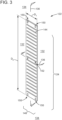
- FIGS. 3 , 4 , and 5 depict examples of the thin plate 122. These examples embody different configurations for the body 124. The configurations may adapt the mounting substrate 118 for use in the instrument panel 112, for example, with variations in some features including one or more dimensions (D 1 , D 2 ) for the body 124 or dimensions or locations for the openings 144, 146, among others.
- FIG. 3 depicts the body 124 with dimension Di set to form a thin strip 148.
- This example also incorporates open-ended slots 150 that penetrate from the sides 134 toward the bisecting plane 138. Through-holes 152 may align on the bisecting plane 136. Both the slots 150 and the holes 152 may set in from the sides 132 toward the bisecting plane 136.
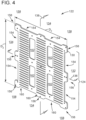
- FIG. 4 shows the body 124 with cut-outs 154 that populate the peripheral edge 130.
- the cut-outs 154 create flange members 156. Examples of the flange members 156 reside at corners 158 and on the sides 132, 134 at bisecting planes 136, 138.
- the length of the elongate slots 144 may allow for a plurality of arrays 160, shown here spaced apart from one another across the mounting area 140. Openings 162 may populate space between adjacent arrays 158.
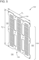
- the openings 162 may serve to reduce weight of the plate 122. As best shown in FIG. 5 , dimension Di may reduce the size of the body 124 to fit only one cut-out 154 on the sides 134.
- FIGS. 6 and 7 depict perspective views of exemplary structure for the main support 116 of the control assembly 100.
- This structure provides appropriate physical support, access, protection, or security to the control components 114.
- the structure may locate in myriad locations, including as an above-ground part of the flow control 102 or part of other control components that may work to control the flow control 102 or process or pipeline at the facility.
- FIG. 6 shows the main support 116 configured as an open-air support.
- This configuration may include mounting brackets 164, for example, metal bar stock or tube. These pieces may secure to an elongate member 166 with ends (e.g., a first end 168 and a second ends 170). Steel or metal tubes may operate as the elongate member 166 in many designs. Fasteners or welding are two techniques to secure the mounting brackets 164 in position, but other techniques are not excluded from this disclosure.
- the elongate member 166 On the first end 168, the elongate member 166 may have a flange 172 with openings 174.
- the flange 172 may secure to a base B, like a concrete pedestal. In one implementation, the base B may incorporate part of the flow control 102 ( FIG.
- the elongate member 166 may benefit from a receiving member 176, for example, a robust eyelet or hook.
- This component may operate as a location of connection for a hoist or elevator device to engage in order to lift the control assembly 100 for transport between locations, for example, from a cargo container or pallet.
- the mounting brackets 164 may support one or more of the plates 122. Threaded or unthreaded holes may populate the brackets 164 to receive fasteners that secure the plates 122, shown here as strips 148. The fasteners may penetrate through slots 150 and through-holes 152 into the corresponding threaded or unthreaded holes in the mounting brackets 164. Multiple holes on the brackets 164 may allow for variations in the position of the strips 148. In one implementation, two of the strips 148 are show on the "front" and one on the "back” of the control assembly 100. But the design may accommodate more or less as necessary, for example, by increasing or decreasing the length of the brackets 164.
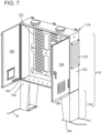
- FIG. 7 shows the main support 116 configured to enclose the control components 114.
- This configuration may embody a cabinet 178 with a peripheral wall 180, typically sheet metal that is fabricated to form a "box" with sides 182 and an open front 184.
- One of the plates 122 may affix to the sides 182 inside of the box. Additional plates 122 may also mount to the sides 182 on the outside of the box, as well.
- This configuration may include mechanics 186 to regulate access to the inside of the box.
- the mechanics 186 may include one or more door members 188 that affix to the sides 182 via a hinge 190. Other mechanisms (e.g., sliders, rollers, etc.) may be used in place of the hinge 190 as well.
- the cabinet 178 may reside on legs 192. Construction for the legs 192 may also comprise bent metal. This construction may include feet 194 to adapt the legs 192 to secure to the base B.
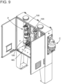
- FIGS. 8 and 9 depict perspective views of examples of the control assembly 100.
- the mounting modular mounting system 120 may include mounting members 196.
- Examples of the mounting members 196 may be thin, elongate plates, metal blocks of various shapes (e.g., square, rectangular, circular, etc.), or bent metal brackets (e.g., L-brackets).
- These components may include one or more apertures 198 that penetrate the material. In use, the apertures 198 may align with one or more of the slots 144 when the members 196 are brought in abutment with the mounting substrate 118.
- Fasteners including nuts and bolts may, in turn, provide secure engagement of the mounting members 196 so as to position control components 116 for use in the control assembly 100.
- the control components 116 may include pilot valves (PV), manual controls (MC), bleed valves (BV), and canisters (C). But other devices may find use in the control assembly 100 and, thus, leverage the construction of the mounting members 196. At least one benefit of this design is to allow for variations in the position of these components relative to, for example, bisecting planes 136, 138.
- the mounting member 196 can secure to different slots 144 on the mounting substrate 118.
- this disclosure describes improvements to control structure for heavy duty actuators. These improvements provide structure to facilitate final assembly of control stations. This structure affords more flexibility in design and integration of control components, while at the same time avoiding post fabrication machining and other processes that can add costs in parts and labor to the overall manufactured product.
Landscapes
- Engineering & Computer Science (AREA)
- General Engineering & Computer Science (AREA)
- Physics & Mathematics (AREA)
- Mechanical Engineering (AREA)
- Fluid Mechanics (AREA)
- General Physics & Mathematics (AREA)
- Automation & Control Theory (AREA)
- Valve Housings (AREA)
- Details Of Valves (AREA)
- Prostheses (AREA)
Applications Claiming Priority (4)
| Application Number | Priority Date | Filing Date | Title |
|---|---|---|---|
| US201762536778P | 2017-07-25 | 2017-07-25 | |
| US201762560956P | 2017-09-20 | 2017-09-20 | |
| US16/039,430 US10876649B2 (en) | 2017-07-25 | 2018-07-19 | Manufacture of remote control stations for use to operate actuators on a valve assembly |
| PCT/US2018/043210 WO2019023086A1 (en) | 2017-07-25 | 2018-07-23 | IMPROVING THE MANUFACTURE OF REMOTE CONTROL STATIONS FOR USE IN OPERATING ACTUATORS ON A VALVE ASSEMBLY |
Publications (3)
| Publication Number | Publication Date |
|---|---|
| EP3658809A1 EP3658809A1 (en) | 2020-06-03 |
| EP3658809A4 EP3658809A4 (en) | 2021-04-07 |
| EP3658809B1 true EP3658809B1 (en) | 2023-09-20 |
Family
ID=65038061
Family Applications (1)
| Application Number | Title | Priority Date | Filing Date |
|---|---|---|---|
| EP18839419.1A Active EP3658809B1 (en) | 2017-07-25 | 2018-07-23 | Improving manufacture of remote control stations for use to operate actuators on a valve assembly |
Country Status (7)
| Country | Link |
|---|---|
| US (1) | US10876649B2 (https=) |
| EP (1) | EP3658809B1 (https=) |
| JP (1) | JP6900569B2 (https=) |
| CN (1) | CN110869658B (https=) |
| ES (1) | ES2963261T3 (https=) |
| SG (1) | SG11202000290WA (https=) |
| WO (1) | WO2019023086A1 (https=) |
Citations (1)
| Publication number | Priority date | Publication date | Assignee | Title |
|---|---|---|---|---|
| US20020108740A1 (en) * | 2001-02-02 | 2002-08-15 | Haretaro Hidaka | Integrated piping plate, machining method for same, machining apparatus for same, and machining equipment for same |
Family Cites Families (48)
| Publication number | Priority date | Publication date | Assignee | Title |
|---|---|---|---|---|
| US3034844A (en) | 1958-01-21 | 1962-05-15 | Amco Eng | Enclosure |
| US3136442A (en) * | 1959-04-22 | 1964-06-09 | Badger Co | Casing for integrated operating air supply and air signal transmission service center |
| US3521664A (en) * | 1968-04-23 | 1970-07-28 | Edward J Medici | Valve supporting panel board assembly |
| US3751127A (en) | 1970-09-10 | 1973-08-07 | Telecommunication Technology I | Modular instrument housing |
| DE2342866C2 (de) | 1973-08-24 | 1983-11-24 | Siemens AG, 1000 Berlin und 8000 München | Bauelementesystem zum Aufbau von Schalttafeln |
| US4008931A (en) | 1975-09-17 | 1977-02-22 | Lincoln Manufacturing Company, Inc. | End panel construction for modular units and modular unit embodying the end panel construction |
| CA1096243A (en) | 1978-10-18 | 1981-02-24 | Crane Canada Limited | Valve indicator post |
| US4352532A (en) * | 1980-09-15 | 1982-10-05 | Robertshaw Controls Company | Manifolding means for electrical and/or pneumatic control units and parts and methods therefor |
| US4372410A (en) | 1980-11-10 | 1983-02-08 | Fiat-Allis Construction Machinery, Inc. | Modular instrument console |
| US4708160A (en) | 1986-08-25 | 1987-11-24 | Amsted Industries Incorporated | Post assembly for buried valve having an above ground actuator |
| US5046789A (en) | 1990-04-05 | 1991-09-10 | Alvin Lee Jewelry, Inc. | Modular panel assembly |
| US5088571A (en) | 1990-12-17 | 1992-02-18 | General Motors Corporation | Modular structural instrument panel carrier |
| US5257583A (en) | 1992-06-17 | 1993-11-02 | Mosler, Inc. | Multi-layer panels for modular vault structure |
| US5364159A (en) | 1993-06-15 | 1994-11-15 | Davidson Textron Inc. | Structural instrument panel carrier assembly |
| DE9314415U1 (de) * | 1993-09-24 | 1993-12-02 | Festo Kg, 73734 Esslingen | Befestigungsplatte |
| US5484221A (en) | 1994-03-07 | 1996-01-16 | Rockwell International Corp. | Panel mounting system |
| US5810031A (en) * | 1996-02-21 | 1998-09-22 | Aeroquip Corporation | Ultra high purity gas distribution component with integral valved coupling and methods for its use |
| US5738140A (en) | 1996-12-26 | 1998-04-14 | American Cast Iron Pipe Company | Adjustable height extension stem and valve box assembly |
| US6076543A (en) * | 1997-11-06 | 2000-06-20 | United States Filter Corporation | Gas handling device |
| JP3407108B2 (ja) | 2000-01-20 | 2003-05-19 | 英雄 松原 | 建築物の構造の形成方法 |
| US6484747B2 (en) * | 2000-04-05 | 2002-11-26 | Jerry S. Bridgers | Medical gas utility stand |
| WO2003001637A1 (en) | 2001-06-22 | 2003-01-03 | Ramesh Roahan | A weather proof enclosure with a modular structure |
| US6536614B2 (en) | 2001-07-16 | 2003-03-25 | Chih-Yu Hsia | Shelves with modular panels and accessories |
| US6560106B2 (en) | 2001-08-31 | 2003-05-06 | Hewlett Packard Development Company, L.P. | Control panel assembly |
| GB0206887D0 (en) | 2002-03-22 | 2002-05-01 | Tyco Electronics Ltd Uk | Modular housing for electrical instrument and mounting member therefor |
| US7271335B2 (en) | 2003-09-29 | 2007-09-18 | Thomas & Betts International, Inc. | Combination mounting bracket and adapter plate for mounting electrical boxes |
| US7039965B1 (en) * | 2003-11-07 | 2006-05-09 | Sioux Chief Manufacturing Co., Inc. | Notched plumbing support bracket |
| EP2185383B1 (de) | 2007-08-10 | 2014-04-16 | Johnson Controls Interiors GmbH & Co. KG | Kabelführung an einer fahrzeugtür oder flachkabelverbindung |
| DE102008031841A1 (de) | 2008-07-05 | 2010-01-07 | Recticel Automobilsysteme Gmbh | Verfahren zum Herstellen einer Formhaut sowie Formhaut |
| US8003899B2 (en) | 2008-11-25 | 2011-08-23 | Mettler-Toledo, Inc. | Mounting for industrial instrumentation |
| US8286521B2 (en) | 2009-03-26 | 2012-10-16 | Lockheed Martin Corporation | Control panel actuator device |
| PL2361598T3 (pl) * | 2010-02-22 | 2017-06-30 | Mc Health Tech, S.L. | Urządzenie nośne do zespołu do zabiegów na skórze |
| CN102782282B (zh) * | 2010-03-18 | 2016-01-27 | 三菱电机株式会社 | 空气旁通阀装置 |
| JP2012037050A (ja) * | 2010-07-12 | 2012-02-23 | Ihara Science Corp | 流体システム |
| JP5775696B2 (ja) * | 2011-01-31 | 2015-09-09 | 株式会社フジキン | 流体制御装置 |
| JP5972294B2 (ja) | 2011-03-14 | 2016-08-17 | アディタッズ,インク. | 構造的な骨組建築物のためのモジュール内部パーティション |
| US9945142B2 (en) | 2011-04-06 | 2018-04-17 | Fmr Llc | Modular data center |
| US20140109990A1 (en) | 2012-10-19 | 2014-04-24 | Toby Brashear | Remotely mounted irrigation control system |
| JP5545511B2 (ja) | 2012-05-23 | 2014-07-09 | 横河電機株式会社 | バルブ遠隔操作装置 |
| JP5522808B2 (ja) * | 2012-09-26 | 2014-06-18 | 日本フイツシヤ株式会社 | 遮断弁遠隔開閉システム |
| US9502874B2 (en) * | 2013-03-12 | 2016-11-22 | Brainwave Research Corporation | Bracket and sleeve assembly |
| US9109354B2 (en) | 2013-07-17 | 2015-08-18 | University Of Dayton | Rapid assembly of a modular structure |
| CN203453588U (zh) * | 2013-08-20 | 2014-02-26 | 苏州新智机电工业有限公司 | 增强过滤能力的单通道气动控制阀 |
| CN203537692U (zh) | 2013-11-06 | 2014-04-09 | 西安市伟创科技有限责任公司 | 一种模块式拼装电子设备机柜 |
| CN203637953U (zh) | 2013-12-20 | 2014-06-11 | 东风汽车公司 | 仪表板横梁固定结构 |
| US9482780B2 (en) | 2014-06-27 | 2016-11-01 | Douglas D. Haas | Modular instrumented floor covering |
| EP3256810B1 (en) | 2015-02-13 | 2020-05-06 | Defenshield, Inc. | Barrier |
| JP6590137B2 (ja) | 2015-02-13 | 2019-10-16 | 横河電機株式会社 | バルブ遠隔操作装置 |
-
2018
- 2018-07-19 US US16/039,430 patent/US10876649B2/en active Active
- 2018-07-23 JP JP2020500608A patent/JP6900569B2/ja active Active
- 2018-07-23 ES ES18839419T patent/ES2963261T3/es active Active
- 2018-07-23 SG SG11202000290WA patent/SG11202000290WA/en unknown
- 2018-07-23 WO PCT/US2018/043210 patent/WO2019023086A1/en not_active Ceased
- 2018-07-23 EP EP18839419.1A patent/EP3658809B1/en active Active
- 2018-07-23 CN CN201880044881.3A patent/CN110869658B/zh active Active
Patent Citations (1)
| Publication number | Priority date | Publication date | Assignee | Title |
|---|---|---|---|---|
| US20020108740A1 (en) * | 2001-02-02 | 2002-08-15 | Haretaro Hidaka | Integrated piping plate, machining method for same, machining apparatus for same, and machining equipment for same |
Also Published As
| Publication number | Publication date |
|---|---|
| JP6900569B2 (ja) | 2021-07-07 |
| SG11202000290WA (en) | 2020-02-27 |
| EP3658809A1 (en) | 2020-06-03 |
| US10876649B2 (en) | 2020-12-29 |
| ES2963261T3 (es) | 2024-03-26 |
| CN110869658A (zh) | 2020-03-06 |
| CN110869658B (zh) | 2022-03-29 |
| WO2019023086A1 (en) | 2019-01-31 |
| US20190032810A1 (en) | 2019-01-31 |
| JP2020526720A (ja) | 2020-08-31 |
| EP3658809A4 (en) | 2021-04-07 |
Similar Documents
| Publication | Publication Date | Title |
|---|---|---|
| EP3658809B1 (en) | Improving manufacture of remote control stations for use to operate actuators on a valve assembly | |
| KR20210140779A (ko) | 가스 전달을 위한 모듈형 컴포넌트 시스템 | |
| EP2573408B1 (en) | Solenoid valve bypass system for continuous operation of pneumatic valve and method therefor | |
| EP3262986A1 (en) | Museum showcase | |
| US7347204B1 (en) | Breathing air system for a facility | |
| CA2539327C (en) | Universal bracket and method for transporting an assembled conduit | |
| US10683949B1 (en) | Universal, adjustable, spliceable, bracket forming, and strapping material | |
| SG11202110010QA (en) | Improved valve control assembly | |
| EP2661571B1 (en) | Check valve for a pipe section | |
| US6913034B2 (en) | Emergency shutdown valve actuator | |
| US11079038B2 (en) | Manufacture of actuators and control valve assemblies | |
| US20120192964A1 (en) | Fluid control apparatus | |
| TWI639775B (zh) | 致動器的導引單元 | |
| ES2405613T3 (es) | Módulo de filtro con control del flujo | |
| CA2979348A1 (en) | Redundant vents with unitary valve bodies for water-based fire sprinkler systems | |
| RU2747394C1 (ru) | Установка настройки регулятора давления газа | |
| JP6396520B2 (ja) | 空気調和装置の室内機 | |
| EP4419823A1 (en) | Installing trim in a valve assembly | |
| CN218973521U (zh) | 气路分配装置、分析仪表测试系统和压力仪表测试系统 | |
| Hirvi | Structural and flow optimized design of a multiple outlet pressure vessel | |
| US20240399387A1 (en) | Apparatus, systems and methods for use in ferrous particle removal from a fluid | |
| Chang et al. | A case study of ergonomic evaluation for the control rooms of a petroleum complex | |
| BR112016019408B1 (pt) | módulos de grade livres de gaxetas para suporte de catalisador e um sistema modular disto | |
| Ray et al. | International Space Station Internal Thermal Control System Cold Plate/Fluid-Stability Test Setup and Preliminary Test Results | |
| GB2584475A (en) | Nozzle check valve assembly |
Legal Events
| Date | Code | Title | Description |
|---|---|---|---|
| STAA | Information on the status of an ep patent application or granted ep patent |
Free format text: STATUS: THE INTERNATIONAL PUBLICATION HAS BEEN MADE |
|
| PUAI | Public reference made under article 153(3) epc to a published international application that has entered the european phase |
Free format text: ORIGINAL CODE: 0009012 |
|
| STAA | Information on the status of an ep patent application or granted ep patent |
Free format text: STATUS: REQUEST FOR EXAMINATION WAS MADE |
|
| 17P | Request for examination filed |
Effective date: 20200220 |
|
| AK | Designated contracting states |
Kind code of ref document: A1 Designated state(s): AL AT BE BG CH CY CZ DE DK EE ES FI FR GB GR HR HU IE IS IT LI LT LU LV MC MK MT NL NO PL PT RO RS SE SI SK SM TR |
|
| AX | Request for extension of the european patent |
Extension state: BA ME |
|
| DAV | Request for validation of the european patent (deleted) | ||
| DAX | Request for extension of the european patent (deleted) | ||
| A4 | Supplementary search report drawn up and despatched |
Effective date: 20210304 |
|
| RIC1 | Information provided on ipc code assigned before grant |
Ipc: F16K 51/00 20060101AFI20210226BHEP Ipc: F16K 31/12 20060101ALI20210226BHEP Ipc: F15B 13/08 20060101ALI20210226BHEP |
|
| STAA | Information on the status of an ep patent application or granted ep patent |
Free format text: STATUS: EXAMINATION IS IN PROGRESS |
|
| 17Q | First examination report despatched |
Effective date: 20220510 |
|
| GRAP | Despatch of communication of intention to grant a patent |
Free format text: ORIGINAL CODE: EPIDOSNIGR1 |
|
| STAA | Information on the status of an ep patent application or granted ep patent |
Free format text: STATUS: GRANT OF PATENT IS INTENDED |
|
| P01 | Opt-out of the competence of the unified patent court (upc) registered |
Effective date: 20230526 |
|
| INTG | Intention to grant announced |
Effective date: 20230619 |
|
| GRAS | Grant fee paid |
Free format text: ORIGINAL CODE: EPIDOSNIGR3 |
|
| GRAA | (expected) grant |
Free format text: ORIGINAL CODE: 0009210 |
|
| STAA | Information on the status of an ep patent application or granted ep patent |
Free format text: STATUS: THE PATENT HAS BEEN GRANTED |
|
| AK | Designated contracting states |
Kind code of ref document: B1 Designated state(s): AL AT BE BG CH CY CZ DE DK EE ES FI FR GB GR HR HU IE IS IT LI LT LU LV MC MK MT NL NO PL PT RO RS SE SI SK SM TR |
|
| REG | Reference to a national code |
Ref country code: GB Ref legal event code: FG4D |
|
| REG | Reference to a national code |
Ref country code: CH Ref legal event code: EP |
|
| REG | Reference to a national code |
Ref country code: IE Ref legal event code: FG4D |
|
| REG | Reference to a national code |
Ref country code: DE Ref legal event code: R096 Ref document number: 602018058019 Country of ref document: DE |
|
| REG | Reference to a national code |
Ref country code: LT Ref legal event code: MG9D |
|
| PG25 | Lapsed in a contracting state [announced via postgrant information from national office to epo] |
Ref country code: GR Free format text: LAPSE BECAUSE OF FAILURE TO SUBMIT A TRANSLATION OF THE DESCRIPTION OR TO PAY THE FEE WITHIN THE PRESCRIBED TIME-LIMIT Effective date: 20231221 |
|
| REG | Reference to a national code |
Ref country code: NL Ref legal event code: MP Effective date: 20230920 |
|
| PG25 | Lapsed in a contracting state [announced via postgrant information from national office to epo] |
Ref country code: SE Free format text: LAPSE BECAUSE OF FAILURE TO SUBMIT A TRANSLATION OF THE DESCRIPTION OR TO PAY THE FEE WITHIN THE PRESCRIBED TIME-LIMIT Effective date: 20230920 Ref country code: RS Free format text: LAPSE BECAUSE OF FAILURE TO SUBMIT A TRANSLATION OF THE DESCRIPTION OR TO PAY THE FEE WITHIN THE PRESCRIBED TIME-LIMIT Effective date: 20230920 Ref country code: NO Free format text: LAPSE BECAUSE OF FAILURE TO SUBMIT A TRANSLATION OF THE DESCRIPTION OR TO PAY THE FEE WITHIN THE PRESCRIBED TIME-LIMIT Effective date: 20231220 Ref country code: LV Free format text: LAPSE BECAUSE OF FAILURE TO SUBMIT A TRANSLATION OF THE DESCRIPTION OR TO PAY THE FEE WITHIN THE PRESCRIBED TIME-LIMIT Effective date: 20230920 Ref country code: LT Free format text: LAPSE BECAUSE OF FAILURE TO SUBMIT A TRANSLATION OF THE DESCRIPTION OR TO PAY THE FEE WITHIN THE PRESCRIBED TIME-LIMIT Effective date: 20230920 Ref country code: HR Free format text: LAPSE BECAUSE OF FAILURE TO SUBMIT A TRANSLATION OF THE DESCRIPTION OR TO PAY THE FEE WITHIN THE PRESCRIBED TIME-LIMIT Effective date: 20230920 Ref country code: GR Free format text: LAPSE BECAUSE OF FAILURE TO SUBMIT A TRANSLATION OF THE DESCRIPTION OR TO PAY THE FEE WITHIN THE PRESCRIBED TIME-LIMIT Effective date: 20231221 Ref country code: FI Free format text: LAPSE BECAUSE OF FAILURE TO SUBMIT A TRANSLATION OF THE DESCRIPTION OR TO PAY THE FEE WITHIN THE PRESCRIBED TIME-LIMIT Effective date: 20230920 |
|
| REG | Reference to a national code |
Ref country code: AT Ref legal event code: MK05 Ref document number: 1613611 Country of ref document: AT Kind code of ref document: T Effective date: 20230920 |
|
| PG25 | Lapsed in a contracting state [announced via postgrant information from national office to epo] |
Ref country code: NL Free format text: LAPSE BECAUSE OF FAILURE TO SUBMIT A TRANSLATION OF THE DESCRIPTION OR TO PAY THE FEE WITHIN THE PRESCRIBED TIME-LIMIT Effective date: 20230920 |
|
| REG | Reference to a national code |
Ref country code: ES Ref legal event code: FG2A Ref document number: 2963261 Country of ref document: ES Kind code of ref document: T3 Effective date: 20240326 |
|
| PG25 | Lapsed in a contracting state [announced via postgrant information from national office to epo] |
Ref country code: IS Free format text: LAPSE BECAUSE OF FAILURE TO SUBMIT A TRANSLATION OF THE DESCRIPTION OR TO PAY THE FEE WITHIN THE PRESCRIBED TIME-LIMIT Effective date: 20240120 |
|
| PG25 | Lapsed in a contracting state [announced via postgrant information from national office to epo] |
Ref country code: AT Free format text: LAPSE BECAUSE OF FAILURE TO SUBMIT A TRANSLATION OF THE DESCRIPTION OR TO PAY THE FEE WITHIN THE PRESCRIBED TIME-LIMIT Effective date: 20230920 |
|
| PG25 | Lapsed in a contracting state [announced via postgrant information from national office to epo] |
Ref country code: SM Free format text: LAPSE BECAUSE OF FAILURE TO SUBMIT A TRANSLATION OF THE DESCRIPTION OR TO PAY THE FEE WITHIN THE PRESCRIBED TIME-LIMIT Effective date: 20230920 Ref country code: RO Free format text: LAPSE BECAUSE OF FAILURE TO SUBMIT A TRANSLATION OF THE DESCRIPTION OR TO PAY THE FEE WITHIN THE PRESCRIBED TIME-LIMIT Effective date: 20230920 Ref country code: IS Free format text: LAPSE BECAUSE OF FAILURE TO SUBMIT A TRANSLATION OF THE DESCRIPTION OR TO PAY THE FEE WITHIN THE PRESCRIBED TIME-LIMIT Effective date: 20240120 Ref country code: EE Free format text: LAPSE BECAUSE OF FAILURE TO SUBMIT A TRANSLATION OF THE DESCRIPTION OR TO PAY THE FEE WITHIN THE PRESCRIBED TIME-LIMIT Effective date: 20230920 Ref country code: CZ Free format text: LAPSE BECAUSE OF FAILURE TO SUBMIT A TRANSLATION OF THE DESCRIPTION OR TO PAY THE FEE WITHIN THE PRESCRIBED TIME-LIMIT Effective date: 20230920 Ref country code: AT Free format text: LAPSE BECAUSE OF FAILURE TO SUBMIT A TRANSLATION OF THE DESCRIPTION OR TO PAY THE FEE WITHIN THE PRESCRIBED TIME-LIMIT Effective date: 20230920 Ref country code: SK Free format text: LAPSE BECAUSE OF FAILURE TO SUBMIT A TRANSLATION OF THE DESCRIPTION OR TO PAY THE FEE WITHIN THE PRESCRIBED TIME-LIMIT Effective date: 20230920 Ref country code: PT Free format text: LAPSE BECAUSE OF FAILURE TO SUBMIT A TRANSLATION OF THE DESCRIPTION OR TO PAY THE FEE WITHIN THE PRESCRIBED TIME-LIMIT Effective date: 20240122 |
|
| PG25 | Lapsed in a contracting state [announced via postgrant information from national office to epo] |
Ref country code: PL Free format text: LAPSE BECAUSE OF FAILURE TO SUBMIT A TRANSLATION OF THE DESCRIPTION OR TO PAY THE FEE WITHIN THE PRESCRIBED TIME-LIMIT Effective date: 20230920 |
|
| REG | Reference to a national code |
Ref country code: DE Ref legal event code: R097 Ref document number: 602018058019 Country of ref document: DE |
|
| PG25 | Lapsed in a contracting state [announced via postgrant information from national office to epo] |
Ref country code: DK Free format text: LAPSE BECAUSE OF FAILURE TO SUBMIT A TRANSLATION OF THE DESCRIPTION OR TO PAY THE FEE WITHIN THE PRESCRIBED TIME-LIMIT Effective date: 20230920 |
|
| PLBE | No opposition filed within time limit |
Free format text: ORIGINAL CODE: 0009261 |
|
| STAA | Information on the status of an ep patent application or granted ep patent |
Free format text: STATUS: NO OPPOSITION FILED WITHIN TIME LIMIT |
|
| PG25 | Lapsed in a contracting state [announced via postgrant information from national office to epo] |
Ref country code: DK Free format text: LAPSE BECAUSE OF FAILURE TO SUBMIT A TRANSLATION OF THE DESCRIPTION OR TO PAY THE FEE WITHIN THE PRESCRIBED TIME-LIMIT Effective date: 20230920 |
|
| 26N | No opposition filed |
Effective date: 20240621 |
|
| PG25 | Lapsed in a contracting state [announced via postgrant information from national office to epo] |
Ref country code: SI Free format text: LAPSE BECAUSE OF FAILURE TO SUBMIT A TRANSLATION OF THE DESCRIPTION OR TO PAY THE FEE WITHIN THE PRESCRIBED TIME-LIMIT Effective date: 20230920 |
|
| PG25 | Lapsed in a contracting state [announced via postgrant information from national office to epo] |
Ref country code: SI Free format text: LAPSE BECAUSE OF FAILURE TO SUBMIT A TRANSLATION OF THE DESCRIPTION OR TO PAY THE FEE WITHIN THE PRESCRIBED TIME-LIMIT Effective date: 20230920 |
|
| PG25 | Lapsed in a contracting state [announced via postgrant information from national office to epo] |
Ref country code: BG Free format text: LAPSE BECAUSE OF FAILURE TO SUBMIT A TRANSLATION OF THE DESCRIPTION OR TO PAY THE FEE WITHIN THE PRESCRIBED TIME-LIMIT Effective date: 20230920 |
|
| PG25 | Lapsed in a contracting state [announced via postgrant information from national office to epo] |
Ref country code: BG Free format text: LAPSE BECAUSE OF FAILURE TO SUBMIT A TRANSLATION OF THE DESCRIPTION OR TO PAY THE FEE WITHIN THE PRESCRIBED TIME-LIMIT Effective date: 20230920 |
|
| PG25 | Lapsed in a contracting state [announced via postgrant information from national office to epo] |
Ref country code: MC Free format text: LAPSE BECAUSE OF FAILURE TO SUBMIT A TRANSLATION OF THE DESCRIPTION OR TO PAY THE FEE WITHIN THE PRESCRIBED TIME-LIMIT Effective date: 20230920 |
|
| REG | Reference to a national code |
Ref country code: CH Ref legal event code: PL |
|
| PG25 | Lapsed in a contracting state [announced via postgrant information from national office to epo] |
Ref country code: LU Free format text: LAPSE BECAUSE OF NON-PAYMENT OF DUE FEES Effective date: 20240723 |
|
| PG25 | Lapsed in a contracting state [announced via postgrant information from national office to epo] |
Ref country code: LU Free format text: LAPSE BECAUSE OF NON-PAYMENT OF DUE FEES Effective date: 20240723 |
|
| PG25 | Lapsed in a contracting state [announced via postgrant information from national office to epo] |
Ref country code: CH Free format text: LAPSE BECAUSE OF NON-PAYMENT OF DUE FEES Effective date: 20240731 Ref country code: BE Free format text: LAPSE BECAUSE OF NON-PAYMENT OF DUE FEES Effective date: 20240731 |
|
| REG | Reference to a national code |
Ref country code: BE Ref legal event code: MM Effective date: 20240731 |
|
| PGFP | Annual fee paid to national office [announced via postgrant information from national office to epo] |
Ref country code: GB Payment date: 20250619 Year of fee payment: 8 |
|
| PGFP | Annual fee paid to national office [announced via postgrant information from national office to epo] |
Ref country code: FR Payment date: 20250619 Year of fee payment: 8 |
|
| PG25 | Lapsed in a contracting state [announced via postgrant information from national office to epo] |
Ref country code: IE Free format text: LAPSE BECAUSE OF NON-PAYMENT OF DUE FEES Effective date: 20240723 |
|
| PGFP | Annual fee paid to national office [announced via postgrant information from national office to epo] |
Ref country code: ES Payment date: 20250801 Year of fee payment: 8 |
|
| PGFP | Annual fee paid to national office [announced via postgrant information from national office to epo] |
Ref country code: DE Payment date: 20250620 Year of fee payment: 8 |
|
| PGFP | Annual fee paid to national office [announced via postgrant information from national office to epo] |
Ref country code: IT Payment date: 20250619 Year of fee payment: 8 |
|
| PG25 | Lapsed in a contracting state [announced via postgrant information from national office to epo] |
Ref country code: CY Free format text: LAPSE BECAUSE OF FAILURE TO SUBMIT A TRANSLATION OF THE DESCRIPTION OR TO PAY THE FEE WITHIN THE PRESCRIBED TIME-LIMIT; INVALID AB INITIO Effective date: 20180723 |
|
| PG25 | Lapsed in a contracting state [announced via postgrant information from national office to epo] |
Ref country code: HU Free format text: LAPSE BECAUSE OF FAILURE TO SUBMIT A TRANSLATION OF THE DESCRIPTION OR TO PAY THE FEE WITHIN THE PRESCRIBED TIME-LIMIT; INVALID AB INITIO Effective date: 20180723 |