EP3657638A1 - Rotor de moteur électrique ainsi que moteur électrique - Google Patents
Rotor de moteur électrique ainsi que moteur électrique Download PDFInfo
- Publication number
- EP3657638A1 EP3657638A1 EP19203516.0A EP19203516A EP3657638A1 EP 3657638 A1 EP3657638 A1 EP 3657638A1 EP 19203516 A EP19203516 A EP 19203516A EP 3657638 A1 EP3657638 A1 EP 3657638A1
- Authority
- EP
- European Patent Office
- Prior art keywords
- rotor
- edge
- magnet
- circumferential direction
- web
- Prior art date
- Legal status (The legal status is an assumption and is not a legal conclusion. Google has not performed a legal analysis and makes no representation as to the accuracy of the status listed.)
- Withdrawn
Links
Images


Classifications
-
- H—ELECTRICITY
- H02—GENERATION; CONVERSION OR DISTRIBUTION OF ELECTRIC POWER
- H02K—DYNAMO-ELECTRIC MACHINES
- H02K29/00—Motors or generators having non-mechanical commutating devices, e.g. discharge tubes or semiconductor devices
- H02K29/03—Motors or generators having non-mechanical commutating devices, e.g. discharge tubes or semiconductor devices with a magnetic circuit specially adapted for avoiding torque ripples or self-starting problems
-
- H—ELECTRICITY
- H02—GENERATION; CONVERSION OR DISTRIBUTION OF ELECTRIC POWER
- H02K—DYNAMO-ELECTRIC MACHINES
- H02K1/00—Details of the magnetic circuit
- H02K1/06—Details of the magnetic circuit characterised by the shape, form or construction
- H02K1/22—Rotating parts of the magnetic circuit
- H02K1/27—Rotor cores with permanent magnets
- H02K1/2706—Inner rotors
- H02K1/272—Inner rotors the magnetisation axis of the magnets being perpendicular to the rotor axis
- H02K1/274—Inner rotors the magnetisation axis of the magnets being perpendicular to the rotor axis the rotor consisting of two or more circumferentially positioned magnets
- H02K1/2753—Inner rotors the magnetisation axis of the magnets being perpendicular to the rotor axis the rotor consisting of two or more circumferentially positioned magnets the rotor consisting of magnets or groups of magnets arranged with alternating polarity
- H02K1/276—Magnets embedded in the magnetic core, e.g. interior permanent magnets [IPM]
- H02K1/2766—Magnets embedded in the magnetic core, e.g. interior permanent magnets [IPM] having a flux concentration effect
-
- H—ELECTRICITY
- H02—GENERATION; CONVERSION OR DISTRIBUTION OF ELECTRIC POWER
- H02K—DYNAMO-ELECTRIC MACHINES
- H02K2201/00—Specific aspects not provided for in the other groups of this subclass relating to the magnetic circuits
- H02K2201/06—Magnetic cores, or permanent magnets characterised by their skew
Definitions
- the present invention relates to a rotor of an electric motor.
- the invention also relates to an electric motor comprising such a rotor.
- Electric motors are known from the prior art.
- the problem of cogging torques in electric motors is also known.
- either the stator or the rotor is built up at an angle in the case of permanently excited electric motors.
- the magnetic flux is shifted by several angular degrees over the axial length of the rotor or stator. This means that the individual poles do not come under the influence of the stator field at the same time.
- Such an inclined structure is for example from the DE 10 2014 019 218 A1 known.
- the flow within the electric motor is not controlled by the offset of the magnets as in the prior art, but by a shape of the sheet metal cut of the rotor laminated core of the rotor of the electric motor. It is thus in particular avoidable that magnets collide in a displaced manner, as is the case in the prior art. In these areas, there are the power-reducing 3D magnetic circuits that are eliminated with the invention.
- magnetization of the magnets in the oversaturated region is simplified and in particular also completed, since the magnetization takes place in the same position.
- the performance of the same electric machine and / or the same electric motor can be increased, in particular due to the continuous magnetic pockets and thus more magnetic mass in the rotor.
- Bevel tolerances between the individual laminations of the rotor laminated core are eliminated.
- the degree of freedom in realizing the bevel effects also increases, since different individual sheets can be combined with one another as desired. Overall, a reduction in the overall length of the rotor is possible.
- no alignment notch on the rotor is required for the bevel, in particular, no complicated process for beveling is necessary as in the prior art.
- the magnets are all axially available at the same time.
- the rotor of an electric motor comprises a rotor body with a plurality of rotor laminated cores, each of which has a multiplicity of stacked individual laminations.
- the rotor body also has a plurality of rotor poles. Each rotor pole in turn has at least one magnetic pocket.
- the magnet pockets are in particular made as slot-shaped recesses in the individual sheets and serve to hold a permanent magnet.
- Each magnet pocket divides the respective rotor pole into radial areas. As a result, at least one radially outer pole region and one radially inner pole region are present. The radial areas are connected to one another via connecting webs.
- the connecting webs are realized in particular by areas between two magnetic pockets and / or by areas between the magnetic pocket and the air gap.
- the magnetic pockets have a central region and edge regions adjoining the central region on both sides. It is provided that the permanent magnets are only present on the central areas of the magnet pockets.
- the permanent magnets are preferably optimally arranged with respect to one another, so that parasitic 3D magnetic circuits as in the prior art are avoided.
- the edge areas of the magnet pockets are advantageously free of permanent magnets.
- the second magnet pockets are used exclusively to control the flow within the electric motor, but not to hold permanent magnets.
- the edge area thus comprises a radially outermost area of the magnet pockets.
- the air gap is defined in particular between the outer peripheral surface of the rotor and a stator of the electric motor. The magnetic flux within the electric motor can be adjusted by the corresponding configuration of the radially outermost region of the magnet pocket.
- the contour of the edge region of the magnet pocket resting on the edge web is changed in the circumferential direction from one of the rotor laminated cores to an adjacent rotor laminated core such that the magnetic flux flowing through the permanent magnet is shifted in the circumferential direction from the rotor laminated core to the adjacent rotor laminated core.
- the flow within the electric motor is thus controlled by the different design of the radially outer edge regions of the individual rotor laminated cores.
- a symmetrical magnetic flux is thus preferably achieved in part of the rotor laminated cores, while in other rotor laminated cores the magnetic flux is either shifted to the left or to the right with respect to the d-axis.
- This varies the magnetic flux.
- This leads to a cogging torque suppression and an even torque curve.
- the same effects are achieved as in the case of the rotor inclination known from the prior art, the manufacture and assembly of the rotor being considerably simplified.
- the central areas of the magnet pockets are preferably designed to be aligned in all rotor laminated core assemblies. This enables the permanent magnets to be installed easily and with little effort. At least the radially outer edge regions which abut the edge webs are particularly advantageously at least partially offset from one another. It is thus achieved in particular that the individual individual sheets of the rotor sheet stack at least partially cover the edge regions of other individual sheets of the rotor sheet stack. The magnetic pockets of the individual sheets on the edge areas are therefore not aligned and thus differ from the first partial areas. The first sub-areas, on the other hand, allow the permanent magnets to be arranged throughout.
- each edge web of a rotor pole is offset in the circumferential direction with respect to the position of its ends from one of the rotor laminated cores to an adjacent rotor laminated core.
- the radially outer edge regions of the magnet pockets are thus arranged differently. The shifting of the magnetic fluxes described above can thereby advantageously be achieved.
- Each edge web advantageously has the narrowest cross section.
- the narrowest cross-sections of all edge webs of a rotor pole are offset in particular in the circumferential direction from one of the rotor laminated cores to an adjacent rotor laminated core. The magnetic flux flowing through the permanent magnet is thus shifted, the individual laminations of the rotor laminated core being simple and inexpensive to produce.
- the contour of the edge region of the magnet pocket resting on the edge web is preferably changed in the circumferential direction over all rotor laminated cores in such a way that the magnetic flux flowing through the permanent magnets is increasingly shifted in the circumferential direction as seen across all rotor laminated cores.
- the occurrence of cogging torques is reduced, as a result of which a uniform torque curve can be achieved.
- a section of the contour of the edge regions of the magnet pockets lying against the edge webs is preferably shifted in the circumferential direction along a line running through the edge region.
- a uniform structure of the individual laminations of the rotor laminated cores is thus achieved.
- only a part of the outer edge region of each magnet pocket is designed to be displaced. It is thus achieved in particular that each individual sheet has magnet pockets of the same size, which differ only in their shape.
- the permanent magnets are advantageously arranged in a V-shape and / or a C-shape.
- the magnetic pockets are arranged in particular in layers, each layer forming a V-shaped or C-shaped arrangement.
- the rotor has single-layer C-magnet arrangements or V-magnet arrangements on permanent magnets.
- the rotor can also have multi-layer VC-W arrangements or CC arrangements. In any case, a flow of the electric motor is optimally set by the edge regions.
- the rotor body particularly advantageously has a plurality of different rotor laminated cores.
- the rotor laminated cores each comprise identical individual laminations.
- the individual laminations of different rotor laminated cores have different marginal areas lying against the respective edge webs.
- the individual sheets are stacked to form the rotor laminated core in such a way that a stacking sequence of the individual sheets has a repeating pattern at different edge regions. It can thus be achieved, in particular, that immediately adjacent individual sheets differ in their edge regions, which lie against the respective edge webs.
- the repeating pattern means that the number of different individual sheets is limited.
- a safe and reliable control of the magnetic flux is made possible, on the other hand, it is not complex to assemble the rotor laminated core of the electric motor.
- Each pattern particularly advantageously has an increasing offset in a peripheral direction of the rotor of the edge regions abutting the edge web.
- An equivalent to the skew is thus achieved in the prior art. Due to the increasing offset, each pattern can be produced easily and with little effort, since only a minimum offset, a maximum offset and the number of individual sheets with an offset between the minimum offset and the maximum offset need to be determined.
- a detailed adjustment of the flow of the electric motor is made possible, on the other hand, the rotor can be manufactured easily and with little effort.
- the magnetic pockets extend through all the rotor laminations. This advantageously applies to the central areas of the magnetic pockets. There is thus a continuous opening in the rotor body which extends through the entire rotor. Permanent magnets can thus be placed along the entire axial length of the rotor. This ensures an optimal magnetic mass of the rotor.
- each edge web has a different height above the magnetic pockets.
- the course of this is different heights advantageously identical for all edge webs. In this way, the magnetic flux within the electric motor can be optimally adjusted without negatively influencing other parameters of the rotor or the electric motor.
- the invention relates to an electric motor.
- the electric motor includes a rotor as previously described. It is provided that the rotor is driven by a stator of the electric motor. A flow within the electric motor is optimized by the arrangement of the edge areas of the magnet pockets of the rotor described above. At the same time, permanent magnets of the rotor can be attached easily and with little effort.
- the magnetic pockets and / or the individual sheets are produced in particular by stamping.
- the contour of the individual sheets and the contour of the magnetic pockets can thus be produced simply and inexpensively. This applies in particular to the different edge areas, since only different punching tools have to be provided here. This means that the individual sheets can be produced in large numbers easily and with little effort.
- the edge areas of magnet pockets of rotor laminated cores arranged adjacent in the rotor body, each with identical individual laminations, are displaced in the circumferential direction of the rotor. It is thus provided in particular that the edge regions of two adjacent rotor laminated cores are not arranged in alignment, but rather have an offset. It can be provided that two not directly adjacent rotor laminated cores have identical magnetic pockets.
- FIG. 1 schematically shows an electric motor 2 according to an embodiment of the invention.
- the electric motor 2 comprises a rotor 1 and a stator 10.
- the stator 10 is only indicated schematically by a stator tooth.
- the rotor 1 comprises a plurality of laminations of rotor laminations 3, which together form a rotor body 12 which is attached to a shaft 9.
- the rotor core 3 can thus be rotated.
- Each rotor laminated core 3 in turn comprises a plurality of identical individual laminations 4 which are stacked to form the respective laminated rotor core 3.
- the individual sheets 4 are advantageously made from an electrical sheet, in particular by stamping.
- Figure 1 is shown by way of example that there are two rotor laminated cores 3, which are stacked from two individual laminations 4 each.
- Each individual sheet 4 comprises several recesses, so that the rotor sheet packs 3 form magnetic pockets 5.
- the magnet pockets 5 have a central region 6 and edge regions 7 adjoining them on both sides, the central region 6 and edge regions 7 directly abutting one another and not being delimited from one another.
- the radially outer edge regions are always described below.
- the rotor laminated cores 3 are stacked to form the rotor body, it is provided that all central regions 6 of the magnet pockets 5 are arranged in alignment. This means that the central regions 6 are always arranged on the same region of the rotor 2 with respect to a radial direction 200 and with respect to a circumferential direction 100. This creates a continuous opening, which extends in particular over an entire length of the rotor 1. Permanent magnets 8 can be introduced into this opening.
- edge regions 7 of the magnet pockets 5 are shaped in particular in such a way that the magnetic flux running through the permanent magnet 8 is displaced in the circumferential direction 100 in the case of adjacent rotor laminated cores 3. No permanent magnets 8 are present in these edge regions 7, so that all edge regions 7 are free of permanent magnets 8.
- the shape of the edge regions 7 only serves to control the magnetic flux 300. This is described below with reference to Figure 2, Figure 3 and Figure 4 explained.
- Figure 2 shows schematically three different individual sheets 4, each of which can be stacked to form a rotor sheet stack 3. It is thus possible to implement three different laminations of rotor laminations 3, each comprising identical individual laminations 4.
- Figure 3 shows schematically an exploded view of stacked rotor laminations 3, each rotor laminate 3 a plurality of individual laminations 4 one of the in Figure 2 shown type includes.
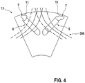
- Figure 4 finally shows a view of the stacked rotor body.
- the whole Figures 2, 3 and 4th each show only a section of a rotor pole 13 of the entire rotor 1.
- the magnet pockets 5 divide the rotor pole 13 into a radially inner pole region X and a radially outer pole region Y.
- the radially inner pole region X and the radially outer pole region Y are connected by connecting webs between the magnet pockets 5 and / or between the magnet pocket 5 and the outer circumference of the rotor 1 .
- Those connecting webs that lie between the magnet pocket 5 and the outer circumference of the rotor 1 are edge webs 11.
- the edge webs 11 are formed in particular by the contour of the edge regions 7 of the magnet pockets that abut the edge webs 11.
- the individual sheets 4 each comprise identically designed central areas 6, in which the permanent magnets 8 can be attached.
- section of the contour are on the edge webs 11 adjacent edge regions 7 of the magnet pockets 5 are displaced in the circumferential direction 100 along a line running through the edge region 7. Different magnetic fluxes 300 can thus be realized in particular.
- Figure 3 shows that the rotor laminated cores 3 are stacked to form the rotor body in such a way that a repeating pattern results from different edge regions 7 resting on the edge webs 11.
- contour sections of these edge regions 7 are displaced along the circumferential direction 100.
- adjacent rotor laminated cores 3 have edge regions 7 which abut the edge webs 11 and which are not in alignment.
- a minimal web height h remains (cf. Figure 2 ) identical for all edge webs 11.
- a smallest cross section, on which the edge webs 11 have the minimum web height h is not arranged at identical positions in the circumferential direction in the case of adjacent rotor laminated cores 3.
- Figure 3 is also shown schematically which line contour of the field lines of the magnetic flux 300 Figure 4 which rotor laminated core 3 from Figure 3 is to be assigned.
- Figure 4 it can be seen how the edge regions 7 resting on the edge webs 11 can be used to control the magnetic flux 300 of the electric motor 2.
- a result can thus be achieved which has the same effect as the inclined position of the permanent magnets 8, which is known from the prior art.
- this ensures that the individual rotor poles 13 do not all influence the influence of the stator field at the same time reach.
Landscapes
- Engineering & Computer Science (AREA)
- Power Engineering (AREA)
- Permanent Field Magnets Of Synchronous Machinery (AREA)
- Iron Core Of Rotating Electric Machines (AREA)
Applications Claiming Priority (1)
| Application Number | Priority Date | Filing Date | Title |
|---|---|---|---|
| DE102018220057.2A DE102018220057A1 (de) | 2018-11-22 | 2018-11-22 | Rotor eines Elektromotors sowie Elektromotor |
Publications (1)
| Publication Number | Publication Date |
|---|---|
| EP3657638A1 true EP3657638A1 (fr) | 2020-05-27 |
Family
ID=68281146
Family Applications (1)
| Application Number | Title | Priority Date | Filing Date |
|---|---|---|---|
| EP19203516.0A Withdrawn EP3657638A1 (fr) | 2018-11-22 | 2019-10-16 | Rotor de moteur électrique ainsi que moteur électrique |
Country Status (2)
| Country | Link |
|---|---|
| EP (1) | EP3657638A1 (fr) |
| DE (1) | DE102018220057A1 (fr) |
Cited By (1)
| Publication number | Priority date | Publication date | Assignee | Title |
|---|---|---|---|---|
| EP4366138A1 (fr) * | 2022-11-04 | 2024-05-08 | Huawei Digital Power Technologies Co., Ltd. | Rotor et moteur à aimant permanent |
Citations (2)
| Publication number | Priority date | Publication date | Assignee | Title |
|---|---|---|---|---|
| DE102014019218A1 (de) | 2014-12-19 | 2015-06-25 | Daimler Ag | Blechpaket für eine elektrische Maschine |
| WO2018188755A1 (fr) * | 2017-04-13 | 2018-10-18 | Abb Schweiz Ag | Feuille et rotor de machine électrique et leur procédé de fabrication |
-
2018
- 2018-11-22 DE DE102018220057.2A patent/DE102018220057A1/de not_active Withdrawn
-
2019
- 2019-10-16 EP EP19203516.0A patent/EP3657638A1/fr not_active Withdrawn
Patent Citations (2)
| Publication number | Priority date | Publication date | Assignee | Title |
|---|---|---|---|---|
| DE102014019218A1 (de) | 2014-12-19 | 2015-06-25 | Daimler Ag | Blechpaket für eine elektrische Maschine |
| WO2018188755A1 (fr) * | 2017-04-13 | 2018-10-18 | Abb Schweiz Ag | Feuille et rotor de machine électrique et leur procédé de fabrication |
Cited By (1)
| Publication number | Priority date | Publication date | Assignee | Title |
|---|---|---|---|---|
| EP4366138A1 (fr) * | 2022-11-04 | 2024-05-08 | Huawei Digital Power Technologies Co., Ltd. | Rotor et moteur à aimant permanent |
Also Published As
| Publication number | Publication date |
|---|---|
| DE102018220057A1 (de) | 2020-05-28 |
Similar Documents
| Publication | Publication Date | Title |
|---|---|---|
| EP3189582B1 (fr) | Rotor d'une machine électrique, machine électrique et procédé de fabrication du rotor d'une machine électrique | |
| DE112007000201T5 (de) | Geschlitzte Kerne für einen Motorstator, Motorstator, Synchronmotor des Permanentmagnetentyps, und Stanzverfahren durch Stanzstempel für geschlitzte Kerne | |
| EP2378627A1 (fr) | Moteur électrique | |
| EP2903136A1 (fr) | Tôle de rotor à réluctance dotée d'un évidement pour la réduction de la tension | |
| DE10227859A1 (de) | Induktionsmotor vom Typ mit eingebettetem Permanentmagneten, welcher leichte Durchführung der Einbettung der Spule gestattet | |
| DE10247187A1 (de) | Permanentmagnetmotor | |
| DE102012022084A1 (de) | Rotoranordnung für eine elektrische Maschine, elektrische Maschine und Verfahren zum Herstellen der Rotoranordnung | |
| DE102017102242A1 (de) | Verwendung von magnetfeldern in elektromaschinen | |
| DE102013200476A1 (de) | Permanenterregte Synchronmaschine mit einem Rotor mit Permanentmagneten und Verfahren zur Herstellung derartiger Maschinen bzw. Rotoren | |
| EP2479872B1 (fr) | Machine synchrone excitée en permanence dotée d'un rotor | |
| EP3381107B1 (fr) | Tole electrique dotee d'une ame imprimee | |
| EP2942858B1 (fr) | Paquet de tôles de rotor | |
| DE2416610A1 (de) | Permanentmagnet-synchronmotor | |
| WO2013053479A1 (fr) | Ensemble de tôles de rotor et procédé de fabrication | |
| EP1964240A1 (fr) | Rotor d'une machine électrique, notamment d'un moteur, et procédé pour fabriquer un rotor | |
| EP3742583A1 (fr) | Moteur à réluctance synchrone quadripolaire | |
| DE102009019555A1 (de) | Eisenkern für eine elektrische Maschine | |
| EP3657638A1 (fr) | Rotor de moteur électrique ainsi que moteur électrique | |
| EP3817195A1 (fr) | Rotor pour une machine électrique, procédé de fabrication associé et machine électrique permettant d'entrainer un véhicule | |
| DE102017204401A1 (de) | Segmentierter Stator für eine oder in einer Axialflussmaschine | |
| DE102020101148A1 (de) | Axialflussmaschine mit radial verlaufende Blechsegmente aufweisendem Stator | |
| WO2016162137A1 (fr) | Ensemble rotor pour un moteur électrique | |
| DE102005062922A1 (de) | Reluktanzmotor | |
| WO2021148088A1 (fr) | Rotor, procédé de fabrication d'un rotor et machine à flux axial électrique | |
| DE102020101642A1 (de) | Rotor, Verfahren zur Herstellung eines Rotors und Axialflussmaschine |
Legal Events
| Date | Code | Title | Description |
|---|---|---|---|
| PUAI | Public reference made under article 153(3) epc to a published international application that has entered the european phase |
Free format text: ORIGINAL CODE: 0009012 |
|
| STAA | Information on the status of an ep patent application or granted ep patent |
Free format text: STATUS: THE APPLICATION HAS BEEN PUBLISHED |
|
| AK | Designated contracting states |
Kind code of ref document: A1 Designated state(s): AL AT BE BG CH CY CZ DE DK EE ES FI FR GB GR HR HU IE IS IT LI LT LU LV MC MK MT NL NO PL PT RO RS SE SI SK SM TR |
|
| AX | Request for extension of the european patent |
Extension state: BA ME |
|
| STAA | Information on the status of an ep patent application or granted ep patent |
Free format text: STATUS: THE APPLICATION IS DEEMED TO BE WITHDRAWN |
|
| 18D | Application deemed to be withdrawn |
Effective date: 20201128 |