EP3657638A1 - Rotor of an electric motor and electric motor - Google Patents
Rotor of an electric motor and electric motor Download PDFInfo
- Publication number
- EP3657638A1 EP3657638A1 EP19203516.0A EP19203516A EP3657638A1 EP 3657638 A1 EP3657638 A1 EP 3657638A1 EP 19203516 A EP19203516 A EP 19203516A EP 3657638 A1 EP3657638 A1 EP 3657638A1
- Authority
- EP
- European Patent Office
- Prior art keywords
- rotor
- edge
- magnet
- circumferential direction
- web
- Prior art date
- Legal status (The legal status is an assumption and is not a legal conclusion. Google has not performed a legal analysis and makes no representation as to the accuracy of the status listed.)
- Withdrawn
Links
Images


Classifications
-
- H—ELECTRICITY
- H02—GENERATION; CONVERSION OR DISTRIBUTION OF ELECTRIC POWER
- H02K—DYNAMO-ELECTRIC MACHINES
- H02K29/00—Motors or generators having non-mechanical commutating devices, e.g. discharge tubes or semiconductor devices
- H02K29/03—Motors or generators having non-mechanical commutating devices, e.g. discharge tubes or semiconductor devices with a magnetic circuit specially adapted for avoiding torque ripples or self-starting problems
-
- H—ELECTRICITY
- H02—GENERATION; CONVERSION OR DISTRIBUTION OF ELECTRIC POWER
- H02K—DYNAMO-ELECTRIC MACHINES
- H02K1/00—Details of the magnetic circuit
- H02K1/06—Details of the magnetic circuit characterised by the shape, form or construction
- H02K1/22—Rotating parts of the magnetic circuit
- H02K1/27—Rotor cores with permanent magnets
- H02K1/2706—Inner rotors
- H02K1/272—Inner rotors the magnetisation axis of the magnets being perpendicular to the rotor axis
- H02K1/274—Inner rotors the magnetisation axis of the magnets being perpendicular to the rotor axis the rotor consisting of two or more circumferentially positioned magnets
- H02K1/2753—Inner rotors the magnetisation axis of the magnets being perpendicular to the rotor axis the rotor consisting of two or more circumferentially positioned magnets the rotor consisting of magnets or groups of magnets arranged with alternating polarity
- H02K1/276—Magnets embedded in the magnetic core, e.g. interior permanent magnets [IPM]
- H02K1/2766—Magnets embedded in the magnetic core, e.g. interior permanent magnets [IPM] having a flux concentration effect
-
- H—ELECTRICITY
- H02—GENERATION; CONVERSION OR DISTRIBUTION OF ELECTRIC POWER
- H02K—DYNAMO-ELECTRIC MACHINES
- H02K2201/00—Specific aspects not provided for in the other groups of this subclass relating to the magnetic circuits
- H02K2201/06—Magnetic cores, or permanent magnets characterised by their skew
Definitions
- the present invention relates to a rotor of an electric motor.
- the invention also relates to an electric motor comprising such a rotor.
- Electric motors are known from the prior art.
- the problem of cogging torques in electric motors is also known.
- either the stator or the rotor is built up at an angle in the case of permanently excited electric motors.
- the magnetic flux is shifted by several angular degrees over the axial length of the rotor or stator. This means that the individual poles do not come under the influence of the stator field at the same time.
- Such an inclined structure is for example from the DE 10 2014 019 218 A1 known.
- the flow within the electric motor is not controlled by the offset of the magnets as in the prior art, but by a shape of the sheet metal cut of the rotor laminated core of the rotor of the electric motor. It is thus in particular avoidable that magnets collide in a displaced manner, as is the case in the prior art. In these areas, there are the power-reducing 3D magnetic circuits that are eliminated with the invention.
- magnetization of the magnets in the oversaturated region is simplified and in particular also completed, since the magnetization takes place in the same position.
- the performance of the same electric machine and / or the same electric motor can be increased, in particular due to the continuous magnetic pockets and thus more magnetic mass in the rotor.
- Bevel tolerances between the individual laminations of the rotor laminated core are eliminated.
- the degree of freedom in realizing the bevel effects also increases, since different individual sheets can be combined with one another as desired. Overall, a reduction in the overall length of the rotor is possible.
- no alignment notch on the rotor is required for the bevel, in particular, no complicated process for beveling is necessary as in the prior art.
- the magnets are all axially available at the same time.
- the rotor of an electric motor comprises a rotor body with a plurality of rotor laminated cores, each of which has a multiplicity of stacked individual laminations.
- the rotor body also has a plurality of rotor poles. Each rotor pole in turn has at least one magnetic pocket.
- the magnet pockets are in particular made as slot-shaped recesses in the individual sheets and serve to hold a permanent magnet.
- Each magnet pocket divides the respective rotor pole into radial areas. As a result, at least one radially outer pole region and one radially inner pole region are present. The radial areas are connected to one another via connecting webs.
- the connecting webs are realized in particular by areas between two magnetic pockets and / or by areas between the magnetic pocket and the air gap.
- the magnetic pockets have a central region and edge regions adjoining the central region on both sides. It is provided that the permanent magnets are only present on the central areas of the magnet pockets.
- the permanent magnets are preferably optimally arranged with respect to one another, so that parasitic 3D magnetic circuits as in the prior art are avoided.
- the edge areas of the magnet pockets are advantageously free of permanent magnets.
- the second magnet pockets are used exclusively to control the flow within the electric motor, but not to hold permanent magnets.
- the edge area thus comprises a radially outermost area of the magnet pockets.
- the air gap is defined in particular between the outer peripheral surface of the rotor and a stator of the electric motor. The magnetic flux within the electric motor can be adjusted by the corresponding configuration of the radially outermost region of the magnet pocket.
- the contour of the edge region of the magnet pocket resting on the edge web is changed in the circumferential direction from one of the rotor laminated cores to an adjacent rotor laminated core such that the magnetic flux flowing through the permanent magnet is shifted in the circumferential direction from the rotor laminated core to the adjacent rotor laminated core.
- the flow within the electric motor is thus controlled by the different design of the radially outer edge regions of the individual rotor laminated cores.
- a symmetrical magnetic flux is thus preferably achieved in part of the rotor laminated cores, while in other rotor laminated cores the magnetic flux is either shifted to the left or to the right with respect to the d-axis.
- This varies the magnetic flux.
- This leads to a cogging torque suppression and an even torque curve.
- the same effects are achieved as in the case of the rotor inclination known from the prior art, the manufacture and assembly of the rotor being considerably simplified.
- the central areas of the magnet pockets are preferably designed to be aligned in all rotor laminated core assemblies. This enables the permanent magnets to be installed easily and with little effort. At least the radially outer edge regions which abut the edge webs are particularly advantageously at least partially offset from one another. It is thus achieved in particular that the individual individual sheets of the rotor sheet stack at least partially cover the edge regions of other individual sheets of the rotor sheet stack. The magnetic pockets of the individual sheets on the edge areas are therefore not aligned and thus differ from the first partial areas. The first sub-areas, on the other hand, allow the permanent magnets to be arranged throughout.
- each edge web of a rotor pole is offset in the circumferential direction with respect to the position of its ends from one of the rotor laminated cores to an adjacent rotor laminated core.
- the radially outer edge regions of the magnet pockets are thus arranged differently. The shifting of the magnetic fluxes described above can thereby advantageously be achieved.
- Each edge web advantageously has the narrowest cross section.
- the narrowest cross-sections of all edge webs of a rotor pole are offset in particular in the circumferential direction from one of the rotor laminated cores to an adjacent rotor laminated core. The magnetic flux flowing through the permanent magnet is thus shifted, the individual laminations of the rotor laminated core being simple and inexpensive to produce.
- the contour of the edge region of the magnet pocket resting on the edge web is preferably changed in the circumferential direction over all rotor laminated cores in such a way that the magnetic flux flowing through the permanent magnets is increasingly shifted in the circumferential direction as seen across all rotor laminated cores.
- the occurrence of cogging torques is reduced, as a result of which a uniform torque curve can be achieved.
- a section of the contour of the edge regions of the magnet pockets lying against the edge webs is preferably shifted in the circumferential direction along a line running through the edge region.
- a uniform structure of the individual laminations of the rotor laminated cores is thus achieved.
- only a part of the outer edge region of each magnet pocket is designed to be displaced. It is thus achieved in particular that each individual sheet has magnet pockets of the same size, which differ only in their shape.
- the permanent magnets are advantageously arranged in a V-shape and / or a C-shape.
- the magnetic pockets are arranged in particular in layers, each layer forming a V-shaped or C-shaped arrangement.
- the rotor has single-layer C-magnet arrangements or V-magnet arrangements on permanent magnets.
- the rotor can also have multi-layer VC-W arrangements or CC arrangements. In any case, a flow of the electric motor is optimally set by the edge regions.
- the rotor body particularly advantageously has a plurality of different rotor laminated cores.
- the rotor laminated cores each comprise identical individual laminations.
- the individual laminations of different rotor laminated cores have different marginal areas lying against the respective edge webs.
- the individual sheets are stacked to form the rotor laminated core in such a way that a stacking sequence of the individual sheets has a repeating pattern at different edge regions. It can thus be achieved, in particular, that immediately adjacent individual sheets differ in their edge regions, which lie against the respective edge webs.
- the repeating pattern means that the number of different individual sheets is limited.
- a safe and reliable control of the magnetic flux is made possible, on the other hand, it is not complex to assemble the rotor laminated core of the electric motor.
- Each pattern particularly advantageously has an increasing offset in a peripheral direction of the rotor of the edge regions abutting the edge web.
- An equivalent to the skew is thus achieved in the prior art. Due to the increasing offset, each pattern can be produced easily and with little effort, since only a minimum offset, a maximum offset and the number of individual sheets with an offset between the minimum offset and the maximum offset need to be determined.
- a detailed adjustment of the flow of the electric motor is made possible, on the other hand, the rotor can be manufactured easily and with little effort.
- the magnetic pockets extend through all the rotor laminations. This advantageously applies to the central areas of the magnetic pockets. There is thus a continuous opening in the rotor body which extends through the entire rotor. Permanent magnets can thus be placed along the entire axial length of the rotor. This ensures an optimal magnetic mass of the rotor.
- each edge web has a different height above the magnetic pockets.
- the course of this is different heights advantageously identical for all edge webs. In this way, the magnetic flux within the electric motor can be optimally adjusted without negatively influencing other parameters of the rotor or the electric motor.
- the invention relates to an electric motor.
- the electric motor includes a rotor as previously described. It is provided that the rotor is driven by a stator of the electric motor. A flow within the electric motor is optimized by the arrangement of the edge areas of the magnet pockets of the rotor described above. At the same time, permanent magnets of the rotor can be attached easily and with little effort.
- the magnetic pockets and / or the individual sheets are produced in particular by stamping.
- the contour of the individual sheets and the contour of the magnetic pockets can thus be produced simply and inexpensively. This applies in particular to the different edge areas, since only different punching tools have to be provided here. This means that the individual sheets can be produced in large numbers easily and with little effort.
- the edge areas of magnet pockets of rotor laminated cores arranged adjacent in the rotor body, each with identical individual laminations, are displaced in the circumferential direction of the rotor. It is thus provided in particular that the edge regions of two adjacent rotor laminated cores are not arranged in alignment, but rather have an offset. It can be provided that two not directly adjacent rotor laminated cores have identical magnetic pockets.
- FIG. 1 schematically shows an electric motor 2 according to an embodiment of the invention.
- the electric motor 2 comprises a rotor 1 and a stator 10.
- the stator 10 is only indicated schematically by a stator tooth.
- the rotor 1 comprises a plurality of laminations of rotor laminations 3, which together form a rotor body 12 which is attached to a shaft 9.
- the rotor core 3 can thus be rotated.
- Each rotor laminated core 3 in turn comprises a plurality of identical individual laminations 4 which are stacked to form the respective laminated rotor core 3.
- the individual sheets 4 are advantageously made from an electrical sheet, in particular by stamping.
- Figure 1 is shown by way of example that there are two rotor laminated cores 3, which are stacked from two individual laminations 4 each.
- Each individual sheet 4 comprises several recesses, so that the rotor sheet packs 3 form magnetic pockets 5.
- the magnet pockets 5 have a central region 6 and edge regions 7 adjoining them on both sides, the central region 6 and edge regions 7 directly abutting one another and not being delimited from one another.
- the radially outer edge regions are always described below.
- the rotor laminated cores 3 are stacked to form the rotor body, it is provided that all central regions 6 of the magnet pockets 5 are arranged in alignment. This means that the central regions 6 are always arranged on the same region of the rotor 2 with respect to a radial direction 200 and with respect to a circumferential direction 100. This creates a continuous opening, which extends in particular over an entire length of the rotor 1. Permanent magnets 8 can be introduced into this opening.
- edge regions 7 of the magnet pockets 5 are shaped in particular in such a way that the magnetic flux running through the permanent magnet 8 is displaced in the circumferential direction 100 in the case of adjacent rotor laminated cores 3. No permanent magnets 8 are present in these edge regions 7, so that all edge regions 7 are free of permanent magnets 8.
- the shape of the edge regions 7 only serves to control the magnetic flux 300. This is described below with reference to Figure 2, Figure 3 and Figure 4 explained.
- Figure 2 shows schematically three different individual sheets 4, each of which can be stacked to form a rotor sheet stack 3. It is thus possible to implement three different laminations of rotor laminations 3, each comprising identical individual laminations 4.
- Figure 3 shows schematically an exploded view of stacked rotor laminations 3, each rotor laminate 3 a plurality of individual laminations 4 one of the in Figure 2 shown type includes.
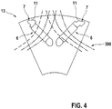
- Figure 4 finally shows a view of the stacked rotor body.
- the whole Figures 2, 3 and 4th each show only a section of a rotor pole 13 of the entire rotor 1.
- the magnet pockets 5 divide the rotor pole 13 into a radially inner pole region X and a radially outer pole region Y.
- the radially inner pole region X and the radially outer pole region Y are connected by connecting webs between the magnet pockets 5 and / or between the magnet pocket 5 and the outer circumference of the rotor 1 .
- Those connecting webs that lie between the magnet pocket 5 and the outer circumference of the rotor 1 are edge webs 11.
- the edge webs 11 are formed in particular by the contour of the edge regions 7 of the magnet pockets that abut the edge webs 11.
- the individual sheets 4 each comprise identically designed central areas 6, in which the permanent magnets 8 can be attached.
- section of the contour are on the edge webs 11 adjacent edge regions 7 of the magnet pockets 5 are displaced in the circumferential direction 100 along a line running through the edge region 7. Different magnetic fluxes 300 can thus be realized in particular.
- Figure 3 shows that the rotor laminated cores 3 are stacked to form the rotor body in such a way that a repeating pattern results from different edge regions 7 resting on the edge webs 11.
- contour sections of these edge regions 7 are displaced along the circumferential direction 100.
- adjacent rotor laminated cores 3 have edge regions 7 which abut the edge webs 11 and which are not in alignment.
- a minimal web height h remains (cf. Figure 2 ) identical for all edge webs 11.
- a smallest cross section, on which the edge webs 11 have the minimum web height h is not arranged at identical positions in the circumferential direction in the case of adjacent rotor laminated cores 3.
- Figure 3 is also shown schematically which line contour of the field lines of the magnetic flux 300 Figure 4 which rotor laminated core 3 from Figure 3 is to be assigned.
- Figure 4 it can be seen how the edge regions 7 resting on the edge webs 11 can be used to control the magnetic flux 300 of the electric motor 2.
- a result can thus be achieved which has the same effect as the inclined position of the permanent magnets 8, which is known from the prior art.
- this ensures that the individual rotor poles 13 do not all influence the influence of the stator field at the same time reach.
Abstract
Die vorliegende Erfindung betrifft einen Rotor (1) eines Elektromotors (2) umfassend einen Rotorkörper (12) mit mehreren Rotorblechpaketen (3), die jeweils eine Vielzahl von gestapelten Einzelblechen (4) aufweisen, wobei der Rotorkörper (12) eine Vielzahl von Rotorpolen (13) aufweist, wobei jeder Rotorpol (13) zumindest eine Magnettasche (5) zum Aufnehmen zumindest eines Permanentmagneten (8) aufweist, wobei die Magnettasche (5) den jeweiligen Rotorpol (13) in Radialbereiche (X, Y) unterteilt, wobei die Radialbereiche (X, Y) über Verbindungsstege miteinander verbunden sind, wobei jeder Verbindungssteg zwischen der Magnettasche (5) und dem Außenumfang des Rotors (1) ein Randsteg (11) ist, wobei die Magnettaschen (5) jeweils einen Zentralbereich (6) zur Aufnahme des Permanentmagneten (8) und beidseitig des Zentralbereichs (6) jeweils einen magnetisch nichtleitenden Randbereich (7) zur Verminderung von Streuflüssen aufweist, dadurch gekennzeichnet, dass bezüglich eines der Rotorpole (13) die Kontur des an dem Randsteg (11) anliegenden Randbereichs (7) der Magnettasche (5) von einem der Rotorblechpakete (3) zu einem jeweils benachbarten Rotorblechpaket (3) derart in Umfangsrichtung (100) verändert ist, dass der durch den Permanentmagnet (8) fließende Magnetfluss (300) von dem Rotorblechpaket (3) zu dem benachbarten Rotorblechpaket (3) in Umfangsrichtung (100) verschoben ist.The invention relates to a rotor (1) of an electric motor (2) comprising a rotor body (12) with a plurality of rotor laminations (3), each of which has a plurality of stacked individual laminations (4), the rotor body (12) having a multiplicity of rotor poles ( 13), each rotor pole (13) having at least one magnet pocket (5) for receiving at least one permanent magnet (8), the magnet pocket (5) dividing the respective rotor pole (13) into radial regions (X, Y), the radial regions (X, Y) are connected to one another via connecting webs, each connecting web between the magnet pocket (5) and the outer circumference of the rotor (1) being an edge web (11), the magnet pockets (5) each having a central area (6) for receiving the Permanent magnet (8) and on both sides of the central region (6) each have a magnetically non-conductive edge region (7) for reducing stray flux, characterized in that with respect to one of the rotor poles (13) the contour of the edge region (7) of the magnet pocket (5) resting on the edge web (11) is changed in the circumferential direction (100) from one of the rotor laminated cores (3) to an adjacent rotor laminated core (3) in such a way that the permanent magnet (8 ) flowing magnetic flux (300) is shifted from the rotor core (3) to the adjacent rotor core (3) in the circumferential direction (100).
Description
Die vorliegende Erfindung betrifft einen Rotor eines Elektromotors. Außerdem betrifft die Erfindung einen Elektromotor, umfassend einen derartigen Rotor.The present invention relates to a rotor of an electric motor. The invention also relates to an electric motor comprising such a rotor.
Aus dem Stand der Technik sind Elektromotoren bekannt. Auch ist das Problem von Rastmomenten bei Elektromotoren bekannt. Um einen rastfreien Lauf zu gewährleisten, wird bei permanent erregten Elektromotoren entweder der Stator oder der Rotor geschrägt aufgebaut. Dabei wird der magnetische Fluss über die axiale Länge des Rotors oder Stators um mehrere Winkelgrade verschoben. Somit kommen die einzelnen Pole nicht gleichzeitig in den Einfluss des Statorfelds. Ein solcher geschrägter Aufbau ist beispielsweise aus der
Erfindungsgemäß wird der Fluss innerhalb des Elektromotors nicht durch den Versatz der Magnete wie im Stand der Technik gesteuert, sondern über eine Form des Blechschnitts des Rotorblechpakets des Rotors des Elektromotors. Somit ist insbesondere vermeidbar, dass Magnete verschoben aufeinanderstoßen, wie dies im Stand der Technik der Fall ist. In diesen Bereichen gibt es die Leistung senkende 3D-Magnetkreise, die mit der Erfindung wegfallen. Außerdem ist eine Magnetisierung der Magnete im übersättigten Bereich vereinfacht und insbesondere auch vervollständigt, da die Magnetisierung an derselben Position erfolgt. Durch den Wegfall der abschnittsweisen Schrägung der Anordnung der Permanentmagnete lassen sich größere Bereiche des Rotors als Paket herstellen, insbesondere auch der ganze Rotor. Damit sinken Handlings-Kosten und die Gesamthöhentoleranz verbessert sich erheblich.According to the invention, the flow within the electric motor is not controlled by the offset of the magnets as in the prior art, but by a shape of the sheet metal cut of the rotor laminated core of the rotor of the electric motor. It is thus in particular avoidable that magnets collide in a displaced manner, as is the case in the prior art. In these areas, there are the power-reducing 3D magnetic circuits that are eliminated with the invention. In addition, magnetization of the magnets in the oversaturated region is simplified and in particular also completed, since the magnetization takes place in the same position. By eliminating the section-by-section inclination of the arrangement of the permanent magnets, larger areas of the rotor can be produced as a package, in particular the entire rotor. This reduces handling costs and the overall height tolerance improves considerably.
Insbesondere aufgrund durchgängiger Magnettaschen und dadurch mehr Magnetmasse im Rotor lässt sich die Leistung derselben E-Maschine und/oder desselben Elektromotors erhöhen. Schrägungstoleranzen zwischen den Einzelblechen des Rotorblechpakets fallen weg. Auch steigt der Freiheitsgrad bei der Realisierung der Schrägungseffekte, da unterschiedliche Einzelbleche beliebig miteinander zusammengestellt werden können. Insgesamt ist eine Reduzierung der Gesamtlänge des Rotors möglich. Außerdem ist keine Ausrichtungskerbe am Rotor für die Schrägung notwendig, insbesondere ist kein komplizierter Prozess zum Schrägen wie im Stand der Technik notwendig. Die Magnete sind also erfindungsgemäß alle gleichzeitig axial verfügbar.The performance of the same electric machine and / or the same electric motor can be increased, in particular due to the continuous magnetic pockets and thus more magnetic mass in the rotor. Bevel tolerances between the individual laminations of the rotor laminated core are eliminated. The degree of freedom in realizing the bevel effects also increases, since different individual sheets can be combined with one another as desired. Overall, a reduction in the overall length of the rotor is possible. In addition, no alignment notch on the rotor is required for the bevel, in particular, no complicated process for beveling is necessary as in the prior art. According to the invention, the magnets are all axially available at the same time.
Der erfindungsgemäße Rotor eines Elektromotors umfasst einen Rotorkörper mit mehreren Rotorblechpaketen, die jeweils eine Vielzahl von gestapelten Einzelblechen aufweisen. Der Rotorkörper weist außerdem eine Vielzahl von Rotorpolen auf. Jeder Rotorpol wiederum weist zumindest eine Magnettasche auf. Die Magnettaschen sind insbesondere als schlitzförmige Ausnehmungen in den Einzelblechen gefertigt und dienen zum Aufnehmen eines Permanentmagneten.The rotor of an electric motor according to the invention comprises a rotor body with a plurality of rotor laminated cores, each of which has a multiplicity of stacked individual laminations. The rotor body also has a plurality of rotor poles. Each rotor pole in turn has at least one magnetic pocket. The magnet pockets are in particular made as slot-shaped recesses in the individual sheets and serve to hold a permanent magnet.
Jede Magnettasche unterteilt den jeweiligen Rotorpol in Radialbereiche. Dadurch sind zumindest ein radial äußerer Polbereich und ein radial innerer Polbereich vorhanden. Die Radialbereiche sind über Verbindungsstege miteinander verbunden. Die Verbindungsstege sind insbesondere durch Bereiche zwischen zwei Magnettaschen und/oder durch Bereiche zwischen Magnettasche und Luftspalt realisiert.Each magnet pocket divides the respective rotor pole into radial areas. As a result, at least one radially outer pole region and one radially inner pole region are present. The radial areas are connected to one another via connecting webs. The connecting webs are realized in particular by areas between two magnetic pockets and / or by areas between the magnetic pocket and the air gap.
Dabei ist vorgesehen, dass die Magnettaschen einen Zentralbereich und beidseitig an den Zentralbereich anschließende Randbereiche aufweisen. Es ist vorgesehen, dass die Permanentmagnete nur an den Zentralbereichen der Magnettaschen vorhanden sind. Dabei sind die Permanentmagnete bevorzugt optimal zueinander angeordnet, so dass parasitäre 3D-Magnetkreise wie im Stand der Technik vermieden sind. Die Randbereiche der Magnettaschen sind vorteilhafterweise frei von Permanentmagneten. Somit dienen die zweiten Magnettaschen ausschließlich zum Steuern des Flusses innerhalb des Elektromotors, nicht jedoch zur Aufnahme von Permanentmagneten.It is provided that the magnetic pockets have a central region and edge regions adjoining the central region on both sides. It is provided that the permanent magnets are only present on the central areas of the magnet pockets. The permanent magnets are preferably optimally arranged with respect to one another, so that parasitic 3D magnetic circuits as in the prior art are avoided. The edge areas of the magnet pockets are advantageously free of permanent magnets. Thus, the second magnet pockets are used exclusively to control the flow within the electric motor, but not to hold permanent magnets.
Der Randbereich umfasst somit einen radial äußersten Bereich der Magnettaschen. Dadurch ist ein Verbindungssteg definiert, der ein Randsteg zwischen Magnettasche und Luftspalt ist. Der Luftspalt ist insbesondere zwischen der Außenumfangsfläche des Rotors und einem Stator des Elektromotors definiert. Durch die entsprechende Ausgestaltung des radial äußersten Bereichs der Magnettasche lässt sich der magnetische Fluss innerhalb des Elektromotors einstellen.The edge area thus comprises a radially outermost area of the magnet pockets. This defines a connecting web, which is an edge web between the magnet pocket and the air gap. The air gap is defined in particular between the outer peripheral surface of the rotor and a stator of the electric motor. The magnetic flux within the electric motor can be adjusted by the corresponding configuration of the radially outermost region of the magnet pocket.
Bezüglich eines der Rotorpole ist die Kontur des an dem Randsteg anliegenden Randbereichs der Magnettasche von einem der Rotorblechpakete zu einem jeweils benachbarten Rotorblechpaket derart in Umfangsrichtung verändert, dass der durch den Permanentmagnet fließende Magnetfluss von dem Rotorblechpaket zu dem benachbarten Rotorblechpaket in Umfangsrichtung verschoben ist. Somit erfolgt eine Steuerung des Flusses innerhalb des Elektromotors durch die unterschiedliche Ausbildung der radial äußeren Randbereiche der einzelnen Rotorblechpakete. Bezüglich der d-Achse des Rotors ist somit bevorzugt ein symmetrischer Magnetfluss in einem Teil der Rotorblechpakete erreicht, während bei anderen Rotorblechpaketen der Magnetfluss bezüglich der d-Achse entweder nach links oder nach rechts verschoben ist. Dadurch wird der Magnetfluss variiert. Dies führt zu einer Rastmomentunterdrückung und einem gleichmäßigen Drehmomentverlauf. Insbesondere werden dieselben Effekte erreicht, wie bei der aus dem Stand der Technik bekannten Rotorschrägstellung, wobei die Herstellung und Montage des Rotors erheblich vereinfacht ist.With respect to one of the rotor poles, the contour of the edge region of the magnet pocket resting on the edge web is changed in the circumferential direction from one of the rotor laminated cores to an adjacent rotor laminated core such that the magnetic flux flowing through the permanent magnet is shifted in the circumferential direction from the rotor laminated core to the adjacent rotor laminated core. The flow within the electric motor is thus controlled by the different design of the radially outer edge regions of the individual rotor laminated cores. With respect to the d-axis of the rotor, a symmetrical magnetic flux is thus preferably achieved in part of the rotor laminated cores, while in other rotor laminated cores the magnetic flux is either shifted to the left or to the right with respect to the d-axis. This varies the magnetic flux. This leads to a cogging torque suppression and an even torque curve. In particular, the same effects are achieved as in the case of the rotor inclination known from the prior art, the manufacture and assembly of the rotor being considerably simplified.
Bei allen Rotorblechpaketen sind die Zentralbereiche der Magnettaschen bevorzugt fluchtend ausgebildet. Dadurch ist eine Montage der Permanentmagnete einfach und aufwandsarm ermöglicht. Zumindest die radial äußeren Randbereiche, die an den Randstegen anliegen, sind besonders vorteilhaft zumindest teilweise gegeneinander versetzt. Somit ist insbesondere erreicht, dass die einzelnen Einzelbleche des Rotorblechpakets die Randbereiche von anderen Einzelblechen des Rotorblechpakets zumindest teilweise verdecken. Die Magnettaschen der Einzelbleche an den Randbereichen sind somit nicht fluchtend angeordnet und unterscheiden sich damit von den ersten Teilbereichen. Die ersten Teilbereiche hingegen ermöglichen ein durchgängiges Anordnen der Permanentmagnete.The central areas of the magnet pockets are preferably designed to be aligned in all rotor laminated core assemblies. This enables the permanent magnets to be installed easily and with little effort. At least the radially outer edge regions which abut the edge webs are particularly advantageously at least partially offset from one another. It is thus achieved in particular that the individual individual sheets of the rotor sheet stack at least partially cover the edge regions of other individual sheets of the rotor sheet stack. The magnetic pockets of the individual sheets on the edge areas are therefore not aligned and thus differ from the first partial areas. The first sub-areas, on the other hand, allow the permanent magnets to be arranged throughout.
Die Unteransprüche haben bevorzugte Weiterbildungen der Erfindung zum Inhalt.The dependent claims contain preferred developments of the invention.
Bevorzugt ist vorgesehen, dass jeder Randsteg eines Rotorpols bezüglich der Lage seiner Enden von einem der Rotorblechpakete zu einem jeweils benachbarten Rotorblechpaket in Umfangsrichtung versetzt ist. Somit erfolgt insbesondere ein unterschiedliches Anordnen der radial äußeren Randbereiche der Magnettaschen. Dadurch lässt sich vorteilhaft das zuvor beschriebene verschieben der Magnetflüsse erreichen.It is preferably provided that each edge web of a rotor pole is offset in the circumferential direction with respect to the position of its ends from one of the rotor laminated cores to an adjacent rotor laminated core. In particular, the radially outer edge regions of the magnet pockets are thus arranged differently. The shifting of the magnetic fluxes described above can thereby advantageously be achieved.
Vorteilhafterweise weist jeder Randsteg jeweils einen engsten Querschnitt auf. Die engsten Querschnitte aller Randstege eines Rotorpols sind insbesondere von einem der Rotorblechpakete zu einem jeweils benachbarten Rotorblechpaket in Umfangsrichtung versetzt. Somit ist der durch den Permanentmagnet fließende Magnetfluss verschoben, wobei die Einzelbleche des Rotorblechpakets einfach und aufwandsarm herstellbar sind.Each edge web advantageously has the narrowest cross section. The narrowest cross-sections of all edge webs of a rotor pole are offset in particular in the circumferential direction from one of the rotor laminated cores to an adjacent rotor laminated core. The magnetic flux flowing through the permanent magnet is thus shifted, the individual laminations of the rotor laminated core being simple and inexpensive to produce.
Bezüglich eines der Rotorpole ist die Kontur des an dem Randsteg anliegenden Randbereichs der Magnettasche über alle Rotorblechpakete bevorzugt derart in Umfangsrichtung verändert, dass der durch die Permanentmagnete fließende Magnetfluss über alle Rotorblechpakete gesehen zunehmend in Umfangsrichtung verschoben ist. Dadurch ist das Auftreten von Rastmomenten verringert, wodurch ein gleichmäßiger Drehmomentverlauf erreichbar ist.With respect to one of the rotor poles, the contour of the edge region of the magnet pocket resting on the edge web is preferably changed in the circumferential direction over all rotor laminated cores in such a way that the magnetic flux flowing through the permanent magnets is increasingly shifted in the circumferential direction as seen across all rotor laminated cores. As a result, the occurrence of cogging torques is reduced, as a result of which a uniform torque curve can be achieved.
Bevorzugt ist ein Abschnitt der Kontur der an den Randstegen anliegenden Randbereichen der Magnettaschen in Umfangsrichtung entlang einer durch den Randbereich verlaufenden Linie verschoben ist. Somit ist ein gleichmäßiger Aufbau der Einzelbleche der Rotorblechpakete erreicht. Insbesondere ist lediglich ein Teil des äußeren Randbereichs jeder Magnettasche verschoben ausgebildet. Somit ist insbesondere erreicht, dass jedes Einzelblech gleich große Magnettaschen aufweist, die sich lediglich in ihrer Form unterscheiden.A section of the contour of the edge regions of the magnet pockets lying against the edge webs is preferably shifted in the circumferential direction along a line running through the edge region. A uniform structure of the individual laminations of the rotor laminated cores is thus achieved. In particular, only a part of the outer edge region of each magnet pocket is designed to be displaced. It is thus achieved in particular that each individual sheet has magnet pockets of the same size, which differ only in their shape.
Die Permanentmagnete sind vorteilhafterweise V-förmig und/oder C-förmig angeordnet. Somit sind die Magnettaschen insbesondere in Lagen angeordnet, wobei jede Lage eine V-förmige oder C-förmige Anordnung bildet. Beispielsweise weist der Rotor einlagige C-Magnetanordnungen oder V-Magnetanordnungen an Permanentmagneten auf. Ebenso kann der Rotor mehrlagige VC-W-Anordnungen oder CC-Anordnungen umfassen. In jedem Fall wird durch die Randbereiche ein Fluss des Elektromotors optimal eingestellt.The permanent magnets are advantageously arranged in a V-shape and / or a C-shape. Thus, the magnetic pockets are arranged in particular in layers, each layer forming a V-shaped or C-shaped arrangement. For example, the rotor has single-layer C-magnet arrangements or V-magnet arrangements on permanent magnets. The rotor can also have multi-layer VC-W arrangements or CC arrangements. In any case, a flow of the electric motor is optimally set by the edge regions.
Besonders vorteilhaft weist der Rotorkörper mehrere verschiedene Rotorblechpakete auf. Die Rotorblechpakete umfassen jeweils identische Einzelbleche. Die Einzelbleche verschiedener Rotorblechpakete weisen unterschiedliche an den jeweiligen Randstegen anliegende Randbereiche auf. Dabei erfolgt eine Stapelung der Einzelbleche zu dem Rotorblechpaket derart, dass eine Stapelfolge der Einzelbleche ein sich wiederholendes Muster an verschiedenen Randbereichen aufweist. Somit ist insbesondere erreichbar, dass sich unmittelbar benachbarte Einzelbleche in ihren Randbereichen unterscheiden, die an den jeweiligen Randstegen anliegen. Durch das sich wiederholende Muster hingegen ist erreichbar, dass die Anzahl der unterschiedlichen Einzelbleche begrenzt ist. Somit ist einerseits eine sichere und zuverlässige Steuerung des Magnetflusses ermöglicht, andererseits ist ein Aufbau des Rotorblechpakets des Elektromotors nicht aufwendig zu fertigen.The rotor body particularly advantageously has a plurality of different rotor laminated cores. The rotor laminated cores each comprise identical individual laminations. The individual laminations of different rotor laminated cores have different marginal areas lying against the respective edge webs. The individual sheets are stacked to form the rotor laminated core in such a way that a stacking sequence of the individual sheets has a repeating pattern at different edge regions. It can thus be achieved, in particular, that immediately adjacent individual sheets differ in their edge regions, which lie against the respective edge webs. However, the repeating pattern means that the number of different individual sheets is limited. Thus, on the one hand, a safe and reliable control of the magnetic flux is made possible, on the other hand, it is not complex to assemble the rotor laminated core of the electric motor.
Besonders vorteilhaft weist jedes Muster einen zunehmenden Versatz der an dem Randsteg anliegenden Randbereiche in eine Umfangsrichtung des Rotors auf. Somit ist ein äquivalent zu der Schrägung im Stand der Technik erreicht. Durch den zunehmenden Versatz ist jedes Muster einfach und aufwandsarm herstellbar, da lediglich ein minimaler Versatz, ein maximaler Versatz und die Anzahl von Einzelblechen mit einem Versatz zwischen dem minimalen Versatz und dem maximalen Versatz festgelegt werden müssen. Somit ist einerseits ein detailliertes Einstellen des Flusses des Elektromotors ermöglicht, andererseits ist der Rotor einfach und aufwandsarm herstellbar.Each pattern particularly advantageously has an increasing offset in a peripheral direction of the rotor of the edge regions abutting the edge web. An equivalent to the skew is thus achieved in the prior art. Due to the increasing offset, each pattern can be produced easily and with little effort, since only a minimum offset, a maximum offset and the number of individual sheets with an offset between the minimum offset and the maximum offset need to be determined. Thus, on the one hand, a detailed adjustment of the flow of the electric motor is made possible, on the other hand, the rotor can be manufactured easily and with little effort.
Vorteilhafterweise erstrecken sich die Magnettaschen der durch das alle Rotorblechpakete. Dies gilt vorteilhafterweise für die Zentralbereiche der Magnettaschen. Somit ist eine durchgängige Öffnung in dem Rotorkörper vorhanden, die sich durch den gesamten Rotor zieht. Somit lassen sich Permanentmagnete entlang der gesamten axialen Länge des Rotors platzieren. Damit wird eine optimale Magnetmasse des Rotors sichergestellt.Advantageously, the magnetic pockets extend through all the rotor laminations. This advantageously applies to the central areas of the magnetic pockets. There is thus a continuous opening in the rotor body which extends through the entire rotor. Permanent magnets can thus be placed along the entire axial length of the rotor. This ensures an optimal magnetic mass of the rotor.
Besonders vorteilhaft ist vorgesehen, dass eine minimale Steghöhe bei allen Randstegen identisch ist. Insbesondere weist jeder Randsteg eine unterschiedliche Höhe über die Magnettaschen auf. Dabei ist der Verlauf dieser unterschiedlichen Höhe bei allen Randstegen vorteilhafterweise identisch. Auf diese Weise lässt sich der magnetische Fluss innerhalb des Elektromotors optimal einstellen, ohne andere Parameter des Rotors oder des Elektromotors negativ zu beeinflussen.It is particularly advantageously provided that a minimum web height is identical for all edge webs. In particular, each edge web has a different height above the magnetic pockets. The course of this is different heights advantageously identical for all edge webs. In this way, the magnetic flux within the electric motor can be optimally adjusted without negatively influencing other parameters of the rotor or the electric motor.
Die Erfindung betrifft schließlich einen Elektromotor. Der Elektromotor umfasst einen Rotor wie zuvor beschrieben. Dabei ist vorgesehen, dass der Rotor von einem Stator des Elektromotors angetrieben wird. Durch die zuvor beschriebene Anordnung der Randbereiche der Magnettaschen des Rotors ist ein Fluss innerhalb des Elektromotors optimiert. Gleichzeitig lassen sich Permanentmagnete des Rotors einfach und aufwandsarm anbringen.Finally, the invention relates to an electric motor. The electric motor includes a rotor as previously described. It is provided that the rotor is driven by a stator of the electric motor. A flow within the electric motor is optimized by the arrangement of the edge areas of the magnet pockets of the rotor described above. At the same time, permanent magnets of the rotor can be attached easily and with little effort.
Die Magnettaschen und/oder die Einzelbleche sind insbesondere durch Stanzen hergestellt. Somit lassen sich die Kontur der Einzelbleche sowie die Kontur der Magnettaschen einfach und kostengünstig herstellen. Dies gilt insbesondere für die unterschiedlichen Randbereiche, da hier lediglich verschiedene Stanzwerkzeuge bereitgestellt werden müssen. Somit lassen sich die Einzelbleche in hoher Stückzahl einfach und aufwandsarm herstellen.The magnetic pockets and / or the individual sheets are produced in particular by stamping. The contour of the individual sheets and the contour of the magnetic pockets can thus be produced simply and inexpensively. This applies in particular to the different edge areas, since only different punching tools have to be provided here. This means that the individual sheets can be produced in large numbers easily and with little effort.
Vorteilhafterweise sind die Randbereiche von Magnettaschen von in dem Rotorkörper benachbart angeordneten Rotorblechpaketen mit jeweils identischen Einzelblechen in Umfangsrichtung des Rotors verschoben. Somit ist insbesondere vorgesehen, dass die Randbereiche von zwei benachbarten Rotorblechpaketen nicht fluchtend angeordnet sind, sondern vielmehr einen Versatz aufweisen. Dabei kann vorgesehen sein, dass zwei nicht unmittelbar benachbarte Rotorblechpakete identische Magnettaschen aufweisen. Somit ist einerseits eine Steuerung des Flusses des Elektromotors ermöglicht, andererseits ist ein Herstellungsaufwand reduziert, da nicht für den gesamten Rotorkörper individuelle Einzelbleche oder Rotorblechpakete hergestellt werden müssen.Advantageously, the edge areas of magnet pockets of rotor laminated cores arranged adjacent in the rotor body, each with identical individual laminations, are displaced in the circumferential direction of the rotor. It is thus provided in particular that the edge regions of two adjacent rotor laminated cores are not arranged in alignment, but rather have an offset. It can be provided that two not directly adjacent rotor laminated cores have identical magnetic pockets. Thus, on the one hand, control of the flow of the electric motor is made possible, and on the other hand, manufacturing expenditure is reduced, since it is not necessary to produce individual individual laminations or laminated cores for the entire rotor body.
Nachfolgend werden Ausführungsbeispiele der Erfindung unter Bezugnahme auf die begleitende Zeichnung im Detail beschrieben. In der Zeichnung ist:
- Figur 1
- eine schematische Abbildung eines Elektromotors gemäß einem Ausführungsbeispiel der Erfindung,
Figur 2- eine schematische Ansicht mehrerer Einzelbleche eines Rotors gemäß einem Ausführungsbeispiel der Erfindung,
Figur 3- eine schematische Explosionsdarstellung gestapelter Rotorblechpakete des Rotors gemäß dem Ausführungsbeispiel der Erfindung, und
Figur 4- eine schematische Ansicht des Rotors gemäß dem Ausführungsbeispiel der Erfindung.
- Figure 1
- 1 shows a schematic illustration of an electric motor according to an exemplary embodiment of the invention,
- Figure 2
- 2 shows a schematic view of several individual sheets of a rotor according to an embodiment of the invention,
- Figure 3
- a schematic exploded view of stacked rotor laminations of the rotor according to the embodiment of the invention, and
- Figure 4
- is a schematic view of the rotor according to the embodiment of the invention.
Der Rotor 1 umfasst mehrere Rotorblechpakete 3, die gemeinsam einen Rotorkörper 12 formen, der auf einer Welle 9 angebracht ist. Somit können die Rotorblechpakete 3 rotiert werden. Jedes Rotorblechpaket 3 wiederum umfasst eine Vielzahl von identischen Einzelblechen 4, die zum jeweiligen Rotorblechpaket 3 gestapelt sind. Die Einzelbleche 4 sind vorteilhafterweise aus einem Elektroblech hergestellt, insbesondere durch Stanzen. In
Jedes Einzelblech 4 umfasst mehrere Ausnehmungen, sodass die Rotorblechpakete 3 Magnettaschen 5 bilden. Die Magnettaschen 5 weisen einen Zentralbereich 6 und beidseitig daran anschließende Randbereiche 7 auf, wobei Zentralbereich 6 und Randbereiche 7 unmittelbar aneinander anstoßen und nicht voneinander abgegrenzt sind. Im Folgenden werden stets die radial äußeren Randbereiche beschrieben.Each
Werden die Rotorblechpakete 3 zu dem Rotorkörper gestapelt, so ist vorgesehen, dass sämtliche Zentralbereiche 6 der Magnettaschen 5 fluchtend angeordnet werden. Dies bedeutet, dass die Zentralbereiche 6 bezüglich einer Radialrichtung 200 und bezüglich einer Umfangsrichtung 100 stets an demselben Bereich des Rotors 2 angeordnet sind. Somit entsteht eine durchgängige Öffnung, die sich insbesondere über eine gesamte Länge des Rotors 1 erstreckt. In diese Öffnung lassen sich Permanentmagnete 8 einbringen.If the rotor laminated
Die Randbereiche 7 der Magnettaschen 5 sind insbesondere derart geformt, dass der durch den Permanentmagneten 8 verlaufende Magnetfluss bei benachbarten Rotorblechpaketen 3 in Umfangsrichtung 100 verschoben ist. In diesen Randbereichen 7 sind keinerlei Permanentmagnete 8 vorhanden, so dass sämtliche Randbereiche 7 frei von Permanentmagneten 8 sind. Die Form der Randbereiche 7 dient lediglich zum Steuern des Magnetflusses 300. Dies wird nachfolgend mit Bezug auf
Die Magnettaschen 5 teilen den Rotorpol 13 in einen radial inneren Polbereich X und einen radial äußeren Polbereich Y. Der radial innere Polbereich X und der radial äußere Polbereich Y sind durch Verbindungsstege zwischen den Magnettaschen 5 und/oder zwischen Magnettasche 5 und Außenumfang des Rotors 1 verbunden. Diejenigen Verbindungsstege, die zwischen Magnettasche 5 und Außenumfang des Rotors 1 liegen, sind Randstege 11. Die Randstege 11 werden insbesondere durch die Kontur der an den Randstegen 11 anliegenden Randbereiche 7 der Magnettaschen geformt.The magnet pockets 5 divide the
Wie aus
In
Durch das Verschieben des Magnetflusses 300 bei benachbarten Rotorblechpaketen 3 wird somit erreicht, dass die Rastmomente des Elektromotors 2 minimiert sind. Gleichzeitig verbleibt eine durchgängige Öffnung durch alle Rotorblechpakete 3, in die die Permanentmagneten 8 einfach und aufwandsarm eingesetzt werden können. Somit ist ein Aufbau des Elektromotors 2, insbesondere des Rotors 1, vereinfacht. Auch lässt sich die Magnetmasse innerhalb des Rotors 1 im Vergleich zum Stand der Technik erhöhen. Schließlich wird vermieden, dass innerhalb des Rotors 1 Magnete gegeneinander verschoben sind, so dass insbesondere das Auftreten von parasitären 3D-Magnetkreisen verhindert wird.By shifting the
Claims (11)
Applications Claiming Priority (1)
| Application Number | Priority Date | Filing Date | Title |
|---|---|---|---|
| DE102018220057.2A DE102018220057A1 (en) | 2018-11-22 | 2018-11-22 | Rotor of an electric motor and electric motor |
Publications (1)
| Publication Number | Publication Date |
|---|---|
| EP3657638A1 true EP3657638A1 (en) | 2020-05-27 |
Family
ID=68281146
Family Applications (1)
| Application Number | Title | Priority Date | Filing Date |
|---|---|---|---|
| EP19203516.0A Withdrawn EP3657638A1 (en) | 2018-11-22 | 2019-10-16 | Rotor of an electric motor and electric motor |
Country Status (2)
| Country | Link |
|---|---|
| EP (1) | EP3657638A1 (en) |
| DE (1) | DE102018220057A1 (en) |
Cited By (1)
| Publication number | Priority date | Publication date | Assignee | Title |
|---|---|---|---|---|
| EP4366138A1 (en) * | 2022-11-04 | 2024-05-08 | Huawei Digital Power Technologies Co., Ltd. | Rotor and permanent magnet motor |
Citations (2)
| Publication number | Priority date | Publication date | Assignee | Title |
|---|---|---|---|---|
| DE102014019218A1 (en) | 2014-12-19 | 2015-06-25 | Daimler Ag | Sheet metal package for an electric machine |
| WO2018188755A1 (en) * | 2017-04-13 | 2018-10-18 | Abb Schweiz Ag | Sheet and rotor of electric machine and method of manufacturing them |
-
2018
- 2018-11-22 DE DE102018220057.2A patent/DE102018220057A1/en not_active Withdrawn
-
2019
- 2019-10-16 EP EP19203516.0A patent/EP3657638A1/en not_active Withdrawn
Patent Citations (2)
| Publication number | Priority date | Publication date | Assignee | Title |
|---|---|---|---|---|
| DE102014019218A1 (en) | 2014-12-19 | 2015-06-25 | Daimler Ag | Sheet metal package for an electric machine |
| WO2018188755A1 (en) * | 2017-04-13 | 2018-10-18 | Abb Schweiz Ag | Sheet and rotor of electric machine and method of manufacturing them |
Cited By (1)
| Publication number | Priority date | Publication date | Assignee | Title |
|---|---|---|---|---|
| EP4366138A1 (en) * | 2022-11-04 | 2024-05-08 | Huawei Digital Power Technologies Co., Ltd. | Rotor and permanent magnet motor |
Also Published As
| Publication number | Publication date |
|---|---|
| DE102018220057A1 (en) | 2020-05-28 |
Similar Documents
| Publication | Publication Date | Title |
|---|---|---|
| EP3189582B1 (en) | Rotor for an electric machine, electric machine and method for producing a rotor of an electric machine. | |
| DE112007000201T5 (en) | Slotted cores for a motor stator, motor stator, permanent magnet type synchronous motor, and punch punch punching method for slotted cores | |
| EP2378627A1 (en) | Electric motor | |
| EP2903136A1 (en) | Reluctance rotor sheet with a recess for reducing stress | |
| DE10227859A1 (en) | Induction motor of the type with embedded permanent magnet, which allows the coil to be embedded easily | |
| DE10247187A1 (en) | Stator tooth for stator core e.g. of brushless permanent magnet motor, has tooth surface with one or more flat segments extending from one end of first edge formed by slot opening to end of second edge | |
| DE102012022084A1 (en) | Rotor assembly for electrical machine, has laminated plate stacks having positioning units positioned at axial end surfaces in juxtaposition at joining of two axially adjacent laminated plate stacks | |
| DE102017102242A1 (en) | USE OF MAGNETIC FIELDS IN ELECTRIC MACHINES | |
| DE102013200476A1 (en) | Permanent magnet-excited two-pole synchronous machine e.g. wind force generator, for use as inner rotor machine in wind-power plant, has pockets comprising magnets that exhibits magnetization direction to form magnetic poles of rotor | |
| EP3381107B1 (en) | Electrical sheet having printed web | |
| EP2942858B1 (en) | Laminated rotor core | |
| EP2479872B1 (en) | Permanently excited synchronous machine with a rotor | |
| DE2416610A1 (en) | PERMANENT MAGNET SYNCHRONOUS MOTOR | |
| WO2013053479A1 (en) | Rotor core stack, rotor and method for producing a rotor core stack | |
| EP1964240A1 (en) | Rotor of an electrical machine, in particular of a motor, and method for producing a rotor | |
| EP3742583A1 (en) | Quadrupole synchronous reluctance machine | |
| DE102009019555A1 (en) | Iron core i.e. stator core, for electrical machine e.g. direct current motor, has multiple sheets stacked and rotated against each other around integral multiple of pole distance, and partial pole shoes formed in convex and concave shape | |
| EP3657638A1 (en) | Rotor of an electric motor and electric motor | |
| DE102017204401A1 (en) | Segmented stator for one or in an axial flow machine | |
| WO2016162137A1 (en) | Rotor arrangement for an electric machine | |
| DE102005062922A1 (en) | Electromotor, has stator, which generates by supplying current for coil of rotating magnetic field, and permanent magnets are placed in slots, and periphery slot segments has smaller width than radial slot segments | |
| WO2021148088A1 (en) | Rotor, method for producing a rotor and electrical axial flux machine | |
| DE102020114008A1 (en) | Set of laminated cores and rotor with set of laminated cores attached to the rotor shaft | |
| DE102020101148A1 (en) | Axial flux machine with radially extending sheet metal segments having stator | |
| DE102013218769A1 (en) | Rotor and method of manufacturing a rotor |
Legal Events
| Date | Code | Title | Description |
|---|---|---|---|
| PUAI | Public reference made under article 153(3) epc to a published international application that has entered the european phase |
Free format text: ORIGINAL CODE: 0009012 |
|
| STAA | Information on the status of an ep patent application or granted ep patent |
Free format text: STATUS: THE APPLICATION HAS BEEN PUBLISHED |
|
| AK | Designated contracting states |
Kind code of ref document: A1 Designated state(s): AL AT BE BG CH CY CZ DE DK EE ES FI FR GB GR HR HU IE IS IT LI LT LU LV MC MK MT NL NO PL PT RO RS SE SI SK SM TR |
|
| AX | Request for extension of the european patent |
Extension state: BA ME |
|
| STAA | Information on the status of an ep patent application or granted ep patent |
Free format text: STATUS: THE APPLICATION IS DEEMED TO BE WITHDRAWN |
|
| 18D | Application deemed to be withdrawn |
Effective date: 20201128 |