EP3657055A1 - Vanne de liquide - Google Patents
Vanne de liquide Download PDFInfo
- Publication number
- EP3657055A1 EP3657055A1 EP18461627.4A EP18461627A EP3657055A1 EP 3657055 A1 EP3657055 A1 EP 3657055A1 EP 18461627 A EP18461627 A EP 18461627A EP 3657055 A1 EP3657055 A1 EP 3657055A1
- Authority
- EP
- European Patent Office
- Prior art keywords
- valve
- fluid
- valve body
- valve housing
- inlet
- Prior art date
- Legal status (The legal status is an assumption and is not a legal conclusion. Google has not performed a legal analysis and makes no representation as to the accuracy of the status listed.)
- Pending
Links
Images


Classifications
-
- F—MECHANICAL ENGINEERING; LIGHTING; HEATING; WEAPONS; BLASTING
- F16—ENGINEERING ELEMENTS AND UNITS; GENERAL MEASURES FOR PRODUCING AND MAINTAINING EFFECTIVE FUNCTIONING OF MACHINES OR INSTALLATIONS; THERMAL INSULATION IN GENERAL
- F16K—VALVES; TAPS; COCKS; ACTUATING-FLOATS; DEVICES FOR VENTING OR AERATING
- F16K11/00—Multiple-way valves, e.g. mixing valves; Pipe fittings incorporating such valves
- F16K11/02—Multiple-way valves, e.g. mixing valves; Pipe fittings incorporating such valves with all movable sealing faces moving as one unit
- F16K11/08—Multiple-way valves, e.g. mixing valves; Pipe fittings incorporating such valves with all movable sealing faces moving as one unit comprising only taps or cocks
- F16K11/083—Multiple-way valves, e.g. mixing valves; Pipe fittings incorporating such valves with all movable sealing faces moving as one unit comprising only taps or cocks with tapered plug
- F16K11/0836—Multiple-way valves, e.g. mixing valves; Pipe fittings incorporating such valves with all movable sealing faces moving as one unit comprising only taps or cocks with tapered plug having all the connecting conduits situated in more than one plane perpendicular to the axis of the plug
-
- F—MECHANICAL ENGINEERING; LIGHTING; HEATING; WEAPONS; BLASTING
- F16—ENGINEERING ELEMENTS AND UNITS; GENERAL MEASURES FOR PRODUCING AND MAINTAINING EFFECTIVE FUNCTIONING OF MACHINES OR INSTALLATIONS; THERMAL INSULATION IN GENERAL
- F16K—VALVES; TAPS; COCKS; ACTUATING-FLOATS; DEVICES FOR VENTING OR AERATING
- F16K27/00—Construction of housing; Use of materials therefor
- F16K27/06—Construction of housing; Use of materials therefor of taps or cocks
- F16K27/062—Construction of housing; Use of materials therefor of taps or cocks with conical plugs
-
- Y—GENERAL TAGGING OF NEW TECHNOLOGICAL DEVELOPMENTS; GENERAL TAGGING OF CROSS-SECTIONAL TECHNOLOGIES SPANNING OVER SEVERAL SECTIONS OF THE IPC; TECHNICAL SUBJECTS COVERED BY FORMER USPC CROSS-REFERENCE ART COLLECTIONS [XRACs] AND DIGESTS
- Y10—TECHNICAL SUBJECTS COVERED BY FORMER USPC
- Y10T—TECHNICAL SUBJECTS COVERED BY FORMER US CLASSIFICATION
- Y10T137/00—Fluid handling
- Y10T137/8593—Systems
- Y10T137/86493—Multi-way valve unit
- Y10T137/86863—Rotary valve unit
- Y10T137/86871—Plug
Definitions
- the present disclosure relates to fluid valves, for example to three-port, three-position fluid valves.
- Fluid valves typically comprise a valve housing having inlet and outlet ports and a rotary valve body which is rotatable within the valve housing to selectively open and close ports in the valve housing and thus direct fluid between different ports or to prevent fluid flow between the ports.
- An example of such a valve is a 3-port, 3 position valve.
- the ports are spaced apart by 90 degrees, and each position change of the valve requires a 90 degree rotation of the ball element, and to cover all three rotational positions of the valve it is necessary to allow for 180 degrees of rotation in total. This large rotational movement required may limit the number of actuator types which may be used to rotate the ball element. Also, it may mean that movement of the ball element between positions may be slow.
- the disclosure provides a fluid valve comprising a valve housing having at least one fluid inlet and at least one fluid outlet and having a valve axis. At least one of the inlet and the outlet are arranged in a wall extending circumferentially about the valve axis.
- the valve further comprises a rotary valve body arranged within the valve housing for rotation about the valve axis.
- the rotary valve body comprises a frusto-conical valve body wall and at least one inlet or outlet valve body opening through the valve body wall.
- the valve body is rotatable about the valve axis so as selectively to place the valve housing inlet and valve housing outlet into fluid communication via the at least one valve body opening.
- the at least one inlet or outlet valve body opening is a slot which extends in the direction of the valve axis (A).
- the aspect ratio of the slot defined as the ratio of its axial length to circumferential width, may be at least 3:1. In some embodiments, the aspect ratio may be at least 4:1, for example at least 5:1.
- the valve may further comprise a sealing element interposed between the valve housing and the valve body wall.
- the sealing element has a frusto-conical inner surface for receiving the frusto-conical valve body wall and a sealing element opening in that wall and aligned with the valve housing inlet or outlet.
- the sealing element may comprise an open ended frusto-conical sleeve.
- the valve housing may have a frusto-conical inner surface for receiving the sealing element.
- the sealing element may be made from a low friction material, for example PTFE.
- the valve may further comprise respective cylindrical fluid connectors mounted to the at least one valve housing inlet and outlet for conducting fluid to and from the valve housing.
- the cross sectional flow area of a respective connector may be substantially the same as the cross sectional area of the corresponding valve body opening.
- the fluid connector may extend through the valve housing wall and into sealing engagement with the sealing element.
- the connector may optionally extend into a corresponding seal element opening.
- valve housing inlet may not be closable by the valve body.
- the valve housing inlet may be arranged at one axial end of the valve housing and be aligned axially of the valve housing.
- the valve may further comprise a biasing element mounted at one axial end of the valve housing for biasing the valve body axially into the valve housing and into contact with the sealing element.
- the biasing element may optionally comprise one or more annular springs.
- the biasing element may be mounted between the valve housing inlet and one end of the valve body.
- all inlets and outlets to the valve body may be in the circumferential wall of the valve body.
- the valve housing may comprise an axial opening at an end thereof.
- the opening may be aligned with a coupling on the valve body for coupling the valve body to an actuator.
- the disclosure also extends to a fluid valve assembly comprising a fluid valve as described above and an actuator coupled to the valve body for rotating the valve body.
- the actuator may, for example, be a rotary solenoid, a linear solenoid, a stepper motor, a hydraulic actuator or a pneumatic actuator.
- the fluid valve 2 comprises a valve housing 4, having a plurality of fluid connectors 6a, 6b, 6c mounted thereto.
- the connector 6a is a fluid inlet connector while the connectors 6b and 6c are fluid outlet connectors.
- the fluid inlet connector 6a may be coupled to a source of fluid and the fluid outlet connectors be coupled to systems requiring fluid.
- a rotary valve body 8 is rotationally mounted within the valve housing 4 for selectively distributing fluid entering the inlet connector 6a to the outlet connectors 6b, 6c.
- the valve housing 4 defines a longitudinal axis A about which the rotary valve body 8 rotates.
- the valve housing 4 comprises a fluid inlet 10a at its lower axial end 12, in and, in this embodiment two fluid outlets 10b, 10c.
- the fluid outlets 10b, 10c are formed in a wall 14 extending circumferentially about the valve axis A.
- the respective fluid inlets and outlets 10a, 10b, 10c are in fluid communication with the respective fluid connectors 6a, 6b, 6c.
- the lower end 12 of the valve housing 4 is closed by the inlet connector 6a.
- the rotary valve body 8 is arranged within the valve housing 4 for rotation about the valve axis A.
- the rotary valve body 8 comprises a frusto-conical valve body wall 16 which defines an internal chamber 18.
- the wall 16 may, as shown, have a constant thickness and have generally parallel inner and outer surfaces. In alternative embodiments, the thickness of the wall 16 may vary axially.
- the upper end 20 of the rotary valve body 8 is closed by a top wall 22 while the bottom end 24 of the rotary valve body 8 is open.
- An inlet opening 26 is defined in the bottom end 24 of the valve body 8.
- a plurality (in his embodiment four) outlet openings 28a, 28b, 28c, 28d are formed through the valve body wall 16 for selective rotational alignment or misalignment with the respective valve housing fluid outlets 10b, 10c to allow flow to pass from the valve housing fluid inlet 10a to the housing fluid outlets 10b, 10c via the internal chamber 18 of the valve body 8.
- the outlet openings 28a, 28b, 28c, 28d are arranged in pairs, the openings 28a, 28b being associated with the fluid outlet 10b and the openings 28c, 28d being associated with the fluid outlet 10c.
- the openings 28a, 28d are arranged along a common axis, with the openings 28b, 28c being arranged at an angle of 45 degrees from the openings 28a, 28d respectively.
- the various operational positions of the valve body 8 will be discussed further below.
- the outlet openings 28a, 28b, 28c, 28d in the frusto-conical valve body wall 16 are each formed as a slot which extends in the direction of the valve axis A.
- the aspect ratio of each slot i.e. the ratio of the slot's maximum longitudinal length L to its maximum circumferential width W is greater than 1:1.
- the aspect ratio may typically be in the range of region of 2:1 to 10:1, for example at least 3:1, for example at least 4:1, for example at least 5:1, depending on the number of outlet openings 28 which are required.
- the slots optionally have parallel side walls as shown, with optionally arcuate upper and lower ends as shown, so that they resemble an elongated oval or race track in shape. The significance of the slot shaped openings 28 will be discussed further below.
- the fluid valve 2 further comprises a sealing element 40 which is interposed between the valve housing 4 and the valve body 8.
- the sealing element 40 acts to seal the interface between the valve body 8 and the valve housing 4. It may also serve as a bearing to reduce friction between the valve housing and the valve body 8.
- the sealing element may be made from a low friction material, for example PTFE. Other materials may also provide suitable sealing and bearing properties.
- the sealing element 40 in this embodiment is formed as an open ended frusto-conical sleeve.
- the sealing element has a frusto-conical inner surface 42 for receiving and mating with the frusto-conical valve body wall 16. It also has a frusto-conical outer surface 44 which is received on and mates with a frusto-conical inner surface 46 of the valve housing wall 14. Thus, mating sealing surfaces are formed between the sealing element 40 and the valve body 8 and valve housing 4 respectively.
- the upper end 48 of the sealing element 40 is located within a counterbore 50 formed in an upper wall 52 of the valve housing 4.
- the sealing element 40 has two sealing element openings 54 formed therein. These sealing element openings 54 are in alignment and fluid communication with the valve housing outlets 10b, 10c and have a similar shape and size to the valve body outlet openings 28a...28d.
- the outlet connectors 6b, 6c each comprise a lip 60b, 60c extending from a base 62b, 62c of the connector 6b, 6c.
- the lips 60b, 60c extend through the valve housing outlets 10b, 10c and into the sealing element openings 54.
- the lips 60b, 60c form a sealing contact with the openings 54.
- the lips 60b, 60c may form a push fit with the openings 54, or may be attached thereto by a sealing adhesive.
- the connector bases 62b, 62c may be suitably mounted to a receiving pad 64 formed on the valve housing 4 by suitable means such as an adhesive or fastener.
- the connectors 6b, 6c each have a shape which morphs from a generally cylindrical section 66b, 66c into the slot-shaped lip sections 60b, 60c.
- a flaring transition section 68 joins the two sections to minimise pressure losses within the connectors 6b, 6c.
- the inlet connector 6a also comprises a lip 60a extending from a connector base 62a.
- the lip 60a engages within a bore 10 formed at the lower end 12 of the valve housing 4 and is suitably secured therein to close the lower end 12 of the valve housing 4.
- the lip 60a and bore 66 may be threaded for threaded engagement, although the connector 6a may be attached with adhesive or fasteners in other embodiments.
- the lip 60a may be formed integrally with the valve housing 4 or as a separate component which is mounted thereto.
- the upper end of the lip 60a does not engage with a lower end 70 of the sealing element 40.
- An additional seal such as a thread sealant or an O-ring may be provided between the mating surfaces of the lip 60a and the lower end of the sealing element 40.
- biasing elements 72 In order to bias the valve body 8 axially upwardly, one or more biasing elements 72, in this embodiment a plurality of annular disc springs 72, are arranged between the connector base 62a and the bottom end 24 of the valve body 8. Other forms of biasing element 72 may be used, if desired.
- the biasing elements 72 may be coil springs, spring washers, wave springs and so on.
- the biasing elements 72 are advantageously annular in configuration so not to interrupt the flow of fluid into the valve 2.
- the biasing elements 72 bias the valve body 8 axially into the valve housing 4 and into contact with the sealing element 40. This ensures good sealing engagement between the valve body 8 and sealing element 40.
- the mating frusto-conical surfaces 16, 44 of the valve body 8 and sealing element 40 are complementary in shape such that a good area of contact exists between the valve body 8 and sealing element 40 to maximise the sealing effect.
- the biasing elements 72 further act to bias the frusto-conical outer surface 44 of the sealing element 40 into sealing contact with the frusto-conical inner surface 46 of the valve housing wall 14. This ensures good sealing engagement between the sealing element 40 and the valve housing 4.
- the frusto-conical outer surface 44 of the sealing element 40 and the frusto-conical inner surface 46 of the valve housing wall 14 are complementary in shape such that a good area of contact exists between the sealing element 40 and the valve housing 4 to maximise the sealing effect.
- the upper end 48 is received in the counterbore 50 in the valve housing. It may be advantageous if the sealing element 40 does not bottom out in the counterbore 50 during normal operation of the valve 2 in order to ensure that the entire biasing force of the biasing elements 72 is used to induce pressure between the interengaging frustroconical surfaces of the valve housing 4, the sealing element 40, and the valve body 8.
- some contact may be allowed between the sealing element 48 and the base of the counterbore 50 to provide a friction limiting mechanism when the pressure (and the associated friction) between the frustroconical surfaces may be abnormally high for proper operation, for example due to environmental conditions (temperature), contamination, abnormal fluid pressure, and so on.
- the bottoming out of the sealing element 48 in the counterbore 50 may relieve the friction between the frustroconical surfaces which otherwise may be too high to allow proper rotation of the valve body 8.
- valve body 8 should not normally engage the upper wall 52 of the valve housing 4 for the same reasons as above.
- the upper wall 52 of the valve housing 4 is formed with an opening 74.
- the upper wall 22 of the valve body 8 is formed with a drive coupling 76, for example a splined coupling, a hexagonal or square coupling, which extends into the opening 74.
- the coupling 76 may be formed to extend into, rather than from, the upper wall 22 of the valve body 8.
- This drive coupling 76 is used to couple the valve body to a rotary actuator 78, illustrated schematically in Figure 1 , for rotating the valve body 8.
- the actuator 78 may be a rotary actuator such as a rotary solenoid or a rotary stepper motor. Alternatively, the actuator 78 may be a linear actuator coupled to the drive coupling 76 through an appropriate mechanism such as a rack and pinion mechanism.
- valve 2 described is one in which the fluid inlet 10a is always open and is not closed by the valve body 8.
- the valve 2 may be used to distribute fluid from a fluid source to one or more selected destinations.
- the valve 2 has three positions, illustrated in Figures 6 to 8 .
- the valve body 8 In the first position shown in Figure 6 , the valve body 8 is arranged with the opposed outlets 28a, 28d aligned with the valve housing fluid outlets 10b, 10c. This means that fluid entering the valve 2 through valve housing inlet 10a will be evenly distributed to the valve housing outlets 10b, 10c.
- the fluid outlets 28a, 28d in the valve body 8 are of the same dimensions, the pressure drop across each outlet 28a, 28d will be the same, allowing the same flow to both fluid outlets 10b, 10c.
- the cross sectional area of each of the fluid outlets 28a...28d is advantageously the same as that of the connectors 6b, 6c. There is therefore no choking of the flow through the valve 2, and the same flow rate may be achieved through the valve as in a traditional ball valve with cylindrical flow passages.
- valve body outlet 28c remains out of alignment with valve housing outlet 10b, but valve body fluid outlet 28b moves into alignment with valve housing outlet 10c.
- fluid may flow from valve housing inlet 6a to valve housing outlet 10c.
- valve body outlet 28b remains out of alignment with valve housing outlet 10c, but valve body fluid outlet 28c moves into alignment with valve housing outlet 10b.
- fluid may flow from valve housing inlet 10a to valve housing outlet 10b.
- fluid can be selectively routed from inlet 10a to either outlet 10b, 10c.
- This compares with a required movement of 180 degrees in a traditional ball type valve.
- the amount of rotation of the valve body needed to bring the valve body fluid outlets 28 into alignment with the valve hosing fluid outlets 10b, 1c will be determined by the particular configuration of the valve 2.
- the amount of movement required may be less or more than 45 degrees.
- the openings 28a...28d may be placed more closely together such that a reduced angular rotation of the valve body 8 may be required to change between operative positions. This is potentially advantageous in a number of respects. Firstly, since a smaller rotational movement may be required, a wider range of actuators may potentially be used. For example relatively small stroke actuators such as rotary solenoids may be used. It also means that a greater number of openings 28a...28d may be provided in the valve body 8 meaning that fluid may potentially be routed to a larger number of destinations.
- valve housing inlet 10a is arranged axially of the valve housing 4.
- the valve 2 can, however be adapted such that the inlet 10a and outlets 10b, 10c are arranged in the same plane.
- Such a valve 102 is shown in Figures 9A and 9B .
- valve body 104 may be closed by a cap 180 which acts to retain the biasing elements, valve body 108 and sealing element 140.
- the valve body comprises four openings 128a, 128b, 128c, 128d for selectively placing inlet 110a into fluid communication with outlets 110b, 110c.
- valve 102 In the position shown in Figure 9B , the valve 102 is in a closed configuration, with a portion of valve body wall 116 closing the inlet 110a. If the valve body 108 is rotated 45 degrees clockwise, inlet 110a is connected with outlet 110b via the openings 128b, 128c. If the valve body 108 is rotated 45 degrees counterclockwise, inlet 110a will be connected with outlet 110c via the openings 128b, 128c.
- valve of Figure 1 shows two fluid outlets 10b, 10c, more outlets may be provided.
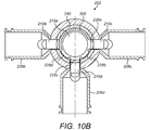
- a valve 202 is illustrated in Figures 10A and 10B , where a fluid inlet 210a and three fluid outlets 210b, 210c, 210d are provided.
- Four valve body openings 228a, 228b, 228c and 228d are provided in the valve body 208 for selectively for selectively placing inlet 210a into fluid communication with outlets 210b, 210s, 210d.
- inlet 210a is in fluid communication with fluid outlets 210c, 210d via the valve body openings 228a, 228c. If the valve body 108 is rotated 45 degrees clockwise, inlet 210a is connected with fluid outlets 210b, 201d via the valve body openings 228b, 228d.
- valve body 208 may adopt can be chosen according to the required flow distribution through the valve 202.
- valve body 8 sealing element 40 and valve housing 4.
- the sealing element 40 and valve body 8 may simply be inserted into the valve housing 4 from one end, and that end then closed by a cap or connector as appropriate.
- valve body 8 The biasing of the valve body 8 against the sealing element 40 both locates the valve body 8 and ensures a good seal between the components.
- sealing element 40 may not only assure good sealing within the valve 2, but may also act as a bearing for the valve body 8.
- valve housing 4 and valve body 8 may be metallic, for example stainless steel or aluminium.
- disc springs 60 may be metallic, for example stainless steel.
- the sealing element 40 may be made from a polymeric material, for example PTFE.
Priority Applications (4)
| Application Number | Priority Date | Filing Date | Title |
|---|---|---|---|
| EP18461627.4A EP3657055A1 (fr) | 2018-11-22 | 2018-11-22 | Vanne de liquide |
| CA3055053A CA3055053A1 (fr) | 2018-11-22 | 2019-09-10 | Soupape a liquide |
| JP2019194856A JP2020085241A (ja) | 2018-11-22 | 2019-10-28 | 流体バルブ |
| US16/686,901 US11592115B2 (en) | 2018-11-22 | 2019-11-18 | Fluid valve |
Applications Claiming Priority (1)
| Application Number | Priority Date | Filing Date | Title |
|---|---|---|---|
| EP18461627.4A EP3657055A1 (fr) | 2018-11-22 | 2018-11-22 | Vanne de liquide |
Publications (1)
| Publication Number | Publication Date |
|---|---|
| EP3657055A1 true EP3657055A1 (fr) | 2020-05-27 |
Family
ID=64456918
Family Applications (1)
| Application Number | Title | Priority Date | Filing Date |
|---|---|---|---|
| EP18461627.4A Pending EP3657055A1 (fr) | 2018-11-22 | 2018-11-22 | Vanne de liquide |
Country Status (4)
| Country | Link |
|---|---|
| US (1) | US11592115B2 (fr) |
| EP (1) | EP3657055A1 (fr) |
| JP (1) | JP2020085241A (fr) |
| CA (1) | CA3055053A1 (fr) |
Cited By (2)
| Publication number | Priority date | Publication date | Assignee | Title |
|---|---|---|---|---|
| DE102020133047A1 (de) | 2020-12-10 | 2022-06-15 | Röchling Automotive Se & Co.Kg | Spritzgegossene Kunststoff-Ventilbaugruppe für ein Kraftfahrzeug |
| DE102021130162A1 (de) | 2021-11-18 | 2023-05-25 | Röchling Automotive SE & Co. KG | Ventilbaugruppe, insbesondere für Kraftfahrzeuge, mit rotierbarem Ventilkörper mit verbesserter Dichtigkeit |
Families Citing this family (5)
| Publication number | Priority date | Publication date | Assignee | Title |
|---|---|---|---|---|
| US11913560B2 (en) * | 2019-10-03 | 2024-02-27 | Process Innovation—Food Safety, Llc | Full-flow sanitary valve |
| WO2021067759A1 (fr) * | 2019-10-03 | 2021-04-08 | Flowtrend, Inc. | Valve sanitaire à écoulement complet |
| DE102020201190A1 (de) * | 2019-10-14 | 2021-04-15 | Vitesco Technologies GmbH | Fluidventil |
| CN112628425B (zh) * | 2020-12-21 | 2022-04-22 | 合肥通用机械研究院有限公司 | 一种低扭矩全行程调节的三通旋塞调节阀 |
| CN113883303A (zh) * | 2021-09-14 | 2022-01-04 | 山东杰控电气技术有限公司 | 一种新型三通分流阀的锥面密封结构 |
Citations (3)
| Publication number | Priority date | Publication date | Assignee | Title |
|---|---|---|---|---|
| DE801827C (de) * | 1949-02-06 | 1951-01-25 | Gustav Friedrich Gerdts | Tankwagen-Umschalthahn |
| FR1047328A (fr) * | 1951-12-28 | 1953-12-14 | Realisations Tech Routieres Re | Perfectionnements aux dispositifs de commande de circulation des fluides |
| US4410003A (en) * | 1980-01-08 | 1983-10-18 | Xomox Corporation | Rotary plug valve |
Family Cites Families (48)
| Publication number | Priority date | Publication date | Assignee | Title |
|---|---|---|---|---|
| US616827A (en) * | 1898-12-27 | John robert deisher | ||
| US1061825A (en) * | 1912-02-21 | 1913-05-13 | William F Dewey | Heater. |
| US1327252A (en) * | 1918-03-26 | 1920-01-06 | Andrew J Paulson | Controlling-valve for multiple fuel-supply pipes |
| US1491115A (en) * | 1922-05-06 | 1924-04-22 | Taylor Huston | Ejector valve |
| US1597523A (en) * | 1923-05-01 | 1926-08-24 | Grund | Multiple intake valve |
| US1561127A (en) * | 1925-04-06 | 1925-11-10 | J B Wise Inc | Water-mixing valve |
| US2001320A (en) * | 1930-12-10 | 1935-05-14 | James E Williamson | Control apparatus |
| US1958228A (en) * | 1931-05-01 | 1934-05-08 | Sinclair Refining Co | Art of coking hydrocarbons |
| US2198386A (en) * | 1937-01-07 | 1940-04-23 | United Aircraft Prod | Valve |
| US2160741A (en) * | 1937-02-05 | 1939-05-30 | Quaker City Iron Works | Distributor control valve for tank vehicles |
| US2127679A (en) * | 1937-04-28 | 1938-08-23 | Dudley Edward Clifford | Hydraulic control valve |
| US2332882A (en) * | 1942-02-05 | 1943-10-26 | Gen Electric | Heat exchanger system |
| US2498846A (en) * | 1945-09-07 | 1950-02-28 | Briggs Mfg Co | Rotary valve internal-combustion engine |
| US2621886A (en) * | 1949-01-27 | 1952-12-16 | Mueller Co | Diverter valve with o ring seal |
| US2630325A (en) * | 1950-12-26 | 1953-03-03 | Earl C Reynolds | Water softener control means |
| US2893429A (en) * | 1956-05-24 | 1959-07-07 | Schaffer Arthur | Mixer valve |
| US3108779A (en) * | 1959-11-12 | 1963-10-29 | Acf Ind Inc | Valve having a valve seat of very thin material |
| US2973181A (en) * | 1960-10-31 | 1961-02-28 | Johnson Jesse Ray | Valve |
| US3383088A (en) * | 1966-02-03 | 1968-05-14 | Duriron Co | Plug valves |
| US3498317A (en) * | 1968-03-22 | 1970-03-03 | Duriron Co | Plug valves having relieved high pressure seal areas |
| US3506239A (en) * | 1968-04-24 | 1970-04-14 | Avm Corp | Valve with sectional body structure and sealing means therefor |
| US3704003A (en) * | 1970-10-30 | 1972-11-28 | Avm Corp | Valve assembly with integral inlet tube and saddle |
| US3700003A (en) * | 1971-04-15 | 1972-10-24 | Russell G Smith | Valve with flow regulating means |
| US3721265A (en) * | 1971-04-29 | 1973-03-20 | Fmc Corp | Three-way valve |
| US3771765A (en) * | 1971-08-31 | 1973-11-13 | Imp Eastman Corp | Self-lapping seal structure |
| US3974869A (en) * | 1972-04-13 | 1976-08-17 | Michio Abe | Fluid flow control valve |
| US3906997A (en) * | 1972-08-24 | 1975-09-23 | Paul J Scaglione | Fluid flow control valve |
| US3834372A (en) | 1973-01-12 | 1974-09-10 | S Turney | Disposable manifold with atmospheric vent |
| US4605036A (en) * | 1977-06-22 | 1986-08-12 | Xomox Corporation | Valve housing with removable self-contained valving unit |
| US4281619A (en) * | 1980-03-10 | 1981-08-04 | Kimberly-Clark Corporation | Method for applying viscous fluid to stock and rotary valve for use in same |
| US4522233A (en) * | 1982-09-29 | 1985-06-11 | Smith & Loveless, Inc. | Multi-position plug valve |
| US4510966A (en) * | 1983-03-28 | 1985-04-16 | Garlock, Inc. | Plug valve with floating stem seal |
| US4535803A (en) * | 1984-03-19 | 1985-08-20 | The Dow Chemical Company | Plug valve |
| US4610266A (en) * | 1985-06-07 | 1986-09-09 | Xomox Corporation | Valve assembly for securing a cover to a valve body with fasteners which are free of tensile stress |
| US5251663A (en) * | 1992-08-14 | 1993-10-12 | The United States Of America As Represented By The Administrator Of The National Aeronautics And Space Administration | High-temperature, high-pressure oxygen metering valve |
| US5590681A (en) * | 1993-07-02 | 1997-01-07 | Frank W. Schaefer, Inc. | Valve assembly |
| US5402983A (en) * | 1993-08-30 | 1995-04-04 | Xomox Corporation | Combined metal and plastic diaphragm assembly for a valve |
| US5950664A (en) * | 1997-02-18 | 1999-09-14 | Amot Controls Corp | Valve with improved combination bearing support and seal |
| US5839399A (en) * | 1997-10-20 | 1998-11-24 | Luce; Norris R. | Cartridge-type rotary valve |
| US6192935B1 (en) * | 1999-11-19 | 2001-02-27 | Lancer Partnership, Ltd. | Dispensing valve mounting assembly |
| US6539899B1 (en) | 2002-02-11 | 2003-04-01 | Visteon Global Technologies, Inc. | Rotary valve for single-point coolant diversion in engine cooling system |
| US7089960B2 (en) | 2003-06-13 | 2006-08-15 | Tlv Co. Ltd. | Ball valve |
| US7789106B2 (en) * | 2003-09-23 | 2010-09-07 | Webstone Company, Inc. | Hot water fluid isolation valve |
| DE102005048166B4 (de) | 2005-10-06 | 2008-01-24 | Zeppelin Silos & Systems Gmbh | Rohrweiche mit verbessertem Übergang und Abgang |
| US9097354B2 (en) * | 2010-06-14 | 2015-08-04 | Thomas Middleton Semmes | Combined changeover and control valve |
| US9631731B2 (en) * | 2012-03-23 | 2017-04-25 | Victaulic Company | Diverter valve |
| JP2015148288A (ja) * | 2014-02-07 | 2015-08-20 | カルソニックカンセイ株式会社 | 弁装置 |
| JP6351352B2 (ja) * | 2014-04-30 | 2018-07-04 | 株式会社不二工機 | 流路切換弁 |
-
2018
- 2018-11-22 EP EP18461627.4A patent/EP3657055A1/fr active Pending
-
2019
- 2019-09-10 CA CA3055053A patent/CA3055053A1/fr active Pending
- 2019-10-28 JP JP2019194856A patent/JP2020085241A/ja active Pending
- 2019-11-18 US US16/686,901 patent/US11592115B2/en active Active
Patent Citations (3)
| Publication number | Priority date | Publication date | Assignee | Title |
|---|---|---|---|---|
| DE801827C (de) * | 1949-02-06 | 1951-01-25 | Gustav Friedrich Gerdts | Tankwagen-Umschalthahn |
| FR1047328A (fr) * | 1951-12-28 | 1953-12-14 | Realisations Tech Routieres Re | Perfectionnements aux dispositifs de commande de circulation des fluides |
| US4410003A (en) * | 1980-01-08 | 1983-10-18 | Xomox Corporation | Rotary plug valve |
Cited By (2)
| Publication number | Priority date | Publication date | Assignee | Title |
|---|---|---|---|---|
| DE102020133047A1 (de) | 2020-12-10 | 2022-06-15 | Röchling Automotive Se & Co.Kg | Spritzgegossene Kunststoff-Ventilbaugruppe für ein Kraftfahrzeug |
| DE102021130162A1 (de) | 2021-11-18 | 2023-05-25 | Röchling Automotive SE & Co. KG | Ventilbaugruppe, insbesondere für Kraftfahrzeuge, mit rotierbarem Ventilkörper mit verbesserter Dichtigkeit |
Also Published As
| Publication number | Publication date |
|---|---|
| US20200166145A1 (en) | 2020-05-28 |
| JP2020085241A (ja) | 2020-06-04 |
| US11592115B2 (en) | 2023-02-28 |
| CA3055053A1 (fr) | 2020-05-22 |
Similar Documents
| Publication | Publication Date | Title |
|---|---|---|
| EP3657055A1 (fr) | Vanne de liquide | |
| CA2387226C (fr) | Robinet a tournant dote de segments d'etancheite avec ressorts d'appoint | |
| US6267353B1 (en) | Self draining valve | |
| US6039304A (en) | Ball valve with modified characteristics | |
| EP2299152B1 (fr) | Soupape à bille dotée d'un plateau de pression anti-rotation | |
| US5735307A (en) | Valve interchangeable between angle and straight | |
| EP1803980B1 (fr) | Soupape à piston creux | |
| US20140209828A1 (en) | Flow characterizing device and ball valve with such a flow characterizing device | |
| KR102166939B1 (ko) | 멀티 포트 밸브 | |
| EP3260745A1 (fr) | Vanne de contrôle de flux | |
| KR20080112147A (ko) | 정지 기능을 갖는 롱스트로크 조절기 밸브 | |
| US10386004B2 (en) | Flow control valve | |
| US5947157A (en) | Throttling device and element | |
| US10393274B2 (en) | Valve for control of a fluid flow | |
| EP3039325B1 (fr) | Vanne papillon actionnée par solénoïde | |
| TWI794323B (zh) | 陶瓷盤閥匣 | |
| US9371936B2 (en) | Balanced globe valve assembly | |
| EP3260746B1 (fr) | Vanne de régulation d'écoulement | |
| US20020109118A1 (en) | Web supported hollow sphere valve | |
| WO2020009952A1 (fr) | Robinet à soupape axiale rotatif | |
| EP1269049B1 (fr) | Clapet a bille a coefficient de debit reglable | |
| KR20230108338A (ko) | 유량 제어용 삼방 밸브 및 온도 제어 장치 | |
| CA2390105A1 (fr) | Insert de robinet |
Legal Events
| Date | Code | Title | Description |
|---|---|---|---|
| PUAI | Public reference made under article 153(3) epc to a published international application that has entered the european phase |
Free format text: ORIGINAL CODE: 0009012 |
|
| STAA | Information on the status of an ep patent application or granted ep patent |
Free format text: STATUS: THE APPLICATION HAS BEEN PUBLISHED |
|
| AK | Designated contracting states |
Kind code of ref document: A1 Designated state(s): AL AT BE BG CH CY CZ DE DK EE ES FI FR GB GR HR HU IE IS IT LI LT LU LV MC MK MT NL NO PL PT RO RS SE SI SK SM TR |
|
| AX | Request for extension of the european patent |
Extension state: BA ME |
|
| STAA | Information on the status of an ep patent application or granted ep patent |
Free format text: STATUS: REQUEST FOR EXAMINATION WAS MADE |
|
| 17P | Request for examination filed |
Effective date: 20201127 |
|
| RBV | Designated contracting states (corrected) |
Designated state(s): AL AT BE BG CH CY CZ DE DK EE ES FI FR GB GR HR HU IE IS IT LI LT LU LV MC MK MT NL NO PL PT RO RS SE SI SK SM TR |
|
| STAA | Information on the status of an ep patent application or granted ep patent |
Free format text: STATUS: EXAMINATION IS IN PROGRESS |
|
| 17Q | First examination report despatched |
Effective date: 20220620 |