EP3656600A1 - Zugbetriebsunterstützungsvorrichtung, zugbetriebsunterstützungssystem und zugbetriebsunterstützungsverfahren - Google Patents
Zugbetriebsunterstützungsvorrichtung, zugbetriebsunterstützungssystem und zugbetriebsunterstützungsverfahren Download PDFInfo
- Publication number
- EP3656600A1 EP3656600A1 EP18835604.2A EP18835604A EP3656600A1 EP 3656600 A1 EP3656600 A1 EP 3656600A1 EP 18835604 A EP18835604 A EP 18835604A EP 3656600 A1 EP3656600 A1 EP 3656600A1
- Authority
- EP
- European Patent Office
- Prior art keywords
- train
- information
- driving operation
- speed
- operation determination
- Prior art date
- Legal status (The legal status is an assumption and is not a legal conclusion. Google has not performed a legal analysis and makes no representation as to the accuracy of the status listed.)
- Granted
Links
- 238000000034 method Methods 0.000 title claims description 69
- 238000004422 calculation algorithm Methods 0.000 claims description 11
- 238000004088 simulation Methods 0.000 claims description 11
- 238000001514 detection method Methods 0.000 claims description 5
- 238000010586 diagram Methods 0.000 description 15
- 230000000694 effects Effects 0.000 description 15
- 238000004364 calculation method Methods 0.000 description 12
- 238000004891 communication Methods 0.000 description 11
- 230000001133 acceleration Effects 0.000 description 6
- 230000005540 biological transmission Effects 0.000 description 3
- 239000000284 extract Substances 0.000 description 2
- 239000002699 waste material Substances 0.000 description 2
- 238000010276 construction Methods 0.000 description 1
- 230000001934 delay Effects 0.000 description 1
- 238000009434 installation Methods 0.000 description 1
Images


Classifications
-
- B—PERFORMING OPERATIONS; TRANSPORTING
- B61—RAILWAYS
- B61L—GUIDING RAILWAY TRAFFIC; ENSURING THE SAFETY OF RAILWAY TRAFFIC
- B61L15/00—Indicators provided on the vehicle or train for signalling purposes
- B61L15/0058—On-board optimisation of vehicle or vehicle train operation
-
- B—PERFORMING OPERATIONS; TRANSPORTING
- B60—VEHICLES IN GENERAL
- B60L—PROPULSION OF ELECTRICALLY-PROPELLED VEHICLES; SUPPLYING ELECTRIC POWER FOR AUXILIARY EQUIPMENT OF ELECTRICALLY-PROPELLED VEHICLES; ELECTRODYNAMIC BRAKE SYSTEMS FOR VEHICLES IN GENERAL; MAGNETIC SUSPENSION OR LEVITATION FOR VEHICLES; MONITORING OPERATING VARIABLES OF ELECTRICALLY-PROPELLED VEHICLES; ELECTRIC SAFETY DEVICES FOR ELECTRICALLY-PROPELLED VEHICLES
- B60L15/00—Methods, circuits, or devices for controlling the traction-motor speed of electrically-propelled vehicles
- B60L15/20—Methods, circuits, or devices for controlling the traction-motor speed of electrically-propelled vehicles for control of the vehicle or its driving motor to achieve a desired performance, e.g. speed, torque, programmed variation of speed
- B60L15/2009—Methods, circuits, or devices for controlling the traction-motor speed of electrically-propelled vehicles for control of the vehicle or its driving motor to achieve a desired performance, e.g. speed, torque, programmed variation of speed for braking
-
- B—PERFORMING OPERATIONS; TRANSPORTING
- B61—RAILWAYS
- B61L—GUIDING RAILWAY TRAFFIC; ENSURING THE SAFETY OF RAILWAY TRAFFIC
- B61L15/00—Indicators provided on the vehicle or train for signalling purposes
- B61L15/0062—On-board target speed calculation or supervision
-
- B—PERFORMING OPERATIONS; TRANSPORTING
- B61—RAILWAYS
- B61L—GUIDING RAILWAY TRAFFIC; ENSURING THE SAFETY OF RAILWAY TRAFFIC
- B61L27/00—Central railway traffic control systems; Trackside control; Communication systems specially adapted therefor
- B61L27/10—Operations, e.g. scheduling or time tables
- B61L27/14—Following schedules
-
- B—PERFORMING OPERATIONS; TRANSPORTING
- B61—RAILWAYS
- B61L—GUIDING RAILWAY TRAFFIC; ENSURING THE SAFETY OF RAILWAY TRAFFIC
- B61L15/00—Indicators provided on the vehicle or train for signalling purposes
- B61L15/0072—On-board train data handling
-
- B—PERFORMING OPERATIONS; TRANSPORTING
- B61—RAILWAYS
- B61L—GUIDING RAILWAY TRAFFIC; ENSURING THE SAFETY OF RAILWAY TRAFFIC
- B61L27/00—Central railway traffic control systems; Trackside control; Communication systems specially adapted therefor
- B61L27/60—Testing or simulation
-
- Y—GENERAL TAGGING OF NEW TECHNOLOGICAL DEVELOPMENTS; GENERAL TAGGING OF CROSS-SECTIONAL TECHNOLOGIES SPANNING OVER SEVERAL SECTIONS OF THE IPC; TECHNICAL SUBJECTS COVERED BY FORMER USPC CROSS-REFERENCE ART COLLECTIONS [XRACs] AND DIGESTS
- Y02—TECHNOLOGIES OR APPLICATIONS FOR MITIGATION OR ADAPTATION AGAINST CLIMATE CHANGE
- Y02T—CLIMATE CHANGE MITIGATION TECHNOLOGIES RELATED TO TRANSPORTATION
- Y02T10/00—Road transport of goods or passengers
- Y02T10/60—Other road transportation technologies with climate change mitigation effect
- Y02T10/72—Electric energy management in electromobility
-
- Y—GENERAL TAGGING OF NEW TECHNOLOGICAL DEVELOPMENTS; GENERAL TAGGING OF CROSS-SECTIONAL TECHNOLOGIES SPANNING OVER SEVERAL SECTIONS OF THE IPC; TECHNICAL SUBJECTS COVERED BY FORMER USPC CROSS-REFERENCE ART COLLECTIONS [XRACs] AND DIGESTS
- Y02—TECHNOLOGIES OR APPLICATIONS FOR MITIGATION OR ADAPTATION AGAINST CLIMATE CHANGE
- Y02T—CLIMATE CHANGE MITIGATION TECHNOLOGIES RELATED TO TRANSPORTATION
- Y02T90/00—Enabling technologies or technologies with a potential or indirect contribution to GHG emissions mitigation
- Y02T90/10—Technologies relating to charging of electric vehicles
- Y02T90/16—Information or communication technologies improving the operation of electric vehicles
Definitions
- the present invention relates to a train operation support device, a train operation support system, and a train operation support method, and is preferably applied to a train operation support device, a train operation support system, and a train operation support method for determining an appropriate driving operation of a train.
- a train operation control system of PTL 1 aims to make it possible to avoid a difference in train position and speed with respect to a re-created speed profile.
- a ground device includes a speed profile generation unit that generates a speed profile from the time after the set time has elapsed using the information on the predicted train position and speed after the set time has elapsed.
- Train traveling in the railway system is affected by fluctuation factors such as an overhead wire voltage and a boarding rate that fluctuate for each traveling, and the acceleration and deceleration change. For this reason, it is not possible to cause a different train to travel with a speed profile of exactly the same position and speed as the speed profile of a certain train, and even if the switching timing of the driving operations is calculated in advance, it has been difficult to reproduce that operation. In other words, it is necessary to determine an appropriate driving operation in real time in order to realize traveling that realizes system goals such as ensuring punctuality and improving energy saving effect while dealing with such fluctuation factors.
- the computing cost on the equipment on the vehicle can be reduced by performing traveling computation on the ground calculation device without performing the computation on the equipment on the vehicle.
- the train operation control system of PTL 1 when a driving operation corresponding to a plurality of conditions is transmitted in order to cope with the influence of fluctuation factors, since the speed profile for each of the many conditions needs to be always transmitted from the ground calculation device, the load on the communication capacities increases. As a result, under the equipment with limited communication capacities, a sufficient communication state cannot be maintained, and there is a possibility that an appropriate driving operation cannot be determined.
- the present invention has been made in consideration of the above points and aims to propose a train operation support device, a train operation support system, and a train operation support method which can support determination of a driving operation with which ensuring of punctuality and energy saving effect can be expected in a train system having limited computing powers and communication capacities.
- a train operation support device which provides, for a train system that determines a driving operation of a train based on predetermined input information, driving operation determination table data information that constitutes one of the predetermined input information and provides a determination criterion for the driving operation, the train operation support device, including: an overall table creation unit that creates overall table information according to table information relating to an entire target section on which the train travels; and a table region limiting unit that limits, from the overall table information, table information of a region where switching of the driving operation is performed within a fluctuation range of an external factor that affects traveling of the train, and outputs the limited table information as the driving operation determination table data information.
- a train operation support system for supporting a driving operation of a train
- the train operation support system including: a train position detector that outputs train position information indicating a position of the train; a train speed detector that outputs train speed information indicating a speed of the train; a driving operation determination table data creation unit that creates and outputs driving operation determination table data information providing a determination criterion for the driving operation for each position of the train and each speed of the train based on external factor range information that defines a fluctuation range of an external factor that affects traveling of the train; and a driving operation determination unit that determines a driving operation based on the train position information, the train speed information, and the driving operation determination table data information.
- the driving operation determination table data creation unit includes an overall table creation unit that creates overall table information according to table information relating to an entire target section on which the train travels, and a table region limiting unit that limits, from the overall table information, table information of a region where switching of the driving operation is performed within a fluctuation range of the external factor, and outputs the limited table information as the driving operation determination table data information.
- a train operation support method by a train operation support system that supports a driving operation of a train, the train operation support method including: a train position detection step for outputting train position information indicating a position of the train; a train speed detection step for outputting train speed information indicating a speed of the train; a driving operation determination table data creation step for creating and outputting driving operation determination table data information providing a determination criterion for the driving operation for each position of the train and each speed of the train based on external factor range information that defines a fluctuation range of an external factor that affects traveling of the train; and a driving operation determination step for determining a driving operation based on the train position information, the train speed information, and the driving operation determination table data information.
- the driving operation determination table data creation step includes an overall table creation step for creating overall table information according to table information relating to an entire target section on which the train travels, and a table region limiting step for limiting, from the overall table information, table information of a region where switching of the driving operation is performed within a fluctuation range of the external factor, and outputting the limited table information as the driving operation determination table data information.
- FIG. 1 is a functional configuration diagram of the train operation support system according to the embodiment of the present invention.
- a train operation support system 1 is a system that controls the operation of a train 10, and is realized by, for example, an onboard device mounted on the train 10. As illustrated in FIG. 1 , the train operation support system 1 includes a driving operation determination table data creation unit 11, a train position detector 12, a train speed detector 13, a driving operation determination unit 14, and a propulsion 15, and a display unit 16.
- the driving operation determination table data creation unit 11 has a function of calculating driving operation determination table data information, which is information necessary for determining driving operation (providing a determination criterion for driving operation), and braking pattern information, and outputs the driving operation determination table data information and the braking pattern information obtained by calculation to the driving operation determination unit 14.
- the driving operation determination table data creation unit 11 corresponds to a train operation support device of the present invention, and can be realized by, for example, a computer of an onboard device mounted on the train 10.
- the driving operation determination table data creation unit 11 can also be realized by a calculation device installed outside the train 10, for example, on the ground. In this case, the driving operation determination table data information and the braking pattern information calculated by the driving operation determination table data creation unit 11 are transmitted to the train 10.
- the train position detector 12 has a function of detecting the position of the train 10, and outputs the detected train position to the driving operation determination unit 14.
- the train position detector 12 is, for example, a train position detection device using a track circuit, other general positioning devices, or the like.
- the train speed detector 13 has a function of detecting the speed of the train 10, and outputs the detected train speed to the driving operation determination unit 14.
- the train speed detector 13 is, for example, a tachometer generator.
- the driving operation determination unit 14 has a function of determining driving operation information including information related to a driving operation to be performed on the train 10 based on information input from each unit (driving operation determination table data information, braking pattern information, train position information, and train speed information) .
- the driving operation determination unit 14 outputs the determined driving operation information to the propulsion 15 and the display unit 16.
- the driving operation determination unit 14 can be realized by, for example, a computer of an onboard device mounted on the train 10.
- the propulsion 15 has a function of performing drive control of a motor, an engine, etc., and realizes train traveling that the train operation support system 1 intends by performing drive control based on the driving operation information output from the driving operation determination unit 14.
- the propulsion 15 is a drive control panel of the train 10, for example.
- the display unit 16 has a display function and displays information related to train traveling determined by the train operation support system 1 based on the driving operation information output from the driving operation determination unit 14.
- the display unit 16 is realized by, for example, a general display or a display panel, and may be a display of the cab of the train 10 or a terminal held by a driver.
- the driving operation determination unit 14 determines driving operation information regarding the driving operation to be supported, and the speed profile when the driving operation of the train 10 is performed based on the driving operation information is called a speed profile according to the present embodiment.
- the speed profile represents the speed at each position where the train travels, in other words, the relationship between the position and speed in the traveling section of the train.
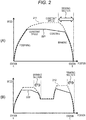
- FIG. 2 is a diagram for describing an image of a speed profile by the train operation support system according to the present embodiment.
- FIG. 2(A) illustrates a speed profile in a traveling section from station A to station B
- FIG. 2 (B) illustrates a speed profile in a traveling section from station B to station C.
- the middle of the traveling section in FIG. 2(B) there is a slowdown section where the speed limit is set lower than those of the surrounding sections.
- FIGS. 2 (A) and 2(B) examples of speed profiles of the train 10 by the train operation support system 1 according to the present embodiment are represented by solid lines 221 and 222, respectively. Further, in FIGS. 2(A) and 2(B) , for comparison, as an example of a conventional speed profile, a speed profile by "fastest traveling" is represented by broken lines 211 and 212, respectively.
- “Fastest traveling” means that the train 10 travels fastest while complying with the speed limit (within the speed limit tolerance) .
- the train 10 accelerates without exceeding the upper limit of speed limit (powering operation), and in the section where it cannot accelerate further (exceeds the upper limit of speed limit), performs a constant speed operation to maintain the train speed, and when approaching station B at the stop point, performs a deceleration operation using a brake.
- the train 10 can arrive at the stop point in the shortest time while complying with the speed limit.
- a slowdown section as shown in FIG.
- the driving operation for performing such a speed profile by the fastest traveling can be determined based on constraints such as vehicle performance and route environment.
- constraints such as vehicle performance and route environment.
- a train operation schedule is planned to allow some margin time. When the driving operation is performed with the speed profile based on the fastest traveling, the train arrives earlier than the planned time, and thus there is a problem also in terms of ensuring punctuality.
- FIGS. 2(A) and 2(B) exemplify a section where the brake is used (braking section) in the speed profile of the fastest traveling, but in this description, the speed profile in the braking section is defined as a braking pattern.
- the braking pattern can be used to determine whether or not it is necessary to operate the brake while driving. Specifically, when the speed at a certain position is equal to or higher than that of the braking pattern at the position, it can be determined that the braking operation is necessary.
- the train operation support system 1 can calculate the driving operation of the train 10 with which energy saving effect can be expected while ensuring punctuality.
- the characteristics of the speed profile (solid lines 221 and 222) by such driving operation will be described.
- the speed profile according to the present embodiment when compared to the speed profile by the fastest traveling, has two differences: execution of the coasting operation and switching to the constant speed operation at a speed less than the speed limit or the coasting operation.
- solid line 221 is similar to broken line 211 of the fastest traveling in that the powering operation is performed after leaving station A, but before the upper limit of the speed limit is reached, it has been switched to the constant speed operation.
- the point that the coasting operation is performed before entering the braking section after the constant speed operation is also different from broken line 211, and the deceleration operation using the brake is performed after the coasting operation.
- the coasting operation means an operation by coasting traveling that causes the train 10 to travel by inertia without performing acceleration by the drive device or deceleration by the brake, and the train 10 travels by the kinetic energy that the train 10 has had so far.
- the train in comparison with the conventional fastest traveling, the train can be made to arrive at the stop point by the planned time (ensuring punctuality) by partially performing powering operation and deceleration operation (braking) similar to the speed profile by the fastest traveling, while the large energy saving effect can be expected by suppressing acceleration to the maximum speed and incorporating coasting operation.
- the train 10 when the train 10 is decelerated, not only deceleration operation by the brake is performed but also constant speed operation and coasting operation are incorporated, and thereby sudden deceleration is avoided. Therefore, it can also be expected to reduce the discomfort and pressure caused by the sudden deceleration and to improve passenger's comfort.
- the driving operation determination unit 14 determines the switching timing of the respective driving operations using the driving operation determination table data information. Therefore, in the next chapter, a process by the driving operation determination unit 14 (driving operation determination process) will be described in detail.
- the driving operation determination table data information is used for the driving operation determination process by the driving operation determination unit 14.
- the driving operation determination table data information includes table information related to the constant speed operation (constant speed table information) and table information related to the coasting operation (coasting table information). Both table information is data that can be handled in the same table format.
- the driving operation determination table data information (constant speed table information, coasting table information) will be described with reference to FIGS. 3 and 4 .
- FIG. 3 is a diagram (part 1) for describing an example of the driving operation determination table data information.
- a table 230 shown in FIG. 3 is an image example of table information (constant speed table information or coasting table information) included in the driving operation determination table data information.
- the table 230 is represented by two-dimensional data based on a speed 231 and a position 232 of the train.
- the speed of the train 10 in the vertical axis (speed 231), the speed of the train 10 is divided by 10km/h up to the maximum speed, and in the horizontal axis (position 232), the departure point to the arrival point is divided at 100 m intervals, and thereby two-dimensional data having grid points are generated.
- "x" is used for simplicity, but a table value corresponding to the speed 231 and the position 232 is written at each grid point.
- the information of the entire range (region P) can be handled as table information, but when the conditions can be limited in advance, the information of the predetermined range (region Q) may be handled as table information.
- the table values of the low speed near the stop and the high speed near the upper limit of the speed limit are assumed not to be usually referred to, and thus they can be excluded in advance as unnecessary in the constant speed table information as the target to be processed by the driving operation determination unit 14.
- the table values immediately after departure (powering operation is performed) and immediately before arrival (deceleration operation is performed) are assumed not to be referred to, and thus they can be excluded in advance as unnecessary in the constant speed table information. In this way, by preliminarily limiting the data to be processed, it is possible to reduce the processing load by the driving operation determination unit 14 and to expect the effect of suppressing the waste of computing powers.
- the driving operation determination table data information (constant speed table information, coasting table information) limited to a range (for example, region Q) in which a driving operation may actually be performed by the driving operation determination table data creation unit 11 is created and output to the driving operation determination unit 14, the processing load by the driving operation determination unit 14 can be reduced, and the waste of computing powers can be suppressed.
- FIG. 4 is a diagram (part 2) for describing an example of the driving operation determination table data information.
- the table information of the driving operation determination table data information may have a data configuration in which combinations of elements (position 241, speed 242, table value 243) are listed.
- the individual table values are set so as to include information which can be utilized for determination of the switching timing of the driving operations by the driving operation determination unit 14.
- the driving operation determination unit 14 can obtain a desirable determination result in order to achieve the system goals such as punctuality and energy saving by determining the timing of switching the driving operation to the constant speed operation as follows. That is, when T is 72 seconds or more, it is determined to switch the current driving operation to constant speed operation. When T is less than 72 seconds, it is preferable to determine to maintain the original driving operation as is without switching the driving operations.
- the constant speed table information and the coasting table information are set, for example, for each inter station, and the constant speed table value for the current state is defined by reading information corresponding to the current state consisting of the train position and the train speed from the constant speed table information.
- the constant speed table value may be defined based on internal divisions in the position and speed directions from the four intersections of the position and speed surrounding the current state.
- FIG. 5 is a flowchart illustrating a processing procedure example of the driving operation determination process.
- the driving operation determination process is a process in which the driving operation determination unit 14 determines the driving operation based on the braking pattern information and driving operation determination table data information output from the driving operation determination table data creation unit 11, and the train position output from the train position detector 12 and the train speed output from the train speed detector 13.
- the algorithm illustrated in FIG. 5 determines the driving operation by selecting one appropriate driving operation from among the driving operations of "fastest operation (powering operation similar to the fastest traveling)", “constant speed (constant speed operation)”, “coasting (coasting operation)”, and “braking (deceleration operation using a brake)”.
- each process of FIG. 5 will be described.
- step S101 the driving operation is set to the preceding driving operation.
- step S102 the relationship between the current train position and the end point of the current braking pattern is determined.
- the current train position can be specified by the train position output from the train position detector 12, and the end point of the braking pattern means the point closest to the arrival point in the braking pattern.
- the driving operation determination unit 14 determines whether or not the current train position has exceeded the end point of the braking pattern.
- the process proceeds to step S103.
- the process proceeds to step S105.
- step S103 since the current train position exceeds the end point of the braking pattern, the train 10 may be accelerated within the speed limit range, and thus the driving operation determination unit 14 sets the driving operation to "fastest operation” and proceeds to step S104.
- step S104 the driving operation determination unit 14 resets the current braking pattern.
- a braking pattern after resetting a braking pattern that is closest to the arrival point side with respect to the current train position is selected. Thereafter, the process proceeds to step S105.
- step S105 whether or not the current train position and train speed exist below the braking pattern is determined by determining the following two determination items for the relationship between the current train position and train speed and the braking pattern. Specifically, the first determination item is whether or not a braking pattern is defined at the current train position, and the second determination item is whether or not the current train speed is less than the speed limit set in the braking pattern at the current train position.
- the determination result of the first or second determination item is true (YES in step S105)
- the process proceeds to step S107, and the determination results of both the first and second determination items are false (NO in step S105), the process proceeds to step S106.
- step S106 since the braking pattern is defined for the current train position in the determination of step S105, and the current train speed is determined to be equal to or higher than the speed limit of the braking pattern, it is determined that a deceleration operation using a brake is necessary to reduce the speed of the train 10 quickly. Thus, in step S106, the driving operation is set to "braking", and the process proceeds to step S107.
- step S107 it is determined whether or not the driving operation is set to something other than "braking".
- the driving operation is set to something other than "braking” (YES in step S107)
- the process proceeds to step S108.
- the driving operation is set to "braking” (NO in step S107)
- the process proceeds to step S113, the currently set driving operation (in this case, "braking") is output as driving operation information, and the driving operation determination process is terminated.
- step S108 a table value corresponding to the current train position and train speed is read from the constant speed table information (see FIGS. 3 and 4 ) included in the driving operation determination table data information, and set as a constant speed table value T1.
- T1 is equal to -1.
- step S108 also for the coasting table information included in the driving operation determination table data information, a table value corresponding to the current train position and train speed is read and set as a coasting table value T2.
- T2 is equal to -1.
- a remaining time T until the target arrival time is calculated based on the current time and the target arrival time.
- step S109 it is determined whether or not the coasting operation can be selected as the driving operation. Specifically, in step S109, the remaining time T and the coasting table value T2 obtained in step S108 are used to determine the true/false of the determination formula "T2 is negative or T ⁇ T2". When the determination result is true (YES in step S109), it means that the coasting operation cannot be selected, and the process proceeds to step S111. When the determination result is false (NO in step S109), it means that the coasting operation can be selected, and the process proceeds to step S110.
- step S110 since in the determination in step S109, it is determined that the coasting table value T2 is not negative (that is, the coasting table value corresponding to the current train position and train speed is defined in the coasting table information), and the remaining time T is equal to or greater than the coasting table value T2 (that is, there is a remaining time during which the coasting operation can be performed), it is determined that the coasting operation can be selected. Therefore, in step S110, the driving operation determination unit 14 sets the driving operation to "coasting". After step S110, the process proceeds to step S113, where the currently set driving operation (in this case, "coasting") is output as driving operation information, and the driving operation determination process is terminated.
- the currently set driving operation in this case, "coasting”
- step S111 since it is determined by the determination in step S109 that the driving operation of the coasting operation cannot be selected, it is determined whether or not the constant speed operation can be selected as the driving operation. Specifically, in step S111, the remaining time T and the constant speed table value T1 obtained in step S108 are used to determine the true/false of the determination formula "T1 is negative or T ⁇ T1".
- the determination result is true (YES in step S111)
- the process proceeds to step S113, where the currently set driving operation (in this case, "fastest operation”) is output as driving operation information, and the driving operation determination process is terminated.
- the determination result in step S109 is false (NO in step S111)
- step S112 since in the determination in step S111, it is determined that the constant speed table value T1 is not negative (that is, the constant speed table value corresponding to the current train position and train speed is defined in the constant speed table information), and the remaining time T is equal to or greater than the constant speed table value T1 (that is, there is a remaining time in which constant speed operation can be performed), it is determined that the constant speed operation can be selected.
- the driving operation determination unit 14 sets the driving operation to "constant speed”.
- step S113 the currently set driving operation (in this case, "constant speed”) is output as driving operation information, and the driving operation determination process is terminated.
- the driving operation determination unit 14 determines whether or not to switch to each driving operation based on various pieces of input information and can determine an appropriate driving operation to be executed.
- a table region limiting unit 118 (see FIG. 6 ) of the driving operation determination table data creation unit 11 described later has a function of executing a simulation using an algorithm similar to that of the driving operation determination process by the driving operation determination unit 14. That is, the table region limiting unit 118 of the driving operation determination table data creation unit 11 can simulate an appropriate speed profile of the present invention including constant speed operation and coasting operation as illustrated by solid lines 221 and 222 in FIG. 2 by virtually calculating the driving operation by the process similar to the driving operation determination process illustrated in FIG. 5 . Detailed processing by the table region limiting unit 118 will be described in detail with reference to FIG. 8 .
- FIG. 6 is a diagram showing a configuration example of the driving operation determination table data creation unit.
- the driving operation determination table data creation unit 11 is a train operation support device that creates braking pattern information and driving operation determination table data information necessary for determining the driving operation in the driving operation determination unit 14.
- the driving operation determination table data creation unit 11 includes an overall table creation unit 115 and the table region limiting unit 118.
- the overall table creation unit 115 calculates overall table information 116 and braking pattern information 117 for the entire target section using speed limit information 111, train condition information 112, terrain condition information 113, and external factor range information 114 as input information.
- the table region limiting unit 118 creates driving operation determination table data information 119 using the speed limit information 111, the train condition information 112, the terrain condition information 113, the external factor range information 114, and the overall table information 116 as input information.
- the speed limit information 111, the train condition information 112, the terrain condition information 113, and the external factor range information 114, which are input information in the driving operation determination table data creation unit 11 configured as described above, will be described.
- the speed limit information 111 is information determined regarding the speed limit of the train 10 and includes information on the start position, end position, and speed limit of each speed limit section.
- the information on speed limit included in the speed limit information 111 may include speed limit information always effective due to curves, gradients, track layout, and the like, and speed limit information temporarily effective due to the effects of weather, construction near the route, and the like.
- the train condition information 112 is information necessary to reproduce the physical behavior of the train 10, and specifically includes, for example, information such as the total weight, train length, tensile force, braking force, efficiency during powering, and efficiency during braking in the train 10.
- the terrain condition information 113 is information on a route and a diagram necessary for generating a speed profile, and specifically, for example, includes the position information of the departure point, the position information of the arrival point, the gradient information between the departure point and the arrival point, the curve information between the starting point and the arrival point, and information on a predetermined traveling time to be satisfied between the starting point and the arrival point.
- the external factor range information 114 is information representing a range or a representative value of an external factor value that may change every time the train 10 travels among physical quantities that affect the operation of the train 10.
- Specific physical quantities that can be included in the external factor range information 114 include, for example, boarding rate information, overhead wire voltage fluctuation range information, wind direction/wind speed information that affects the running resistance of the train 10, or transmission delay and control delay range information.
- the external factor range information 114 includes information on all or a part of the ranges of the respective physical quantities.
- Each piece of information included in the external factor range information 114 only needs to be given a condition such that the fluctuation range is determined for each train (including different traveling opportunities by the same train 10), and various giving modes can be assumed.
- the external factor range information 114 may provide information on the entire range that each physical quantity can take, such as "the boarding rate is 0% to 250%".
- the external factor range information 114 may provide range information corresponding to each condition related to traveling of the train 10.
- the holding mode of the range information related to each physical quantity does not need to have a single mode, and the range information related to each physical quantity may be recorded in an independent form for each physical quantity.
- the boarding rate may be recorded as information on the entire possible range
- the overhead wire voltage may be recorded for each train number
- the wind speed may be recorded for each time zone.
- FIG. 7 is a diagram illustrating an example of external factor range information.
- a table 250 shown in FIG. 7 is a specific example of the external factor range information 114 according to the giving mode of the second example.
- No 251 is a number that collectively indicates a combination of one or more conditions written in a condition 252 and corresponds to a "traveling condition" in FIG. 8 described below.
- the condition 252 conditions related to the traveling of the train 10 are written, and specifically traveling time (time zone), traveling section (section), operation type (type), and traveling direction (direction) are exemplified.
- the range information of the external factor value for the train satisfying the condition 252 is written, and specifically, the boarding rate and the overhead wire voltage are exemplified.
- traveling conditions of No 251 are not classified as a group of multiple conditions as in the condition 252 in FIG. 7 , but for example, for each individual train number on the train timetable, the range information of the external factor value may be indicated and classified as "traveling conditions".
- the overall table creation unit 115 uses the input information (speed limit information 111, train condition information 112, terrain condition information 113, and external factor range information 114) to calculate information on the remaining time for switching the driving operation at "each position" between the departure point and the arrival point of the train 10, create table information (constant speed table information, coasting table information) corresponding to the entire target section, and output the table information as the overall table information 116.
- "each position” means a train position where it is determined whether or not to switch the driving operations by the driving operation determination process of the driving operation determination unit 14, and the overall table creation unit 115 calculate the remaining time for switching the driving operations for each train position.
- the overall table creation unit 115 uses the input information to calculate the braking position/speed sequence in the section where braking is required between the departure point and the arrival point of the train 10, and outputs it as the braking pattern information 117.
- the overall table creation unit 115 calculates and outputs information related to the entire target section.
- the overall table information 116 related to the entire target section for example, it is preferable to image the range information of the region P in FIG. 3 .
- the table region limiting unit 118 estimates range information in which a driving operation may actually be performed, and creates and outputs only table information (constant speed table information and coasting table information) within the estimated range as the driving operation determination table data information 119.
- FIG. 8 is a flowchart showing a processing procedure example of the driving operation determination table data creation process.
- the driving operation determination table data creation process illustrated in FIG. 8 is a process for the table region limiting unit 118 to create the driving operation determination table data information 119.
- FIG. 9 is a diagram for describing a simulation image of a speed profile in the driving operation determination table data creation process.
- the driving operation determination table data creation process will be described along the processing procedure illustrated in FIG. 8 with reference to the image illustrated in FIG. 9 as appropriate.
- the table region limiting unit 118 has a function of executing a simulation capable of calculating an appropriate speed profile (for example, solid lines 221 and 222 in FIG. 2 ) of the present invention including the constant speed operation and the coasting operation by the driving operation determination process (see FIG. 5 ) using the algorithm similar to that of the driving operation determination unit 14.
- the table region limiting unit 118 determines an allowable traveling time width before limiting the table information (constant speed table information and coasting table information) to be the driving operation determination table data information 119.
- the train operation time may have a predetermined allowable width for the target traveling time (target traveling time), and this allowable width corresponds to the "traveling time width".
- step S201 specifically, for example, when the traveling time width is represented by Tmin to Tmax, in a case that the target traveling time from the calculation departure point to the arrival target position is T0 seconds and the allowable width is 10 seconds, the minimum traveling time Tmin is set to "T0 - 10" and the maximum traveling time Tmax is set to "T0 + 10". Note that the allowable width is not necessarily the same between large and small.
- the table region limiting unit 118 thus set determines information on the table region utilized in the range of Tmin to Tmax in the subsequent processing.
- the table region limiting unit 118 repeatedly executes the processing of steps S202 to S207 for each of the traveling conditions (for example, No 251 in FIG. 7 ) given from the external factor range information 114 (loop processing).
- a powering pattern in a combination of fluctuation conditions is calculated. Since the acceleration is affected by fluctuations in external factors, the powering pattern is different for each combination.
- a process for examining a region where switching to the constant speed operation is performed is performed.
- step S202 the table region limiting unit 118 sets the target traveling time at departure to Tmin and performs a simulation that calculates the appropriate speed profile of the present invention including constant speed operation and coasting operation while calculating the driving operation by the driving operation determination process (see FIG. 5 ) using the algorithm similar to that of the driving operation determination unit 14.
- a speed profile 260 (broken line 260 in the image of FIG. 9 ) is calculated by this simulation.
- step S203 the table region limiting unit 118 extracts, in the speed profile 260 calculated in step S202, a point at which switching from powering operation to constant speed operation is performed (corresponding to a point 261 in the image of FIG. 9 and hereinafter referred to as a powering end point 261) and a point at which switching to coasting operation is performed (corresponding to a point 262 in the image of FIG. 9 and hereinafter referred to as a coasting start point 262).
- step S204 the table region limiting unit 118 sets the target traveling time at departure to Tmax and performs, in the same manner as in step S202, a simulation that calculates an appropriate speed profile of the present invention including constant speed operation and coasting operation while calculating the driving operation by the driving operation determination process (see FIG. 5 ) using the algorithm similar to that of the driving operation determination unit 14.
- a speed profile 270 (broken line 270 in the image of FIG. 9 ) is calculated by this simulation.
- step S205 the table region limiting unit 118 extracts, in the speed profile 270 calculated in step S204, a point at which switching to the constant speed operation is performed (corresponding to a point 271 in the image of FIG. 9 and hereinafter referred to as a powering end point 271) and a point at which switching to the coasting operation is performed (corresponding to a point 272 in the image of FIG. 9 and hereinafter referred to as a coasting start point 272).
- step S206 the table region limiting unit 118 calculates and records a constant speed switching region R using the powering end point 261 extracted in step S203 and the powering end point 271 extracted in step S205.
- the calculation method of the constant speed switching region R will be described with reference to FIG. 9 .
- step S207 the table region limiting unit 118 calculates and records a coasting switching region S using the coasting start point 262 extracted in step S203 and the coasting start point 272 extracted in step S205.
- the calculation method of the coasting switching region S will be described with reference to FIG. 9 .
- the constant speed switching region R and the coasting switching region S under the traveling condition selected in the loop processing are calculated and recorded by the processing in steps S202 to S207 and all the loop processing are performed, and thereby, the constant speed switching region R and the coasting switching region S are calculated and recorded for all combinations of external factors (traveling conditions) given from the external factor range information 114.
- steps S208 and S209 the constant speed table information output region and the coasting table information output region are determined using the constant speed switching region R and the coasting switching region S obtained by the loop processing.
- step S208 the union of the constant speed switching region R calculated for each combination of external factors (traveling conditions) by the above loop processing, which is determined to be a region where there is a possibility of switching to constant speed operation within the fluctuation range of the external factors, is determined as the constant speed table information output region.
- step S209 the union of the coasting switching region S calculated for each combination of external factors (traveling conditions) by the above loop processing, which is determined to be a region where there is a possibility of switching to constant speed operation within the fluctuation range of the external factor, is determined as the coasting table information output region.
- the processing of steps S201 to S208 is performed, so that the output region of the driving operation determination table data information 119 (constant speed table information and coasting table information) can be limited not to the table information related to the entire target section (overall table information 116) but to the range information in which there is a possibility that the driving operation can actually be performed in consideration of the fluctuation range of the external factor.
- the driving operation determination table data information 119 based on the range information to which the output region is limited in this way, for example, it is preferable to image the range information of the region Q in FIG. 3 .
- the driving operation determination table data creation unit 11 outputs (transmits), to the driving operation determination unit 14, the driving operation determination table data information 119 (constant speed table information and coasting table information) created by the table region limiting unit 118, and the braking pattern information 117 created by the overall table creation unit 115.
- the driving operation determination unit 14 can determine a speed profile that incorporates switching of driving operations between constant speed operation and coasting operation, based on the input information from the driving operation determination table data creation unit 11, the train position detector 12, and the train speed detector 13. Then, the driving operation determination table data creation unit 11 transmits only the driving operation determination table information (constant speed table information and coasting table information) included in the limited region to the driving operation determination unit 14. Since the table information transmitted in this way can limit the output region of information to be transmitted compared to the case where information on all grid points related to the train position and train speed is transmitted (see region P, region Q in FIG. 3 ), the data capacity of pattern information to be transmitted can be reduced. Further, since the data capacity of the pattern information can be reduced, even when there are limitations on the resources of the communication path between the driving operation determination table data creation unit 11 and the driving operation determination unit 14, pattern information can be transmitted at the timing until before switching of the driving operations.
- the train operation support system 1 of the present embodiment even when there are limitations on the computing powers and communication capacities in the train system, the burden on the communication capacities can be reduced by suppressing the data capacity of the input information. Furthermore, the train operation support system 1 according to the present embodiment can determine a speed profile (appropriate speed profile of the present invention) that incorporates switching of driving operations between the constant speed operation and the coasting operation based on the input information. Therefore, it is possible to control the train according to the goal of the train system.
- the driving operation determination table data creation unit 11 determines both the switching timing to the constant speed operation and the switching timing to the coasting operation.
- the present invention is not limited to this, for example, when it is possible to recognize in advance that switching to constant speed operation or switching to coasting operation is unlikely to occur or when only rough punctuality is the goal of the train system, the train operation support device may perform calculation for limiting the output region of the driving operation determination table information for only one operation switching timing. In such a case as well, the effect of the present invention can be obtained.
- the driving operation determination unit 14 determines an appropriate speed profile (switching of driving operations, etc.) in actual traveling, whereas the driving operation determination table data creation unit 11, if the external factors are given in advance, simulates the speed profile of each traveling condition based on the combination (traveling condition), and creates and outputs the driving operation determination table data information with a limited output range.
- the driving operation determination unit 14 requires real-time control, whereas the driving operation determination table data creation unit 11 may create the driving operation determination table data information in advance to some extent (specifically, it is sufficient if the time difference is enough to guarantee that the external factor value range and the representative value given by the external factor range information 114 are information adapted to the current situation). Therefore, the driving operation determination table data creation unit 11, as long as the created information (driving operation determination table data information and braking pattern information) can be communicated to the driving operation determination unit 14, may be realized by a device different from other configurations of the train operation support system 1.
- transmission means from the driving operation determination table data creation unit 11 to the driving operation determination unit 14 may be a wired network device on the vehicle, or may use a wireless network installed in each device, and the installation location and transmission means are not limited.
- the driving operation determination table data creation unit 11 is an independent calculation device (train operation support device), in the train system, only the train operation support device can be additionally installed without changing the device configuration that realizes other configurations of the train operation support system 1, and it becomes easy to add functions to the train system.
- the train operation support device may include the display unit 16.
- the train operation support system 1 includes the propulsion 15 and the display unit 16 as a configuration in which the driving operation information calculated by the driving operation determination unit 14 is output.
- the system for performing train control based on the driving operation information calculated by the driving operation determination unit 14 may have any configuration as long as the driving operation information is output to the propulsion 15, and may have a configuration not including the display unit 16.
- the driving operation information may be output to the display unit 16 and the driving operation information may not be output to the propulsion 15 (or the propulsion 15 is not included).
- the driving operation information is output to the display unit 16 such as a display of the cab of the train 10 or a terminal held by a driver of the train 10, so that the driver can recognize a driving operation method (such as switching timing of driving operations) for realizing an appropriate speed profile of the present invention.
- the driver can realize the appropriate speed profile of the present invention by operating the train 10 according to this driving operation method, according to the train operation support device, the train operation support system, and the train operation support method of the present invention, the effect of train operation support with which ensuring of punctuality and energy saving effect can be expected can be obtained.
Landscapes
- Engineering & Computer Science (AREA)
- Mechanical Engineering (AREA)
- Power Engineering (AREA)
- Transportation (AREA)
- Train Traffic Observation, Control, And Security (AREA)
- Electric Propulsion And Braking For Vehicles (AREA)
Applications Claiming Priority (2)
| Application Number | Priority Date | Filing Date | Title |
|---|---|---|---|
| JP2017141372A JP6861594B2 (ja) | 2017-07-20 | 2017-07-20 | 列車運転支援装置、列車運転支援システム、及び列車運転支援方法 |
| PCT/JP2018/012235 WO2019017007A1 (ja) | 2017-07-20 | 2018-03-26 | 列車運転支援装置、列車運転支援システム、及び列車運転支援方法 |
Publications (3)
| Publication Number | Publication Date |
|---|---|
| EP3656600A1 true EP3656600A1 (de) | 2020-05-27 |
| EP3656600A4 EP3656600A4 (de) | 2021-04-07 |
| EP3656600B1 EP3656600B1 (de) | 2023-09-13 |
Family
ID=65015077
Family Applications (1)
| Application Number | Title | Priority Date | Filing Date |
|---|---|---|---|
| EP18835604.2A Active EP3656600B1 (de) | 2017-07-20 | 2018-03-26 | Einheit zur erstellung von daten für die bestimmung von fahrbetriebstabellen, zugbetriebsunterstützungssystem und zugbetriebsunterstützungsverfahren |
Country Status (3)
| Country | Link |
|---|---|
| EP (1) | EP3656600B1 (de) |
| JP (1) | JP6861594B2 (de) |
| WO (1) | WO2019017007A1 (de) |
Families Citing this family (3)
| Publication number | Priority date | Publication date | Assignee | Title |
|---|---|---|---|---|
| CN110356438B (zh) * | 2019-06-11 | 2021-07-06 | 北京全路通信信号研究设计院集团有限公司 | 一种实时能力计算方法及系统 |
| JP7292172B2 (ja) * | 2019-10-10 | 2023-06-16 | 株式会社日立製作所 | 走行パタン作成装置及びその方法 |
| CN112124363B (zh) * | 2020-09-10 | 2022-07-19 | 交控科技股份有限公司 | 列车精确停车的控制方法、ato、vobc及列车 |
Family Cites Families (6)
| Publication number | Priority date | Publication date | Assignee | Title |
|---|---|---|---|---|
| JP4521421B2 (ja) * | 2007-04-02 | 2010-08-11 | 株式会社東芝 | 電気車制御装置 |
| JP6129521B2 (ja) * | 2012-11-19 | 2017-05-17 | 株式会社日立製作所 | 列車のリアルタイム走行情報を活用した運行関連情報表示システム及び方法 |
| EP2735491B1 (de) * | 2012-11-21 | 2016-06-29 | Siemens Aktiengesellschaft | Verfahren und Vorrichtung zur Minimierung des Energieverbrauchs von Fahrzeugen |
| JP6141035B2 (ja) * | 2013-01-30 | 2017-06-07 | 三菱電機株式会社 | 列車制御システムおよび自動列車運転装置 |
| JP6289187B2 (ja) | 2014-03-17 | 2018-03-07 | 三菱電機株式会社 | 列車運行制御システム、車上装置および列車運行制御方法 |
| JP6563757B2 (ja) * | 2015-09-25 | 2019-08-21 | 株式会社日立製作所 | 走行パタン作成装置及び走行パタン作成装置と自動列車運転装置を備えた自動列車運転システム並びに走行パタン作成装置と運転支援装置を備えた運転支援システム |
-
2017
- 2017-07-20 JP JP2017141372A patent/JP6861594B2/ja active Active
-
2018
- 2018-03-26 EP EP18835604.2A patent/EP3656600B1/de active Active
- 2018-03-26 WO PCT/JP2018/012235 patent/WO2019017007A1/ja unknown
Also Published As
| Publication number | Publication date |
|---|---|
| JP2019022397A (ja) | 2019-02-07 |
| WO2019017007A1 (ja) | 2019-01-24 |
| EP3656600B1 (de) | 2023-09-13 |
| JP6861594B2 (ja) | 2021-04-21 |
| EP3656600A4 (de) | 2021-04-07 |
Similar Documents
| Publication | Publication Date | Title |
|---|---|---|
| Haahr et al. | A dynamic programming approach for optimizing train speed profiles with speed restrictions and passage points | |
| CN102046446B (zh) | 用于自动车辆系统中的车辆队列的方法 | |
| EP3656600B1 (de) | Einheit zur erstellung von daten für die bestimmung von fahrbetriebstabellen, zugbetriebsunterstützungssystem und zugbetriebsunterstützungsverfahren | |
| US8838302B2 (en) | System and method for asynchronously controlling a vehicle system | |
| CN104379396A (zh) | 列车控制装置 | |
| WO2014003151A2 (en) | Method for determining an optimal run-curve for a vehicle | |
| CN101607559B (zh) | 一种搜索列车牵引计算运行曲线的方法及装置 | |
| CN111717242B (zh) | 一种辅助停车区asa位置的确定方法及相关设备 | |
| CN111527019B (zh) | 运行曲线制作装置、运行辅助装置以及运行控制装置 | |
| JP2015168402A (ja) | 車両用エネルギーマネジメント装置 | |
| JP6619985B2 (ja) | 自動列車運転装置および列車運転支援装置 | |
| JP5869150B2 (ja) | 走行計画作成装置、運転支援装置および運転制御装置 | |
| US11364909B2 (en) | Vehicle control device | |
| JP2017127074A (ja) | 電気車制御装置及び電気車制御方法 | |
| JP4961854B2 (ja) | 車両制御システム | |
| US10309981B2 (en) | Target speed determination device, target speed determination method and program, vehicle control device, and vehicle | |
| KR102081405B1 (ko) | 철도 차량 에너지 절감 자동 운전 시스템 | |
| CN110626391A (zh) | 一种乘客信息系统的信息预测方法 | |
| KR102081404B1 (ko) | 철도 차량 에너지 절감 운전 보조 시스템 | |
| JPH05319269A (ja) | 輸送システム評価シミュレータ | |
| JP7443021B2 (ja) | 運転曲線作成装置、運転支援装置、運転制御装置および運転曲線作成方法 | |
| CN115416725B (zh) | 轨道列车控车方法、装置及轨道列车 | |
| EP3650307A1 (de) | Bestimmung eines geschwindigkeitsprofils eines schienenfahrzeugs zum fahren auf einer bestimmten strecke | |
| KR101234912B1 (ko) | 열차 속도 제어 장치 및 방법 | |
| US20210164789A1 (en) | Driving assistance method for a public transport vehicle |
Legal Events
| Date | Code | Title | Description |
|---|---|---|---|
| STAA | Information on the status of an ep patent application or granted ep patent |
Free format text: STATUS: THE INTERNATIONAL PUBLICATION HAS BEEN MADE |
|
| PUAI | Public reference made under article 153(3) epc to a published international application that has entered the european phase |
Free format text: ORIGINAL CODE: 0009012 |
|
| STAA | Information on the status of an ep patent application or granted ep patent |
Free format text: STATUS: REQUEST FOR EXAMINATION WAS MADE |
|
| 17P | Request for examination filed |
Effective date: 20200110 |
|
| AK | Designated contracting states |
Kind code of ref document: A1 Designated state(s): AL AT BE BG CH CY CZ DE DK EE ES FI FR GB GR HR HU IE IS IT LI LT LU LV MC MK MT NL NO PL PT RO RS SE SI SK SM TR |
|
| AX | Request for extension of the european patent |
Extension state: BA ME |
|
| DAV | Request for validation of the european patent (deleted) | ||
| DAX | Request for extension of the european patent (deleted) | ||
| A4 | Supplementary search report drawn up and despatched |
Effective date: 20210305 |
|
| RIC1 | Information provided on ipc code assigned before grant |
Ipc: B60L 15/40 20060101ALI20210301BHEP Ipc: B60L 15/20 20060101AFI20210301BHEP Ipc: B61L 3/00 20060101ALI20210301BHEP Ipc: B61L 27/00 20060101ALI20210301BHEP Ipc: B61L 15/00 20060101ALI20210301BHEP |
|
| RIC1 | Information provided on ipc code assigned before grant |
Ipc: B61L 15/00 20060101ALI20230329BHEP Ipc: B61L 3/00 20060101ALI20230329BHEP Ipc: B61L 27/14 20220101ALI20230329BHEP Ipc: B60L 15/40 20060101ALI20230329BHEP Ipc: B60L 15/20 20060101AFI20230329BHEP |
|
| GRAP | Despatch of communication of intention to grant a patent |
Free format text: ORIGINAL CODE: EPIDOSNIGR1 |
|
| STAA | Information on the status of an ep patent application or granted ep patent |
Free format text: STATUS: GRANT OF PATENT IS INTENDED |
|
| INTG | Intention to grant announced |
Effective date: 20230517 |
|
| GRAS | Grant fee paid |
Free format text: ORIGINAL CODE: EPIDOSNIGR3 |
|
| GRAA | (expected) grant |
Free format text: ORIGINAL CODE: 0009210 |
|
| STAA | Information on the status of an ep patent application or granted ep patent |
Free format text: STATUS: THE PATENT HAS BEEN GRANTED |
|
| AK | Designated contracting states |
Kind code of ref document: B1 Designated state(s): AL AT BE BG CH CY CZ DE DK EE ES FI FR GB GR HR HU IE IS IT LI LT LU LV MC MK MT NL NO PL PT RO RS SE SI SK SM TR |
|
| REG | Reference to a national code |
Ref country code: CH Ref legal event code: EP |
|
| REG | Reference to a national code |
Ref country code: DE Ref legal event code: R096 Ref document number: 602018057639 Country of ref document: DE |
|
| REG | Reference to a national code |
Ref country code: IE Ref legal event code: FG4D |
|
| REG | Reference to a national code |
Ref country code: LT Ref legal event code: MG9D |
|
| REG | Reference to a national code |
Ref country code: NL Ref legal event code: MP Effective date: 20230913 |
|
| PG25 | Lapsed in a contracting state [announced via postgrant information from national office to epo] |
Ref country code: GR Free format text: LAPSE BECAUSE OF FAILURE TO SUBMIT A TRANSLATION OF THE DESCRIPTION OR TO PAY THE FEE WITHIN THE PRESCRIBED TIME-LIMIT Effective date: 20231214 |
|
| PG25 | Lapsed in a contracting state [announced via postgrant information from national office to epo] |
Ref country code: SE Free format text: LAPSE BECAUSE OF FAILURE TO SUBMIT A TRANSLATION OF THE DESCRIPTION OR TO PAY THE FEE WITHIN THE PRESCRIBED TIME-LIMIT Effective date: 20230913 Ref country code: RS Free format text: LAPSE BECAUSE OF FAILURE TO SUBMIT A TRANSLATION OF THE DESCRIPTION OR TO PAY THE FEE WITHIN THE PRESCRIBED TIME-LIMIT Effective date: 20230913 Ref country code: NO Free format text: LAPSE BECAUSE OF FAILURE TO SUBMIT A TRANSLATION OF THE DESCRIPTION OR TO PAY THE FEE WITHIN THE PRESCRIBED TIME-LIMIT Effective date: 20231213 Ref country code: LV Free format text: LAPSE BECAUSE OF FAILURE TO SUBMIT A TRANSLATION OF THE DESCRIPTION OR TO PAY THE FEE WITHIN THE PRESCRIBED TIME-LIMIT Effective date: 20230913 Ref country code: LT Free format text: LAPSE BECAUSE OF FAILURE TO SUBMIT A TRANSLATION OF THE DESCRIPTION OR TO PAY THE FEE WITHIN THE PRESCRIBED TIME-LIMIT Effective date: 20230913 Ref country code: HR Free format text: LAPSE BECAUSE OF FAILURE TO SUBMIT A TRANSLATION OF THE DESCRIPTION OR TO PAY THE FEE WITHIN THE PRESCRIBED TIME-LIMIT Effective date: 20230913 Ref country code: GR Free format text: LAPSE BECAUSE OF FAILURE TO SUBMIT A TRANSLATION OF THE DESCRIPTION OR TO PAY THE FEE WITHIN THE PRESCRIBED TIME-LIMIT Effective date: 20231214 Ref country code: FI Free format text: LAPSE BECAUSE OF FAILURE TO SUBMIT A TRANSLATION OF THE DESCRIPTION OR TO PAY THE FEE WITHIN THE PRESCRIBED TIME-LIMIT Effective date: 20230913 |
|
| REG | Reference to a national code |
Ref country code: AT Ref legal event code: MK05 Ref document number: 1610934 Country of ref document: AT Kind code of ref document: T Effective date: 20230913 |
|
| PG25 | Lapsed in a contracting state [announced via postgrant information from national office to epo] |
Ref country code: NL Free format text: LAPSE BECAUSE OF FAILURE TO SUBMIT A TRANSLATION OF THE DESCRIPTION OR TO PAY THE FEE WITHIN THE PRESCRIBED TIME-LIMIT Effective date: 20230913 |
|
| PG25 | Lapsed in a contracting state [announced via postgrant information from national office to epo] |
Ref country code: IS Free format text: LAPSE BECAUSE OF FAILURE TO SUBMIT A TRANSLATION OF THE DESCRIPTION OR TO PAY THE FEE WITHIN THE PRESCRIBED TIME-LIMIT Effective date: 20240113 |
|
| PG25 | Lapsed in a contracting state [announced via postgrant information from national office to epo] |
Ref country code: AT Free format text: LAPSE BECAUSE OF FAILURE TO SUBMIT A TRANSLATION OF THE DESCRIPTION OR TO PAY THE FEE WITHIN THE PRESCRIBED TIME-LIMIT Effective date: 20230913 |
|
| PG25 | Lapsed in a contracting state [announced via postgrant information from national office to epo] |
Ref country code: ES Free format text: LAPSE BECAUSE OF FAILURE TO SUBMIT A TRANSLATION OF THE DESCRIPTION OR TO PAY THE FEE WITHIN THE PRESCRIBED TIME-LIMIT Effective date: 20230913 |
|
| PG25 | Lapsed in a contracting state [announced via postgrant information from national office to epo] |
Ref country code: SM Free format text: LAPSE BECAUSE OF FAILURE TO SUBMIT A TRANSLATION OF THE DESCRIPTION OR TO PAY THE FEE WITHIN THE PRESCRIBED TIME-LIMIT Effective date: 20230913 Ref country code: RO Free format text: LAPSE BECAUSE OF FAILURE TO SUBMIT A TRANSLATION OF THE DESCRIPTION OR TO PAY THE FEE WITHIN THE PRESCRIBED TIME-LIMIT Effective date: 20230913 Ref country code: IS Free format text: LAPSE BECAUSE OF FAILURE TO SUBMIT A TRANSLATION OF THE DESCRIPTION OR TO PAY THE FEE WITHIN THE PRESCRIBED TIME-LIMIT Effective date: 20240113 Ref country code: ES Free format text: LAPSE BECAUSE OF FAILURE TO SUBMIT A TRANSLATION OF THE DESCRIPTION OR TO PAY THE FEE WITHIN THE PRESCRIBED TIME-LIMIT Effective date: 20230913 Ref country code: EE Free format text: LAPSE BECAUSE OF FAILURE TO SUBMIT A TRANSLATION OF THE DESCRIPTION OR TO PAY THE FEE WITHIN THE PRESCRIBED TIME-LIMIT Effective date: 20230913 Ref country code: CZ Free format text: LAPSE BECAUSE OF FAILURE TO SUBMIT A TRANSLATION OF THE DESCRIPTION OR TO PAY THE FEE WITHIN THE PRESCRIBED TIME-LIMIT Effective date: 20230913 Ref country code: AT Free format text: LAPSE BECAUSE OF FAILURE TO SUBMIT A TRANSLATION OF THE DESCRIPTION OR TO PAY THE FEE WITHIN THE PRESCRIBED TIME-LIMIT Effective date: 20230913 Ref country code: SK Free format text: LAPSE BECAUSE OF FAILURE TO SUBMIT A TRANSLATION OF THE DESCRIPTION OR TO PAY THE FEE WITHIN THE PRESCRIBED TIME-LIMIT Effective date: 20230913 Ref country code: PT Free format text: LAPSE BECAUSE OF FAILURE TO SUBMIT A TRANSLATION OF THE DESCRIPTION OR TO PAY THE FEE WITHIN THE PRESCRIBED TIME-LIMIT Effective date: 20240115 |
|
| PGFP | Annual fee paid to national office [announced via postgrant information from national office to epo] |
Ref country code: DE Payment date: 20240221 Year of fee payment: 7 Ref country code: GB Payment date: 20240219 Year of fee payment: 7 |
|
| PG25 | Lapsed in a contracting state [announced via postgrant information from national office to epo] |
Ref country code: PL Free format text: LAPSE BECAUSE OF FAILURE TO SUBMIT A TRANSLATION OF THE DESCRIPTION OR TO PAY THE FEE WITHIN THE PRESCRIBED TIME-LIMIT Effective date: 20230913 |
|
| PGFP | Annual fee paid to national office [announced via postgrant information from national office to epo] |
Ref country code: IT Payment date: 20240326 Year of fee payment: 7 Ref country code: FR Payment date: 20240320 Year of fee payment: 7 |
|
| REG | Reference to a national code |
Ref country code: DE Ref legal event code: R097 Ref document number: 602018057639 Country of ref document: DE |
|
| PG25 | Lapsed in a contracting state [announced via postgrant information from national office to epo] |
Ref country code: DK Free format text: LAPSE BECAUSE OF FAILURE TO SUBMIT A TRANSLATION OF THE DESCRIPTION OR TO PAY THE FEE WITHIN THE PRESCRIBED TIME-LIMIT Effective date: 20230913 |
|
| PLBE | No opposition filed within time limit |
Free format text: ORIGINAL CODE: 0009261 |
|
| STAA | Information on the status of an ep patent application or granted ep patent |
Free format text: STATUS: NO OPPOSITION FILED WITHIN TIME LIMIT |
|
| PG25 | Lapsed in a contracting state [announced via postgrant information from national office to epo] |
Ref country code: DK Free format text: LAPSE BECAUSE OF FAILURE TO SUBMIT A TRANSLATION OF THE DESCRIPTION OR TO PAY THE FEE WITHIN THE PRESCRIBED TIME-LIMIT Effective date: 20230913 |
|
| 26N | No opposition filed |
Effective date: 20240614 |