EP3654305A1 - Verkaufsvorrichtung zum selbst-checkout - Google Patents
Verkaufsvorrichtung zum selbst-checkout Download PDFInfo
- Publication number
- EP3654305A1 EP3654305A1 EP18206092.1A EP18206092A EP3654305A1 EP 3654305 A1 EP3654305 A1 EP 3654305A1 EP 18206092 A EP18206092 A EP 18206092A EP 3654305 A1 EP3654305 A1 EP 3654305A1
- Authority
- EP
- European Patent Office
- Prior art keywords
- release
- shopping
- shopping cart
- identification number
- shopping basket
- Prior art date
- Legal status (The legal status is an assumption and is not a legal conclusion. Google has not performed a legal analysis and makes no representation as to the accuracy of the status listed.)
- Granted
Links
Images



Classifications
-
- G—PHYSICS
- G07—CHECKING-DEVICES
- G07G—REGISTERING THE RECEIPT OF CASH, VALUABLES, OR TOKENS
- G07G1/00—Cash registers
-
- G—PHYSICS
- G06—COMPUTING OR CALCULATING; COUNTING
- G06Q—INFORMATION AND COMMUNICATION TECHNOLOGY [ICT] SPECIALLY ADAPTED FOR ADMINISTRATIVE, COMMERCIAL, FINANCIAL, MANAGERIAL OR SUPERVISORY PURPOSES; SYSTEMS OR METHODS SPECIALLY ADAPTED FOR ADMINISTRATIVE, COMMERCIAL, FINANCIAL, MANAGERIAL OR SUPERVISORY PURPOSES, NOT OTHERWISE PROVIDED FOR
- G06Q20/00—Payment architectures, schemes or protocols
- G06Q20/08—Payment architectures
- G06Q20/20—Point-of-sale [POS] network systems
- G06Q20/208—Input by product or record sensing, e.g. weighing or scanner processing
-
- G—PHYSICS
- G06—COMPUTING OR CALCULATING; COUNTING
- G06Q—INFORMATION AND COMMUNICATION TECHNOLOGY [ICT] SPECIALLY ADAPTED FOR ADMINISTRATIVE, COMMERCIAL, FINANCIAL, MANAGERIAL OR SUPERVISORY PURPOSES; SYSTEMS OR METHODS SPECIALLY ADAPTED FOR ADMINISTRATIVE, COMMERCIAL, FINANCIAL, MANAGERIAL OR SUPERVISORY PURPOSES, NOT OTHERWISE PROVIDED FOR
- G06Q20/00—Payment architectures, schemes or protocols
- G06Q20/08—Payment architectures
- G06Q20/20—Point-of-sale [POS] network systems
- G06Q20/202—Interconnection or interaction of plural electronic cash registers [ECR] or to host computer, e.g. network details, transfer of information from host to ECR or from ECR to ECR
-
- G—PHYSICS
- G07—CHECKING-DEVICES
- G07G—REGISTERING THE RECEIPT OF CASH, VALUABLES, OR TOKENS
- G07G1/00—Cash registers
- G07G1/0036—Checkout procedures
-
- G—PHYSICS
- G07—CHECKING-DEVICES
- G07G—REGISTERING THE RECEIPT OF CASH, VALUABLES, OR TOKENS
- G07G1/00—Cash registers
- G07G1/0036—Checkout procedures
- G07G1/0045—Checkout procedures with a code reader for reading of an identifying code of the article to be registered, e.g. barcode reader or radio-frequency identity [RFID] reader
- G07G1/0054—Checkout procedures with a code reader for reading of an identifying code of the article to be registered, e.g. barcode reader or radio-frequency identity [RFID] reader with control of supplementary check-parameters, e.g. weight or number of articles
- G07G1/0072—Checkout procedures with a code reader for reading of an identifying code of the article to be registered, e.g. barcode reader or radio-frequency identity [RFID] reader with control of supplementary check-parameters, e.g. weight or number of articles with means for detecting the weight of the article of which the code is read, for the verification of the registration
-
- G—PHYSICS
- G07—CHECKING-DEVICES
- G07G—REGISTERING THE RECEIPT OF CASH, VALUABLES, OR TOKENS
- G07G1/00—Cash registers
- G07G1/0036—Checkout procedures
- G07G1/0045—Checkout procedures with a code reader for reading of an identifying code of the article to be registered, e.g. barcode reader or radio-frequency identity [RFID] reader
- G07G1/0081—Checkout procedures with a code reader for reading of an identifying code of the article to be registered, e.g. barcode reader or radio-frequency identity [RFID] reader the reader being a portable scanner or data reader
-
- G—PHYSICS
- G07—CHECKING-DEVICES
- G07G—REGISTERING THE RECEIPT OF CASH, VALUABLES, OR TOKENS
- G07G1/00—Cash registers
- G07G1/0036—Checkout procedures
- G07G1/0045—Checkout procedures with a code reader for reading of an identifying code of the article to be registered, e.g. barcode reader or radio-frequency identity [RFID] reader
- G07G1/009—Checkout procedures with a code reader for reading of an identifying code of the article to be registered, e.g. barcode reader or radio-frequency identity [RFID] reader the reader being an RFID reader
Definitions
- the present invention relates to a sales device for self-checkout in a supermarket. The contents of a shopping cart or shopping basket are verified with the sales device before a payment process.
- the invention further relates to a system comprising sales devices, shopping carts and / or shopping baskets and a network, and a method for operating a sales device.
- the US 9 773 386 B2 shows a self-checkout system for a supermarket, in which a customer scans every article that he puts in a shopping cart with a hand scanner. The articles are linked to the shopping cart belonging to the hand scanner. At checkout, the cashier scans a unique number of the shopping cart, the shopping cart being linked to the handheld scanner and thus to the list of articles captured by the handheld scanner. Thus, the cashier determines a list of the items and an amount to be paid accordingly.
- the object of the invention is to create a sales device which simplifies the checkout process in a supermarket and in particular simplifies and automates the payment process in the case of articles scanned in by the customer himself.
- a sales device for self-checkout of goods in a retail store is proposed.
- the retail store is, in particular, a supermarket.
- the vending machine includes a controller for controlling the vending machine.
- the vending device further includes a communication device for receiving data from a network and for sending data to a network.
- the sales device comprises at least one camera for creating an image of at least one view of an open side of a shopping cart or a shopping basket.
- the sales device comprises a support plate which is designed so that the shopping cart or the shopping basket can be placed thereon. In the case of a sales device for shopping trolleys, the shopping trolley can be moved onto the support plate.
- the support plate serves as a table at a height that allows an operator to ergonomically place the basket on the support plate.
- the vending machine includes a detector.
- the detector is designed to detect the presence of a shopping cart or a shopping basket on the support plate.
- the detector is a contact switch, a light barrier, an optical system, a laser or ultrasound range finder, a weight sensor or a magnetic system.
- the sales device comprises a sensor which determines a unique identification number of the shopping cart or the shopping basket.
- the unique identification number of the shopping cart or the shopping basket is stored on a data carrier that is located on the shopping cart or on the shopping basket.
- the data carrier is a Flat plate with a barcode or QR code printed on it or around an RFID or NFC data carrier.
- the data carrier is attached in one embodiment to the trolley foot, to the front of the shopping trolley or to a side wall of the shopping trolley.
- the data carrier is attached to the floor or to the side of the shopping basket in the case of a shopping basket.
- the sensor automatically determines the identification number when the detector detects a shopping cart or a shopping basket on the platen.
- the sensor is a barcode scanner, a QR code scanner or an RFID or NFC reading device.
- the senor is an RFID or NFC reading device which simultaneously detects the presence of a shopping cart or a shopping basket on the support plate and reads out the RFID or NFC data carrier of the shopping cart or shopping basket.
- the detector and sensor are implemented in a single component.
- the support plate has a rest position for the shopping cart or shopping basket.
- the sensor is geometrically mounted in the sales device in comparison to the support plate in such a way that the sensor automatically reads the unique identification number from the data carrier of the shopping cart or shopping basket as soon as the shopping cart or the shopping basket has reached the rest position on the support plate.
- the sensor and data carrier are so close that the sensor can read the data carrier.
- the data carrier is, for example, a barcode or QR code
- the sensor is then at a distance from the barcode or QR code so that the code can be read.
- the data carrier is an RFID or NFC data carrier, the sensor is close enough to the data carrier to read it.
- the vending device comprises a scale for weighing a shopping cart or a shopping basket.
- a load plate of the scale is formed by the support plate.
- the scale determines a weight value when the detector detects a shopping cart or a shopping basket on the support plate.
- the scale automatically determines the weight value when the shopping cart or shopping basket is detected by the detector and / or as soon as the shopping cart or shopping basket reaches the rest position on the support plate.
- the scale stores the weight value in a weight value memory.
- the sales device comprises a reading device which reads a weight value from a shopping cart or a shopping basket which is placed on the support plate and transfers it to the weight value memory.
- a shopping cart or a shopping basket has a built-in scale and determines the weight value of the objects which are in the shopping cart or in the shopping basket.
- a shopping cart or a shopping basket in this embodiment has an electronic data carrier, for example an RFID or NFC data carrier, on which the weight value is stored.
- the reading device of the vending device reads the weight value from this data carrier.
- the reading device is the sensor of the sales device, which reads out both the weight value and the identification number of the shopping cart or the shopping basket.
- the communication device sends the identification number of the shopping cart or the shopping basket, at least one camera image of at least one open side of the shopping cart or the shopping basket and / or the weight from the weight value memory to the network.
- the communication device receives a release signal associated with the identification number from the network.
- the network is designed as a Intranet in a supermarket in which the sales device is located and the identification number and at least one camera image and / or the weight are sent to a server which comprises a verification unit and generates an approval signal.
- the network is a computing cloud, that is to say a cloud network, to which the identification number and at least one camera image and / or the weight value are sent and which generates an enable signal.
- the vending device comprises a payment unit for payment, in particular for cashless payment.
- the vending device comprises a release unit.
- the release unit controls a release indicator that indicates a release if a release signal associated with the identification number has been received by the network.
- the release indicator indicates a non-release if a release signal belonging to the identification number was not received.
- the release indicator is displayed on the payment unit.
- the release unit controls a two-stage release indicator.
- the first level of the release indicator indicates a release if a release signal belonging to the identification number has been received by the network.
- the first stage of the release indicator indicates a non-release if a release signal belonging to the identification number has not been received.
- the second level of the release indicator shows a release if a payment process has been successfully completed.
- the second level of the release indicator indicates a non-release if a payment process has not been successfully completed.
- At least one of the two release indicators is displayed on the payment unit.
- the payment unit is a terminal for cashless payment by credit card or EC card. After successful electronic payment, the transaction is completed in the Payment unit displayed.
- the payment unit is a device for mobile payment, for example with a smartphone and a corresponding app. In one embodiment, an app of the smartphone allows both the scanning of the products while shopping and the mobile payment.
- the release is indicated by the lighting up of a lamp.
- the non-release is indicated by the fact that the lamp does not light up.
- approval and non-approval are displayed by symbols or text on a control panel, a display device or an input / output device of the sales device or the payment unit.
- the sales device comprises a gripper that automatically fixes the shopping cart or shopping basket on the support plate when the shopping cart or shopping basket is detected in the sales device by the detector.
- the gripper fixes the shopping cart or shopping basket in the rest position on the support plate. The gripper only releases the shopping cart or shopping basket when the release unit has received a release signal belonging to the identification number from the network and / or when the payment unit has determined that a payment process has been successfully completed.
- the retail store is a supermarket.
- the system includes a variety of shopping carts and / or shopping baskets.
- the system further comprises at least one sales device according to the invention.
- Each vending device is connected to a network via its communication device.
- the network is a computing cloud, that is, a cloud network.
- the network is a local network of the retail store.
- the network is a public network.
- the network includes a verification unit, the one Release signal is generated if a list of goods associated with an identification number sent by the sales device matches the associated images and weight values transmitted by the sales device.
- the goods that an operator selects while shopping in a retail store are scanned using a mobile terminal.
- the mobile terminal is a smartphone with a corresponding app. This mobile terminal sends the information about the scanned goods, individually or as a list, to the verification unit via a network. This generates a list of goods that should be in the shopping cart or in the shopping basket.
- the network is a cellular network in which the smartphone is registered.
- a method for operating a sales device for self-checkout in a retail store in particular in a supermarket, is proposed.
- a shopping cart or shopping basket is detected on a support plate with a detector.
- a unique identification number of the shopping cart or shopping basket is determined using a sensor.
- the two steps are carried out simultaneously, in particular with the same sensor.
- at least one image of at least one view of an open side of the shopping cart or the shopping basket is created with a camera.
- a communication device sends the unique identification number and the at least one image of the at least one open side of the shopping cart or the shopping basket to a network.
- the network is a computing cloud, that is, a cloud network. In one embodiment, the network is a local area network. In one embodiment, the network is a public network. In a further step, the communication device receives a release signal belonging to the unique identification number from the network.
- the method has the advantage that the recognition and verification of the contents of the shopping cart or the shopping basket takes place automatically.
- the operator does not have to register the shopping cart or shopping basket on the sales device. He also does not have to synchronize the product scanner with the sales device.
- the method is therefore not error-prone and time-efficient.
- the method comprises the automatic determination of a weight value of the shopping cart or the shopping basket using a scale whose load plate is the support plate.
- the method comprises reading a weight value from a data carrier of the shopping cart or the shopping basket, which is placed on the support plate.
- the method comprises displaying a release with a two-stage release indicator, the first stage of the release indicator indicating a release if a release signal associated with the identification number was received from the network and the first stage of the release indicator indicating a non-release if one of the Identification signal associated with the release signal was not received.
- the second level of the release indicator indicates a release if a payment process has been successfully completed and the second level of the release indicator indicates a non-release if a payment process has not been successfully completed.
- the method includes displaying a release with a simple release indicator that only shows the first level.
- the method comprises automatically fixing the shopping trolley or the shopping basket to the support plate with a gripper.
- the shopping cart or shopping basket is particularly in one Rest position fixed on the support plate.
- the shopping cart or shopping basket is released by the gripper when the release unit has received a release signal belonging to the identification number from the network.
- the shopping cart or shopping basket is only released when the release unit has received a release signal belonging to the identification number from the network and when the payment unit has determined that a payment process has been successfully completed.
- FIG. 1 shows a sales device 10 according to the invention in a first embodiment.
- the vending machine 10 comprises a frame 12 under which a shopping cart 11 can be pushed.
- the shopping cart 11 has a defined position (rest position) under the frame 12 on a support plate 13.
- the support plate 13 is a load plate of a balance and is mechanically connected to the force application side of one or more load cells 18.
- the scale determines the total weight of the shopping cart 11 with its contents.
- the frame 12 further comprises at least one camera 14, which is designed to create at least one image of a view of an open side of the shopping cart 11.
- the upper side of a shopping cart 11 is normally open. However, an open side in the sense of this disclosure is also, for example, a side part of the shopping cart that consists of transparent material.
- the open side is also to be considered if the shopping cart consists of a coarse-meshed metal grid through which an image of the contents of the shopping cart can be taken.
- an open side is not to be understood if the side of a shopping cart is made of non-transparent plastic or is covered by a non-transparent advertising panel.
- the frame 12 comprises a sensor 15 which determines a unique identification number of the shopping cart 11. The unique identification number is firmly attached to a data carrier 16 of the shopping cart 11.
- the sensor 15 is a barcode reader or QR code reader and is at a distance when the shopping cart 11 is in the rest position to the barcode or QR code, which allows reading the code.
- the data carrier 16 is an RFID or NFC data carrier
- the sensor 15 is an RFID reader or NFC reader and is close enough to the data carrier 16 to be read out when the shopping scales are in the rest position.
- the frame 12 comprises a detector which detects the presence of a shopping cart 11. Both the sensor 15 and the load cell 18 can serve as a detector. Furthermore, the detector can be used as a separate detector such as a light barrier.
- the sales device 10 comprises a gripper 17a, 17b which automatically fixes the shopping cart on the support plate 13 and holds it in the rest position as soon as the detector detects a shopping cart on the support plate 13.
- the load cell 18 is connected to a weight value processing device 24, which determines a weight value of the shopping cart 11 from the signals of the load cell 18 or the load cells 18.
- the weight value processing device 24 comprises a weight value memory for storing the weight value.
- the at least one camera 14, the sensor 15 and the weight value processing device 24 are connected to a controller 22 and transfer the determined data to the controller 22.
- the controller 22 is connected to a communication device 23, via which the controller 22 data such as images, identification number and Weight transmitted to a network 25 and receives at least one release signal from the network 25.
- the vending device comprises an input / output unit 20, with which an operator can interact with the vending device 10.
- the input / output unit 20 likewise comprises a payment unit, on which payment can preferably be made without cash.
- a first release indicator on the input / output unit 20 indicates a release if a release signal associated with the identification number is received by the network 25.
- the network sends such a release signal if the data sent from the communication unit 23 into the network 25, consisting of weight, one or more pictures of open sides of the shopping cart 11 and identification number, at one in the network 25, 63, for example in a cloud Network (Computing Cloud) 25, 63, could be verified.
- the input / output unit 20 uses a second release indicator to indicate a release if a payment process has been successfully completed.
- the release unit is part of the control system 22.
- the display of the first and / or second release indicator can additionally or alternatively also be displayed by a release display device 21, for example in the form of a light signal.
- the release indicator 21 is attached to the frame 12. If both a successful verification in the network 25, 63 and a successful payment process have taken place, the control 22 simultaneously opens the gripper 17a, 17b and releases the shopping cart 11 when the second release indicator is displayed. From this point on, the operator can pull the shopping cart 11 out from under the frame 12 and leave the supermarket. Holding the shopping cart 11 under the frame 12 with the aid of the gripper 17a, 17b means that the customer does not accidentally push the shopping cart 11 towards the supermarket exit as long as the verification process or the payment process has not yet been completed.
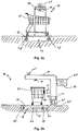
- FIG. 1 a vending machine 10 shows, in which the shopping cart 11 is pushed forward under the frame 12 and is pulled out backwards under the frame 12 after the payment process has been completed 2a and 2b a first view and a second view of a sales device 10 in a second embodiment, in which the shopping cart 11 is pushed under the sales device 10.
- the frame 12 projects laterally over the shopping cart 11 2a and 2b Vending device 10 shown is a passage arrangement.
- the support plate 13 is supported on four load cells 18. This gives the support plate 13 more stability and ensures a more accurate weighing result.
- the first Embodiment can be implemented with four load cells 18 and that the second embodiment can also be implemented with only one load cell 18.
- the data carrier 16 is attached to the side of the shopping cart 11 so that, provided the shopping cart 11 is in the rest position, it is at a defined distance from the sensor 15.
- the input / output unit 20 is as in FIG Fig. 2b shown attached to the side of the frame 12.
- the payment unit 30 is integrated in the input / output unit 20.
- 2a and 2b do not show a gripper for reasons of clarity, the person skilled in the art understands that the gripper can be attached to the support plate in the same way as in the first embodiment.
- An alternative possibility of defining a rest position is, for example, a stop at the end of the support plate 13 in the direction of travel, which is part of the support plate 13 and can be extended and lowered over the support plate. When the stop is extended, the operator pushes the front wheel of the shopping cart up to the stop. By lowering below the height of the support plate 13, the stop only allows the shopping cart 11 to continue when both verification and payment process have been successfully completed. If the gripper 17a, 17b or the stop is integrated in the support plate 13, no force shunt can occur and there are no disadvantages in determining the weight.
- Fig. 3a shows a vending device 40 in a third embodiment.
- This version is suitable for the contents of a shopping basket 41 ( Fig. 3b ) to verify.
- a frame 42 is designed such that it forms a support for the shopping basket 41, which is not on the floor but at an ergonomic height for the operator.
- the frame 42 comprises an upper part which protrudes above the shopping basket 41 when it is put down.
- the frame 42 holds at least one camera 44, which is positioned such that it can take a picture of the contents of the shopping basket 41 from an open side of the shopping basket 41.
- the sales device 40 further comprises a sensor 45, which is mounted in the frame 42 or in the support plate 43 and reads a unique identification number from a data carrier 46 of the shopping basket 41.
- Vending device 40 includes a scale.
- the support plate 43 forms the load plate of the balance and is mechanically connected to the force application side of a load cell 48 accommodated in the frame 42.
- the load cell 48 is connected to a weight value processing device 54, which determines a weight value of the shopping basket 41 from the signals of the load cell 48 and stores it in a weight value memory.
- the support plate 43 can be held by a plurality of load cells 48. Since a shopping basket 41 is not as heavy and not as large as a shopping cart 11 and the support plate 43 is accordingly smaller than in the first two embodiments, a load cell 48 is sufficient for determining the weight in a preferred embodiment.
- the weight value processing device 54 then forwards the weight value to a controller 52, which in turn is connected to a communication device 53.
- the controller 52 controls the processes in the vending device 40.
- the communication device 53 is connected to a network 55.
- the upper part of the frame 42 comprises an input / output unit 50.
- the input / output unit 50 can be integrated in the frame of the frame 42 and is, for example, a touchscreen.
- a payment unit 50a is attached to the frame.
- the payment unit 50a can also be integrated in the input / output unit 50.
- the payment unit 50a is used for cashless payment at the vending device 40.
- a release display device 51 is also attached to the frame 42 on the upper side.
- the display of the The first and / or second release indicator can be displayed, for example, in the form of a light signal.
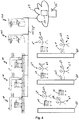
- Fig. 4 shows a system for self-checkout in a supermarket.
- customers 61 in the supermarket, who themselves become operators during the self-checkout on the sales devices 10, 40.
- the customers 61 go to the shelves 60 with a shopping cart 11 or a shopping basket 41 in order to remove corresponding products and place them in their shopping cart 11 or shopping basket 41.
- Each customer has a product scanner 62 on hand with which he scans each product before placing it in the shopping cart 11 or the shopping basket 41.
- Each product scanner 62 wirelessly transmits each scanned product and an identification number of the shopping cart 11 or the shopping basket 41 to which the product scanner 62 is assigned to a network 63. Both the product scanner 62 and the network 63 are able to communicate with one another wirelessly.
- the product scanner 62 and the network 63 are a local network with an adapted product scanner 62.
- the product scanner 62 is a smartphone on which a corresponding app is running.
- the smartphone 62 is connected to the network 63 via a public mobile radio network 65 or a WLAN of the supermarket 65.
- network 63 is a computing cloud, that is, a cloud network.
- the supermarket comprises one or more sales devices 10 which are suitable for self-checkout with a shopping cart 11 and which are shown in detail in FIGS Figures 1 , 2a and 2b are shown.
- the supermarket comprises one or more sales devices 40 which are suitable for self-checkout with a shopping basket 41 and which are shown in detail in FIG Fig. 3 are shown.
- the sales devices 10, 40 are connected to the computing cloud 63 via a network 25, 55.
- the computing cloud 63 comprises a verification unit 64, which from the sales device 10, 40 via the network 25, 55 images and weight values, which lead to an identification number belong to a shopping cart 11 or a shopping basket 41. For this identification number, the computing cloud 63 has received a list of products from the corresponding product scanners 62 via the wireless network 65 which should be in the shopping cart 11 or in the shopping basket 41.
- the verification unit 64 checks images and weight values that belong to a certain identification number with a list of products that are associated with this identification number. It is checked whether every product that can be inferred from the pictures and the weight values is also on the list of products.
- a plausibility test is carried out in the verification unit 64 as to whether the customer 61 has scanned in all products. If this is the case, the verification unit 64 generates an enable signal which is transmitted to the corresponding sales devices 10, 40 via the network 25, 55.
- Fig. 5 shows schematically a method for self-checkout in a supermarket.
- the method steps are carried out partly by the customer, partly by an inventive sales device 10, 40 and partly in an associated network 63, in particular in a computing cloud 63.
- the steps on the left are performed by the customer while shopping.
- the steps in the middle are carried out by the vending machine 10, 40.
- the steps on the right are performed by Computing Cloud 63.
- a customer takes a shopping cart 11 or Shopping basket 41 and scans its identification number with a product scanner 62. The customer thus assigns a shopping cart 11 or shopping basket 41 to his product scanner 62.
- the product scanner 63 is an RFID or NFC-capable smartphone and the data carrier 16, 46 on the shopping cart 11 or the shopping basket is an RFID or NFC data carrier.
- the scanning process in step 70 is carried out using this technology.
- the data carrier is a plate with a barcode or QR code and the scanning process takes place optically via the smartphone camera.
- step 71 the customer walks through the supermarket and takes the desired products from the shelves 60.
- the customer scans each product that he removes from the shelves 60 with the product scanner 62 and places it in his shopping cart 11 or shopping basket 41.
- the product scanner 62 transmits the scanned products in each case via a wireless network 65.
- a list of the scanned products is created in the network, in particular in the computing cloud 63, and assigned to the corresponding product scanner 62 and the identification number associated therewith. As soon as a customer has collected all the products that he would like to buy, he goes to a sales device 10, 40.
- the sales device 10, 40 automatically detects shopping cart 11 or shopping basket 41 in step 72.
- sales device 10, 40 automatically fixes shopping cart 11 or shopping basket 41 with a gripper 17a, 17b.
- the sales device 10, 40 automatically determines the unique identification number of the shopping cart 11 or the shopping basket 41 using a sensor 15, 45.
- the sales device 10, 40 automatically creates at least one image at least one camera 14, 44 from at least one open side of the shopping cart 11 or the shopping basket 41.
- step 76 the weight of the shopping cart 11 or the shopping basket 41 is determined with a load cell 18, 48 and an associated weight processing device 24, 54. Steps 74 to 76 can be carried out simultaneously. Their order can also be changed.
- the sales device 10, 40 sends the identification number, the images created and the determined weight value to a network, in particular a computing cloud 63, via a network 25, 55.
- the computing cloud 63 receives the transmitted data.
- a product list belonging to the identification number was created in the computing cloud 63, which is read out by the verification unit 64 from the memory of the computing cloud 63 in step 79.
- step 80 the purchase is verified in the verification unit 64 of the computing cloud 63.
- the product list with the products that should be expected in the shopping cart 11 or in the shopping basket 41 is compared with the received images and with the weight value.
- the verification unit 64 recognizes whether there are products in the shopping cart 11 or shopping basket 41 that are not on the product list. If a discrepancy is detected, an error message is generated which is sent to the vending device in step 81 and the self-checkout process must be terminated and the checkout process must be continued with the help of an employee of the supermarket.
- the verification unit sends a non-release for this purpose. However, if the verification unit 64 confirms in step 80 that the product list, the images and the weight value that belong to an identification number match, the verification unit 64 sends a release signal to the vending device 10, 40 via the network 25, 55 in step 81.
- step 82 the vending device 10, 40 receives a release signal from the computing cloud 63.
- step 83 the vending device 10, 40 displays the release to the operator and starts the payment process in step 84. If the payment process is successfully completed, the sales device 10, 40 displays a second release and optionally releases the shopping cart 11 or shopping basket 41 from the gripper. The customer is then able to leave the supermarket with his purchase.
- not every scanned article is sent to the computing cloud 63 over the network 65 in step 71.
- the list of the scanned articles is created in the product scanner 62.
- the computing cloud 63 requests in step 79 via the network 65 and receives the complete list from the product scanner 62.
- DSP digital signal processor
- ASIC application specific integrated circuit
- FPGA field programmable gate array
- ROM read only memory
- RAM random access memory
Landscapes
- Business, Economics & Management (AREA)
- Physics & Mathematics (AREA)
- General Physics & Mathematics (AREA)
- Accounting & Taxation (AREA)
- Finance (AREA)
- Strategic Management (AREA)
- General Business, Economics & Management (AREA)
- Engineering & Computer Science (AREA)
- Theoretical Computer Science (AREA)
- Cash Registers Or Receiving Machines (AREA)
Abstract
Description
- Die vorliegende Erfindung betrifft eine Verkaufsvorrichtung zum Selbst-Checkout in einem Supermarkt. Mit der Verkaufsvorrichtung wird der Inhalt eines Einkaufswagens oder Einkaufskorbes vor einem Bezahlvorgang verifiziert. Die Erfindung betrifft ferner ein System aus Verkaufsvorrichtungen, Einkaufswagen und/oder Einkaufkörben und einem Netzwerk sowie ein Verfahren zum Betrieb einer Verkaufsvorrichtung.
- Die
US 9 773 386 B2 - Aufgabe der Erfindung ist es eine Verkaufsvorrichtung zu schaffen, die den Checkout Prozess in einem Supermarkt vereinfacht und insbesondere den Prozess des Bezahlens im Falle von durch den Kunden selbst eingescannten Artikeln vereinfacht und automatisiert.
- Diese Aufgabe wird durch eine Verkaufsvorrichtung nach Anspruch 1, ein System zum Selbst-Checkout nach Anspruch 10 und ein Verfahren zum Betrieb einer Verkaufsvorrichtung nach Anspruch 11 gelöst.
- Erfindungsgemäß wird eine Verkaufsvorrichtung zum Selbst-Checkout von Waren in einem Ladengeschäft vorgeschlagen. Bei dem Ladengeschäft handelt es sich insbesondere um einen Supermarkt. Die Verkaufsvorrichtung umfasst eine Steuerung zum Steuern der Verkaufsvorrichtung. Die Verkaufsvorrichtung umfasst ferner eine Kommunikationsvorrichtung zum Empfangen von Daten aus einem Netzwerk und zum Senden von Daten in ein Netzwerk. Die Verkaufsvorrichtung umfasst mindestens eine Kamera zum Erstellen eines Bildes von mindestens einer Ansicht einer offenen Seite eines Einkaufswagens oder eines Einkaufskorbes. Die Verkaufsvorrichtung umfasst eine Auflageplatte, die dazu ausgebildet ist, dass der Einkaufswagen oder der Einkaufskorb darauf abgestellt werden kann. Im Falle einer Verkaufsvorrichtung für Einkaufswagen kann der Einkaufswagen auf die Auflageplatte aufgefahren werden. Sie ist somit weitestgehend bündig mit dem Fußboden und befindet sich zum Beispiel in einer von der Größe her angepassten Ausnehmung im Fußboden oder ist mit einer kleinen Rampe versehen. Im Fall einer Verkaufsvorrichtung für einen Einkaufskorb dient die Auflageplatte als Tisch auf einer Höhe, die einem Bediener erlaubt, den Korb ergonomisch angenehm auf der Auflageplatte abzustellen. Die Verkaufsvorrichtung umfasst einen Detektor. Der Detektor ist dazu ausgebildet, das Vorhandensein eines Einkaufswagens oder eines Einkaufskorbes auf der Auflageplatte zu detektiert. Bei dem Detektor handelt es sich in einer Ausführungsform um einen Kontaktschalter, eine Lichtschranke, ein optisches System, einen Laser- oder Ultraschall-Entfernungsmesser, einen Gewichtssensor oder ein magnetisches System. Des Weiteren umfasst die Verkaufsvorrichtung einen Sensor, der eine eindeutige Identifikationsnummer des Einkaufswagens oder des Einkaufskorbes ermittelt. In einer Ausführungsform ist die eindeutige Identifikationsnummer des Einkaufswagens oder des Einkaufskorbes auf einem Datenträger gespeichert, der sich am Einkaufswagen oder am Einkaufskorb befindet. Bei dem Datenträger handelt es sich in einer Ausführungsform um eine flache Platte, auf der ein Barcode oder QR-Code aufgedruckt ist oder um einen RFID- oder NFC-Datenträger. Der Datenträger ist im Falle eines Einkaufswagens in einer Ausführungsform am Wagenfuß, an der Front des Einkaufswagens oder an einer Seitenwand des Einkaufswagens angebracht. Der Datenträger ist im Fall eines Einkaufskorbes in einer Ausführungsform am Boden oder an der Seite des Einkaufskorbes angebracht. Der Sensor ermittelt die Identifikationsnummer automatisch, wenn der Detektor einen Einkaufswagen oder einen Einkaufskorb auf der Auflageplatte detektiert. Bei dem Sensor handelt es sich in einer Ausführungsform um einen Barcode-Scanner, um einen QR-Code-Scanner oder um eine RFID- oder NFC-Lesevorrichtung. In einer Ausführungsform handelt es sich bei dem Sensor um eine RFID- oder NFC-Lesevorrichtung, die zeitgleich das Vorhandensein eines Einkaufswagens oder eines Einkaufskorbes auf der Auflageplatte detektiert und den RFID- oder NFC-Datenträger des Einkaufswagens oder des Einkaufskorbes ausliest. Somit sind in dieser Ausführungsform Detektor und Sensor in einem einzigen Bauteil realisiert.
- In einer Ausführungsform weist die Auflageplatte eine Ruheposition für den Einkaufswagen oder den Einkaufskorb auf. Der Sensor ist geometrisch im Vergleich zur Auflageplatte derart in der Verkaufsvorrichtung angebracht, dass der Sensor die eindeutige Identifikationsnummer von dem Datenträger des Einkaufswagens oder Einkaufskorbes automatisch ausliest, sobald der Einkaufswagen oder der Einkaufskorb die Ruheposition auf der Auflageplatte erreicht hat. In anderen Worten, befindet sich ein Einkaufswagen oder ein Einkaufskorb in der Ruheposition auf der Auflageplatte, so sind sich Sensor und Datenträger derart nahe, dass der Sensor den Datenträger auslesen kann. Ist der Datenträger zum Beispiel ein Barcode oder QR-Code, so befindet sich der Sensor dann in einer Entfernung zum Barcode oder QR-Code, dass ein Lesen des Codes möglich ist. Ist der Datenträger ein RFID- oder NFC-Datenträger, so befindet sich der Sensor nahe genug am Datenträger, um ihn auszulesen.
- In einer Ausführungsform umfasst die Verkaufsvorrichtung eine Waage zum Wiegen eines Einkaufswagens oder eines Einkaufskorbes. Eine Lastplatte der Waage ist durch die Auflageplatte ausgebildet. Die Waage ermittelt einen Gewichtswert, wenn der Detektor einen Einkaufswagen oder einen Einkaufskorb auf der Auflageplatte detektiert. In einer Ausführungsform ermittelt die Waage den Gewichtswert automatisch, wenn der Einkaufswagen oder der Einkaufskorb durch den Detektor detektiert wird und/oder sobald der Einkaufswagen oder der Einkaufskorb die Ruheposition auf der Auflageplatte erreicht. Die Waage speichert den Gewichtswert in einen Gewichtswertspeicher.
- In einer Ausführungsform umfasst die Verkaufsvorrichtung eine Lesevorrichtung, die einen Gewichtswert aus einem Einkaufswagen oder einem Einkaufskorb, der auf der Auflageplatte abgestellt ist, ausliest und an den Gewichtswertspeicher übergibt. Ein Einkaufswagen oder ein Einkaufskorb hat in dieser Ausführungsform eine eingebaute Waage und bestimmt den Gewichtswert der Gegenstände, die sich im Einkaufswagen oder im Einkaufskorb befinden. Ein Einkaufswagen oder ein Einkaufskorb in dieser Ausführungsform hat einen elektronischen Datenträger, zum Beispiel einen RFID- oder NFC-Datenträger, worauf der Gewichtswert abgespeichert ist. Die Lesevorrichtung der Verkaufsvorrichtung liest den Gewichtswert von diesem Datenträger aus. In einer Ausführungsform ist die Lesevorrichtung der Sensor der Verkaufsvorrichtung, die sowohl den Gewichtswert wie auch die Identifikationsnummer des Einkaufswagens oder des Einkaufskorbes ausliest.
- In einer Ausführungsform sendet die Kommunikationseinrichtung die Identifikationsnummer des Einkaufswagens oder des Einkaufskorbes, mindestens ein Kamerabild mindestens einer offenen Seite des Einkaufswagens oder des Einkaufskorbes und/oder das Gewicht aus dem Gewichtswertspeicher an das Netzwerk. Die Kommunikationsvorrichtung empfängt vom Netzwerk ein zur Identifikationsnummer zugehöriges Freigabesignal. Das Netzwerk ist in einer Ausführungsform ausgebildet als ein Intranet in einem Supermarkt, in dem sich die Verkaufsvorrichtung befindet und die Identifikationsnummer und mindestens ein Kamerabild und/oder das Gewicht werden an einen Server gesendet, der eine Verifikationseinheit umfasst und ein Freigabesignal erzeugt. In einer Ausführungsform ist das Netzwerk eine Computing Cloud, das heißt ein Cloud Netzwerk, an die die Identifikationsnummer und mindestens ein Kamerabild und/oder der Gewichtswert gesendet werden und die ein Freigabesignal erzeugt.
- In einer Ausführungsform umfasst die Verkaufsvorrichtung eine Bezahleinheit zum Bezahlen, insbesondere zum bargeldlosen Bezahlen.
- In einer Ausführungsform umfasst die Verkaufsvorrichtung eine Freigabeeinheit. Die Freigabeeinheit steuert einen Freigabeindikator, der eine Freigabe anzeigt, falls ein zur Identifikationsnummer zugehöriges Freigabesignal vom Netzwerk empfangen wurde. Der Freigabeindikator zeigt eine Nicht-Freigabe an, falls ein zur Identifikationsnummer zugehöriges Freigabesignal nicht empfangen wurde. In einer Ausführungsform wird der Freigabeindikator auf der Bezahleinheit angezeigt.
- In einer Ausführungsform steuert die Freigabeeinheit einen zweistufigen Freigabeindikator. Die erste Stufe des Freigabeindikators zeigt eine Freigabe an, falls ein zur Identifikationsnummer zugehöriges Freigabesignal vom Netzwerk empfangen wurde. Die erste Stufe des Freigabeindikators zeigt eine Nicht-Freigabe an, falls ein zur Identifikationsnummer zugehöriges Freigabesignal nicht empfangen wurde. Die zweite Stufe des Freigabeindikators zeigt eine Freigabe an, falls ein Bezahlvorgang erfolgreich abgeschlossen wurde. Die zweite Stufe des Freigabeindikators zeigt eine Nicht-Freigabe an, falls ein Bezahlvorgang nicht erfolgreich abgeschlossen wurde. Mindestens einer der beiden Freigabeindikatoren wird auf der Bezahleinheit angezeigt. In einer Ausführungsform ist die Bezahleinheit ein Terminal zum bargeldlosen Bezahlen mittels Kreditkarte oder EC Karte. Nach erfolgreicher elektronischer Bezahlung wird der Abschluss der Transaktion in der Bezahleinheit angezeigt. In einer Ausführungsform ist die Bezahleinheit eine Vorrichtung zum Mobilen Bezahlen, zum Beispiel mit einem Smartphone und einer entsprechenden App. In einer Ausführungsform erlaubt eine App des Smartphones sowohl das Einscannen der Produkte während des Einkaufs sowie das Mobile Bezahlen.
- In einer Ausführungsform wird die Freigabe durch das Aufleuchten eines Leuchtmittels angezeigt. Die Nicht-Freigabe wird dadurch angezeigt, dass das Leuchtmittel nicht aufleuchtet. In einer Ausführungsform werden Freigabe und Nicht-Freigabe durch Symbole oder Text auf einem Bedienfeld, einer Anzeigevorrichtung oder einer Ein/Ausgabeeinrichtung der Verkaufsvorrichtung oder der Bezahleinheit angezeigt.
- In einer Ausführungsform umfasst die Verkaufsvorrichtung einen Greifer, der den Einkaufswagen oder den Einkaufskorb auf der Auflageplatte automatisch fixiert, wenn der Einkaufswagen oder Einkaufskorb in der Verkaufsvorrichtung durch den Detektor detektiert wird. In einer Ausführungsform fixiert der Greifer den Einkaufswagen oder den Einkaufskorb in der Ruheposition auf der Auflageplatte. Der Greifer gibt den Einkaufswagen oder Einkaufskorb erst frei, wenn die Freigabeeinheit ein zur Identifikationsnummer zugehöriges Freigabesignal vom Netzwerk empfangen hat und/oder wenn die Bezahleinheit das erfolgreiche Beenden eines Bezahlvorgangs festgestellt hat.
- Erfindungsgemäß wird ein System zum Selbst-Checkout von Waren in einem Ladengeschäft vorgeschlagen. In einer Ausführungsform ist das Ladengeschäft ein Supermarkt. Das System umfasst eine Vielzahl von Einkaufswagen und/oder Einkaufskörben. Das System umfasst ferner mindestens eine erfindungsgemäße Verkaufsvorrichtung. Jede Verkaufsvorrichtung ist über deren Kommunikationsvorrichtung mit einem Netzwerk verbunden. In einer Ausführungsform ist das Netzwerk eine Computing Cloud, das heißt ein Cloud Netzwerk. In einer Ausführungsform ist das Netzwerk ein lokales Netzwerk des Ladengeschäfts. In einer Ausführungsform ist das Netzwerk ein öffentliches Netzwerk. Das Netzwerk umfasst eine Verifikationseinheit, die ein Freigabesignal erzeugt, falls eine zu einer von der Verkaufsvorrichtung gesendeten Identifikationsnummer zugehörige Liste von Waren mit zugehörigen von der Verkaufsvorrichtung übertragenen Bildern und Gewichtswerten übereinstimmt. Die Waren, die ein Bediener während seines Einkaufs im Ladengeschäft auswählt, scannt er mithilfe eines mobilen Terminals ein. In einer Ausführungsform ist das mobile Terminal ein Smartphone mit einer entsprechenden App. Dieses mobile Terminal sendet die Information über die eingescannten Waren, einzeln oder als Liste, über ein Netzwerk an die Verifikationseinheit. So wird eine Liste von Waren generiert, die sich in dem Einkaufswagen oder in dem Einkaufskorb befinden müssten. In einer Ausführungsform ist das Netzwerk ein Mobilfunknetz, in dem das Smartphone angemeldet ist.
- Erfindungsgemäß wird ein Verfahren zum Betrieb einer Verkaufsvorrichtung zum Selbst-Checkout in einem Ladengeschäft, insbesondere in einem Supermarkt, vorgeschlagen. In einem Schritt wird ein Einkaufswagen oder ein Einkaufskorb auf einer Auflageplatte mit einem Detektor detektiert. In einem weiteren Schritt wird eine eindeutige Identifikationsnummer des Einkaufswagens oder des Einkaufskorbes mit einem Sensor ermittelt. In einer Ausführungsform werden die beiden Schritte zeitgleich, insbesondere mit dem gleichen Sensor ausgeführt. In einem weiteren Schritt wird mindestens ein Bild von mindestens einer Ansicht einer offenen Seite des Einkaufswagens oder des Einkaufskorbes mit einer Kamera erstellt. In einem weiteren Schritt sendet eine Kommunikationsvorrichtung die eindeutige Identifikationsnummer und das mindestens eine Bild der mindestens einen offenen Seite des Einkaufswagens oder des Einkaufskorbes an ein Netzwerk. In einer Ausführungsform ist das Netzwerk eine Computing Cloud, das heißt ein Cloud Netzwerk. In einer Ausführungsform ist das Netzwerk ein lokales Netzwerk. In einer Ausführungsform ist das Netzwerk ein öffentliches Netzwerk. In einem weiteren Schritt empfängt die Kommunikationsvorrichtung aus dem Netzwerk ein zu der eindeutigen Identifikationsnummer zugehöriges Freigabesignal.
- Das Verfahren hat den Vorteil, dass das Erkennen und verifizieren des Inhalts des Einkaufswagens oder des Einkaufskorbes automatisch abläuft. Der Bediener muss nicht den Einkaufswagen oder den Einkaufskorb an der Verkaufsvorrichtung anmelden. Er muss auch nicht den Produktscanner mit der Verkaufsvorrichtung synchronisieren. Somit ist das Verfahren nicht fehleranfällig und zeiteffizient.
- In einer Ausführungsform umfasst das Verfahren das automatische Ermitteln eines Gewichtswertes des Einkaufswagens oder des Einkaufskorbes mit einer Waage, deren Lastplatte die Auflageplatte ist.
- In einer Ausführungsform umfasst das Verfahren das Auslesen eines Gewichtswertes aus einem Datenträger des Einkaufswagens oder dem Einkaufskorbes, der auf der Auflageplatte abgestellt ist.
- In einer Ausführungsform umfasst das Verfahren das Anzeigen einer Freigabe mit einem zweistufigen Freigabeindikator, wobei die erste Stufe des Freigabeindikators eine Freigabe anzeigt, falls ein zur Identifikationsnummer zugehöriges Freigabesignal vom Netzwerk empfangen wurde und die erste Stufe des Freigabeindikators eine Nicht-Freigabe anzeigt, falls ein zur Identifikationsnummer zugehöriges Freigabesignal nicht empfangen wurde. Die zweite Stufe des Freigabeindikators zeigt eine Freigabe an, falls ein Bezahlvorgang erfolgreich abgeschlossen wurde und die zweite Stufe des Freigabeindikators zeigt eine Nicht-Freigabe an, falls ein Bezahlvorgang nicht erfolgreich abgeschlossen wurde. In einer Ausführungsform umfasst das Verfahren das Anzeigen einer Freigabe mit einem einfachen Freigabeindikator, der nur die erste Stufe anzeigt.
- In einer Ausführungsform umfasst das Verfahren das automatische Fixieren des Einkaufswagens oder des Einkaufskorbes auf der Auflageplatte mit einem Greifer. Der Einkaufswagen oder der Einkaufskorb wird insbesondere in einer Ruheposition auf der Auflageplatte fixiert. In einem Schritt wird der Einkaufswagen oder der Einkaufskorb durch den Greifer freigegeben, wenn die Freigabeeinheit ein zur Identifikationsnummer zugehöriges Freigabesignal vom Netzwerk empfangen hat. In einer Ausführungsform wird der Einkaufswagen oder der Einkaufskorb erst freigegeben, wenn die Freigabeeinheit ein zur Identifikationsnummer zugehöriges Freigabesignal vom Netzwerk empfangen hat und wenn die Bezahleinheit das erfolgreiche Beenden eines Bezahlvorgangs festgestellt hat.
- Einige Ausführungsformen der Erfindung sind in den Zeichnungen beispielhaft gezeigt und nachfolgend beschrieben. Es zeigen, jeweils in schematischer Darstellung:
- Fig. 1
- eine erfindungsgemäße Verkaufsvorrichtung für einen Einkaufswagen in einer ersten Ausführungsform,
- Fig. 2
- a und b: eine erfindungsgemäße Verkaufsvorrichtung für einen Einkaufswagen in einer zweiten Ausführungsform,
- Fig. 3
- a: eine erfindungsgemäße Verkaufsvorrichtung nach einer dritten Ausführungsform für einen Einkaufskorb, und
- b: einen Einkaufskorb für eine erfindungsgemäße Verkaufsvorrichtung,
- Fig. 4
- ein System zum Selbst-Checkout in einem Ladengeschäft, und
- Fig. 5
- ein erstes Verfahren zum Betrieb einer erfindungsgemäßen Verkaufsvorrichtung.
-
Figur 1 zeigt eine erfindungsgemäße Verkaufsvorrichtung 10 in einer ersten Ausführungsform. Die Verkaufsvorrichtung 10 umfasst ein Gestell 12 unter das ein Einkaufswagen 11 geschoben werden kann. Der Einkaufswagen 11 hat eine definierte Position (Ruheposition) unter dem Gestell 12 auf einer Auflageplatte 13. Die Auflageplatte 13 ist eine Lastplatte einer Waage und mit der Krafteinleitungsseite einer oder mehrerer Wägezellen 18 mechanisch verbunden. Die Waage bestimmt das Gesamtgewicht des Einkaufswagens 11 mit seinem Inhalt. Das Gestell 12 umfasst weiter mindestens eine Kamera 14, die zum Erstellen von mindestens eines Bildes einer Ansicht einer offenen Seite des Einkaufswagens 11 ausgebildet ist. Bei einem Einkaufswagen 11 ist normalerweise die obere Seite offen. Eine offene Seite im Sinne dieser Offenbarung ist jedoch auch zum Beispiel ein Seitenteil des Einkaufswagens, dass aus transparentem Material besteht. Im Rahmen der Erfindung soll als offene Seite ebenfalls gelten, wenn der Einkaufswagen aus einem grobmaschigen Metallgitter besteht, durch das hindurch eine Bildaufnahme des Inhalts des Einkaufswagens gemacht werden kann. Nicht als offene Seite ist im Rahmen dieser Offenbarung zu verstehen, wenn die Seite eines Einkaufswagens aus nicht transparentem Kunststoff besteht oder durch eine nicht transparente Werbetafel verdeckt ist. Das Gestell 12 umfasst einen Sensor 15, der eine eindeutige Identifikationsnummer des Einkaufswagens 11 ermittelt. Die eindeutige Identifikationsnummer ist fest an einem Datenträger 16 des Einkaufswagens 11 angebracht. Ist der Datenträger 16 zum Beispiel eine flache Platte auf der ein Barcode oder QR-Code aufgebracht ist, so ist der Sensor 15 ein Barcode Lesegerät oder QR-Code Lesegerät und befindet sich, wenn sich der Einkaufswagen 11 in der Ruheposition befindet, in einer Entfernung zum Barcode oder QR-Code, die das Lesen des Codes erlaubt. Ist der Datenträger 16 ein RFID- oder NFC-Datenträger, so ist der Sensor 15 ein RFID-Lesegerät oder NFC-Lesegerät und befindet nahe genug am Datenträger 16, um ihn auszulesen, wenn der Einkaufswaagen sich in der Ruheposition befindet. Das Gestell 12 umfasst einen Detektor, der das Vorhandensein eines Einkaufswagens 11 detektiert. Sowohl der Sensor 15 wie auch die Wägezelle 18 können als Detektor dienen. Des Weiteren kann der Detektor als separater Detektor wie zum Beispiel eine Lichtschranke ausgebildet sein. Die Verkaufsvorrichtung 10 umfasst einen Greifer 17a, 17b, der den Einkaufswagen auf der Auflageplatte 13 automatisch fixiert und in der Ruheposition hält, sobald der Detektor einen Einkaufswagen auf der Auflageplatte 13 detektiert. Die Wägezelle 18 ist mit einer Gewichtswertverarbeitungsvorrichtung 24 verbunden, die aus den Signalen der Wägezelle 18 oder der Wägezellen 18 einen Gewichtswert des Einkaufswagens 11 ermittelt. Die Gewichtswertverarbeitungsvorrichtung 24 umfasst einen Gewichtswertspeicher zum Speichern des Gewichtswertes. Die mindestens eine Kamera 14, der Sensor 15 und die Gewichtswertverarbeitungsvorrichtung 24 sind mit einer Steuerung 22 verbunden und übergeben die ermittelten Daten an die Steuerung 22. Die Steuerung 22 ist mit einer Kommunikationsvorrichtung 23 verbunden, über die die Steuerung 22 Daten wie Bilder, Identifikationsnummer und Gewicht an ein Netzwerk 25 übermittelt und mindestens ein Freigabesignal vom Netzwerk 25 empfängt. Die Verkaufsvorrichtung umfasst eine Ein-/Ausgabeeinheit 20, mit der ein Bediener mit der Verkaufsvorrichtung 10 interagieren kann. Die Ein-/Ausgabeeinheit 20 umfasst ebenfalls eine Bezahleinheit, an der vorzugsweise bargeldlos bezahlt werden kann. Auf der Ein-/Ausgabeeinheit 20 zeigt ein erster Freigabeindikator eine Freigabe an, falls ein zur Identifikationsnummer zugehöriges Freigabesignal vom Netzwerk 25 empfangen wird. Das Netzwerk schickt ein derartiges Freigabesignal, falls die von der Kommunikationseinheit 23 ins Netzwerk 25 gesendeten Daten, bestehend aus Gewicht, einem oder mehreren Bildern von offenen Seiten des Einkaufswagens 11 und Identifikationsnummer, bei einem in dem Netzwerk 25, 63, zum Beispiel in einem Cloud-Netzwerk (Computing Cloud) 25, 63, ausgeführten Verifikationsprozess verifiziert werden konnten. Die Ein-/Ausgabeeinheit 20 zeigt mit einem zweiten Freigabeindikator eine Freigabe an, falls ein Bezahlvorgang erfolgreich abgeschlossen wurde. Werden die oben genannten Bedingungen nicht erfüllt, so wird der entsprechende erste und/oder zweite Freigabeindikator nicht angezeigt oder diese Freigabeindikatoren zeigen eine Nicht-Freigabe an. Die Freigabeeinheit ist Teil der Steuerung 22. Die Anzeige des ersten und/oder zweiten Freigabeindikators kann zusätzlich oder alternativ auch durch eine Freigabeanzeigevorrichtung 21, zum Beispiel in Form eines Lichtsignals, angezeigt werden. Die Freigabeanzeigevorrichtung 21 ist am Gestell 12 angebracht. Hat sowohl eine erfolgreiche Verifikation im Netzwerk 25, 63 stattgefunden, wie auch ein erfolgreicher Bezahlvorgang, so öffnet gleichzeitig mit Anzeige des zweiten Freigabeindikators die Steuerung 22 den Greifer 17a, 17b und gibt den Einkaufswagen 11 wieder frei. Der Bediener kann ab diesem Zeitpunkt den Einkaufswagen 11 unter dem Gestell 12 hervorziehen und den Supermarkt verlassen. Das Festhalten des Einkaufswagens 11 unter dem Gestell 12 mithilfe des Greifers 17a, 17b führt dazu, dass der Kunde nicht aus Versehen schon den Einkaufswagen 11 Richtung Ausgang des Supermarkts schiebt, solange der Verifikationsprozess oder der Bezahlvorgang noch nicht abgeschlossen ist. - Während
Fig. 1 eine Verkaufsvorrichtung 10 zeigt, bei der der Einkaufswagen 11 vorwärts unter das Gestell 12 geschoben wird und nach Abschluss des Bezahlvorgangs rückwärts unter dem Gestell 12 hervorgezogen wird, zeigenFig. 2a und 2b eine erste Ansicht und eine zweite Ansicht von einer Verkaufsvorrichtung 10 in einer zweiten Ausführungsform, bei der der Einkaufswagen 11 unter der Verkaufsvorrichtung 10 durchgeschoben wird. Das Gestell 12 ragt seitlich über den Einkaufswagen 11. Bei der inFig. 2a und 2b gezeigten Verkaufsvorrichtung 10 handelt es sich um eine Durchfahrtsanordnung. Um Wiederholungen zu vermeiden, wird bei der Beschreibung der zweiten Ausführungsform im Folgenden nur noch auf die Unterschiede im Vergleich zur ersten Ausführungsform eingegangen. Für die weiteren Merkmale wird auf die Beschreibung zuFig. 1 verwiesen. -
Fig. 2a und 2b zeigen beispielhaft, dass die Auflageplatte 13 auf vier Wägezellen 18 abgestützt ist. Dies gibt der Auflageplatte 13 mehr Stabilität und sorgt für ein genaueres Wiegeergebnis. Der Fachmann versteht, dass auch die erste Ausführungsform mit vier Wägezellen 18 umgesetzt werden kann und dass auch die zweite Ausführungsform mit nur einer Wägezelle 18 umgesetzt werden kann. In der zweiten Ausführungsform ist der Datenträger 16 seitlich am Einkaufswagen 11 angebracht, so das er, sofern sich der Einkaufswagen 11 in der Ruheposition befindet, einen definierten Abstand zum Sensor 15 hat. Die Ein-/Ausgabeeinheit 20 ist wie inFig. 2b gezeigt seitlich am Gestell 12 angebracht. Die Bezahleinheit 30 ist in die Ein-/Ausgabeeinheit 20 integriert. Der Bediener schieb den Einkaufswagen 11 seitlich unter das Gestell 12 und die Ein-/Ausgabeeinheit 20 befindet sich dann für den Bediener in einer ergonomischen Position.Fig. 2a und 2b zeigen der Übersichtlichkeit wegen keinen Greifer, wobei der Fachmann versteht, dass der Greifer gleich wie in der ersten Ausführungsform auf der Auflageplatte angebracht sein kann. Eine alternative Möglichkeit eine Ruheposition zu definieren ist zum Beispiel in Fahrtrichtung am Ende der Auflageplatte 13 ein Anschlag, der Teil der Auflageplatte 13 ist und über die Auflageplatte ausgefahren und abgesenkt werden kann. Bei ausgefahrenem Anschlag schiebt der Bediener das Vorderrad des Einkaufswagens bis zu dem Anschlag. Der Anschlag gibt durch ein Absenken unter die Höhe der Auflageplatte 13 die Weiterfahrt des Einkaufswagens 11 erst dann frei, wenn sowohl Verifikation als auch Bezahlvorgang erfolgreich abgeschlossen sind. Ist der Greifer 17a, 17b oder der Anschlag in die Auflageplatte 13 integriert, so kann kein Kraftnebenschluss entstehen und es entstehen keine Nachteile bei der Gewichtsbestimmung. -
Fig. 3a zeigt eine Verkaufsvorrichtung 40 in einer dritten Ausführungsform. Diese Ausführung ist geeignet, um den Inhalt eines Einkaufskorbes 41 (Fig. 3b ) zu verifizieren. Ein Gestell 42 ist derart ausgebildet, dass es eine Auflage für den Einkaufskorb 41 bildet, die sich nicht auf dem Boden, sondern auf einer für den Bediener ergonomischen Höhe befindet. Das Gestell 42 umfasst einen oberen Teil der über den abgestellten Einkaufskorb 41 ragt. Im Gestell ist eine Auflageplatte 43 ausgebildet, auf der der Einkaufskorb 41 mit seiner Unterseite 57 abgestellt werden kann. Das Gestell 42 haltert mindestens eine Kamera 44, die derart positioniert ist, dass sie von einer offenen Seite des Einkaufskorbes 41 ein Bild des Inhalts des Einkaufskorb 41 machen kann. Die Verkaufsvorrichtung 40 umfasst ferner einen Sensor 45, der im Gestell 42 oder in der Auflageplatte 43 angebracht ist, und eine eindeutige Identifikationsnummer aus einem Datenträger 46 des Einkaufskorb 41 ausliest. - Die Verkaufsvorrichtung 40 umfasst eine Waage. Die Auflageplatte 43 bildet die Lastplatte der Waage und ist mechanisch mit der Krafteinleitungsseite einer im Gestell 42 untergebrachten Wägezelle 48 verbunden. Die Wägezelle 48 ist mit einer Gewichtswertverarbeitungsvorrichtung 54 verbunden, die aus den Signalen der Wägezelle 48 einen Gewichtswert des Einkaufskorbes 41 ermittelt und in einem Gewichtswertspeicher speichert. Auch in dieser Ausführungsform kann die Auflageplatte 43 von mehreren Wägezellen 48 gehalten sein. Da ein Einkaufskorb 41 nicht so schwer und nicht so groß ist wie ein Einkaufswagen 11 und die Auflageplatte 43 dementsprechend kleiner ausgestaltet ist als in den ersten beiden Ausführungsformen, ist eine Wägezelle 48 zur Gewichtsbestimmung in einer bevorzugten Ausführungsform ausreichend. Die Gewichtswertverarbeitungsvorrichtung 54 gibt denn Gewichtswert an eine Steuerung 52 weiter, die ihrerseits mit einer Kommunikationsvorrichtung 53 verbunden ist. Die Steuerung 52 steuert die Abläufe in der Verkaufsvorrichtung 40. Die Kommunikationsvorrichtung 53 ist mit einem Netzwerk 55 verbunden. Der obere Teil des Gestells 42 umfasst eine Ein-/Ausgabeeinheit 50. Die Ein-/Ausgabeeinheit 50 kann in den Rahmen des Gestells 42 integriert sein und ist zum Beispiel ein Touchscreen. An dem Gestell ist eine Bezahleinheit 50a angebracht. Die Bezahleinheit 50a kann auch in die Ein-/Ausgabeeinheit 50 integriert sein. Die Bezahleinheit 50a dient dem bargeldlosen Bezahlen an der Verkaufsvorrichtung 40. An dem Gestell 42 auf der Oberseite ist ferner eine Freigabeanzeigevorrichtung 51 angebracht. Die Anzeige des ersten und/oder zweiten Freigabeindikators kann zum Beispiel in Form eines Lichtsignals angezeigt werden.
-
Fig. 4 zeigt ein System zum Selbst-Checkout in einem Supermarkt. Im Supermarkt sind eine Vielzahl von Kunden 61 vorhanden, die beim Selbst-Checkout an den Verkaufsvorrichtungen 10, 40 selbst zu Bedienern werden. Die Kunden 61 gehen mit einem Einkaufswagen 11 oder einem Einkaufskorb 41 an die Regale 60, um entsprechende Produkte zu entnehmen und sie in ihren Einkaufswagen 11 oder Einkaufskorb 41 zu legen. Dabei hat jeder Kunde einen Produktscanner 62 zur Hand, mit dem er jedes Produkt einscannt, bevor er es in den Einkaufswagen 11 oder den Einkaufskorb 41 legt. Jeder Produktscanner 62 übermittelt drahtlos jedes eingescannte Produkt sowie eine Identifikationsnummer des Einkaufswagens 11 oder des Einkaufskorbes 41, dem der Produktscanner 62 zugeordnet ist, an ein Netzwerk 63. Sowohl Produktscanner 62 wie auch Netzwerk 63 sind in der Lage miteinander drahtlos zu kommunizieren. Der Produktscanner 62 und das Netzwerk 63 sind in einer Ausführungsform ein lokales Netzwerk mit einem angepassten Produktscanner 62. In einer Ausführungsform ist der Produktscanner 62 ein Smartphone, auf dem eine entsprechende App läuft. Das Smartphone 62 ist über ein öffentliches Mobilfunknetz 65 oder ein WLAN des Supermarkts 65 mit dem Netzwerk 63 verbunden. In einer Ausführungsform ist das Netzwerk 63 eine Computing Cloud, das heißt ein Cloud Netzwerk. Der Supermarkt umfasst eine oder mehrere Verkaufsvorrichtungen 10, die für einen Selbst-Checkout mit einem Einkaufswagen 11 geeignet sind und die im Detail in denFiguren 1 ,2a und 2b gezeigt sind. Der Supermarkt umfasst alternativ oder zusätzlich eine oder mehrere Verkaufsvorrichtungen 40, die für den Selbst-Checkout mit einem Einkaufskorb 41 geeignet sind und die im Detail inFig. 3 gezeigt sind. Die Verkaufsvorrichtungen 10, 40 sind über ein Netzwerk 25, 55 mit der Computing Cloud 63 verbunden. Die Computing Cloud 63 umfasst eine Verifikationseinheit 64, die von den Verkaufsvorrichtung 10, 40 über das Netzwerk 25, 55 Bilder und Gewichtswerte, die zu einer Identifikationsnummer eines Einkaufswagens 11 oder eines Einkaufskorbes 41 gehören, übermittelt bekommt. Zu dieser Identifikationsnummer hat die Computing Cloud 63 über das drahtlose Netzwerk 65 von den entsprechenden Produktscannern 62 eine Liste von Produkten übermittelt bekommen, die sich im Einkaufswagen 11 oder im Einkaufskorb 41 befinden sollten. Die Verifikationseinheit 64 überprüft Bilder und Gewichtswerte, die einer gewissen Identifikationsnummer zugehören, mit einer Liste von Produkten, die mit dieser Identifikationsnummer assoziiert sind. Dabei wird geprüft, ob jedes Produkt, auf das aufgrund der Bilder und der Gewichtswerte rückgeschlossen werden kann, sich auch auf der Liste der Produkte befindet. Anders ausgedrückt wird ein Plausibilitätstest in der Verifikationseinheit 64 gemacht, ob der Kunde 61 alle Produkte eingescannt hat. Ist dies der Fall, so erzeugt die Verifikationseinheit 64 ein Freigabesignal, das über das Netzwerk 25, 55 an die entsprechende Verkaufsvorrichtungen 10, 40 übertragen wird. -
Fig. 5 zeigt schematisch ein Verfahren zum Selbst-Checkout in einem Supermarkt. Die Verfahrensschritte werden teileweise vom Kunden, teilweise von einer erfinderischen Verkaufsvorrichtung 10, 40 und teilweise in einem dazugehörigen Netzwerk 63, insbesondere in einer Computing Cloud 63, ausgeführt. Die Schritte auf der linken Seite werden vom Kunden während des Einkaufs ausgeführt. Die Schritte in der Mitte werden von der Verkaufsvorrichtung 10, 40 ausgeführt. Die Schritte auf der rechten Seite werden von der Computing Cloud 63 ausgeführt. - Beim Selbst-Checkout in einem Supermarkt ist der Kunde dafür zuständig, seine Einkäufe selbst aus den Regalen 60 zu nehmen, sie einzuscannen, das heißt die Produkte selbst zu erfassen und zum Abschließen des Einkaufs die Produkte an einer Verkaufsvorrichtung 10, 40 zum Selbst-Checkout selbst zu verifizieren und zu bezahlen. Der Supermarkt kann somit auf Kassenpersonal verzichten. Der Kunde ersetzt das Kassenpersonal und ist somit selbst Bediener der Selbst-Checkout Verkaufsvorrichtung 10, 40. In einem ersten Schritt 70 nimmt sich ein Kunde einen Einkaufswagen 11 oder Einkaufskorb 41 und scannt dessen Identifikationsnummer mit einem Produktscanner 62 ein. Somit ordnet der Kunde einen Einkaufswagen 11 oder Einkaufskorb 41 seinem Produktscanner 62 zu. In einer Ausführungsform ist der Produktscanner 63 ein RFID oder NFC fähiges Smartphone und der Datenträger 16, 46 an dem Einkaufswagen 11 oder dem Einkaufskorb ist ein RFID- oder NFC-Datenträger. Der Einscanvorgang in Schritt 70 erfolgt über diese Technologie. In einer Ausführungsform ist der Datenträger ein Platte mit einem Barcode oder QR-Code und der Einscanvorgang erfolgt optisch über die Smartphone Kamera.
- Alle während des Verkaufsvorgangs mit diesem Produktscanner 62 eingescannte Produkte werden der Identifikationsnummer des Einkaufswagens 11 oder des Einkaufskorbes 41 zugeordnet. Im Schritt 71 geht der Kunde durch den Supermarkt und nimmt sich die gewünschten Produkte aus den Regalen 60. Der Kunde scannt jedes Produkt, das er aus den Regalen 60 entnimmt, mit dem Produktscanner 62 ein und legt es in seinen Einkaufswagen 11 oder Einkaufskorb 41. Der Produktscanner 62 übermittelt jeweils über ein drahtloses Netzwerk 65 die eingescannten Produkte. Eine Liste der eingescannten Produkte wird in dem Netzwerk, insbesondere in der Computing Cloud 63, erstellt und dem entsprechenden Produktscanner 62 und der damit assoziierten Identifikationsnummer zugeordnet. Sobald ein Kunde alle Produkte, die einkaufen möchte, eingesammelt hat, begibt er sich zu einer Verkaufsvorrichtung 10, 40. Er schiebt den Einkaufswagen 11 auf die Auflageplatte 13 der Verkaufsvorrichtung 10 oder legt den Einkaufskorb 41 auf die Auflageplatte 43 der Verkaufsvorrichtung 40. Die Verkaufsvorrichtung 10, 40 detektiert automatisch den Einkaufswagen 11 oder den Einkaufskorb 41 in Schritt 72. Im optionalen Schritt 73 fixiert die Verkaufsvorrichtung 10, 40 den Einkaufswagen 11 oder den Einkaufskorb 41 mit einem Greifer 17a, 17b automatisch. In Schritt 74 ermittelt die Verkaufsvorrichtung 10, 40 mit einem Sensor 15, 45 automatisch die eindeutige Identifikationsnummer des Einkaufswagens 11 oder des Einkaufskorbes 41. Im Schritt 75 erstellt die Verkaufsvorrichtung 10, 40 automatisch mindestens ein Bild mit mindestens einer Kamera 14, 44 von mindestens einer offenen Seite des Einkaufswagens 11 oder des Einkaufskorbes 41. Außerdem wird in Schritt 76 das Gewicht des Einkaufswagens 11 oder des Einkaufskorbes 41 mit einer Wägezelle 18, 48 und einer dazugehörigen Gewichtsverarbeitungsvorrichtung 24, 54 ermittelt. Die Schritte 74 bis 76 können gleichzeitig ausgeführt werden. Deren Reihenfolge kann auch verändert werden. Im Schritt 77 sendet die Verkaufsvorrichtung 10, 40 über ein Netzwerk 25, 55 die Identifikationsnummer, die erstellten Bilder und den ermittelten Gewichtswert an ein Netzwerk, insbesondere eine Computing Cloud 63. Im Schritt 78 empfängt die Computing Cloud 63 die gesendeten Daten. In der Computing Cloud 63 wurde während des Schritt 71 eine der Identifikationsnummer zugehörige Produktliste erstellt, die in Schritt 79 von der Verifikationseinheit 64 aus dem Speicher der Computing Cloud 63 ausgelesen wird. In Schritt 80 wird in der Verifikationseinheit 64 der Computing Cloud 63 der Einkauf verifiziert. Das heißt, die Produktliste mit den Produkten die erwartbar im Einkaufswagen 11 oder im Einkaufskorb 41 sein müssten, wird mit den empfangenen Bildern und mit dem Gewichtswert verglichen. Dabei erkennt die Verifikationseinheit 64 ob sich Produkte im Einkaufswagen 11 oder Einkaufskorb 41 befinden, die nicht auf der Produktliste stehen. Wird eine Abweichung erkannt, so entsteht eine Fehlermeldung, die an die Verkaufsvorrichtung im Schritt 81 gesendet wird und der Selbst-Checkoutvorgang muss abgebrochen werden und mithilfe eines Mitarbeiters des Supermarkts muss der Checkoutvorgang fortgesetzt werden. Die Verifikationseinheit sendet zu diesem Zweck eine Nicht-Freigabe. Bestätigt jedoch die Verifikationseinheit 64 im Schritt 80, dass die Produktliste, die Bilder und der Gewichtswert, die zu einer Identifikationsnummer gehören, übereinstimmen, so sendet die Verifikationseinheit 64 im Schritt 81 über das Netzwerk 25, 55 ein Freigabesignal an die Verkaufsvorrichtung 10, 40. Im Schritt 82 empfängt die Verkaufsvorrichtung 10, 40 ein Freigabesignal von der Computing Cloud 63. Im Schritt 83 zeigt die Verkaufsvorrichtung 10, 40 dem Bediener die Freigabe an und startet den Bezahlvorgang im Schritt 84. Ist der Bezahlvorgang erfolgreich abgeschlossen, so zeigt die Verkaufsvorrichtung 10, 40 eine zweite Freigabe an und gibt optional den Einkaufswagen 11 oder Einkaufskorb 41 aus dem Greifer frei. Der Kunde ist dann in der Lage mit seinem Einkauf den Supermarkt zu verlassen.
- In einer Ausführungsform wird in Schritt 71 nicht jeder gescannte Artikel über das Netzwerk 65 an die Computing Cloud 63 geschickt. Die Liste der eingescannten Artikel wird im Produktscanner 62 erstellt. Sobald in der Computing Cloud 63 in Schritt 78 die Identifikationsnummer empfangen wird, fordert die Computing Cloud 63 in Schritt 79 über das Netzwerk 65 die vollständige Liste vom Produktscanner 62 an und empfängt diese.
- Die Funktionen verschiedener in den Zeichnungen gezeigter Elemente, inklusive der Funktionsblöcke, können durch dezidierte Hardware oder durch generische Hardware, die in der Lage ist Software auszuführen, im Zusammenhang mit der entsprechenden Software, realisiert werden. Falls die Funktionen mittels eines Prozessors zur Verfügung gestellt werden, können sie durch einen einzigen dezidierten Prozessor, einen einzigen geteilten Prozessor oder mehrere generische Prozessoren, die wiederum geteilt sein können, zur Verfügung gestellt werden. Die Funktionen können, ohne Einschränkung, durch einen digital signal processor (DSP), Netzwerk Prozessor, application specific integrated circuit (ASIC), field programmable gate array (FPGA), read only memory (ROM) mit gespeicherter Software, random access memory (RAM), und nichtflüchtige Speicher zur Verfügung gestellt werden.
Claims (15)
- Verkaufsvorrichtung zum Selbst-Checkout von Waren in einem Ladengeschäft, insbesondere in einem Supermarkt, mit einer Steuerung (22, 52) zum Steuern der Verkaufsvorrichtung (10, 40), einer Kommunikationsvorrichtung (23, 53) zum Empfangen und Senden von Daten aus einem und in ein Netzwerk (25, 55) und mindestens einer Kamera (14, 44) zum Erstellen eines Bildes von mindestens einer Ansicht einer offenen Seite eines Einkaufswagens (11) oder eines Einkaufskorbes (41), wobei die Verkaufsvorrichtung (10, 40) eine Auflageplatte (13, 43) umfasst, die dazu ausgebildet ist, dass der Einkaufswagen (11) oder der Einkaufskorb (41) darauf abstellbar ist, dadurch gekennzeichnet, dass die Verkaufsvorrichtung (10, 40) einen Detektor und einen Sensor (15, 45) umfasst, wobei der Sensor (15, 45) automatisch eine eindeutige Identifikationsnummer des Einkaufswagens (11) oder des Einkaufskorbes (41) ermittelt, wenn der Detektor einen Einkaufswagen (11) oder einen Einkaufskorb (41) auf der Auflageplatte (13, 43) detektiert.
- Verkaufsvorrichtung nach Anspruch 1, dadurch gekennzeichnet, dass die Auflageplatte eine Ruheposition für den Einkaufswagen oder den Einkaufskorb aufweist, und der Sensor geometrisch im Vergleich zur Auflageplatte derart positioniert an der Verkaufsvorrichtung angebracht ist, dass der Sensor die eindeutige Identifikationsnummer von einem Datenträger des Einkaufswagens oder Einkaufskorbes automatisch ausliest, sobald der Einkaufswagen oder der Einkaufskorb die Ruheposition auf der Auflageplatte erreicht hat.
- Verkaufsvorrichtung nach Anspruch 1 oder 2, dadurch gekennzeichnet, dass die Verkaufsvorrichtung eine Waage zum Wiegen eines Einkaufswagens oder Einkaufskorbes umfasst, wobei die Waage einen Gewichtswert ermittelt, insbesondere einen Gewichtswert automatisch ermittelt, wenn der Detektor einen Einkaufswagen oder einen Einkaufskorb auf der Auflageplatte detektiert, und an einen Gewichtswertspeicher übergibt und wobei eine Lastplatte der Waage durch die Auflageplatte ausgebildet ist.
- Verkaufsvorrichtung nach Anspruch 1 oder 2, dadurch gekennzeichnet, die Verkaufsvorrichtung eine Lesevorrichtung umfasst, die einen Gewichtswert aus einem Einkaufswagen oder einem Einkaufskorb, der auf der Auflageplatte abgestellt ist, ausliest und an die Gewichtswertspeicher übergibt.
- Verkaufsvorrichtung nach einem der Ansprüche 1 bis 4, dadurch gekennzeichnet, dass die Kommunikationseinrichtung die Identifikationsnummer des Einkaufswagens oder des Einkaufskorbes und mindestens ein Kamerabild und/oder das Gewicht aus dem Gewichtswertspeicher an das Netzwerk sendet und vom Netzwerk ein zur Identifikationsnummer zugehöriges Freigabesignal empfängt.
- Verkaufsvorrichtung nach einem der Ansprüche 1 bis 5, dadurch gekennzeichnet, dass die Verkaufsvorrichtung eine Bezahleinheit zum Bezahlen, insbesondere zum bargeldlosen Bezahlen, umfasst.
- Verkaufsvorrichtung nach einem der Ansprüche 1 bis 6, dadurch gekennzeichnet, dass die Verkaufsvorrichtung eine Freigabeeinheit umfasst, die einen Freigabeindikator steuert und der Freigabeindikator eine Freigabe anzeigt, falls ein zur Identifikationsnummer zugehöriges Freigabesignal vom Netzwerk empfangen wurde und der Freigabeindikator eine Nicht-Freigabe anzeigt, falls ein zur Identifikationsnummer zugehöriges Freigabesignal nicht empfangen wurde, und wobei der Freigabeindikator insbesondere auf der Bezahleinheit angezeigt wird.
- Verkaufsvorrichtung nach Anspruch 7, dadurch gekennzeichnet, dass die Freigabeeinheit einen zweistufigen Freigabeindikator steuert, wobei die erste Stufe des Freigabeindikators eine Freigabe anzeigt, falls ein zur Identifikationsnummer zugehöriges Freigabesignal vom Netzwerk empfangen wurde und die erste Stufe des Freigabeindikators eine Nicht-Freigabe anzeigt, falls ein zur Identifikationsnummer zugehöriges Freigabesignal nicht empfangen wurde und die zweite Stufe des Freigabeindikators eine Freigabe anzeigt, falls ein Bezahlvorgang erfolgreich abgeschlossen wurde und die zweite Stufe des Freigabeindikators eine Nicht-Freigabe anzeigt, falls ein Bezahlvorgang nicht erfolgreich abgeschlossen wurde, und wobei mindestens einer der beiden Freigabeindikatoren insbesondere auf der Bezahleinheit angezeigt wird.
- Verkaufsvorrichtung nach einem der Ansprüche 1 bis 8, dadurch gekennzeichnet, dass die Verkaufsvorrichtung einen Greifer umfasst, der den Einkaufswagen oder den Einkaufskorb auf der Auflageplatte automatisch fixiert, wenn der Einkaufswagen oder Einkaufskorb in der Verkaufsvorrichtung durch den Detektor detektiert wird, und wobei der Greifer den Einkaufswagen oder Einkaufskorb erst freigibt, wenn die Freigabeeinheit ein zur Identifikationsnummer zugehöriges Freigabesignal vom Netzwerk empfangen hat und/oder wenn die Bezahleinheit das erfolgreiche Beenden eines Bezahlvorgangs festgestellt hat.
- System zum Selbst-Checkout von Waren in einem Ladengeschäft, insbesondere in einem Supermarkt, wobei das System eine Vielzahl von Einkaufswagen (11) und/oder Einkaufskörben (41) umfasst, dadurch gekennzeichnet, dass das System mindestens eine Verkaufsvorrichtung (10, 40) nach einem der Ansprüche 1 bis 9 umfasst, wobei jede Verkaufsvorrichtung (10, 40) über deren Kommunikationsvorrichtung (23, 53) mit einem Netzwerk (25, 55) verbunden ist, wobei das Netzwerk (25, 55, 63) eine Verifikationseinheit (64) umfasst, die ein Freigabesignal erzeugt, falls eine zu einer von der Verkaufsvorrichtung (10, 40) gesendeten Identifikationsnummer zugehörige Liste von Waren mit zugehörigen von der Verkaufsvorrichtung (10, 40) übertragenen Bildern und Gewichtswerten übereinstimmt.
- Verfahren zum Betrieb einer Verkaufsvorrichtung zum Selbst-Checkout in einem Ladengeschäft, insbesondere in einem Supermarkt, wobei das Verfahren folgende Schritte umfasst:- detektieren (72) eines Einkaufswagens (11) oder eines Einkaufskorbes (41) auf einer Auflageplatte (13, 43) mit einem Detektor,- ermitteln (74) einer eindeutigen Identifikationsnummer des Einkaufswagens (11) oder des Einkaufskorbes (41) mit einem Sensor (15, 45),- erstellen (75) mindestens eines Bildes von mindestens einer Ansicht einer offenen Seite des Einkaufswagens (11) oder des Einkaufskorbes (41) mit einer Kamera (14, 44),- senden (77) mit einer Kommunikationsvorrichtung (23, 53) an ein Netzwerk (25, 55) der eindeutigen Identifikationsnummer und des mindestens einen Bildes der mindestens einen offenen Seite des Einkaufswagens (11) oder des Einkaufskorbes (41), und- empfangen (82) mit der Kommunikationsvorrichtung (23, 53) aus dem Netzwerk (25, 55) von einem zu der eindeutigen Identifikationsnummer zugehörigen Freigabesignal.
- Verfahren zum Betrieb einer Verkaufsvorrichtung nach Anspruch 11, dadurch gekennzeichnet, dass es folgende Schritte umfasst:- automatisches ermitteln eines Gewichtswertes des Einkaufswagens oder des Einkaufskorbes mit einer Waage, deren Lastplatte die Auflageplatte ist.
- Verfahren zum Betrieb einer Verkaufsvorrichtung nach Anspruch 11, dadurch gekennzeichnet, dass es folgende Schritte umfasst:- auslesen eines Gewichtswertes aus dem Einkaufswagen oder dem Einkaufskorb, der auf der Auflageplatte abgestellt ist.
- Verfahren zum Betrieb einer Verkaufsvorrichtung nach einem der Ansprüche 11 bis 13, dadurch gekennzeichnet, dass es folgende Schritte umfasst:- anzeigen einer Freigabe mit einem zweistufigen Freigabeindikator, wobei die erste Stufe des Freigabeindikators eine Freigabe anzeigt, falls ein zur Identifikationsnummer zugehöriges Freigabesignal vom Netzwerk empfangen wurde und die erste Stufe des Freigabeindikators eine Nicht-Freigabe anzeigt, falls ein zur Identifikationsnummer zugehöriges Freigabesignal nicht empfangen wurde und die zweite Stufe des Freigabeindikators eine Freigabe anzeigt, falls ein Bezahlvorgang erfolgreich abgeschlossen wurde und die zweite Stufe des Freigabeindikators eine Nicht-Freigabe anzeigt, falls ein Bezahlvorgang nicht erfolgreich abgeschlossen wurde.
- Verfahren zum Betrieb einer Verkaufsvorrichtung nach einem der Ansprüche 11 bis 14, dadurch gekennzeichnet, dass es folgende Schritte umfasst:- automatisches fixieren des Einkaufswagens oder des Einkaufskorbes auf der Auflageplatte insbesondere in einer Ruheposition auf der Auflageplatte, mit einem Greifer,- freigeben des Einkaufswagens oder Einkaufskorbes durch den Greifer, wenn die Freigabeeinheit ein zur Identifikationsnummer zugehöriges Freigabesignal vom Netzwerk empfangen hat und insbesondere wenn die Bezahleinheit das erfolgreiche Beenden eines Bezahlvorgangs festgestellt hat.
Priority Applications (2)
| Application Number | Priority Date | Filing Date | Title |
|---|---|---|---|
| EP18206092.1A EP3654305B1 (de) | 2018-11-14 | 2018-11-14 | Verkaufsvorrichtung zum selbst-checkout |
| US16/677,697 US11797967B2 (en) | 2018-11-14 | 2019-11-08 | Sales device for self-checkout |
Applications Claiming Priority (1)
| Application Number | Priority Date | Filing Date | Title |
|---|---|---|---|
| EP18206092.1A EP3654305B1 (de) | 2018-11-14 | 2018-11-14 | Verkaufsvorrichtung zum selbst-checkout |
Publications (2)
| Publication Number | Publication Date |
|---|---|
| EP3654305A1 true EP3654305A1 (de) | 2020-05-20 |
| EP3654305B1 EP3654305B1 (de) | 2024-02-14 |
Family
ID=64316308
Family Applications (1)
| Application Number | Title | Priority Date | Filing Date |
|---|---|---|---|
| EP18206092.1A Active EP3654305B1 (de) | 2018-11-14 | 2018-11-14 | Verkaufsvorrichtung zum selbst-checkout |
Country Status (2)
| Country | Link |
|---|---|
| US (1) | US11797967B2 (de) |
| EP (1) | EP3654305B1 (de) |
Cited By (5)
| Publication number | Priority date | Publication date | Assignee | Title |
|---|---|---|---|---|
| EP4020417A1 (de) * | 2020-12-27 | 2022-06-29 | Bizerba SE & Co. KG | Self-checkout store |
| EP4020415A1 (de) * | 2020-12-27 | 2022-06-29 | Bizerba SE & Co. KG | Self-checkout store |
| DE102021110909A1 (de) | 2021-04-28 | 2022-11-03 | Sam Abdollahi | System zum Erfassen und Bezahlen von Waren |
| EP4488974A1 (de) * | 2023-07-04 | 2025-01-08 | Bizerba SE & Co. KG | Verkaufsvorrichtung |
| US12198178B2 (en) | 2020-12-27 | 2025-01-14 | Bizerba SE & Co. KG | Self-checkout store |
Families Citing this family (8)
| Publication number | Priority date | Publication date | Assignee | Title |
|---|---|---|---|---|
| CN108845289B (zh) * | 2018-07-03 | 2021-08-03 | 京东方科技集团股份有限公司 | 一种商超购物车定位方法、系统及商超购物车 |
| US10964176B2 (en) * | 2019-08-08 | 2021-03-30 | Toshiba Tec Kabushiki Kaisha | Security apparatus in a shopping environment, and a method thereof |
| US12086783B1 (en) * | 2020-08-19 | 2024-09-10 | Anthony Justen | Intelligent shopping cart and checkout system |
| US11688170B2 (en) * | 2020-11-30 | 2023-06-27 | Amazon Technologies, Inc. | Analyzing sensor data to identify events |
| CN112734446A (zh) * | 2020-12-31 | 2021-04-30 | 北京每日优鲜电子商务有限公司 | 基于视觉和重力检测的商品验证方法和装置 |
| US20220351171A1 (en) * | 2021-04-28 | 2022-11-03 | Nadia Grogan | Bulk purchase software application |
| US12100271B2 (en) * | 2021-11-05 | 2024-09-24 | Target Brands, Inc. | Verification of items placed in physical shopping cart |
| EP4521998A4 (de) * | 2022-05-11 | 2025-12-31 | Stratavision Ai Inc | Selbstbedienungskassenverifikationssysteme und -verfahren |
Citations (5)
| Publication number | Priority date | Publication date | Assignee | Title |
|---|---|---|---|---|
| US20060233624A1 (en) * | 2005-04-18 | 2006-10-19 | Ryan Weber | Device for selectively stabilizing a rolling assembly |
| EP1717772A1 (de) * | 2005-04-29 | 2006-11-02 | Retail Response Sweden AB | Selbstbedienungsabrechnungsapparat und -Verfahren |
| WO2009066161A2 (en) * | 2007-11-20 | 2009-05-28 | Renata Altomare | Testing device for automatic counters |
| EP3147850A1 (de) * | 2015-09-22 | 2017-03-29 | Datalogic IP Tech S.r.l. | Warenkorb-überwachungssystem und -verfahren für die kasse im shop |
| US9773386B2 (en) | 2015-04-09 | 2017-09-26 | Saeed Hamed ALDAHBAJ | Checkout-system for retail |
Family Cites Families (9)
| Publication number | Priority date | Publication date | Assignee | Title |
|---|---|---|---|---|
| US9607486B2 (en) * | 2013-01-29 | 2017-03-28 | Wal-Mart Stores, Inc. | Shopping process including monitored shopping cart basket weight |
| US20190073656A1 (en) * | 2014-01-20 | 2019-03-07 | Cust2mate Ltd. | Shopping Cart and System |
| US9911290B1 (en) * | 2015-07-25 | 2018-03-06 | Gary M. Zalewski | Wireless coded communication (WCC) devices for tracking retail interactions with goods and association to user accounts |
| US10633012B2 (en) * | 2015-12-02 | 2020-04-28 | Mastercard International Incorporated | Self-checkout in retail stores |
| ES2662696B1 (es) * | 2016-08-31 | 2018-10-10 | Vicente CAMPOS TENA | Dispositivo con ventana rfid acoplable a la embocadura de un carro de compra y método de identificacion |
| US20180197218A1 (en) * | 2017-01-12 | 2018-07-12 | Verizon Patent And Licensing Inc. | System and method for object detection in retail environment |
| CN108197931A (zh) * | 2017-12-28 | 2018-06-22 | 王美金 | 一种商场人工智能nfc自动付款收银系统和使用方法 |
| US11080680B2 (en) * | 2018-01-31 | 2021-08-03 | Target Brands, Inc. | Physical shopping chart-to-mobile device associations |
| US20190333039A1 (en) * | 2018-04-27 | 2019-10-31 | Grabango Co. | Produce and bulk good management within an automated shopping environment |
-
2018
- 2018-11-14 EP EP18206092.1A patent/EP3654305B1/de active Active
-
2019
- 2019-11-08 US US16/677,697 patent/US11797967B2/en active Active
Patent Citations (5)
| Publication number | Priority date | Publication date | Assignee | Title |
|---|---|---|---|---|
| US20060233624A1 (en) * | 2005-04-18 | 2006-10-19 | Ryan Weber | Device for selectively stabilizing a rolling assembly |
| EP1717772A1 (de) * | 2005-04-29 | 2006-11-02 | Retail Response Sweden AB | Selbstbedienungsabrechnungsapparat und -Verfahren |
| WO2009066161A2 (en) * | 2007-11-20 | 2009-05-28 | Renata Altomare | Testing device for automatic counters |
| US9773386B2 (en) | 2015-04-09 | 2017-09-26 | Saeed Hamed ALDAHBAJ | Checkout-system for retail |
| EP3147850A1 (de) * | 2015-09-22 | 2017-03-29 | Datalogic IP Tech S.r.l. | Warenkorb-überwachungssystem und -verfahren für die kasse im shop |
Cited By (8)
| Publication number | Priority date | Publication date | Assignee | Title |
|---|---|---|---|---|
| EP4020417A1 (de) * | 2020-12-27 | 2022-06-29 | Bizerba SE & Co. KG | Self-checkout store |
| EP4020415A1 (de) * | 2020-12-27 | 2022-06-29 | Bizerba SE & Co. KG | Self-checkout store |
| US11900349B2 (en) | 2020-12-27 | 2024-02-13 | Bizerba SE & Co. KG | Self-checkout store |
| US12198178B2 (en) | 2020-12-27 | 2025-01-14 | Bizerba SE & Co. KG | Self-checkout store |
| US12254455B2 (en) | 2020-12-27 | 2025-03-18 | Bizerba SE & Co. KG | Self-checkout store |
| US12387252B2 (en) | 2020-12-27 | 2025-08-12 | Bizerba SE & Co. KG | Self-checkout store |
| DE102021110909A1 (de) | 2021-04-28 | 2022-11-03 | Sam Abdollahi | System zum Erfassen und Bezahlen von Waren |
| EP4488974A1 (de) * | 2023-07-04 | 2025-01-08 | Bizerba SE & Co. KG | Verkaufsvorrichtung |
Also Published As
| Publication number | Publication date |
|---|---|
| US11797967B2 (en) | 2023-10-24 |
| US20200151696A1 (en) | 2020-05-14 |
| EP3654305B1 (de) | 2024-02-14 |
Similar Documents
| Publication | Publication Date | Title |
|---|---|---|
| EP3654305B1 (de) | Verkaufsvorrichtung zum selbst-checkout | |
| DE102018132059A1 (de) | Einkaufswagen mit integrierter Gesamtwiegefunktion | |
| DE69829443T2 (de) | Verfahren und Einrichtung zum Tarieren einer Artikelwaage für Abrechnungsterminal im Einzelhandel | |
| DE60102721T2 (de) | Kunden-betriebene Warenerfassungs- und Abrechnungseinrichtung für Supermärkte | |
| DE69129635T2 (de) | Warenabrechnungsanlage | |
| DE69819437T2 (de) | Verfahren und Vorrichtung zur Sicherheitsvorkehrung für einen Selbstbedienungs-Endschalter | |
| WO2010105741A1 (de) | Vorrichtung zur erfassung von waren | |
| EP2848163B1 (de) | Automatisches Kassensystem mit Bewegungsablaufsteuerung | |
| EP4020415A1 (de) | Self-checkout store | |
| DE19643122A1 (de) | Einkaufswagen oder Einkaufskorb zur Verwendung in Selbstbedienungsläden | |
| EP4020417A1 (de) | Self-checkout store | |
| WO2011057695A1 (de) | System für eine mobile warenerfassung und verfahren hierzu | |
| EP4390883A1 (de) | Kontrollverfahren bei digitalen einkaufswagen | |
| EP2230650B1 (de) | Vorrichtung und Verfahren zur Warenerfassung | |
| DE10207568A1 (de) | Selbstbedienungs-Warenerfassungsplatz | |
| DE102021132569A1 (de) | Einkaufssystem-Netzwerk und Einkaufswagen | |
| EP0970453B1 (de) | Warenerfassungs- und abrechnungseinrichtung | |
| DE102020121566A1 (de) | System und Verfahren zum Einkaufen von Waren | |
| EP1585068A1 (de) | Verfahren und Vorrichtung zum Verkauf von Waren und zur Übergabe der gekauften Waren | |
| EP2386227B1 (de) | Vorrichtung zum Erfassen von Waren und Verfahren hierzu | |
| EP4020418B1 (de) | Self-checkout store | |
| DE102021110909A1 (de) | System zum Erfassen und Bezahlen von Waren | |
| WO2012084138A1 (de) | Verfahren zum betrieb einer ladenwaage | |
| DE212022000062U1 (de) | Aufbewahrungsschrank, Verfahren und Verwendung davon | |
| DE102005016769B4 (de) | Automatische Backvorrichtung |
Legal Events
| Date | Code | Title | Description |
|---|---|---|---|
| PUAI | Public reference made under article 153(3) epc to a published international application that has entered the european phase |
Free format text: ORIGINAL CODE: 0009012 |
|
| STAA | Information on the status of an ep patent application or granted ep patent |
Free format text: STATUS: THE APPLICATION HAS BEEN PUBLISHED |
|
| AK | Designated contracting states |
Kind code of ref document: A1 Designated state(s): AL AT BE BG CH CY CZ DE DK EE ES FI FR GB GR HR HU IE IS IT LI LT LU LV MC MK MT NL NO PL PT RO RS SE SI SK SM TR |
|
| AX | Request for extension of the european patent |
Extension state: BA ME |
|
| STAA | Information on the status of an ep patent application or granted ep patent |
Free format text: STATUS: REQUEST FOR EXAMINATION WAS MADE |
|
| 17P | Request for examination filed |
Effective date: 20201029 |
|
| RBV | Designated contracting states (corrected) |
Designated state(s): AL AT BE BG CH CY CZ DE DK EE ES FI FR GB GR HR HU IE IS IT LI LT LU LV MC MK MT NL NO PL PT RO RS SE SI SK SM TR |
|
| STAA | Information on the status of an ep patent application or granted ep patent |
Free format text: STATUS: EXAMINATION IS IN PROGRESS |
|
| 17Q | First examination report despatched |
Effective date: 20211214 |
|
| GRAP | Despatch of communication of intention to grant a patent |
Free format text: ORIGINAL CODE: EPIDOSNIGR1 |
|
| STAA | Information on the status of an ep patent application or granted ep patent |
Free format text: STATUS: GRANT OF PATENT IS INTENDED |
|
| GRAS | Grant fee paid |
Free format text: ORIGINAL CODE: EPIDOSNIGR3 |
|
| INTG | Intention to grant announced |
Effective date: 20231128 |
|
| GRAA | (expected) grant |
Free format text: ORIGINAL CODE: 0009210 |
|
| STAA | Information on the status of an ep patent application or granted ep patent |
Free format text: STATUS: THE PATENT HAS BEEN GRANTED |
|
| AK | Designated contracting states |
Kind code of ref document: B1 Designated state(s): AL AT BE BG CH CY CZ DE DK EE ES FI FR GB GR HR HU IE IS IT LI LT LU LV MC MK MT NL NO PL PT RO RS SE SI SK SM TR |
|
| REG | Reference to a national code |
Ref country code: GB Ref legal event code: FG4D Free format text: NOT ENGLISH |
|
| REG | Reference to a national code |
Ref country code: CH Ref legal event code: EP |
|
| REG | Reference to a national code |
Ref country code: DE Ref legal event code: R096 Ref document number: 502018014105 Country of ref document: DE |
|
| REG | Reference to a national code |
Ref country code: IE Ref legal event code: FG4D Free format text: LANGUAGE OF EP DOCUMENT: GERMAN |
|
| REG | Reference to a national code |
Ref country code: LT Ref legal event code: MG9D |
|
| REG | Reference to a national code |
Ref country code: NL Ref legal event code: MP Effective date: 20240214 |
|
| PG25 | Lapsed in a contracting state [announced via postgrant information from national office to epo] |
Ref country code: IS Free format text: LAPSE BECAUSE OF FAILURE TO SUBMIT A TRANSLATION OF THE DESCRIPTION OR TO PAY THE FEE WITHIN THE PRESCRIBED TIME-LIMIT Effective date: 20240614 |
|
| PG25 | Lapsed in a contracting state [announced via postgrant information from national office to epo] |
Ref country code: LT Free format text: LAPSE BECAUSE OF FAILURE TO SUBMIT A TRANSLATION OF THE DESCRIPTION OR TO PAY THE FEE WITHIN THE PRESCRIBED TIME-LIMIT Effective date: 20240214 |
|
| PG25 | Lapsed in a contracting state [announced via postgrant information from national office to epo] |
Ref country code: GR Free format text: LAPSE BECAUSE OF FAILURE TO SUBMIT A TRANSLATION OF THE DESCRIPTION OR TO PAY THE FEE WITHIN THE PRESCRIBED TIME-LIMIT Effective date: 20240515 |
|
| PG25 | Lapsed in a contracting state [announced via postgrant information from national office to epo] |
Ref country code: RS Free format text: LAPSE BECAUSE OF FAILURE TO SUBMIT A TRANSLATION OF THE DESCRIPTION OR TO PAY THE FEE WITHIN THE PRESCRIBED TIME-LIMIT Effective date: 20240514 Ref country code: NL Free format text: LAPSE BECAUSE OF FAILURE TO SUBMIT A TRANSLATION OF THE DESCRIPTION OR TO PAY THE FEE WITHIN THE PRESCRIBED TIME-LIMIT Effective date: 20240214 Ref country code: HR Free format text: LAPSE BECAUSE OF FAILURE TO SUBMIT A TRANSLATION OF THE DESCRIPTION OR TO PAY THE FEE WITHIN THE PRESCRIBED TIME-LIMIT Effective date: 20240214 |
|
| PG25 | Lapsed in a contracting state [announced via postgrant information from national office to epo] |
Ref country code: ES Free format text: LAPSE BECAUSE OF FAILURE TO SUBMIT A TRANSLATION OF THE DESCRIPTION OR TO PAY THE FEE WITHIN THE PRESCRIBED TIME-LIMIT Effective date: 20240214 |
|
| PG25 | Lapsed in a contracting state [announced via postgrant information from national office to epo] |
Ref country code: RS Free format text: LAPSE BECAUSE OF FAILURE TO SUBMIT A TRANSLATION OF THE DESCRIPTION OR TO PAY THE FEE WITHIN THE PRESCRIBED TIME-LIMIT Effective date: 20240514 Ref country code: NO Free format text: LAPSE BECAUSE OF FAILURE TO SUBMIT A TRANSLATION OF THE DESCRIPTION OR TO PAY THE FEE WITHIN THE PRESCRIBED TIME-LIMIT Effective date: 20240514 Ref country code: NL Free format text: LAPSE BECAUSE OF FAILURE TO SUBMIT A TRANSLATION OF THE DESCRIPTION OR TO PAY THE FEE WITHIN THE PRESCRIBED TIME-LIMIT Effective date: 20240214 Ref country code: LT Free format text: LAPSE BECAUSE OF FAILURE TO SUBMIT A TRANSLATION OF THE DESCRIPTION OR TO PAY THE FEE WITHIN THE PRESCRIBED TIME-LIMIT Effective date: 20240214 Ref country code: IS Free format text: LAPSE BECAUSE OF FAILURE TO SUBMIT A TRANSLATION OF THE DESCRIPTION OR TO PAY THE FEE WITHIN THE PRESCRIBED TIME-LIMIT Effective date: 20240614 Ref country code: HR Free format text: LAPSE BECAUSE OF FAILURE TO SUBMIT A TRANSLATION OF THE DESCRIPTION OR TO PAY THE FEE WITHIN THE PRESCRIBED TIME-LIMIT Effective date: 20240214 Ref country code: GR Free format text: LAPSE BECAUSE OF FAILURE TO SUBMIT A TRANSLATION OF THE DESCRIPTION OR TO PAY THE FEE WITHIN THE PRESCRIBED TIME-LIMIT Effective date: 20240515 Ref country code: FI Free format text: LAPSE BECAUSE OF FAILURE TO SUBMIT A TRANSLATION OF THE DESCRIPTION OR TO PAY THE FEE WITHIN THE PRESCRIBED TIME-LIMIT Effective date: 20240214 Ref country code: ES Free format text: LAPSE BECAUSE OF FAILURE TO SUBMIT A TRANSLATION OF THE DESCRIPTION OR TO PAY THE FEE WITHIN THE PRESCRIBED TIME-LIMIT Effective date: 20240214 Ref country code: BG Free format text: LAPSE BECAUSE OF FAILURE TO SUBMIT A TRANSLATION OF THE DESCRIPTION OR TO PAY THE FEE WITHIN THE PRESCRIBED TIME-LIMIT Effective date: 20240214 |
|
| PG25 | Lapsed in a contracting state [announced via postgrant information from national office to epo] |
Ref country code: PL Free format text: LAPSE BECAUSE OF FAILURE TO SUBMIT A TRANSLATION OF THE DESCRIPTION OR TO PAY THE FEE WITHIN THE PRESCRIBED TIME-LIMIT Effective date: 20240214 Ref country code: PT Free format text: LAPSE BECAUSE OF FAILURE TO SUBMIT A TRANSLATION OF THE DESCRIPTION OR TO PAY THE FEE WITHIN THE PRESCRIBED TIME-LIMIT Effective date: 20240614 |
|
| PG25 | Lapsed in a contracting state [announced via postgrant information from national office to epo] |
Ref country code: SE Free format text: LAPSE BECAUSE OF FAILURE TO SUBMIT A TRANSLATION OF THE DESCRIPTION OR TO PAY THE FEE WITHIN THE PRESCRIBED TIME-LIMIT Effective date: 20240214 Ref country code: PT Free format text: LAPSE BECAUSE OF FAILURE TO SUBMIT A TRANSLATION OF THE DESCRIPTION OR TO PAY THE FEE WITHIN THE PRESCRIBED TIME-LIMIT Effective date: 20240614 Ref country code: PL Free format text: LAPSE BECAUSE OF FAILURE TO SUBMIT A TRANSLATION OF THE DESCRIPTION OR TO PAY THE FEE WITHIN THE PRESCRIBED TIME-LIMIT Effective date: 20240214 Ref country code: LV Free format text: LAPSE BECAUSE OF FAILURE TO SUBMIT A TRANSLATION OF THE DESCRIPTION OR TO PAY THE FEE WITHIN THE PRESCRIBED TIME-LIMIT Effective date: 20240214 |
|
| PG25 | Lapsed in a contracting state [announced via postgrant information from national office to epo] |
Ref country code: DK Free format text: LAPSE BECAUSE OF FAILURE TO SUBMIT A TRANSLATION OF THE DESCRIPTION OR TO PAY THE FEE WITHIN THE PRESCRIBED TIME-LIMIT Effective date: 20240214 |
|
| PG25 | Lapsed in a contracting state [announced via postgrant information from national office to epo] |
Ref country code: SM Free format text: LAPSE BECAUSE OF FAILURE TO SUBMIT A TRANSLATION OF THE DESCRIPTION OR TO PAY THE FEE WITHIN THE PRESCRIBED TIME-LIMIT Effective date: 20240214 |
|
| PG25 | Lapsed in a contracting state [announced via postgrant information from national office to epo] |
Ref country code: CZ Free format text: LAPSE BECAUSE OF FAILURE TO SUBMIT A TRANSLATION OF THE DESCRIPTION OR TO PAY THE FEE WITHIN THE PRESCRIBED TIME-LIMIT Effective date: 20240214 Ref country code: EE Free format text: LAPSE BECAUSE OF FAILURE TO SUBMIT A TRANSLATION OF THE DESCRIPTION OR TO PAY THE FEE WITHIN THE PRESCRIBED TIME-LIMIT Effective date: 20240214 |
|
| PG25 | Lapsed in a contracting state [announced via postgrant information from national office to epo] |
Ref country code: SK Free format text: LAPSE BECAUSE OF FAILURE TO SUBMIT A TRANSLATION OF THE DESCRIPTION OR TO PAY THE FEE WITHIN THE PRESCRIBED TIME-LIMIT Effective date: 20240214 |
|
| PG25 | Lapsed in a contracting state [announced via postgrant information from national office to epo] |
Ref country code: SM Free format text: LAPSE BECAUSE OF FAILURE TO SUBMIT A TRANSLATION OF THE DESCRIPTION OR TO PAY THE FEE WITHIN THE PRESCRIBED TIME-LIMIT Effective date: 20240214 Ref country code: SK Free format text: LAPSE BECAUSE OF FAILURE TO SUBMIT A TRANSLATION OF THE DESCRIPTION OR TO PAY THE FEE WITHIN THE PRESCRIBED TIME-LIMIT Effective date: 20240214 Ref country code: RO Free format text: LAPSE BECAUSE OF FAILURE TO SUBMIT A TRANSLATION OF THE DESCRIPTION OR TO PAY THE FEE WITHIN THE PRESCRIBED TIME-LIMIT Effective date: 20240214 Ref country code: EE Free format text: LAPSE BECAUSE OF FAILURE TO SUBMIT A TRANSLATION OF THE DESCRIPTION OR TO PAY THE FEE WITHIN THE PRESCRIBED TIME-LIMIT Effective date: 20240214 Ref country code: DK Free format text: LAPSE BECAUSE OF FAILURE TO SUBMIT A TRANSLATION OF THE DESCRIPTION OR TO PAY THE FEE WITHIN THE PRESCRIBED TIME-LIMIT Effective date: 20240214 Ref country code: CZ Free format text: LAPSE BECAUSE OF FAILURE TO SUBMIT A TRANSLATION OF THE DESCRIPTION OR TO PAY THE FEE WITHIN THE PRESCRIBED TIME-LIMIT Effective date: 20240214 |
|
| REG | Reference to a national code |
Ref country code: DE Ref legal event code: R097 Ref document number: 502018014105 Country of ref document: DE |
|
| PG25 | Lapsed in a contracting state [announced via postgrant information from national office to epo] |
Ref country code: IT Free format text: LAPSE BECAUSE OF FAILURE TO SUBMIT A TRANSLATION OF THE DESCRIPTION OR TO PAY THE FEE WITHIN THE PRESCRIBED TIME-LIMIT Effective date: 20240214 |
|
| PLBE | No opposition filed within time limit |
Free format text: ORIGINAL CODE: 0009261 |
|
| STAA | Information on the status of an ep patent application or granted ep patent |
Free format text: STATUS: NO OPPOSITION FILED WITHIN TIME LIMIT |
|
| PG25 | Lapsed in a contracting state [announced via postgrant information from national office to epo] |
Ref country code: IT Free format text: LAPSE BECAUSE OF FAILURE TO SUBMIT A TRANSLATION OF THE DESCRIPTION OR TO PAY THE FEE WITHIN THE PRESCRIBED TIME-LIMIT Effective date: 20240214 |
|
| 26N | No opposition filed |
Effective date: 20241115 |
|
| PG25 | Lapsed in a contracting state [announced via postgrant information from national office to epo] |
Ref country code: SI Free format text: LAPSE BECAUSE OF FAILURE TO SUBMIT A TRANSLATION OF THE DESCRIPTION OR TO PAY THE FEE WITHIN THE PRESCRIBED TIME-LIMIT Effective date: 20240214 |
|
| REG | Reference to a national code |
Ref country code: CH Ref legal event code: PL |
|
| PG25 | Lapsed in a contracting state [announced via postgrant information from national office to epo] |
Ref country code: MC Free format text: LAPSE BECAUSE OF FAILURE TO SUBMIT A TRANSLATION OF THE DESCRIPTION OR TO PAY THE FEE WITHIN THE PRESCRIBED TIME-LIMIT Effective date: 20240214 |
|
| PG25 | Lapsed in a contracting state [announced via postgrant information from national office to epo] |
Ref country code: LU Free format text: LAPSE BECAUSE OF NON-PAYMENT OF DUE FEES Effective date: 20241114 |
|
| REG | Reference to a national code |
Ref country code: CH Ref legal event code: PL |
|
| GBPC | Gb: european patent ceased through non-payment of renewal fee |
Effective date: 20241114 |
|
| PG25 | Lapsed in a contracting state [announced via postgrant information from national office to epo] |
Ref country code: CH Free format text: LAPSE BECAUSE OF NON-PAYMENT OF DUE FEES Effective date: 20241130 |
|
| REG | Reference to a national code |
Ref country code: BE Ref legal event code: MM Effective date: 20241130 |
|
| PG25 | Lapsed in a contracting state [announced via postgrant information from national office to epo] |
Ref country code: BE Free format text: LAPSE BECAUSE OF NON-PAYMENT OF DUE FEES Effective date: 20241130 Ref country code: GB Free format text: LAPSE BECAUSE OF NON-PAYMENT OF DUE FEES Effective date: 20241114 |
|
| PG25 | Lapsed in a contracting state [announced via postgrant information from national office to epo] |
Ref country code: FR Free format text: LAPSE BECAUSE OF NON-PAYMENT OF DUE FEES Effective date: 20241130 |
|
| PG25 | Lapsed in a contracting state [announced via postgrant information from national office to epo] |
Ref country code: IE Free format text: LAPSE BECAUSE OF NON-PAYMENT OF DUE FEES Effective date: 20241114 |
|
| PGFP | Annual fee paid to national office [announced via postgrant information from national office to epo] |
Ref country code: DE Payment date: 20251118 Year of fee payment: 8 |
|
| PG25 | Lapsed in a contracting state [announced via postgrant information from national office to epo] |
Ref country code: AT Free format text: LAPSE BECAUSE OF NON-PAYMENT OF DUE FEES Effective date: 20241114 |
|
| REG | Reference to a national code |
Ref country code: AT Ref legal event code: MM01 Ref document number: 1657719 Country of ref document: AT Kind code of ref document: T Effective date: 20241114 |
|
| PG25 | Lapsed in a contracting state [announced via postgrant information from national office to epo] |
Ref country code: HU Free format text: LAPSE BECAUSE OF FAILURE TO SUBMIT A TRANSLATION OF THE DESCRIPTION OR TO PAY THE FEE WITHIN THE PRESCRIBED TIME-LIMIT; INVALID AB INITIO Effective date: 20181114 |
|
| PG25 | Lapsed in a contracting state [announced via postgrant information from national office to epo] |
Ref country code: CY Free format text: LAPSE BECAUSE OF FAILURE TO SUBMIT A TRANSLATION OF THE DESCRIPTION OR TO PAY THE FEE WITHIN THE PRESCRIBED TIME-LIMIT; INVALID AB INITIO Effective date: 20181114 |