EP3651288A1 - Grommet station - Google Patents
Grommet station Download PDFInfo
- Publication number
- EP3651288A1 EP3651288A1 EP18204666.4A EP18204666A EP3651288A1 EP 3651288 A1 EP3651288 A1 EP 3651288A1 EP 18204666 A EP18204666 A EP 18204666A EP 3651288 A1 EP3651288 A1 EP 3651288A1
- Authority
- EP
- European Patent Office
- Prior art keywords
- spout
- mandrel
- grommet
- station
- receiving device
- Prior art date
- Legal status (The legal status is an assumption and is not a legal conclusion. Google has not performed a legal analysis and makes no representation as to the accuracy of the status listed.)
- Granted
Links
- 238000012546 transfer Methods 0.000 claims abstract description 56
- 238000000034 method Methods 0.000 claims abstract description 10
- 238000003780 insertion Methods 0.000 claims description 12
- 230000037431 insertion Effects 0.000 claims description 12
- 238000013461 design Methods 0.000 description 5
- 238000012545 processing Methods 0.000 description 5
- 230000000295 complement effect Effects 0.000 description 3
- 238000006073 displacement reaction Methods 0.000 description 3
- 238000003032 molecular docking Methods 0.000 description 3
- 230000006835 compression Effects 0.000 description 2
- 238000007906 compression Methods 0.000 description 2
- 238000002788 crimping Methods 0.000 description 2
- 238000007665 sagging Methods 0.000 description 2
- 230000008878 coupling Effects 0.000 description 1
- 238000010168 coupling process Methods 0.000 description 1
- 238000005859 coupling reaction Methods 0.000 description 1
- 230000000694 effects Effects 0.000 description 1
- 239000000463 material Substances 0.000 description 1
- 239000002184 metal Substances 0.000 description 1
- 229920001296 polysiloxane Polymers 0.000 description 1
- 238000007789 sealing Methods 0.000 description 1
- 239000000725 suspension Substances 0.000 description 1
Images


Classifications
-
- H—ELECTRICITY
- H01—ELECTRIC ELEMENTS
- H01R—ELECTRICALLY-CONDUCTIVE CONNECTIONS; STRUCTURAL ASSOCIATIONS OF A PLURALITY OF MUTUALLY-INSULATED ELECTRICAL CONNECTING ELEMENTS; COUPLING DEVICES; CURRENT COLLECTORS
- H01R43/00—Apparatus or processes specially adapted for manufacturing, assembling, maintaining, or repairing of line connectors or current collectors or for joining electric conductors
- H01R43/005—Apparatus or processes specially adapted for manufacturing, assembling, maintaining, or repairing of line connectors or current collectors or for joining electric conductors for making dustproof, splashproof, drip-proof, waterproof, or flameproof connection, coupling, or casing
-
- H—ELECTRICITY
- H01—ELECTRIC ELEMENTS
- H01R—ELECTRICALLY-CONDUCTIVE CONNECTIONS; STRUCTURAL ASSOCIATIONS OF A PLURALITY OF MUTUALLY-INSULATED ELECTRICAL CONNECTING ELEMENTS; COUPLING DEVICES; CURRENT COLLECTORS
- H01R13/00—Details of coupling devices of the kinds covered by groups H01R12/70 or H01R24/00 - H01R33/00
- H01R13/46—Bases; Cases
- H01R13/52—Dustproof, splashproof, drip-proof, waterproof, or flameproof cases
- H01R13/5205—Sealing means between cable and housing, e.g. grommet
-
- H—ELECTRICITY
- H01—ELECTRIC ELEMENTS
- H01R—ELECTRICALLY-CONDUCTIVE CONNECTIONS; STRUCTURAL ASSOCIATIONS OF A PLURALITY OF MUTUALLY-INSULATED ELECTRICAL CONNECTING ELEMENTS; COUPLING DEVICES; CURRENT COLLECTORS
- H01R43/00—Apparatus or processes specially adapted for manufacturing, assembling, maintaining, or repairing of line connectors or current collectors or for joining electric conductors
- H01R43/28—Apparatus or processes specially adapted for manufacturing, assembling, maintaining, or repairing of line connectors or current collectors or for joining electric conductors for wire processing before connecting to contact members, not provided for in groups H01R43/02 - H01R43/26
-
- H—ELECTRICITY
- H02—GENERATION; CONVERSION OR DISTRIBUTION OF ELECTRIC POWER
- H02G—INSTALLATION OF ELECTRIC CABLES OR LINES, OR OF COMBINED OPTICAL AND ELECTRIC CABLES OR LINES
- H02G1/00—Methods or apparatus specially adapted for installing, maintaining, repairing or dismantling electric cables or lines
- H02G1/14—Methods or apparatus specially adapted for installing, maintaining, repairing or dismantling electric cables or lines for joining or terminating cables
-
- Y—GENERAL TAGGING OF NEW TECHNOLOGICAL DEVELOPMENTS; GENERAL TAGGING OF CROSS-SECTIONAL TECHNOLOGIES SPANNING OVER SEVERAL SECTIONS OF THE IPC; TECHNICAL SUBJECTS COVERED BY FORMER USPC CROSS-REFERENCE ART COLLECTIONS [XRACs] AND DIGESTS
- Y10—TECHNICAL SUBJECTS COVERED BY FORMER USPC
- Y10T—TECHNICAL SUBJECTS COVERED BY FORMER US CLASSIFICATION
- Y10T29/00—Metal working
- Y10T29/53—Means to assemble or disassemble
- Y10T29/5313—Means to assemble electrical device
- Y10T29/5327—Means to fasten by deforming
Definitions
- the invention relates to a grommet station for equipping electrical cables according to the preamble of claim 1.
- grommet stations of this type grommets, which are required, for example, for moisture-tight feedthroughs of electrical cables through plug housings or housing walls of electrical apparatuses, can be efficiently connected to cables.
- cables When assembling cables, cables can be cut to length and stripped, fitted with grommets, crimped and, if necessary, provided with housings. For this purpose, a stripped cable is fitted with a grommet, after which a metal contact is usually crimped on. This crimp contact is designed so that it holds the grommet on the cable.
- Automatic machines or semi-automatic machines are often used for the assembly of cables, with the semi-automatic machine manually feeding the cables to the respective processing station.
- a generic spout station is in the EP 0 626 738 A1 shown.
- the grommet station comprises a grommet storage with a drum filled with grommets and a grommet module for fitting a stripped cable end of a cable with a grommet.
- the spouts are conveyed in the correct position via a conveyor rail to a separating unit, of which spouts are individually pushed onto a mandrel of a transfer unit.
- the transfer unit is designed as a rotating device and comprises a total of four mandrels.
- the nozzle assembly module further comprises an assembly head with an expansion sleeve. This placement head is in Fig.
- an ejection device with a plunger which can be moved up and down, the plunger being used to feed the first spout in the conveyor rail to the transfer device.
- the transfer device can be rotated step by step through a 90 ° angle, the spout being pushed onto the mandrel in a first position by means of the plunger mentioned. After a rotation of 90 ° in a second position of the transfer unit, the spout is pushed onto an area of the mandrel which has a larger diameter for the purpose of widening. The actual fitting of the cable end with the grommet takes place in a third position.
- the spout is removed from the mandrel using the in Fig. 3 assembly head 40 shown with sleeve receiving part 42 and expansion sleeve 41 and the sleeve 11 placed in the expanded state on the cable 12 and finally pushed off.
- the mounting head 40 encloses the grommet with the two-part expansion sleeve 41 and a grommet receiving part 42, which is also made in two parts.
- the grommet 11 is pushed onto the expansion sleeve 41 by the grommet receiving part 42.
- the expansion sleeve 41 which is located in front of the grommet receiving part 42, has a widened area at the front end facing the cable 12 with a funnel-shaped insertion opening for inserting the cable into the closed assembly head 40.
- this nozzle assembly station requires a relatively large cable protrusion.
- This cable protrusion is the exposed part of the cable end and in Fig. 3 designated with a o .
- the cable must protrude around this cable protrusion on a cable gripper that brings the cable to the placement head and can sag accordingly.
- undesired vibrations and movements can occur, and handling thin cables in particular can be difficult.
- the processing of sheathed cables in which several individual lines are combined to form a cable can be difficult.
- the grommet station for gripping electrical cables has a grommet module for fitting a preferably stripped cable end of a cable with a grommet.
- the grommet station can have a grommet storage with a drum for the loose storage of grommets and a conveyor rail for correctly guiding the grommets to the grommet module.
- the spout assembly module comprises an assembly unit with an expansion sleeve for holding the spout in the expanded state and for placing the spout on the cable end and a transfer unit with at least one mandrel.
- the transfer unit is designed such that a spout on the mandrel in a take-over position can be pushed on and that in a transfer position the mandrel is operatively connected to the assembly unit in such a way that the spout can be transferred from the mandrel to the assembly unit, the expansion sleeve of the assembly unit temporarily surrounding the mandrel in the transfer position.
- the spout can be pushed onto the mandrel in the take-over position by means of an ejection device.
- the ejection device can contain a plunger which can be moved up and down and with which the first spout in the conveyor rail can be fed to the transfer device.
- the mandrel and the expanding sleeve surrounding the mandrel are oriented in the same direction in the transfer position, as a result of which the grommet can be grasped from behind by the expanding sleeve.
- the orientation in the same direction means that the two tips of the respective components, that is to say the tip of the mandrel on the one hand and the tip of the expansion sleeve on the other, point in the same direction.
- the tips mentioned face the cable end of the cable.
- the special arrangement also makes it possible to make the nozzle assembly module compact. A particular advantage of the arrangement is that the necessary cable protrusion can be significantly reduced. The now less sagging or hardly sagging cable end makes cable handling significantly easier.
- the cable end can be precisely held and provided by a cable gripper with regard to the processing by the assembly unit, and the cable end can be moved or brought to the assembly unit by means of the cable gripper, for example a fully automatic machine or optionally also manually.
- the assembly unit has a longitudinal central axis, along which the expansion sleeve extends.
- the cable preferably has, at least in the region of the cable end, a cable axis which is coaxial with the longitudinal center axis.
- the mandrel also extends coaxially to the longitudinal central axis in the transfer position. Unless otherwise noted, the directional information used below in connection with the assembly unit relates to this longitudinal central axis; if terms such as "radial” or “axial” are used in the following, they refer to the longitudinal central axis.
- the expansion sleeve is preferably formed in two parts.
- the two-part expansion sleeve has thereby two radially oppositely movable shell parts.
- the shell parts which can be moved between a closed position and an open position by means of one or more actuators, the shell parts being assembled in the closed position to form the sleeve shape and being spaced apart from one another in the open position, preferably in a parallel position, enable efficient operation of the grommet station.
- a common electric motor can be used as an actuator for a simultaneous movement of the shell parts.
- Such an expansion sleeve can be brought onto the mandrel by a closing movement when the transfer unit is in the transfer position and can surround it. After opening the expansion sleeve, the operative connection between the loading unit and the transfer unit can be at least temporarily removed again, so that the transfer unit can be moved back into the take-over position.
- the assembly unit preferably also has a grommet receiving device for receiving and holding the grommet during the assembly process.
- the expansion sleeve and the sleeve receiving device are particularly preferably mechanically coupled to one another, the expansion sleeve being insertable into the sleeve receiving device.
- the expansion sleeve and the grommet receiving device can be displaceable in the axial direction relative to one another. This ensures that when the expansion sleeve is moved into the grommet receiving device, the grommet is pushed onto the expansion sleeve.
- a structural unit comprising an expansion sleeve and a grommet receiving device is advantageous, in which the expanding sleeve is arranged downstream of the grommet receiving device.
- the assembly unit has a front side which is adjacent to the cable to be processed and faces the cable. The cable is therefore in front of the assembly unit. Downstream here means that the expansion sleeve is arranged behind the grommet receiving device or on the back (i.e. opposite side to the front) to the grommet receiving device.
- the grommet receiving device has a funnel-shaped insertion section, via which the cable end can be inserted into the grommet receiving device.
- the grommet receiving device can - like the expansion sleeve - be formed in two parts.
- the two-part sleeve receiving device can have two jaws, which can be moved in pairs together with the respective shell parts of the expansion sleeve between a closed position and an open position.
- the funnel-shaped insertion section mentioned above is formed by the jaws when the jaws are in the closed position. Thanks in particular to the assignment of the funnel-shaped insertion section to the grommet receiving device, a compact assembly unit can be created which makes it possible to manage with a small cable protrusion.
- the grommet receiving device can have stripping means with which the grommet can be stripped from the expansion sleeve in order to end the gripping process.
- the grommet receiving device has a receiving channel for receiving the mandrel with the grommet and / or the cable end, it can be advantageous for integrating the stripping means into the receiving device if a collar of stripping means is arranged at the rear end of a grommet receiving section of the receiving channel and is intended for stripping the grommet forms a stop for the grommet when the expansion sleeve is moved out of the grommet receiving device.
- the grommet receiving section is the section of the receiving channel which is provided for receiving the grommet.
- Push-on means can also be provided, by means of which the grommet which has already been pushed onto the mandrel can be pushed onto a section of the mandrel with a larger diameter in order to expand the grommet.
- Such suspension means could, similar to that mentioned in the beginning EP 0 626 738 A1 , are formed by a separate attachment device.
- the slide-on means are integrated in the spout receiving device.
- the slide-on means can also serve to push the spout from the mandrel onto the spreader sleeve when the spreader sleeve is moved into the spout receiving device.
- the aforementioned slide-on means can particularly preferably slide-on elements contain, which are mounted in the jaws in the transverse direction, that is to say transversely and preferably perpendicularly to a longitudinal central axis of the assembly unit, which corresponds to the cable axis, to a limited extent and in a resilient manner.
- the slide-on elements can preferably be designed like a plate.
- the transfer unit has a mandrel carrier in which the at least one mandrel is slidably mounted in the axial direction between a rest position and an extended position and the mandrel in the transfer position can be moved from the rest position to the extended position by means of an actuator .
- the at least one mandrel can be held in the rest position by means of a spring element for generating a prestressing force. Thanks to the spring element, for example in the form of a helical compression spring, the mandrel can be automatically returned from the extended position to the rest position after the actuator has been deactivated.
- the grommet assembly module can have a travel device which can be operated by means of the actuator and by means of which the at least one mandrel can be moved into the extended position.
- a mandrel can thus be mounted displaceably in the axial direction in the mandrel carrier.
- the mandrel is guided through the mandrel carrier and projects beyond it on both sides, a region of the mandrel projecting from the front of the mandrel being used to slide on the spout and a region of the mandrel on the back with respect to the mandrel carrier forming a bolt, which can be acted upon by a linearly movable slide.
- a docking element can be provided at the end of the bolt, which engages in a complementary receptacle of the slide in the transfer position and thus enables the displacement movement into the extended position of the mandrel.
- slides other travel devices are also conceivable.
- the mandrel could be moved via a motor-driven gear and rack and pinion gear.
- the nozzle station can be operated efficiently if the transfer unit as a swivel unit is designed.
- the swivel unit preferably has a swivel range of 90 ° between the take-over position and the transfer position.
- the transfer unit is particularly preferably designed such that the mandrel can be moved back and forth between the take-over position and the transfer position by a 90 ° rotation.
- the mandrel In the take-over position, the mandrel can run in the vertical direction and a spout can be pushed onto the mandrel from above, for example by means of the ejection device already mentioned. In the transfer position, the mandrel can run in the horizontal direction.
- Fig. 1 shows a sleeve station, designated overall by 1, for fitting electrical cables to grommets 12.
- Grommets are tubular or hose-like sealing elements, for example made of silicone, a rubber material or from another soft, resiliently deformable plastic, which are generally used for moisture-tight leadthroughs of electrical cables through plug housings or housing walls of electrical apparatus are needed.
- the grommet station 1 contains a grommet storage 2 and a grommet insertion module 3 for fitting a stripped cable end of a cable 12 with a grommet.
- the grommet assembly module 3 comprises an assembly unit 8 which runs along a longitudinal central axis 30 and by means of which a grommet is brought onto the cable 12, which likewise lies along the longitudinal central axis 30.
- Such a grommet station 1 can be used as an isolated machine or part of a system for assembly of cables, which in addition to the grommet station can also have stripping stations, crimping stations and, if applicable, housing assembly stations.
- the cable 12 is brought to the gripping module 3 with a gripper (not shown).
- a grommet station 1 corresponds to a fully automatic design.
- the spout storage device 2 of the spout station 1 has a drum 4 for the loose storage of a large number of spouts, a conveyor rail 5 projecting into the rotating drum 4 for the correct storage and further transport of the spouts and a separating unit 6 with an ejection device, by means of which the first spout in the conveyor rail 5 is fed to the gripping module 3.
- Regarding spout storage 2 corresponds to that in Fig. 1 shown spout station 1 essentially from EP 0 626 738 A1 or EP 0 534 106 A1 known spout stations. Details of the design of the spout storage 2 with drum 4, conveyor rail 5 and separating unit 6 can be found in these documents.
- the nozzle assembly module 3 described in detail below could, however, also be combined with other nozzle storage devices or nozzle feed devices. It would even be conceivable for a grommet station without grommet storage, in which individual grommets are fed manually to the grommet assembly module 3.
- the nozzle assembly module 3 comprises a transfer unit 7 with a mandrel 9.
- the transfer unit 7 is designed as a swivel unit and can be between the in Fig. 2 shown takeover position and a second horizontal position, in which the mandrel 9 facing the cable end of the cable 12 are pivoted back and forth.
- the corresponding axis of rotation for the pivoting movement is designated R.
- the transfer unit 7 has a mandrel carrier 18 which is connected to the machine frame 31 via a swivel mechanism with a motor-operated swivel mechanism.
- a spout 11 can be applied to the mandrel 9 by means of the separating unit 6. This is done by means of a plunger of an ejection device 19 of the separating unit 6, which plunger can be moved vertically up and down EP 0 626 738 A1 two receiving areas for the spout.
- a front area has a smaller diameter
- a rear area has a larger diameter.
- the grommet is initially only pushed onto the front area with the smaller diameter on the mandrel 9 by means of the separating unit 9.
- the mandrel 9 is accommodated in the mandrel carrier 18 so as to be displaceably supported in the axial direction and can be displaced in the axial direction from a rest position into an extended position by means of an actuator.
- the mandrel 9 is in the vertical takeover position of the transfer unit 7 in the rest position.
- the mandrel 9 is held in the rest position by means of a helical compression spring 27 for generating a pretensioning force.
- the mandrel 9 is guided through the mandrel carrier 18 and projects beyond the mandrel carrier 18 on both sides, a part of the mandrel projecting from the front of the mandrel carrier 18 encompassing the tip of the mandrel and being used for handling the spout, and an area of the mandrel on the back with respect to the mandrel carrier 18 forms a bolt 35 which can be acted upon by a linearly displaceable slide 32.
- a docking element 33 is provided which, when the transfer unit 7 is pivoted into the horizontal transfer position, engages in a complementary receptacle 34 on the slide 32. After this intervention, the displacement movement into the extended position of the mandrel 9 is possible.
- the assembly unit 8 essentially consists of an expansion sleeve 10 extending along the longitudinal central axis 30 for holding the grommet 11 in the expanded state and for placing the grommet 11 on the cable end of the cable 12 and a grommet receiving device 20 for receiving and holding the grommet 11 during the assembly process .
- the expansion sleeve 10 is evidently formed in two parts and has two shell parts 13, 13 '.
- the grommet receiving device 20 is also formed in two parts and has two jaws 16, 16 '. The oppositely radially movable jaws 16, 16 'and the shell parts 13, 13' can be moved in pairs between a closed position and an open position. In the in Fig.
- the respective jaws 16, 16 'and shell parts 13, 13' are spaced apart from one another in a parallel position in such a way that the cable end of the cable 12, which is fitted with a grommet 11, is exposed and can be guided away from the grommet station 1 for further processing.
- the cable axis of the cable 12 corresponds to the longitudinal central axis 30 specified by the fitting unit 8.
- the expansion sleeve 10 and the sleeve receiving device 20 are mechanically coupled to one another.
- Push-on means are then integrated in the grommet receiving device 20 for further pushing the grommet 11 already pushed onto the mandrel 9 onto an enlarged section of the mandrel 9 with a larger diameter in order to expand the grommet.
- the mentioned slide-on means comprise slide-on elements 25, 25 'which can be displaced perpendicularly to the longitudinal central axis 20 in the jaws 16, 16' (cf. especially the following Fig. 14 ).
- the assembly unit 8 is a structural unit with a grommet receiving device 23 and a downstream expansion sleeve 10.
- the assembly unit 8 has a front side formed by the grommet receiving device 20, which faces the cable 12.
- a funnel-shaped insertion section 21 is arranged on this front side, via which the cable end of the cable can be inserted into the closed grommet receiving device 20 (cf. following Fig. 11 ).
- the downstream expansion sleeve 10 is positioned or arranged with respect to the longitudinal central axis 30 behind the grommet receiving device 20.
- the expansion sleeve 10 comprises an elongated, in the closed position cylindrical section with a sleeve tip 15, on which the spout 11 can be pushed and one on this section adjoining flange section 14.
- the sleeve tip 15 is directed forward, the flange section 14 forms the rear end of the expansion sleeve 10.
- the mandrel 9 (not shown here) has a mandrel tip which, in the transfer position, points towards the front or towards the front shows.
- the mandrel 9 and the expanding sleeve 10 temporarily surrounding the mandrel in the transfer position are thus oriented in the same direction. Thanks to the special arrangement, alignment and positioning of the mandrel 9 and the expansion sleeve 10, it is advantageously ensured that the grommet 11 can be gripped from behind by the expansion sleeve 10.
- FIG. 4 an open receiving channel 22 of the grommet receiving device 20 for receiving the mandrel 9 with the grommet 11 and the cable end can also be seen.
- the receiving channel 22 has a spout receiving section 23 adapted to the spout for receiving the spout 11.
- the receiving channel 22 is widened and forms a funnel-shaped insertion section 21, via which the cable end into the grommet receiving device 20 when the grommet receiving device 20 is closed (cf. Fig. 11 ), can be introduced.
- the mode of operation of the nozzle assembly module 3 is revealed, in which individual method steps for the nozzle assembly with the novel nozzle station 1 are shown.
- FIG. 3 shows an assembly head 40 from the aforementioned EP 0 626 738 A1 .
- Fig. 4 shows the assembly unit 8 of the grommet station 1 according to the embodiment of FIG Fig. 1/2 .
- the respective cable protrusions are marked with a N ( Fig. 4 ) or a O ( Fig. 3 ) designated.
- the cable protrusion a N in the novel grommet station 1 is evidently significantly shorter than the cable protrusion a O in the known grommet station.
- the cable gripper, with which the cable is brought to the grommet station, is indicated in the figures and is designated 28 there.
- the procedure for populating the cable 12 with a grommet 11 is as follows: If the Mandrel 9 is in the vertical takeover position, a spout 11 can be pushed onto the mandrel 9 by means of the plunger of the ejection device 19. After sliding on, the spout 11 is on the in Fig. 5 shown front area of the mandrel 9. Then the transfer unit 7 with the mandrel 9 by 90 ° in the in Fig. 6 shown position pivoted. Now the mandrel 9 is in the transfer position. The docking element 33 at the end of the bolt 35 adjoining the mandrel 9 comes into engagement with the complementary receptacle 34 of the slide 32.
- the assembly unit 8 moves back in the open position in the direction of the arrow q, whereupon the open assembly unit 8 via the mandrel 9 with the nozzle 11 pushed thereon is positioned.
- FIG. 7 the open expansion sleeves of the fitting unit 8 are in a position behind the spout 11.
- the spout receiving device 20 with the receiving channel 22 with the extended spout receiving portion 23 is also in the correct axial position.
- the assembly unit 8 can now be closed.
- the closing directions of the respective components 13, 13 '; 16, 16 'of the assembly unit 8 are indicated by arrows s.
- the assembly unit 8 is then in the in Fig. 8 shown closed position.
- the closed expansion sleeve 10 surrounds the mandrel 9.
- the grommet 11 is received in the grommet receiving section 23 of the grommet receiving device 20; the closed grommet receiving device 20 encloses the grommet 11 pushed onto the mandrel 9.
- the slide is moved forward along the longitudinal central axis 30, whereby the mandrel 9 is moved from the rest position into the extended position in the direction of arrow f.
- the mandrel 9 travels towards the cable 12, the mandrel moves into the grommet receiving device 20, the grommet 11 being pushed onto the rear region of the mandrel 9 with the larger diameter when the mandrel is retracted.
- Fig. 9 shows the assembly unit 8 with the mandrel 9 in the extended position. Then the expansion sleeve 10 is inserted in the direction of arrow e into the grommet receiving device 20. The expansion sleeve 10 moves from the previous starting position into an end position, which in Fig. 10 is shown.
- the expansion sleeve 10 moves in the axial direction along the mandrel 9 and further spread the spout 11.
- the spout 11 is from the expansion sleeve 10 from behind captured here.
- the spout 11 is now on the expansion sleeve 10.
- the push-on elements 25, 25 ' also serve as stops for the spout and hold it back in the axial direction, so that the spout 11 can be pushed onto the expansion sleeve.
- the cable end of the cable 12 is then introduced into the assembly unit 8 via the funnel-shaped insertion section 21 and the cable end is inserted into the expansion sleeve 10.
- the insertion of the cable end into the fitting unit 8 and into the expansion sleeve 10 takes place in the present case by moving the fitting unit 8 in the direction r towards the cable 12 and by moving the cable 12 a short distance in the opposite direction (arrow s).
- the mandrel 9 is at the same time brought back into its original rest position by the push-back movement indicated by the arrow t.
- the movement t of the mandrel 9 could also take place before the movements r, s of the assembly unit 8 and the cable 12. Instead of moving both the assembly unit 8 and the cable 12, other movements would also be conceivable.
- the spout 11 When the expanding sleeve 10 moves back, the spout 11 is supported on the collar 17, so that the spout 11 remains in the spout receiving section 23 of the spout receiving device 20, while the expanding sleeve 10 is guided out of the spout receiving device 20.
- the cable 12 is in the Fig. 12 shown position fully equipped with the spout 11.
- the assembly unit 8 is brought into the open position ( Fig. 13 ) and the cable end of the cable 12 equipped with the grommet 11 can be fed to a next (not shown) further cable processing station such as a crimping station by means of the gripper.
- the next grommet for fitting a subsequent cable is in the Fig. 13 shown position already pushed back on the mandrel 9.
- Fig. 14 shows a cross section through a grommet receiving device 20 of the assembly unit 8, only the upper jaws 16 'of the sleeve receiving device 20 being shown.
- the cutting plane extends vertically to the longitudinal central axis 30.
- a plate-like push-on element 25 ' is provided in the jaw 16', which can be displaced perpendicularly to the longitudinal central axis 30 and is resiliently mounted in the jaw 16 '.
- two springs 26 are used for the resilient mounting, which ensure that the push-on elements 25 'protrude radially inward and follow the contour of the mandrel 9 when it is inserted into the grommet receiving device 20.
- the limited displaceability is ensured by an elongated hole 36 in the slide-on element 25 'into which a pin 37 engages.
- the present grommet station 1 relates to an embodiment in which exactly one mandrel 9 is assigned to the transfer unit 7. However, it would also be conceivable to provide a transfer unit with four spikes. In this case, the person skilled in the art would have to modify the nozzle assembly module 3 described above in such a way that he omits the slide and the axially displaceable mandrel. The assembly unit should be able to move to another position in order to push the grommet to the larger dome diameter.
- the Aufschiebstoff could be similar to the known nozzle stations in the manner of EP 0 626 738 A1 arranged outside the grommet receiving device and assigned to a further, third angular position of the mandrel.
- the assembly unit 8 of the present grommet station 1 is mainly led to the assembly of the cable. However, it would also be conceivable to design the assembly unit as a whole and to perform the necessary movements of the cable for feeding through the cable gripper or another cable conveying device.
Abstract
Ein Tüllenbestückungsmodul (3) zum Bestücken des Kabelendes eines Kabels (12) mit einer Tülle (11) einer Tüllenstation (1) umfasst eine Bestückungseinheit (8) mit einer Spreizhülse (10) zum Halten der Tülle (11) in aufgeweiteten Zustand und zum Platzieren der Tülle (11) auf das Kabelende, eine Transfereinheit (7) mit einem Dorn (9) und ein Tüllenaufnahmeeinrichtung (20) zum Aufnehmen und Halten der Tülle (11) während des Bestückungsvorgangs. Die Transfereinheit (7) ist derart ausgestaltet, dass in einer Übernahmestellung eine Tülle (11) auf den Dorn (9) aufschiebbar ist und dass in einer Übergabestellung derart der Dorn (9) mit der Bestückungseinheit (8) in Wirkverbindung steht, dass die Tülle (11) vom Dorn (9) der Bestückungseinheit (8) übergeben werden kann, wobei die Spreizhülse (10) der Bestückungseinheit (8) den Dorn (9) in der Übergabestellung temporär umgibt. Der Dorn (9) und die Spreizhülse (10) sind gleichgerichtet orientiert und die Bestückungseinheit (8) ist eine Baueinheit mit Tüllenaufnahmeeinrichtung (20) und nachgelagerter Spreizhülse (10).A sleeve assembly module (3) for fitting the cable end of a cable (12) with a sleeve (11) of a sleeve station (1) comprises an assembly unit (8) with an expansion sleeve (10) for holding the sleeve (11) in the expanded state and for placing the grommet (11) on the cable end, a transfer unit (7) with a mandrel (9) and a grommet receiving device (20) for receiving and holding the grommet (11) during the assembly process. The transfer unit (7) is designed such that a spout (11) can be pushed onto the mandrel (9) in a take-over position and that in a transfer position the mandrel (9) is operatively connected to the loading unit (8) such that the spout (11) can be transferred from the mandrel (9) to the assembly unit (8), the expansion sleeve (10) of the assembly unit (8) temporarily surrounding the mandrel (9) in the transfer position. The mandrel (9) and the expansion sleeve (10) are oriented in the same direction and the assembly unit (8) is a structural unit with a sleeve receiving device (20) and a downstream expansion sleeve (10).
Description
Die Erfindung betrifft eine Tüllenstation zur Bestückung von elektrischen Kabeln gemäss dem Oberbegriff von Anspruch 1. Mit derartigen Tüllenstationen können Tüllen, die beispielsweise für feuchtigkeitsdichte Durchführungen von elektrischen Kabeln durch Steckergehäuse oder Gehäusewände von Elektroapparaten benötigt werden, rationell auf Kabel gebracht werden.The invention relates to a grommet station for equipping electrical cables according to the preamble of claim 1. With grommet stations of this type, grommets, which are required, for example, for moisture-tight feedthroughs of electrical cables through plug housings or housing walls of electrical apparatuses, can be efficiently connected to cables.
Bei der Konfektionierung von Kabeln können Kabel abgelängt und abisoliert, mit Tüllen bestückt, gecrimpt und gegebenenfalls mit Gehäusen versehen werden. Dazu wird ein abisoliertes Kabel mit einer Tülle bestückt, danach wird in der Regel ein Metallkontakt angecrimpt. Dieser Crimpkontakt ist dabei so ausgebildet, dass er die Tülle auf dem Kabel festhält. Zur Konfektionierung von Kabeln werden häufig Automaten oder Halbautomaten eingesetzt, wobei bei einem Halbautomaten die Kabelzuführung zur jeweiligen Bearbeitungsstation manuell erfolgt.When assembling cables, cables can be cut to length and stripped, fitted with grommets, crimped and, if necessary, provided with housings. For this purpose, a stripped cable is fitted with a grommet, after which a metal contact is usually crimped on. This crimp contact is designed so that it holds the grommet on the cable. Automatic machines or semi-automatic machines are often used for the assembly of cables, with the semi-automatic machine manually feeding the cables to the respective processing station.
Eine gattungsmässig vergleichbare Tüllenstation ist in der
Es ist deshalb eine Aufgabe der vorliegenden Erfindung, die Nachteile des Bekannten zu vermeiden und insbesondere eine Tüllenstation zu schaffen, mit der Kabel zuverlässig und effizient mit Tüllen bestückt werden können.It is therefore an object of the present invention to avoid the disadvantages of the known and in particular to provide a grommet station with which cables can be fitted with grommets reliably and efficiently.
Diese Aufgabe wird erfindungsgemäss mit der Tüllenstation mit den Merkmalen von Anspruch 1 gelöst. Die Tüllenstation zur Tüllenbestückung von elektrischen Kabeln weist ein Tüllenbestückungsmodul zum Bestücken eines vorzugsweise abisolierten Kabelendes eines Kabels mit einer Tülle auf. Neben dem Tüllenbestückungsmodul kann die Tüllenstation einen Tüllenspeicher mit einer Trommel zur losen Bevorratung von Tüllen und eine Förderschiene zum lagerichtigen Heranführen der Tüllen zum Tüllenbestückungsmodul aufweisen. Das Tüllenbestückungsmodul umfasst eine Bestückungseinheit mit einer Spreizhülse zum Halten der Tülle in aufgeweiteten Zustand und zum Platzieren der Tülle auf das Kabelende und eine Transfereinheit mit wenigstens einem Dorn. Die Transfereinheit ist derart ausgestaltet, dass in einer Übernahmestellung eine Tülle auf den Dorn aufschiebbar ist und dass in einer Übergabestellung der Dorn derart mit der Bestückungseinheit in Wirkverbindung steht, dass die Tülle vom Dorn der Bestückungseinheit übergeben werden kann, wobei in der Übergabestellung die Spreizhülse der Bestückungseinheit temporär den Dorn umgibt. Mittels einer Ausstossvorrichtung kann die Tülle von der Förderschiene auf den Dorn in der Übernahmestellung aufgeschoben werden. Die Ausstossvorrichtung kann einen auf und ab bewegbaren Stössel enthalten, mit dem jeweils die erste Tülle in der Förderschiene der Transfereinrichtung zuführbar ist. Der Dorn und die den Dorn umgebende Spreizhülse sind in der Übergabestellung gleichgerichtet orientiert, wodurch die Tülle von der Spreizhülse von hinten her erfassbar ist.This object is achieved according to the invention with the spout station with the features of claim 1. The grommet station for gripping electrical cables has a grommet module for fitting a preferably stripped cable end of a cable with a grommet. In addition to the grommet module, the grommet station can have a grommet storage with a drum for the loose storage of grommets and a conveyor rail for correctly guiding the grommets to the grommet module. The spout assembly module comprises an assembly unit with an expansion sleeve for holding the spout in the expanded state and for placing the spout on the cable end and a transfer unit with at least one mandrel. The transfer unit is designed such that a spout on the mandrel in a take-over position can be pushed on and that in a transfer position the mandrel is operatively connected to the assembly unit in such a way that the spout can be transferred from the mandrel to the assembly unit, the expansion sleeve of the assembly unit temporarily surrounding the mandrel in the transfer position. The spout can be pushed onto the mandrel in the take-over position by means of an ejection device. The ejection device can contain a plunger which can be moved up and down and with which the first spout in the conveyor rail can be fed to the transfer device. The mandrel and the expanding sleeve surrounding the mandrel are oriented in the same direction in the transfer position, as a result of which the grommet can be grasped from behind by the expanding sleeve.
Mit der gleichgerichteten Orientierung ist gemeint, dass die beiden Spitzen der jeweiligen Komponenten, also die Spitze des Dorns einerseits und die Spitze der Spreizhülse andererseits, in dieselbe Richtung zeigen. Wenn die Spreizhülse den Dorn in der Übergabestellung umgibt, sind die angesprochenen Spitzen dem Kabelende des Kabels zugewandt. Dadurch, dass die Tülle von der Spreizhülse von hinten her erfassbar ist, lässt sich das Kabel zuverlässig und effizient mit einer Tülle bestücken. Die spezielle Anordnung ermöglicht es weiterhin, das Tüllenbestückungsmodul kompakt auszuführen. Ein besonderer Vorteil der Anordnung besteht darin, dass der notwendige Kabelüberstand deutlich verkleinert werden kann. Das nun weniger durchhängende oder kaum noch durchhängende Kabelende macht die Kabelhandhabung bedeutend einfacher. Das Kabelnde kann von einem Kabelgreifer im Hinblick auf die Bearbeitung durch die Bestückungseinheit präzise gehalten und bereitgestellt werden und das Kabelnde kann mittels des Kabelgreifers beispielsweise eines Vollautomaten oder gegebenenfalls auch manuell zur Bestückungseinheit herangefahren oder -gebracht werden.The orientation in the same direction means that the two tips of the respective components, that is to say the tip of the mandrel on the one hand and the tip of the expansion sleeve on the other, point in the same direction. When the spreader sleeve surrounds the mandrel in the transfer position, the tips mentioned face the cable end of the cable. Because the grommet can be grasped from behind by the expansion sleeve, the cable can be equipped with a grommet reliably and efficiently. The special arrangement also makes it possible to make the nozzle assembly module compact. A particular advantage of the arrangement is that the necessary cable protrusion can be significantly reduced. The now less sagging or hardly sagging cable end makes cable handling significantly easier. The cable end can be precisely held and provided by a cable gripper with regard to the processing by the assembly unit, and the cable end can be moved or brought to the assembly unit by means of the cable gripper, for example a fully automatic machine or optionally also manually.
Die Bestückungseinheit weist eine Längsmittelachse auf, entlang der sich die Spreizhülse erstreckt. Das Kabel weist vorzugsweise wenigstens im Bereich des Kabelendes eine Kabelachse auf, die koaxial zur Längsmittelachse ist. Ebenso verläuft der Dorn in der Übergabestellung koaxial zur Längsmittelachse. Die nachfolgend in Zusammenhang mit der Bestückungseinheit verwendeten Richtungsangaben beziehen sich, sofern nicht anders vermerkt, auf diese Längsmittelachse; wenn also diesbezüglich nachfolgend Begriffe wie «radial» oder «axial» verwendet werden, sind diese auf die Längsmittelachse bezogen.The assembly unit has a longitudinal central axis, along which the expansion sleeve extends. The cable preferably has, at least in the region of the cable end, a cable axis which is coaxial with the longitudinal center axis. The mandrel also extends coaxially to the longitudinal central axis in the transfer position. Unless otherwise noted, the directional information used below in connection with the assembly unit relates to this longitudinal central axis; if terms such as "radial" or "axial" are used in the following, they refer to the longitudinal central axis.
Bevorzugt ist die Spreizhülse zweiteilig ausgebildet. Die zweiteilige Spreizhülse weist dabei zwei radial gegenläufig bewegbare Schalenteile auf. Die mittels eines oder mehrerer Aktuatoren zwischen einer Schliessstellung und einer Offenstellung bewegbaren Schalenteile, wobei die Schalenteile in der Schliessstellung zum Bilden der Hülsenform zusammengesetzt sind und in der Offenstellung in vorzugsweise paralleler Lage voneinander entfernt sind, ermöglichen einen effizienten Betrieb der Tüllenstation. Als Aktuator für eine simultane Bewegung der Schalenteile kann zum Beispiel ein gemeinsamer Elektromotor eingesetzt werden. Eine solche Spreizhülse kann durch eine Schliessbewegung einfach auf den Dorn, wenn die Transfereinheit in der Übergabestellung ist, gebracht werden und diesen umgeben. Nach Öffnen der Spreizhülse kann die Wirkverbindung zwischen Bestückungseinheit und Transfereinheit wenigstens temporär wieder aufgehoben werden, so dass die Transfereinheit zurück in die Übernahmestellung bewegt werden kann.The expansion sleeve is preferably formed in two parts. The two-part expansion sleeve has thereby two radially oppositely movable shell parts. The shell parts which can be moved between a closed position and an open position by means of one or more actuators, the shell parts being assembled in the closed position to form the sleeve shape and being spaced apart from one another in the open position, preferably in a parallel position, enable efficient operation of the grommet station. For example, a common electric motor can be used as an actuator for a simultaneous movement of the shell parts. Such an expansion sleeve can be brought onto the mandrel by a closing movement when the transfer unit is in the transfer position and can surround it. After opening the expansion sleeve, the operative connection between the loading unit and the transfer unit can be at least temporarily removed again, so that the transfer unit can be moved back into the take-over position.
Bevorzugt weist die Bestückungseinheit weiter eine Tüllenaufnahmeeinrichtung zum Aufnehmen und Halten der Tülle während des Bestückungsvorgangs auf. Besonders bevorzugt sind die Spreizhülse und die Tüllenaufnahmeeinrichtung mechanisch miteinander gekoppelt, wobei die Spreizhülse in die Tüllenaufnahmeeinrichtung einführbar ist. Für die mechanische Kopplung können die Spreizhülse und die Tüllenaufnahmeeinrichtung relativ zueinander in axialer Richtung verschiebbar sein. Damit wird erreicht, dass beim Einfahren der Spreizhülse in die Tüllenaufnahmeeinrichtung die Tülle auf die Spreizhülse geschoben wird.The assembly unit preferably also has a grommet receiving device for receiving and holding the grommet during the assembly process. The expansion sleeve and the sleeve receiving device are particularly preferably mechanically coupled to one another, the expansion sleeve being insertable into the sleeve receiving device. For the mechanical coupling, the expansion sleeve and the grommet receiving device can be displaceable in the axial direction relative to one another. This ensures that when the expansion sleeve is moved into the grommet receiving device, the grommet is pushed onto the expansion sleeve.
Damit die Tülle von der Spreizhülse einfach von hinten her erfasst werden kann, ist eine Baueinheit aus Spreizhülse und Tüllenaufnahmeeinrichtung vorteilhaft, bei der die Spreizhülse gegenüber der Tüllenaufnahmeeinrichtung nachgelagert ist. Die Bestückungseinheit weist eine Vorderseite auf, die dem zu verarbeitenden Kabel benachbart ist und dem Kabel zugewandt ist. Das Kabel befindet sich folglich vor der Bestückungseinheit. Nachgelagert bedeutet hier, dass die Spreizhülse hinter der Tüllenaufnahmeeinrichtung bzw. rückseitig (d.h. Gegenseite zur Vorderseite) zur Tüllenaufnahmeeinrichtung angeordnet ist.So that the grommet can easily be grasped from behind by the expansion sleeve, a structural unit comprising an expansion sleeve and a grommet receiving device is advantageous, in which the expanding sleeve is arranged downstream of the grommet receiving device. The assembly unit has a front side which is adjacent to the cable to be processed and faces the cable. The cable is therefore in front of the assembly unit. Downstream here means that the expansion sleeve is arranged behind the grommet receiving device or on the back (i.e. opposite side to the front) to the grommet receiving device.
Weiterhin kann es vorteilhaft sein, wenn die Tüllenaufnahmeeinrichtung einen trichterförmigen Einführabschnitt aufweist, über den das Kabelende in die Tüllenaufnahmeeinrichtung einführbar ist.Furthermore, it can be advantageous if the grommet receiving device has a funnel-shaped insertion section, via which the cable end can be inserted into the grommet receiving device.
Die Tüllenaufnahmeeinrichtung kann - wie die Spreizhülse - zweiteilig ausgebildet sein. Die zweiteilige Tüllenaufnahmeeinrichtung kann dabei zwei Backen aufweisen, die jeweils zusammen mit den jeweiligen Schalenteilen der Spreizhülse paarweise zwischen einer Schliessstellung und einer Offenstellung bewegbar sind. Der vorgängig erwähnte trichterförmige Einführabschnitt wird durch die Backen gebildet, wenn die Backen sich in der Schliessstellung befinden. Insbesondere dank der Zuordnung des trichterförmigen Einführabschnitts zur Tüllenaufnahmeeinrichtung kann eine kompakte Bestückungseinheit geschaffen werden, die es ermöglicht, mit einem kleinen Kabelüberstand auszukommen.The grommet receiving device can - like the expansion sleeve - be formed in two parts. The two-part sleeve receiving device can have two jaws, which can be moved in pairs together with the respective shell parts of the expansion sleeve between a closed position and an open position. The funnel-shaped insertion section mentioned above is formed by the jaws when the jaws are in the closed position. Thanks in particular to the assignment of the funnel-shaped insertion section to the grommet receiving device, a compact assembly unit can be created which makes it possible to manage with a small cable protrusion.
Die Tüllenaufnahmeeinrichtung kann Abstreifmittel aufweisen, mit welchen die Tülle zum Beendigen des Tüllenbestückungsvorgangs von der Spreizhülse abstreifbar ist.The grommet receiving device can have stripping means with which the grommet can be stripped from the expansion sleeve in order to end the gripping process.
Wenn die Tüllenaufnahmeeinrichtung einen Aufnahmekanal zur Aufnahme des Dorns mit der Tülle und/oder des Kabelendes aufweist, kann es zur Integration der Abstreifmittel in die Aufnahmeeinrichtung vorteilhaft sein, wenn bevorzugt am rückseitigen Ende eines Tüllenaufnahmeabschnitts des Aufnahmekanals ein Kragen aus Abstreifmittel angeordnet ist, der zum Abstreifen der Tülle einen Anschlag für die Tülle beim Herausfahren der Spreizhülse aus der Tüllenaufnahmeeinrichtung bildet. Der Tüllenaufnahmeabschnitt ist derjenige Abschnitt des Aufnahmekanals, welcher zur Aufnahme der Tülle vorgesehen ist.If the grommet receiving device has a receiving channel for receiving the mandrel with the grommet and / or the cable end, it can be advantageous for integrating the stripping means into the receiving device if a collar of stripping means is arranged at the rear end of a grommet receiving section of the receiving channel and is intended for stripping the grommet forms a stop for the grommet when the expansion sleeve is moved out of the grommet receiving device. The grommet receiving section is the section of the receiving channel which is provided for receiving the grommet.
Weiter können Aufschiebemittel vorgesehen sein, mit denen die bereits auf den Dorn aufgeschobene Tülle auf einen Abschnitt des Dorns mit einem grösseren Durchmesser zum Aufweiten der Tülle aufschiebbar ist. Solche Aufschiebemittel könnten, ähnlich wie in der eingangs erwähnten
Besonders bevorzugt können die vorerwähnten Aufschiebemittel Aufschiebeelemente enthalten, die in den Backen in Querrichtung, also quer und vorzugsweise senkrecht zu einer Längsmittelachse der Bestückungseinheit, die der Kabelachse entspricht, begrenzt verschiebbar und federnd gelagert sind. Die Aufschiebeelemente können dabei vorzugsweise plattenartig ausgebildet sein.The aforementioned slide-on means can particularly preferably slide-on elements contain, which are mounted in the jaws in the transverse direction, that is to say transversely and preferably perpendicularly to a longitudinal central axis of the assembly unit, which corresponds to the cable axis, to a limited extent and in a resilient manner. The slide-on elements can preferably be designed like a plate.
Weiter kann es vorteilhaft sein, wenn die Transfereinheit einen Dornträger aufweist, in dem der wenigstens eine Dorn in axialer Richtung zwischen einer Ruhestellung und einer ausgefahrenen Stellung verschiebbar gelagert ist und der Dorn in der Übergabestellung mittels eines Aktuators von der Ruhestellung in die ausgefahrene Stellung verfahrbar ist.Furthermore, it can be advantageous if the transfer unit has a mandrel carrier in which the at least one mandrel is slidably mounted in the axial direction between a rest position and an extended position and the mandrel in the transfer position can be moved from the rest position to the extended position by means of an actuator .
Der wenigstens eine Dorn kann mittels eines Federelements zum Erzeugen einer Vorspannkraft in der Ruhestellung gehalten sein. Dank des Federelements beispielsweise in Form einer Schraubendruckfeder ist der Dorn nach Deaktivierung des Aktuators von der ausgefahrenen Stellung in die Ruhestellung automatisch rückführbar.The at least one mandrel can be held in the rest position by means of a spring element for generating a prestressing force. Thanks to the spring element, for example in the form of a helical compression spring, the mandrel can be automatically returned from the extended position to the rest position after the actuator has been deactivated.
Das Tüllenbestückungsmodul kann eine mittels des Aktuators betreibbare Verfahrvorrichtung aufweisen, mit deren Hilfe der wenigstens eine Dorn in die ausgefahrene Stellung bewegbar ist.The grommet assembly module can have a travel device which can be operated by means of the actuator and by means of which the at least one mandrel can be moved into the extended position.
Besonders vorteilhaft ist es, wenn der Transfereinheit genau ein Dorn zugeordnet ist. Im Dornträger kann somit ein Dorn in axialer Richtung verschiebbar gelagert sein. Für diesen Fall kann es vorteilhaft sein, wenn der Dorn durch den Dornträger geführt ist und diesen beidseitig überragt, wobei ein den Dornträger vorderseitig überragender Bereich des Dorns zum Aufschieben der Tülle dient und ein in Bezug auf den Dornträger rückseitiger Bereich des Dorns einen Bolzen bildet, der von einem linear verfahrbaren Schieber beaufschlagbar ist. Am Ende des Bolzens kann dazu ein Andockelement vorgesehen sein, das in der Übergabestellung in eine komplementäre Aufnahme des Schiebers eingreift und so die Verschiebebewegung in die ausgefahrene Stellung des Dorns ermöglicht. Anstelle von Schiebern sind auch andere Verfahrvorrichtungen denkbar. Beispielsweise könnte der Dorn über ein motorisch betriebenenes Zahnrad und Zahnstangen-Getriebe verfahren werden.It is particularly advantageous if exactly one mandrel is assigned to the transfer unit. A mandrel can thus be mounted displaceably in the axial direction in the mandrel carrier. In this case, it may be advantageous if the mandrel is guided through the mandrel carrier and projects beyond it on both sides, a region of the mandrel projecting from the front of the mandrel being used to slide on the spout and a region of the mandrel on the back with respect to the mandrel carrier forming a bolt, which can be acted upon by a linearly movable slide. For this purpose, a docking element can be provided at the end of the bolt, which engages in a complementary receptacle of the slide in the transfer position and thus enables the displacement movement into the extended position of the mandrel. Instead of slides, other travel devices are also conceivable. For example, the mandrel could be moved via a motor-driven gear and rack and pinion gear.
Die Tüllenstation lässt sich effizient betreiben, wenn die Transfereinheit als Schwenkeinheit ausgestaltet ist. Dabei hat die Schwenkeinheit bevorzugt ein Schwenkbereich zwischen Übernahmestellung und Übergabestellung von 90°. Die Transfereinheit ist besonders bevorzugt derart ausgeführt, dass der Dorn zwischen Übernahmestellung und Übergabestellung jeweils durch eine 90°-Drehung hin und her bewegbar ist.The nozzle station can be operated efficiently if the transfer unit as a swivel unit is designed. The swivel unit preferably has a swivel range of 90 ° between the take-over position and the transfer position. The transfer unit is particularly preferably designed such that the mandrel can be moved back and forth between the take-over position and the transfer position by a 90 ° rotation.
In der Übernahmestellung kann der Dorn in vertikale Richtung verlaufen und es kann von oben her einer Tülle beispielsweise mittels der schon erwähnten Ausstossvorrichtung auf den Dorn geschoben werden. In der Übergabestellung kann der Dorn in horizontaler Richtung verlaufen.In the take-over position, the mandrel can run in the vertical direction and a spout can be pushed onto the mandrel from above, for example by means of the ejection device already mentioned. In the transfer position, the mandrel can run in the horizontal direction.
Weitere Einzelmerkmale und Vorteile der Erfindung ergeben sich aus der nachfolgenden Beschreibung von Ausführungsbeispielen und aus den Zeichnungen. Es zeigen:
- Fig. 1
- eine perspektivische Darstellung einer Gesamtansicht einer erfindungsgemässen Tüllenstation,
- Fig. 2
- ein Tüllenbestückungsmodul der Tüllenstation (Detailansicht aus
Fig. 1 ), - Fig. 3
- einen Längsschnitt durch eine Bestückungseinheit eines Tüllenbestückungsmoduls gemäss dem Stand der Technik,
- Fig. 4
- einen Längsschnitt durch eine Bestückungseinheit des Tüllenbestückungsmoduls gemäss
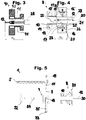
Fig. 2 , - Fig. 5
- einen Schnitt durch ein Tüllenbestückungsmodul zu Beginn eines Bestückungsvorgangs,
- Fig. 6
- das Tüllenbestückungsmodul aus
Fig. 5 , jedoch nachdem der Dorn einer Transfereinheit in eine Übergabestellung geschwenkt wurde, - Fig. 7
- das Tüllenbestückungsmodul mit der offenen, zur Transfereinheit hin gefahrenen Bestückungseinheit,
- Fig. 8
- das Tüllenbestückungmodul mit der nun geschlossenen Bestückungseinheit,
- Fig. 9
- das Tüllenbestückungsmodul mit der geschlossenen Bestückungseinheit nach Ausfahren des Dorns,
- Fig. 10
- das Tüllenbestückungsmodul mit der geschlossenen Bestückungseinheit nach Einfahren einer Spreizhülse in eine Tüllenaufnahmeeinrichtung der Bestückungseinheit,
- Fig. 11
- das Tüllenbestückungsmodul nach einem weiteren Arbeitsschritt, bei dem die Bestückungseinheit von der Transfereinheit weggefahren wurde und nach Einführen des Kabels in die Bestückungseinheit,
- Fig. 12
- das Tüllenbestückungsmodul mit der Bestückungseinheit nach Herausfahren der Spreizhülse aus der Tüllenaufnahmeeinrichtung,
- Fig. 13
- das Tüllenbestückungsmodul nach Beendigung des Bestückungsvorgangs,
- Fig. 14
- einen Querschnitt durch die Tüllenaufnahmeeinrichtung der Bestückungseinheit in einer Teilansicht.
- Fig. 1
- 2 shows a perspective illustration of an overall view of a spout station according to the invention,
- Fig. 2
- a nozzle assembly module of the nozzle station (detailed view from
Fig. 1 ), - Fig. 3
- 2 shows a longitudinal section through an assembly unit of a sleeve assembly module according to the prior art,
- Fig. 4
- a longitudinal section through an assembly unit of the nozzle assembly module according to
Fig. 2 , - Fig. 5
- a section through a nozzle assembly module at the beginning of an assembly process,
- Fig. 6
- the nozzle assembly module
Fig. 5 , but after the mandrel of a transfer unit has been pivoted into a transfer position, - Fig. 7
- the sleeve assembly module with the open assembly unit moved to the transfer unit,
- Fig. 8
- the sleeve assembly module with the now closed assembly unit,
- Fig. 9
- the sleeve assembly module with the closed assembly unit after the mandrel has been extended,
- Fig. 10
- the sleeve assembly module with the closed assembly unit after insertion of an expansion sleeve into a sleeve receiving device of the assembly unit,
- Fig. 11
- the sleeve assembly module after a further work step in which the assembly unit has been moved away from the transfer unit and after the cable has been inserted into the assembly unit,
- Fig. 12
- the sleeve assembly module with the assembly unit after the expansion sleeve has been moved out of the sleeve receiving device,
- Fig. 13
- the sleeve assembly module after the assembly process has ended,
- Fig. 14
- a cross-section through the grommet receiving device of the assembly unit in a partial view.
Die Tüllenstation 1 enthält einen Tüllenspeicher 2 und ein Tüllenbestückungsmodul 3 zum Bestücken eines abisolierten Kabelendes eines Kabels 12 mit einer Tülle auf. Das Tüllenbestückungsmodul 3 umfasst eine sich entlang einer Längsmittelachse 30 verlaufenden Bestückungseinheit 8, mit der eine Tülle auf das Kabel 12, das ebenfalls entlang der Längsmittelachse 30 liegt, gebracht werden . Eine solche Tüllenstation 1 kann als isolierte Maschine verwendet werden oder Bestandteil einer Anlage zum Konfektionieren von Kabeln sein, welche neben der Tüllenstation weiter Abisolierstationen, Crimpstationen und gegebenenfalls Gehäusebestückungsstationen aufweisen kann.The grommet station 1 contains a
Das Kabel 12 wird mit einem (nicht dargestellten) Greifer zum Tüllenbestückungsmodul 3 herangeführt. Eine derartige Tüllenstation 1 entspricht einer vollautomatischen Ausführung. Selbstverständlich wäre es aber auch vorstellbar, anstelle eines Vollautomaten die Tüllenstation 1 mit dem nachfolgend im Detail beschriebenen neuartigen Tüllenbestückungsmodul 3 in einer halbautomatischen Variante oder in anderen Varianten auszuführen.The
Der Tüllenspeicher 2 der Tüllenstation 1 weist eine Trommel 4 zur losen Bevorratung einer Vielzahl von Tüllen auf, eine in die drehende Trommel 4 ragende Förderschiene 5 zur lagerichtigen Speicherung und Weiterbeförderung der Tüllen und eine Vereinzelungseinheit 6 mit einer Ausstossvorrichtung, mittels der jeweils die erste Tülle in der Förderschiene 5 dem Tüllenbestückungsmodul 3 zugeführt wird. Betreffend Tüllenspeicher 2 entspricht die in
Konstruktive Details des Tüllenbestückungsmoduls 3 der Tüllenstation 1 sind aus
Die Transfereinheit 7 weist einen Dornträger 18 auf, der über einem Schwenkmechanismus mit einem motorisch betreibbaren Schwenkmechanismus mit dem Maschinengestell 31 verbunden ist. In der Übernahmestellung, in der der Dorn 9 vertikal ausgerichtet ist, kann mittels der Vereinzelungseinheit 6 eine Tülle 11 auf den Dorn 9 aufgebracht werden. Dies erfolgt mittels eines vertikal auf und ab bewegbaren Stössel einer Ausstossvorrichtung 19 der Vereinzelungseinheit 6. Der Dorn 9 weist ähnlich wie die an sich schon bekannten Dorne aus
Der Dorn 9 ist im Dornträger 18 in axialer Richtung verschiebbar gelagert aufgenommen und kann mittels eines Aktuators in axialer Richtung von einer Ruhestellung in eine ausgefahrene Stellung verschoben werden. Der Dorn 9 ist in der vertikalen Übernahmestellung der Transfereinheit 7 in der Ruhestellung. Der Dorn 9 wird mittels einer Schraubendruckfeder 27 zum Erzeugen einer Vorspannkraft in der Ruhestellung gehalten. Der Dorn 9 ist durch den Dornträger 18 geführt und überragt den Dornträger 18 beidseitig, wobei ein den Dornträger 18 vorderseitig überragender Teil des Dorns die Spitze des Dorns umfasst und zum Handhaben der Tülle dient und wobei ein in Bezug auf den Dornträger 18 rückseitiger Bereich des Dorns einen Bolzen 35 bildet, der von einem linear verfahrbaren Schieber 32 beaufschlagbar ist. Am Ende des Bolzens 35, entlang dem die Feder 27 geführt ist, ist ein Andockelement 33 vorgesehen, das, wenn die Transfereinheit 7 in die horizontale Übergabestellung geschwenkt wird, in eine komplementäre Aufnahme 34 am Schieber 32 eingreift. Nach diesem Eingriff ist die Verschiebebewegung in die ausgefahrene Stellung des Dorns 9 möglich.The
Die Bestückungseinheit 8 besteht im Wesentlichen aus einer sich entlang der Längsmittelachse 30 erstreckenden Spreizhülse 10 zum Halten der Tülle 11 in aufgeweiteten Zustand und zum Platzieren der Tülle 11 auf das Kabelende des Kabels 12 und einer Tüllenaufnahmeeinrichtung 20 zum Aufnehmen und Halten der Tülle 11 während des Bestückungsvorgangs. Die Spreizhülse 10 ist ersichtlicherweise zweiteilig ausgebildet und weist zwei Schalenteile 13, 13' auf. Die Tüllenaufnahmeeinrichtung 20 ist ebenfalls zweiteilig ausgebildet und weist zwei Backen 16, 16' auf. Die gegenläufig radial bewegbaren Backen 16, 16' und die Schalenteilen 13, 13' können paarweise zwischen einer Schliessstellung und einer Offenstellung bewegt werden. In der in
In der Tüllenaufnahmeeinrichtung 20 sind sodann Aufschiebemittel zum weiteren Aufschieben der bereits auf den Dorn 9 aufgeschobenen Tülle 11 auf einen erweiterten Abschnitt des Dorns 9 mit einem grösseren Durchmesser zum Aufweiten der Tülle integriert. Die angesprochenen Aufschiebemittel umfassen in den Backen 16, 16' senkrecht zur Längsmittelachse 20 verschiebbare Aufschiebeelemente 25, 25' (vgl. insb. nachfolgende
Weitere Details zur Ausgestaltung der Bestückungseinheit 8 des Tüllenbestückungsmoduls 3 der Tüllenstation 1 sind aus
Die Spreizhülse 10 umfasst einen länglichen, in geschlossener Stellung zylindrischen Abschnitt mit einer Hülsenspitze 15, auf welchen die Tülle 11 aufschiebbar ist und einen an diesen Abschnitt anschliessenden Flanschabschnitt 14. Die Hülsenspitze 15 ist dabei nach vorne gerichtet, der Flanschabschnitt 14 bildet das hintere Ende der Spreizhülse 10. Der (hier nicht dargestellte) Dorn 9 weist eine Dornspitze auf, die in der Übergabestellung nach vorne bzw. zur Vorderseite hin zeigt. Der Dorn 9 und die den Dorn in der Übergabestellung temporär umgebende Spreizhülse 10 sind somit gleichgerichtet orientiert. Dank der speziellen Anordnung, Ausrichtung und Positionierung von Dorn 9 und Spreizhülse 10 wird auf vorteilhafte Weise gewährleistet, dass die Tülle 11 von der Spreizhülse 10 von hinten her erfassen kann.The
In
In den
Das Verfahren zum Bestücken des Kabels 12 mit einer Tülle 11 ist wie folgt: Wenn der Dorn 9 in der vertikalen Übernahmestellung ist, kann mittels des Stössels der Ausstossvorrichtung 19 eine Tülle 11 auf den Dorn 9 aufgeschoben werden. Nach dem Aufschieben befindet sich die Tülle 11 auf dem in
Die vorliegende Tüllenstation 1 betrifft ein Ausführungsbeispiel, bei der der Transfereinheit 7 genau ein Dorn 9 zugeordnet ist. Es wäre aber auch denkbar, eine Transfereinheit mit vier Dornen vorzusehen. Für diesen Fall müsste der Fachmann das vorgängig beschriebene Tüllenbestückungsmodul 3 derart modifizieren, dass er den Schieber und den axial verschieblichen Dorn weglässt. Die Bestückungeinheit müsste eine weitere Position anfahren können, um die Tülle auf den grösseren Domdurchmesser zu schieben.The present grommet station 1 relates to an embodiment in which exactly one
Weiterhin wäre eine Variante mit einer Tüllenaufnahmeeinrichtung ohne integrierte Aufschiebemittel denkbar. Die Aufschiebemittel könnten ählich wie bei den bekannten Tüllenstationen in der Art der
Die Bestückungseinheit 8 der vorliegenden Tüllenstation 1 wird hauptsächlich zur Bestückung zum Kabel hingeführt. Es wäre aber auch denkbar, die Bestückungseinheit insgesamt feststehend auszugestalten und die notwendigen Bewegungen des Kabels zum Zuführen durch den Kabelgreifer oder einer anderen Kabelfördereinrichtung vorzunehmen.The
Claims (15)
Priority Applications (5)
| Application Number | Priority Date | Filing Date | Title |
|---|---|---|---|
| RS20220284A RS63045B1 (en) | 2018-11-06 | 2018-11-06 | Grommet station |
| EP18204666.4A EP3651288B1 (en) | 2018-11-06 | 2018-11-06 | Grommet station |
| JP2019192481A JP2020078238A (en) | 2018-11-06 | 2019-10-23 | Grommet station |
| US16/662,082 US11482823B2 (en) | 2018-11-06 | 2019-10-24 | Grommet station |
| CN201911059145.8A CN111146661B (en) | 2018-11-06 | 2019-10-31 | Collar station |
Applications Claiming Priority (1)
| Application Number | Priority Date | Filing Date | Title |
|---|---|---|---|
| EP18204666.4A EP3651288B1 (en) | 2018-11-06 | 2018-11-06 | Grommet station |
Publications (2)
| Publication Number | Publication Date |
|---|---|
| EP3651288A1 true EP3651288A1 (en) | 2020-05-13 |
| EP3651288B1 EP3651288B1 (en) | 2022-01-05 |
Family
ID=64267547
Family Applications (1)
| Application Number | Title | Priority Date | Filing Date |
|---|---|---|---|
| EP18204666.4A Active EP3651288B1 (en) | 2018-11-06 | 2018-11-06 | Grommet station |
Country Status (5)
| Country | Link |
|---|---|
| US (1) | US11482823B2 (en) |
| EP (1) | EP3651288B1 (en) |
| JP (1) | JP2020078238A (en) |
| CN (1) | CN111146661B (en) |
| RS (1) | RS63045B1 (en) |
Cited By (1)
| Publication number | Priority date | Publication date | Assignee | Title |
|---|---|---|---|---|
| WO2023232217A1 (en) | 2022-06-02 | 2023-12-07 | Komax Holding Ag | Grommet station |
Families Citing this family (1)
| Publication number | Priority date | Publication date | Assignee | Title |
|---|---|---|---|---|
| CN113871910A (en) * | 2020-06-30 | 2021-12-31 | 泰科电子(上海)有限公司 | Pushing device, wire processing equipment and wire processing method |
Citations (5)
| Publication number | Priority date | Publication date | Assignee | Title |
|---|---|---|---|---|
| EP0410416A2 (en) * | 1989-07-27 | 1991-01-30 | The Whitaker Corporation | Applying a bung seal to an electrical lead |
| EP0534106A1 (en) | 1991-09-25 | 1993-03-31 | Komax Holding Ag | Device for applying grommets to electrical cables |
| EP0626738A1 (en) | 1993-05-06 | 1994-11-30 | Komax Holding Ag | Device for applying crommets to electrical cables |
| US20010039707A1 (en) * | 2000-03-28 | 2001-11-15 | Yoshimi Masuda | Rubber plug fitting apparatus |
| US20020133945A1 (en) * | 2000-02-23 | 2002-09-26 | Yoshiaki Nomoto | Rubber plug insertion apparatus and rubber plug insertion method |
Family Cites Families (4)
| Publication number | Priority date | Publication date | Assignee | Title |
|---|---|---|---|---|
| CN2268263Y (en) * | 1996-11-01 | 1997-11-19 | 陈大宁 | Optical cable, cable connecting box |
| EP1689049B1 (en) | 2005-02-07 | 2008-11-12 | komax Holding AG | Device for applying grommets to electrical cables |
| EP1912296B1 (en) | 2006-10-09 | 2011-06-08 | Komax Holding AG | Device and method for determining the position of a cable mounting on a cable |
| WO2017129658A1 (en) * | 2016-01-26 | 2017-08-03 | Komax Holding Ag | Cable processing device |
-
2018
- 2018-11-06 EP EP18204666.4A patent/EP3651288B1/en active Active
- 2018-11-06 RS RS20220284A patent/RS63045B1/en unknown
-
2019
- 2019-10-23 JP JP2019192481A patent/JP2020078238A/en active Pending
- 2019-10-24 US US16/662,082 patent/US11482823B2/en active Active
- 2019-10-31 CN CN201911059145.8A patent/CN111146661B/en active Active
Patent Citations (5)
| Publication number | Priority date | Publication date | Assignee | Title |
|---|---|---|---|---|
| EP0410416A2 (en) * | 1989-07-27 | 1991-01-30 | The Whitaker Corporation | Applying a bung seal to an electrical lead |
| EP0534106A1 (en) | 1991-09-25 | 1993-03-31 | Komax Holding Ag | Device for applying grommets to electrical cables |
| EP0626738A1 (en) | 1993-05-06 | 1994-11-30 | Komax Holding Ag | Device for applying crommets to electrical cables |
| US20020133945A1 (en) * | 2000-02-23 | 2002-09-26 | Yoshiaki Nomoto | Rubber plug insertion apparatus and rubber plug insertion method |
| US20010039707A1 (en) * | 2000-03-28 | 2001-11-15 | Yoshimi Masuda | Rubber plug fitting apparatus |
Cited By (1)
| Publication number | Priority date | Publication date | Assignee | Title |
|---|---|---|---|---|
| WO2023232217A1 (en) | 2022-06-02 | 2023-12-07 | Komax Holding Ag | Grommet station |
Also Published As
| Publication number | Publication date |
|---|---|
| EP3651288B1 (en) | 2022-01-05 |
| US20200144779A1 (en) | 2020-05-07 |
| CN111146661A (en) | 2020-05-12 |
| JP2020078238A (en) | 2020-05-21 |
| US11482823B2 (en) | 2022-10-25 |
| RS63045B1 (en) | 2022-04-29 |
| CN111146661B (en) | 2023-06-27 |
Similar Documents
| Publication | Publication Date | Title |
|---|---|---|
| EP2320527B1 (en) | Machine for mounting grommets | |
| DE2508578A1 (en) | METHOD AND EQUIPMENT FOR PROCESSING ELECTRIC WIRING | |
| EP2797182B1 (en) | Cable conversion device for cutting, stripping and converting a cable with crimp contacts | |
| CH689272A5 (en) | Device for fitting sleeves of electric cables. | |
| EP3422494B1 (en) | Disconnecting device and method for disconnecting a cable sleeve from a cable | |
| EP3651288B1 (en) | Grommet station | |
| EP1022821B1 (en) | Apparatus and method for assembling a grommet to a lead | |
| CH712088B1 (en) | Method for attaching a component to the end of a stripped cable. | |
| CH681339A5 (en) | ||
| EP0462923B1 (en) | Device for applying soft-elastic grommets on electric cable ends | |
| EP2428452B1 (en) | Method and strapping device for applying flat straps around packages | |
| EP2372848B1 (en) | Device and method for equipping cables with grommets | |
| EP3155700B1 (en) | Method and device for assembling a connector housing | |
| EP3827479B1 (en) | System and method for automatically produce conductors | |
| DE19911729B4 (en) | Method and device for producing a two-chamber tube | |
| EP3652817B1 (en) | Wire handling device | |
| EP2779327B1 (en) | Cable rotating pincer and method of guiding an electrical conductor | |
| EP0924799A2 (en) | Apparatus for wiring connection places of components of electrical devices or installations | |
| DE102017102618B4 (en) | feeding device | |
| DD297288A5 (en) | DEVICE FOR MACHINE APPLYING SEAL STOP TO ELECTRICAL CONDUCTORS | |
| CH689288A5 (en) | Method and apparatus for loading Steckergehaeusen. | |
| CH695096A5 (en) | Automatic machine system is used to insert electrical cables into an elastomer sealing sleeve | |
| DE19540258C2 (en) | Method and device for mounting soft elastic sealing grommets on electrical cable ends | |
| WO2020115535A1 (en) | Cable processing machine, device and method for expanding a sleeve | |
| DE10212993A1 (en) | Electrical cable shoe crimping method has cable filaments held together by insulation ring during crimping procedure |
Legal Events
| Date | Code | Title | Description |
|---|---|---|---|
| PUAI | Public reference made under article 153(3) epc to a published international application that has entered the european phase |
Free format text: ORIGINAL CODE: 0009012 |
|
| STAA | Information on the status of an ep patent application or granted ep patent |
Free format text: STATUS: THE APPLICATION HAS BEEN PUBLISHED |
|
| AK | Designated contracting states |
Kind code of ref document: A1 Designated state(s): AL AT BE BG CH CY CZ DE DK EE ES FI FR GB GR HR HU IE IS IT LI LT LU LV MC MK MT NL NO PL PT RO RS SE SI SK SM TR |
|
| AX | Request for extension of the european patent |
Extension state: BA ME |
|
| STAA | Information on the status of an ep patent application or granted ep patent |
Free format text: STATUS: REQUEST FOR EXAMINATION WAS MADE |
|
| 17P | Request for examination filed |
Effective date: 20201112 |
|
| RAV | Requested validation state of the european patent: fee paid |
Extension state: MA Effective date: 20201112 Extension state: TN Effective date: 20201112 |
|
| RBV | Designated contracting states (corrected) |
Designated state(s): AL AT BE BG CH CY CZ DE DK EE ES FI FR GB GR HR HU IE IS IT LI LT LU LV MC MK MT NL NO PL PT RO RS SE SI SK SM TR |
|
| GRAP | Despatch of communication of intention to grant a patent |
Free format text: ORIGINAL CODE: EPIDOSNIGR1 |
|
| STAA | Information on the status of an ep patent application or granted ep patent |
Free format text: STATUS: GRANT OF PATENT IS INTENDED |
|
| RIC1 | Information provided on ipc code assigned before grant |
Ipc: H01R 43/00 20060101AFI20210629BHEP Ipc: H02G 1/14 20060101ALI20210629BHEP Ipc: H01R 43/28 20060101ALI20210629BHEP |
|
| INTG | Intention to grant announced |
Effective date: 20210713 |
|
| GRAS | Grant fee paid |
Free format text: ORIGINAL CODE: EPIDOSNIGR3 |
|
| GRAA | (expected) grant |
Free format text: ORIGINAL CODE: 0009210 |
|
| STAA | Information on the status of an ep patent application or granted ep patent |
Free format text: STATUS: THE PATENT HAS BEEN GRANTED |
|
| AK | Designated contracting states |
Kind code of ref document: B1 Designated state(s): AL AT BE BG CH CY CZ DE DK EE ES FI FR GB GR HR HU IE IS IT LI LT LU LV MC MK MT NL NO PL PT RO RS SE SI SK SM TR |
|
| REG | Reference to a national code |
Ref country code: GB Ref legal event code: FG4D Free format text: NOT ENGLISH |
|
| REG | Reference to a national code |
Ref country code: CH Ref legal event code: EP |
|
| REG | Reference to a national code |
Ref country code: AT Ref legal event code: REF Ref document number: 1461419 Country of ref document: AT Kind code of ref document: T Effective date: 20220115 |
|
| REG | Reference to a national code |
Ref country code: DE Ref legal event code: R096 Ref document number: 502018008391 Country of ref document: DE |
|
| REG | Reference to a national code |
Ref country code: IE Ref legal event code: FG4D Free format text: LANGUAGE OF EP DOCUMENT: GERMAN |
|
| REG | Reference to a national code |
Ref country code: RO Ref legal event code: EPE |
|
| REG | Reference to a national code |
Ref country code: MA Ref legal event code: VAGR Ref document number: 51804 Country of ref document: MA Kind code of ref document: B1 |
|
| REG | Reference to a national code |
Ref country code: LT Ref legal event code: MG9D |
|
| REG | Reference to a national code |
Ref country code: NL Ref legal event code: MP Effective date: 20220105 |
|
| PG25 | Lapsed in a contracting state [announced via postgrant information from national office to epo] |
Ref country code: NL Free format text: LAPSE BECAUSE OF FAILURE TO SUBMIT A TRANSLATION OF THE DESCRIPTION OR TO PAY THE FEE WITHIN THE PRESCRIBED TIME-LIMIT Effective date: 20220105 |
|
| PG25 | Lapsed in a contracting state [announced via postgrant information from national office to epo] |
Ref country code: SE Free format text: LAPSE BECAUSE OF FAILURE TO SUBMIT A TRANSLATION OF THE DESCRIPTION OR TO PAY THE FEE WITHIN THE PRESCRIBED TIME-LIMIT Effective date: 20220105 Ref country code: PT Free format text: LAPSE BECAUSE OF FAILURE TO SUBMIT A TRANSLATION OF THE DESCRIPTION OR TO PAY THE FEE WITHIN THE PRESCRIBED TIME-LIMIT Effective date: 20220505 Ref country code: NO Free format text: LAPSE BECAUSE OF FAILURE TO SUBMIT A TRANSLATION OF THE DESCRIPTION OR TO PAY THE FEE WITHIN THE PRESCRIBED TIME-LIMIT Effective date: 20220405 Ref country code: LT Free format text: LAPSE BECAUSE OF FAILURE TO SUBMIT A TRANSLATION OF THE DESCRIPTION OR TO PAY THE FEE WITHIN THE PRESCRIBED TIME-LIMIT Effective date: 20220105 Ref country code: HR Free format text: LAPSE BECAUSE OF FAILURE TO SUBMIT A TRANSLATION OF THE DESCRIPTION OR TO PAY THE FEE WITHIN THE PRESCRIBED TIME-LIMIT Effective date: 20220105 Ref country code: ES Free format text: LAPSE BECAUSE OF FAILURE TO SUBMIT A TRANSLATION OF THE DESCRIPTION OR TO PAY THE FEE WITHIN THE PRESCRIBED TIME-LIMIT Effective date: 20220105 Ref country code: BG Free format text: LAPSE BECAUSE OF FAILURE TO SUBMIT A TRANSLATION OF THE DESCRIPTION OR TO PAY THE FEE WITHIN THE PRESCRIBED TIME-LIMIT Effective date: 20220405 |
|
| PG25 | Lapsed in a contracting state [announced via postgrant information from national office to epo] |
Ref country code: PL Free format text: LAPSE BECAUSE OF FAILURE TO SUBMIT A TRANSLATION OF THE DESCRIPTION OR TO PAY THE FEE WITHIN THE PRESCRIBED TIME-LIMIT Effective date: 20220105 Ref country code: LV Free format text: LAPSE BECAUSE OF FAILURE TO SUBMIT A TRANSLATION OF THE DESCRIPTION OR TO PAY THE FEE WITHIN THE PRESCRIBED TIME-LIMIT Effective date: 20220105 Ref country code: GR Free format text: LAPSE BECAUSE OF FAILURE TO SUBMIT A TRANSLATION OF THE DESCRIPTION OR TO PAY THE FEE WITHIN THE PRESCRIBED TIME-LIMIT Effective date: 20220406 Ref country code: FI Free format text: LAPSE BECAUSE OF FAILURE TO SUBMIT A TRANSLATION OF THE DESCRIPTION OR TO PAY THE FEE WITHIN THE PRESCRIBED TIME-LIMIT Effective date: 20220105 |
|
| PG25 | Lapsed in a contracting state [announced via postgrant information from national office to epo] |
Ref country code: IS Free format text: LAPSE BECAUSE OF FAILURE TO SUBMIT A TRANSLATION OF THE DESCRIPTION OR TO PAY THE FEE WITHIN THE PRESCRIBED TIME-LIMIT Effective date: 20220505 |
|
| REG | Reference to a national code |
Ref country code: DE Ref legal event code: R097 Ref document number: 502018008391 Country of ref document: DE |
|
| PG25 | Lapsed in a contracting state [announced via postgrant information from national office to epo] |
Ref country code: SM Free format text: LAPSE BECAUSE OF FAILURE TO SUBMIT A TRANSLATION OF THE DESCRIPTION OR TO PAY THE FEE WITHIN THE PRESCRIBED TIME-LIMIT Effective date: 20220105 Ref country code: SK Free format text: LAPSE BECAUSE OF FAILURE TO SUBMIT A TRANSLATION OF THE DESCRIPTION OR TO PAY THE FEE WITHIN THE PRESCRIBED TIME-LIMIT Effective date: 20220105 Ref country code: EE Free format text: LAPSE BECAUSE OF FAILURE TO SUBMIT A TRANSLATION OF THE DESCRIPTION OR TO PAY THE FEE WITHIN THE PRESCRIBED TIME-LIMIT Effective date: 20220105 Ref country code: DK Free format text: LAPSE BECAUSE OF FAILURE TO SUBMIT A TRANSLATION OF THE DESCRIPTION OR TO PAY THE FEE WITHIN THE PRESCRIBED TIME-LIMIT Effective date: 20220105 Ref country code: CZ Free format text: LAPSE BECAUSE OF FAILURE TO SUBMIT A TRANSLATION OF THE DESCRIPTION OR TO PAY THE FEE WITHIN THE PRESCRIBED TIME-LIMIT Effective date: 20220105 |
|
| PLBE | No opposition filed within time limit |
Free format text: ORIGINAL CODE: 0009261 |
|
| STAA | Information on the status of an ep patent application or granted ep patent |
Free format text: STATUS: NO OPPOSITION FILED WITHIN TIME LIMIT |
|
| PG25 | Lapsed in a contracting state [announced via postgrant information from national office to epo] |
Ref country code: AL Free format text: LAPSE BECAUSE OF FAILURE TO SUBMIT A TRANSLATION OF THE DESCRIPTION OR TO PAY THE FEE WITHIN THE PRESCRIBED TIME-LIMIT Effective date: 20220105 |
|
| 26N | No opposition filed |
Effective date: 20221006 |
|
| PG25 | Lapsed in a contracting state [announced via postgrant information from national office to epo] |
Ref country code: SI Free format text: LAPSE BECAUSE OF FAILURE TO SUBMIT A TRANSLATION OF THE DESCRIPTION OR TO PAY THE FEE WITHIN THE PRESCRIBED TIME-LIMIT Effective date: 20220105 |
|
| PG25 | Lapsed in a contracting state [announced via postgrant information from national office to epo] |
Ref country code: MC Free format text: LAPSE BECAUSE OF FAILURE TO SUBMIT A TRANSLATION OF THE DESCRIPTION OR TO PAY THE FEE WITHIN THE PRESCRIBED TIME-LIMIT Effective date: 20220105 |
|
| GBPC | Gb: european patent ceased through non-payment of renewal fee |
Effective date: 20221106 |
|
| REG | Reference to a national code |
Ref country code: BE Ref legal event code: MM Effective date: 20221130 |
|
| PG25 | Lapsed in a contracting state [announced via postgrant information from national office to epo] |
Ref country code: LU Free format text: LAPSE BECAUSE OF NON-PAYMENT OF DUE FEES Effective date: 20221106 |
|
| PG25 | Lapsed in a contracting state [announced via postgrant information from national office to epo] |
Ref country code: IE Free format text: LAPSE BECAUSE OF NON-PAYMENT OF DUE FEES Effective date: 20221106 Ref country code: GB Free format text: LAPSE BECAUSE OF NON-PAYMENT OF DUE FEES Effective date: 20221106 |
|
| PG25 | Lapsed in a contracting state [announced via postgrant information from national office to epo] |
Ref country code: FR Free format text: LAPSE BECAUSE OF NON-PAYMENT OF DUE FEES Effective date: 20221130 Ref country code: BE Free format text: LAPSE BECAUSE OF NON-PAYMENT OF DUE FEES Effective date: 20221130 |
|
| PGFP | Annual fee paid to national office [announced via postgrant information from national office to epo] |
Ref country code: RS Payment date: 20231024 Year of fee payment: 6 Ref country code: RO Payment date: 20231103 Year of fee payment: 6 Ref country code: IT Payment date: 20231124 Year of fee payment: 6 Ref country code: DE Payment date: 20231127 Year of fee payment: 6 Ref country code: CH Payment date: 20231202 Year of fee payment: 6 |
|
| PG25 | Lapsed in a contracting state [announced via postgrant information from national office to epo] |
Ref country code: HU Free format text: LAPSE BECAUSE OF FAILURE TO SUBMIT A TRANSLATION OF THE DESCRIPTION OR TO PAY THE FEE WITHIN THE PRESCRIBED TIME-LIMIT; INVALID AB INITIO Effective date: 20181106 |