EP3650602A1 - Asphalt paver - Google Patents
Asphalt paver Download PDFInfo
- Publication number
- EP3650602A1 EP3650602A1 EP18827620.8A EP18827620A EP3650602A1 EP 3650602 A1 EP3650602 A1 EP 3650602A1 EP 18827620 A EP18827620 A EP 18827620A EP 3650602 A1 EP3650602 A1 EP 3650602A1
- Authority
- EP
- European Patent Office
- Prior art keywords
- lighting apparatus
- controller
- asphalt finisher
- lighting
- tractor
- Prior art date
- Legal status (The legal status is an assumption and is not a legal conclusion. Google has not performed a legal analysis and makes no representation as to the accuracy of the status listed.)
- Pending
Links
- 239000010426 asphalt Substances 0.000 title claims abstract description 70
- 238000005286 illumination Methods 0.000 claims abstract description 73
- 239000000463 material Substances 0.000 claims abstract description 23
- 230000005540 biological transmission Effects 0.000 claims description 12
- 230000004044 response Effects 0.000 claims description 7
- 238000001514 detection method Methods 0.000 claims description 2
- 230000007246 mechanism Effects 0.000 description 24
- 230000003287 optical effect Effects 0.000 description 18
- 238000004891 communication Methods 0.000 description 16
- 230000008859 change Effects 0.000 description 8
- 230000006870 function Effects 0.000 description 8
- 238000000034 method Methods 0.000 description 8
- 230000008569 process Effects 0.000 description 8
- 238000010586 diagram Methods 0.000 description 3
- 230000007423 decrease Effects 0.000 description 2
- 239000003550 marker Substances 0.000 description 2
- 230000007480 spreading Effects 0.000 description 2
- 230000001133 acceleration Effects 0.000 description 1
- 230000004075 alteration Effects 0.000 description 1
- 230000008901 benefit Effects 0.000 description 1
- 238000005056 compaction Methods 0.000 description 1
- 230000004313 glare Effects 0.000 description 1
- 239000010720 hydraulic oil Substances 0.000 description 1
- 230000004048 modification Effects 0.000 description 1
- 238000012986 modification Methods 0.000 description 1
- 238000003825 pressing Methods 0.000 description 1
Images


Classifications
-
- H—ELECTRICITY
- H05—ELECTRIC TECHNIQUES NOT OTHERWISE PROVIDED FOR
- H05B—ELECTRIC HEATING; ELECTRIC LIGHT SOURCES NOT OTHERWISE PROVIDED FOR; CIRCUIT ARRANGEMENTS FOR ELECTRIC LIGHT SOURCES, IN GENERAL
- H05B47/00—Circuit arrangements for operating light sources in general, i.e. where the type of light source is not relevant
- H05B47/10—Controlling the light source
- H05B47/165—Controlling the light source following a pre-assigned programmed sequence; Logic control [LC]
-
- B—PERFORMING OPERATIONS; TRANSPORTING
- B60—VEHICLES IN GENERAL
- B60Q—ARRANGEMENT OF SIGNALLING OR LIGHTING DEVICES, THE MOUNTING OR SUPPORTING THEREOF OR CIRCUITS THEREFOR, FOR VEHICLES IN GENERAL
- B60Q1/00—Arrangement of optical signalling or lighting devices, the mounting or supporting thereof or circuits therefor
- B60Q1/02—Arrangement of optical signalling or lighting devices, the mounting or supporting thereof or circuits therefor the devices being primarily intended to illuminate the way ahead or to illuminate other areas of way or environments
- B60Q1/24—Arrangement of optical signalling or lighting devices, the mounting or supporting thereof or circuits therefor the devices being primarily intended to illuminate the way ahead or to illuminate other areas of way or environments for lighting other areas than only the way ahead
- B60Q1/249—Arrangement of optical signalling or lighting devices, the mounting or supporting thereof or circuits therefor the devices being primarily intended to illuminate the way ahead or to illuminate other areas of way or environments for lighting other areas than only the way ahead for illuminating the field of view of a sensor or camera
-
- E—FIXED CONSTRUCTIONS
- E01—CONSTRUCTION OF ROADS, RAILWAYS, OR BRIDGES
- E01C—CONSTRUCTION OF, OR SURFACES FOR, ROADS, SPORTS GROUNDS, OR THE LIKE; MACHINES OR AUXILIARY TOOLS FOR CONSTRUCTION OR REPAIR
- E01C19/00—Machines, tools or auxiliary devices for preparing or distributing paving materials, for working the placed materials, or for forming, consolidating, or finishing the paving
- E01C19/48—Machines, tools or auxiliary devices for preparing or distributing paving materials, for working the placed materials, or for forming, consolidating, or finishing the paving for laying-down the materials and consolidating them, or finishing the surface, e.g. slip forms therefor, forming kerbs or gutters in a continuous operation in situ
-
- F—MECHANICAL ENGINEERING; LIGHTING; HEATING; WEAPONS; BLASTING
- F21—LIGHTING
- F21S—NON-PORTABLE LIGHTING DEVICES; SYSTEMS THEREOF; VEHICLE LIGHTING DEVICES SPECIALLY ADAPTED FOR VEHICLE EXTERIORS
- F21S41/00—Illuminating devices specially adapted for vehicle exteriors, e.g. headlamps
- F21S41/60—Illuminating devices specially adapted for vehicle exteriors, e.g. headlamps characterised by a variable light distribution
- F21S41/65—Illuminating devices specially adapted for vehicle exteriors, e.g. headlamps characterised by a variable light distribution by acting on light sources
- F21S41/657—Illuminating devices specially adapted for vehicle exteriors, e.g. headlamps characterised by a variable light distribution by acting on light sources by moving light sources
-
- F—MECHANICAL ENGINEERING; LIGHTING; HEATING; WEAPONS; BLASTING
- F21—LIGHTING
- F21V—FUNCTIONAL FEATURES OR DETAILS OF LIGHTING DEVICES OR SYSTEMS THEREOF; STRUCTURAL COMBINATIONS OF LIGHTING DEVICES WITH OTHER ARTICLES, NOT OTHERWISE PROVIDED FOR
- F21V19/00—Fastening of light sources or lamp holders
- F21V19/02—Fastening of light sources or lamp holders with provision for adjustment, e.g. for focusing
-
- F—MECHANICAL ENGINEERING; LIGHTING; HEATING; WEAPONS; BLASTING
- F21—LIGHTING
- F21V—FUNCTIONAL FEATURES OR DETAILS OF LIGHTING DEVICES OR SYSTEMS THEREOF; STRUCTURAL COMBINATIONS OF LIGHTING DEVICES WITH OTHER ARTICLES, NOT OTHERWISE PROVIDED FOR
- F21V23/00—Arrangement of electric circuit elements in or on lighting devices
- F21V23/04—Arrangement of electric circuit elements in or on lighting devices the elements being switches
Definitions
- the disclosures herein relate to an asphalt finisher.
- An asphalt finisher may include a lighting apparatus for use in nighttime operations, a generator for generating power for supply to the lighting apparatus, and a hydraulic motor for driving the generator (see Patent Document 1).
- the lighting apparatus is typically mounted at a predetermined location on the asphalt finisher with a fixed mounting angle.
- Patent Document 1 Japanese Patent Application Publication No. H03-125806
- the lighting apparatus is moved away from workers working behind the asphalt finisher as the asphalt finisher moves away. Areas around the workers may thus be not properly illuminated.
- An asphalt finisher includes a tractor, a hopper disposed in front of the tractor and configured to accept a pavement material, a conveyor configured to supply the pavement material in the hopper to a rear side of the tractor, a screw configured to lay and spread the pavement material supplied by the conveyor at the rear side of the tractor, a screed configured to flatten the pavement material laid and spread by the screw at a rear side of the screw, and a controller configured to adjust an illumination range of a lighting apparatus.
- Fig. 1 is a side-elevation view of an asphalt finisher 100 which is an example of road machinery according to an embodiment of the present invention.
- the road machinery may be a base paver, a tack coat paver, a multi-asphalt paver, or the like.
- Fig. 2 is a top view of the asphalt finisher 100.
- the asphalt finisher 100 is mainly comprised of a tractor 1, a hopper 2, and a screed 3.
- the direction of the hopper 2 as viewed from the tractor 1 (the +X direction) is referred to as a front direction
- the direction of the screed 3 as viewed from the tractor 1 (the -X direction) is referred to as a rear direction.
- the tractor 1 is a mechanism configured to drive the asphalt finisher 100.
- the tractor 1 uses a rear-wheel hydraulic motor to rotate rear wheels 5, and uses a front-wheel hydraulic motor to rotate front wheels 6, thereby causing the asphalt finisher 100 to move.
- the rear-wheel hydraulic motor and the front-wheel hydraulic motor rotates upon receiving hydraulic oil from hydraulic pumps.
- the rear wheels 5 and the front wheels 6 may be replaced with crawlers.
- a controller 50 is a controller configured to control the asphalt finisher 100.
- the controller 50 which is comprised of a microcomputer including a CPU, a memory, a non-volatile storage device, and the like, is mounted on the tractor 1.
- Various functions of the controller 50 are provided by the CPU executing programs stored in a non-volatile storage medium.
- the hopper 2 is a mechanism for accepting pavement material.
- the hopper 2 is installed in front of the tractor 1, and is configured to be opened and closed in the Y axis direction (i.e., width direction) by hopper cylinders.
- the hopper 2 of the asphalt finisher 100 is typically fully opened to accept pavement material (e.g., an asphalt mix) from the bed of a dump truck.
- Fig. 1 and Fig. 2 illustrates the fully opened state of the hopper 2.
- the hopper 2 is closed, so that the paving material disposed near the inner wall of the hopper 2 is collected toward the center of the hopper 2.
- a conveyor CV situated at the center of the hopper 2 can supply the pavement material to the rear side of the tractor 1.
- the pavement material supplied to the rear side of the tractor 1 is laid and spread by a screw SC in the vehicle width direction in rear of the tractor 1 and in front of the screed 3.
- the screw SC has extension screws attached to the left and right thereof.
- a pavement material PV laid and spread by the screw SC is shown as a dot pattern.
- the screed 3 is a mechanism for flatten the pavement material PV.
- the screed 3 includes a front screed 30 and a rear screed 31.
- the screed 3, which is a free floating screed towed by the tractor 1, is coupled to the tractor 1 via a leveling arm 3A.
- a moldboard 43 is attached to the front of the screed 3.
- the moldboard 43 regulates the amount of pavement material PV that stays in front of the screed 3.
- the pavement material PV passes through the gap between the lower end of the moldboard 43 and a roadbed RB to reach under the screed 3.
- a guide rail 1G is provided at the top of the tractor 1 for use as a handrail by an operator of the asphalt finisher 100.
- An object detecting apparatus 51 and a lighting apparatus 52 are mounted on the guide rail 1G.
- the object detecting apparatus 51 and the lighting apparatus 52 may alternatively be mounted on the bottom of the operator seat 1S or at some other location on the tractor 1.
- the object detecting apparatus 51 is configured to detect an object present around the asphalt finisher 100.
- the object detecting apparatus 51 which is a camera capable of capturing a rear view image behind the asphalt finisher 100, is wirelessly connected or wire-connected to the controller 50.
- the controller 50 may perform various image processing on images captured by the object detecting apparatus 51, for example, thereby detecting the positions of workers behind the asphalt finisher 100.
- the workers preferably wear an armband, a helmet, or the like on which a predetermined marker is provided. This is for the purpose of making a recognition task easier for image recognition process.
- the controller 50 may search for the image of the predetermined marker to detect the positions of workers.
- the controller 50 may detect a worker making a predetermined gesture to detect the position of the worker or the position to which light should be directed.
- the object detecting apparatus 51 may alternatively be a stereo camera, a millimeter-wave radar, an ultrasonic sensor, a laser radar, an infrared sensor, a whatsoever, or the like.
- the object detecting apparatus 51 may additionally be configured to detect an object situated in front of or to either side of the asphalt finisher 100.
- one object detecting apparatus 51 is mounted on the asphalt finisher 100.
- a plurality of object detecting apparatuses 51 may be mounted on the asphalt finisher 100.
- the lighting apparatus 52 is configured to illuminate areas around the asphalt finisher 100.
- the lighting apparatus 52 is positioned such as to illuminate areas behind the asphalt finisher 100, and is wirelessly connected or wire-connected to the controller 50.
- the lighting apparatus 52 may be mounted such as to additionally illuminate areas in front of or to either side of the asphalt finisher 100.
- one lighting apparatus 52 is mounted on the asphalt finisher 100.
- a plurality of lighting apparatuses 52 may be mounted on the asphalt finisher 100.
- Fig. 3 is a block diagram illustrating an example of the configuration of the lighting system LS.
- the lighting system LS is mainly comprised of the controller 50, the object detecting apparatus 51, the lighting apparatus 52, an information acquiring apparatus 53, and the like.
- the controller 50, the object detecting apparatus 51, the lighting apparatus 52, and the information acquiring apparatus 53 receive power from a power supply 60.
- the power supply 60 converts AC power, generated by a generator 62 driven by an engine 61, into DC power.
- Thick dashed lines in Fig. 3 represent power lines, and the double line represents a mechanical connection between the engine 61 and the generator 62.
- the controller 50 includes a lighting controller 50a as a functional element.
- the lighting controller 50a which is implemented as software, hardware, or firmware, controls the lighting apparatus 52.
- the lighting controller 50a determines whether lighting is needed based on the output of the object detecting apparatus 51, the information acquiring apparatus 53, and the like.
- the lighting controller 50a determines a target illumination area, and supplies a instruction regarding the target illumination area to the lighting apparatus 52.
- the target illumination area refers to the area that needs to be illuminated by the lighting apparatus 52.
- the lighting apparatus 52 includes an optical axis adjusting mechanism 52a and a zoom mechanism 52b.
- the lighting apparatus 52 drives at least one of the optical axis adjusting mechanism 52a and the zoom mechanism 52b in response to the instruction from the controller 50 to change an illumination range. This is for the purpose of illuminating the target illumination area.
- the lighting apparatus 52 may be configured to change at least one of light intensity (i.e., brightness), wavelengths (i.e., color), and the like.
- the optical axis adjusting mechanism 52a changes the direction of the optical axis of the lighting apparatus 52.
- an electric motor and a gear mechanism are used to mechanically change the orientation of the optical axis of the lighting apparatus 52 in vertical directions and horizontal directions. Namely, the positioning of the light source of the lighting apparatus 52 is changed to modify the direction of the optical axis of the lighting apparatus 52.
- the optical axis adjusting mechanism 52a may change the optical axis of the lighting apparatus 52 by optical means. Namely, the positioning of a mirror or the like may be changed to modify the direction of the optical axis of the lighting apparatus 52.
- the zoom mechanism 52b changes an illumination range provided by the lighting apparatus 52.
- an electric motor and a gear mechanism are used to change the positioning of an optical device in the lighting apparatus 52 to increase or decrease the illumination range provided by the lighting apparatus 52.
- the information acquiring apparatus 53 acquires information, and outputs the acquired information to the controller 50.
- the information acquiring apparatus 53 includes at least one of a travel speed sensor, a steering angle sensor, a pavement width sensor, a brightness sensor (including a camera), and a light switch, for example.
- the travel speed sensor detects the travel speed of the asphalt finisher 100.
- the steering angle sensor detects the steering angle of the asphalt finisher 100.
- the pavement width sensor calculates a pavement width by detecting the extension of the rear screed 31.
- the brightness sensor detects the brightness of areas around the asphalt finisher 100.
- the brightness sensor may be a luminance sensor embedded in the camera of the object detecting apparatus 51. This is because the luminance sensor embedded in the camera of the object detecting apparatus 51 is configured to detect the luminance of an area at least within the view of the camera.
- the light switch may be used by an operator to turn on and off the lighting apparatus 52.
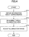
- Fig. 4 is a flowchart illustrating an example of the lighting control process.
- the lighting controller 50a performs the lighting control process at predetermined control intervals during the operation of the lighting apparatus 52.
- the lighting controller 50a starts performing the lighting control process at the time the lighting apparatus 52 is activated by operating the light switch, for example.
- the lighting control process may be started at the time the lighting apparatus 52 automatically starts illuminating in response to the output of the brightness sensor.
- the lighting apparatus 52 illuminates a standard illumination area RO indicated by the dot-and-dash line in Fig. 2 , for example.
- the lighting controller 50a obtains status information about areas around the asphalt finisher 100 (step ST1). For example, the lighting controller 50a determines, based on the output of the object detecting apparatus 51, whether there is a worker in a predetermined area behind the asphalt finisher 100. Upon detecting a worker in the predetermined area, the position of the worker is then identified.
- the lighting controller 50a determines a target illumination area (step ST2). For example, upon determining the presence of a worker WK1 behind the asphalt finisher 100 as shown in Fig. 2 , the lighting controller 50a sets an area of a predetermined size including the position of the worker WK1 as a target illumination area. Namely, an area R1 indicated by the dashed line is set as the target illumination area.
- the worker WK1 is engaged in the task of laying and spreading, with a rake, the joint portion of a new pavement NP adjacent to an existing pavement AP .
- the lighting controller 50a adjusts the illumination range of the lighting apparatus 52 so that the target illumination area is illuminated (Step ST3).
- the illumination range of the lighting apparatus 52 is adjustable based on the detection result of the object detecting apparatus 51.
- the lighting controller 50a outputs an instruction regarding the target illumination area to the lighting apparatus 52.
- the instruction regarding the target illumination area includes information about the direction of the optical axis of the lighting apparatus 52 and information about the size of an illumination range.
- the lighting apparatus 52 activates at least one of the optical axis adjusting mechanism 52a and the zoom mechanism 52b to adjust the illumination range such that the illumination range coincides with the target illumination area or such that the illumination range includes the target illumination area.
- the controller 50 may change the illumination range of the lighting apparatus 52 in response to a change in the relative position of the worker WK1 with respect to the asphalt finisher 100. Namely, the lighting apparatus 52 can continuously illuminate the worker WK1 by tracking the worker WK1.
- the lighting controller 50a may obtain status information about the movement of the asphalt finisher 100 to determine a target illumination area.
- the illumination range of the lighting apparatus 52 may be adjusted in response to the state of movement.
- the target illumination area may be determined based on the output of the pavement width sensor.
- the illumination range of the lighting apparatus 52 is expanded in the vehicle width direction in proportion to the pavement width, for example.
- the target illumination area may be determined based on the output of the travel speed sensor.
- the illumination range of the lighting apparatus 52 is expanded in the vehicle length direction in proportion to the travel speed, for example.
- Fig. 5 is a block diagram illustrating another example of the configuration of the lighting system LS.
- Fig. 6 is a side-elevation view of the asphalt finisher 100 equipped with the lighting system LS of Fig. 5 .
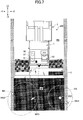
- Fig. 7 is a top view of the asphalt finisher 100 equipped with the lighting system LS of Fig. 5 .
- the lighting system LS of Fig. 5 differs from the lighting system LS of Fig. 3 in that a communication apparatus 57 is provided to control communication with at least one of a transmitter 150 and a flight object 200. Other than this, anything else is the same. In consideration of this, differences will be described in detail while avoiding the description of the same parts.
- the transmitter 150 which is a device carried by a worker, may be a mobile phone, a smartphone, a wearable PC, a general-purpose remote controller, and the like. In the present embodiment, a wristwatch-type transmitter is used.
- the transmitter 150 is comprised of a controller 151, a transmission apparatus 152, a battery 153, and the like.
- the controller 151 and the transmission apparatus 152 receive power from the battery 153.
- the controller 151 is a device for controlling the transmitter 150.
- the controller 151 is comprised of a microcomputer.
- the controller 151 executes programs corresponding to respective functions to provide the functions corresponding to these programs.
- the transmission apparatus 152 transmits information to outside the transmitter 150.
- the transmission apparatus 152 repeatedly transmits information receivable by the asphalt finisher 100 at a predetermined transmission interval, for example.
- the transmission apparatus 152 may alternatively transmit information in response to a predetermined manual operation performed by a worker such as the pressing of a transmission button.
- the transmission apparatus 152 may transmit information when a predetermined transmission condition is satisfied such as the arrival of a predetermined hour.
- the flight object 200 which is an autonomous flight object capable of flying under remote control or autonomous control, and may be a multicopter, an airship, or the like. In the present embodiment, a quadcopter equipped with a lighting apparatus 204 is used.
- the flight object 200 is comprised of a controller 201, a communication apparatus 202, an autonomous flight apparatus 203, a lighting apparatus 204, a battery 205, and the like.
- the controller 201, the communication apparatus 202, the autonomous flight apparatus 203, and the lighting apparatus 204 receive power from the battery 205.
- the controller 201, the communication apparatus 202, the autonomous flight apparatus 203, and the lighting apparatus 204 may alternatively receive power from the power supply 60 mounted on the asphalt finisher 100.
- the flight object 200 is connected to the power supply 60 through a power supply cable.
- the controller 201 is a device for controlling the flight object 200.
- the controller 201 is comprised of a microcomputer.
- the controller 201 executes programs corresponding to respective functions to provide the functions corresponding to these programs.
- the communication apparatus 202 receives information from the outside of the flight object 200
- the communication apparatus 202 receives information transmitted by the asphalt finisher 100, for example.
- the communication apparatus 202 may transmit information to the outside of the flight object 200. In this case, the communication apparatus 202 may transmit information receivable by the asphalt finisher 100, for example.
- the autonomous flight apparatus 203 is a device for achieving autonomous flight of the flight object 200.
- the autonomous flight apparatus 203 includes a flight controller and a electric motor.
- the flight controller includes at least one of various sensors such as a gyro sensor, an acceleration sensor, a geomagnetic sensor (i.e., orientation sensor), a barometric sensor, a positioning sensor, and an ultrasonic sensor, and provides an attitude maintaining function, an altitude maintaining function, and the like.
- the electric motor receives power from the battery 205 to rotate the propellers.
- the autonomous flight apparatus 203 Upon receiving information about a flight path from the controller 201, for example, the autonomous flight apparatus 203 controls the rotational speeds of four propellers separately, thereby causing the flight object 200 to move along the flight path while maintaining the attitude and altitude of the flight object 200.
- the information about a flight path is comprised of the latitude, longitude, and altitude of the flight position, for example.
- the controller 201 acquires information about a flight path from the asphalt finisher 100 through the communication apparatus 202, for example.
- the controller 201 may determine a flight path by taking into account the positions of obstacles that may obstruct the flight of the flight object 200. Obstacles that may obstruct flight may be detected based on images captured by a camera, for example.
- the camera may be the camera mounted on the asphalt finisher 100, or may be a camera mounted on the flight object 200.
- the flight object 200 may autonomously avoid obstacles that may obstruct the flight, based on at least one output of a camera, a sensor, and the like mounted on the flight object 200.
- the lighting apparatus 204 illuminates areas under the flight object 200.
- the lighting apparatus 204 is mounted such as to illuminate areas under the flight object 200, and is coupled to the controller 201.
- one lighting apparatus 204 is mounted on the flight object 200.
- a plurality of lighting apparatuses 204 may be mounted on the flight object 200.
- the lighting apparatus 204 may include an optical axis adjusting mechanism and a zoom mechanism, similarly to the lighting apparatus 52. In this case, the lighting apparatus 204 causes at least one of the optical axis adjusting mechanism and the zoom mechanism to adjust an illumination range in response to an instruction from the controller 201.
- the lighting apparatus 204 may be configured to change at least one of light intensity (i.e., brightness), wavelengths (i.e., color), and the like.
- the flight object 200 may be provided with a camera. In this case, the flight object 200 may recognize the asphalt finisher 100 and workers based on images captured by the camera. Alternatively, the flight object 200 may receive information indicative of positions of the asphalt finisher 100 and workers. With these arrangement, the flight object 200 may fly while being in the possession of information about the relative positions of the asphalt finisher 100 and the workers.
- the communication apparatus 57 is a device mounted on the asphalt finisher 100 and coupled to the controller 50. Communication between the controller 50 and external equipment can thus be controlled.
- the communication apparatus 57 functions as a receiver apparatus to receive signals transmitted by the transmitter 150.
- communication standards such as Bluetooth (registered trademark) or Wi-Fi (registered trademark) may be utilized.
- the controller 50 may obtain information about the position of the transmitter 150, i.e., the position of a worker, based on the output of the transmitter 150 (e.g., radio wave intensity).
- the controller 50 also serves as a transmitter apparatus to transmit information about the illumination range of the lighting apparatus 204 such as a target illumination area to the flight object 200.
- the lighting controller 50a determines, based on the output of the transmitter 150 serving as the object detecting apparatus 51, whether there is a worker in a predetermined area behind the asphalt finisher 100. Upon determining the presence of a worker in the predetermined area, the lighting controller 50a obtains information about the positon of the worker, followed by determining a target illumination area based on this position.
- the lighting controller 50a sets one or more areas of a predetermined size including the positions of the workers WK2 through WK4 as one or more target illumination areas.
- the lighting controller 50a is able to utilize the lighting apparatus 52 and the lighting apparatus 204, and thus sets two target illumination areas. Namely, an area R2 indicated by a dashed line is set as a first target illumination area with respect to the lighting apparatus 52, and an area R3 indicated by a dashed line is set as a second target illumination area with respect to the lighting apparatus 204.
- the worker WK2 is engaged in the task of laying and spreading, with a rake, the joint portion of a new pavement NP adjacent to an existing pavement AP .
- the worker WK3 is engaged in the task of measuring the thickness of the new pavement NP by using a thickness gage.
- the worker WK4 is engaged in the task of providing compaction for the joint portion of the new pavement NP adjacent to the existing pavement AP by use of a compactor.
- the first target illumination area includes the positions of the worker WK2 and the worker WK3.
- the second target illumination area includes the position of the worker WK4.
- the lighting controller 50a may set two target illumination areas such that the first target illumination area includes the position of the worker WK2 and the second target illumination area includes the positions of the worker WK3 and the worker WK4.
- the transmitter 150 may alternatively be attached to at least one of the work tools such as a rake, a thickness gage, and a compactor.
- the lighting controller 50a adjusts the illumination range of the lighting apparatus 52 such that the first target illumination area is illuminated, and adjusts the illumination range of the lighting apparatus 204 such that the second target illumination area is illuminated.
- the lighting controller 50a outputs an instruction regarding the first target illumination area to the lighting apparatus 52.
- the lighting apparatus 52 activates at least one of the optical axis adjusting mechanism 52a and the zoom mechanism 52b to adjust the illumination range such that the illumination range coincides with the first target illumination area or such that the illumination range includes the first target illumination area.
- the lighting controller 50a outputs an instruction regarding the second target illumination area to the lighting apparatus 204 of the flight object 200.
- the lighting apparatus 204 activates at least one of the optical axis adjusting mechanism and the zoom mechanism to adjust the illumination range such that the illumination range coincides with the second target illumination area or such that the illumination range includes the second target illumination area.
- the controller 201 having received the instruction regarding the second target illumination area may cause the flight object 200 to fly such that the illumination area of the lighting apparatus 204 coincides with the second target illumination area or such that the illumination area includes the second target illumination area.
- the flight object 200 may illuminate areas around the worker WK4 with the lighting apparatus 204 while flying over the worker WK4, for example. Since light is shone from a relatively high position, the worker WK4 is not likely to feel too much glare, compared with a balloon light.
- the asphalt finisher 100 is provided with the controller 50 to adjust at least one of the illumination rages of the lighting apparatus 52 and the lighting apparatus 204, thereby more properly illuminating areas around workers.
- the asphalt finisher 100 is configured to utilize the power of the power supply 60 mounted on the tractor 1 to illuminate areas around workers. Because of this, workers are not forced to prepare a lighting apparatus equipped with a generator such as a balloon light, and, yet, areas around the workers can properly be illuminated when lighting is needed in an emergency situation such as when the work time extends past sunset. Further, the areas around the workers can properly be illuminated without relying on a lighting apparatus mounted on separate road machinery such as a road roller which is operated around the asphalt finisher 100. As a result, the efficiency of paving work is improved.
Abstract
Description
- The disclosures herein relate to an asphalt finisher.
- An asphalt finisher, as known in the art, may include a lighting apparatus for use in nighttime operations, a generator for generating power for supply to the lighting apparatus, and a hydraulic motor for driving the generator (see Patent Document 1).
- The lighting apparatus is typically mounted at a predetermined location on the asphalt finisher with a fixed mounting angle.
- [Patent Document 1] Japanese Patent Application Publication No.
H03-125806 - As a downside of being secured to the asphalt finisher, the lighting apparatus is moved away from workers working behind the asphalt finisher as the asphalt finisher moves away. Areas around the workers may thus be not properly illuminated.
- In consideration of the above, it may be desired to provide an asphalt finisher that more properly illuminates areas around workers.
- An asphalt finisher according to an embodiment of the present invention includes a tractor, a hopper disposed in front of the tractor and configured to accept a pavement material, a conveyor configured to supply the pavement material in the hopper to a rear side of the tractor, a screw configured to lay and spread the pavement material supplied by the conveyor at the rear side of the tractor, a screed configured to flatten the pavement material laid and spread by the screw at a rear side of the screw, and a controller configured to adjust an illumination range of a lighting apparatus.
- With the above-noted arrangement, an asphalt finisher that more properly illuminates areas around workers is provided.
-
-
Fig. 1 is a side-elevation view of an asphalt finisher according to an embodiment of the present invention. -
Fig. 2 is a top view of the asphalt finisher ofFig. 1 . -
Fig. 3 is a block diagram illustrating an example of the configuration of a lighting system. -
Fig. 4 is a flowchart of a lighting control process. -
Fig. 5 is a drawing illustrating another example of the lighting system. -
Fig. 6 is a side-elevation view of the asphalt finisher equipped with the lighting system ofFig. 5 . -
Fig. 7 is a top view of the asphalt finisher ofFig. 6 . -
Fig. 1 is a side-elevation view of anasphalt finisher 100 which is an example of road machinery according to an embodiment of the present invention. The road machinery may be a base paver, a tack coat paver, a multi-asphalt paver, or the like.Fig. 2 is a top view of theasphalt finisher 100. Theasphalt finisher 100 is mainly comprised of atractor 1, ahopper 2, and a screed 3. In the following, the direction of thehopper 2 as viewed from the tractor 1 (the +X direction) is referred to as a front direction, and the direction of thescreed 3 as viewed from the tractor 1 (the -X direction) is referred to as a rear direction. - The
tractor 1 is a mechanism configured to drive theasphalt finisher 100. In the present embodiment, thetractor 1 uses a rear-wheel hydraulic motor to rotaterear wheels 5, and uses a front-wheel hydraulic motor to rotatefront wheels 6, thereby causing theasphalt finisher 100 to move. The rear-wheel hydraulic motor and the front-wheel hydraulic motor rotates upon receiving hydraulic oil from hydraulic pumps. Therear wheels 5 and thefront wheels 6 may be replaced with crawlers. - A
controller 50 is a controller configured to control theasphalt finisher 100. In the present embodiment, thecontroller 50, which is comprised of a microcomputer including a CPU, a memory, a non-volatile storage device, and the like, is mounted on thetractor 1. Various functions of thecontroller 50 are provided by the CPU executing programs stored in a non-volatile storage medium. - The
hopper 2 is a mechanism for accepting pavement material. In the present embodiment, thehopper 2 is installed in front of thetractor 1, and is configured to be opened and closed in the Y axis direction (i.e., width direction) by hopper cylinders. Thehopper 2 of theasphalt finisher 100 is typically fully opened to accept pavement material (e.g., an asphalt mix) from the bed of a dump truck.Fig. 1 andFig. 2 illustrates the fully opened state of thehopper 2. When the paving material in thehopper 2 decreases, thehopper 2 is closed, so that the paving material disposed near the inner wall of thehopper 2 is collected toward the center of thehopper 2. Due to this operation, a conveyor CV situated at the center of thehopper 2 can supply the pavement material to the rear side of thetractor 1. The pavement material supplied to the rear side of thetractor 1 is laid and spread by a screw SC in the vehicle width direction in rear of thetractor 1 and in front of thescreed 3. In the present embodiment, the screw SC has extension screws attached to the left and right thereof. InFig. 1 andFig. 2 , a pavement material PV laid and spread by the screw SC is shown as a dot pattern. - The
screed 3 is a mechanism for flatten the pavement material PV. In the present embodiment, thescreed 3 includes a front screed 30 and a rear screed 31. Thescreed 3, which is a free floating screed towed by thetractor 1, is coupled to thetractor 1 via aleveling arm 3A. - A
moldboard 43 is attached to the front of the screed 3. Themoldboard 43 regulates the amount of pavement material PV that stays in front of thescreed 3. The pavement material PV passes through the gap between the lower end of themoldboard 43 and a roadbed RB to reach under the screed 3. - A
guide rail 1G is provided at the top of thetractor 1 for use as a handrail by an operator of theasphalt finisher 100. Anobject detecting apparatus 51 and alighting apparatus 52 are mounted on theguide rail 1G. Theobject detecting apparatus 51 and thelighting apparatus 52 may alternatively be mounted on the bottom of theoperator seat 1S or at some other location on thetractor 1. - The
object detecting apparatus 51 is configured to detect an object present around theasphalt finisher 100. In the present embodiment, theobject detecting apparatus 51, which is a camera capable of capturing a rear view image behind theasphalt finisher 100, is wirelessly connected or wire-connected to thecontroller 50. Thecontroller 50 may perform various image processing on images captured by theobject detecting apparatus 51, for example, thereby detecting the positions of workers behind theasphalt finisher 100. The workers preferably wear an armband, a helmet, or the like on which a predetermined marker is provided. This is for the purpose of making a recognition task easier for image recognition process. In this case, thecontroller 50 may search for the image of the predetermined marker to detect the positions of workers. Thecontroller 50 may detect a worker making a predetermined gesture to detect the position of the worker or the position to which light should be directed. - The
object detecting apparatus 51 may alternatively be a stereo camera, a millimeter-wave radar, an ultrasonic sensor, a laser radar, an infrared sensor, a lider, or the like. Theobject detecting apparatus 51 may additionally be configured to detect an object situated in front of or to either side of theasphalt finisher 100. In the present embodiment, oneobject detecting apparatus 51 is mounted on theasphalt finisher 100. Alternatively, a plurality ofobject detecting apparatuses 51 may be mounted on theasphalt finisher 100. - The
lighting apparatus 52 is configured to illuminate areas around theasphalt finisher 100. In the present embodiment, thelighting apparatus 52 is positioned such as to illuminate areas behind theasphalt finisher 100, and is wirelessly connected or wire-connected to thecontroller 50. Thelighting apparatus 52 may be mounted such as to additionally illuminate areas in front of or to either side of theasphalt finisher 100. In the present embodiment, onelighting apparatus 52 is mounted on theasphalt finisher 100. Alternatively, a plurality oflighting apparatuses 52 may be mounted on theasphalt finisher 100. - In the following, a lighting system LS installed on the
asphalt finisher 100 will be described with reference toFig. 3. Fig. 3 is a block diagram illustrating an example of the configuration of the lighting system LS. The lighting system LS is mainly comprised of thecontroller 50, theobject detecting apparatus 51, thelighting apparatus 52, aninformation acquiring apparatus 53, and the like. In the present embodiment, thecontroller 50, theobject detecting apparatus 51, thelighting apparatus 52, and theinformation acquiring apparatus 53 receive power from apower supply 60. Thepower supply 60 converts AC power, generated by agenerator 62 driven by anengine 61, into DC power. Thick dashed lines inFig. 3 represent power lines, and the double line represents a mechanical connection between theengine 61 and thegenerator 62. - The
controller 50 includes alighting controller 50a as a functional element. Thelighting controller 50a, which is implemented as software, hardware, or firmware, controls thelighting apparatus 52. In the present embodiment, thelighting controller 50a determines whether lighting is needed based on the output of theobject detecting apparatus 51, theinformation acquiring apparatus 53, and the like. Upon determining that lighting is needed, thelighting controller 50a determines a target illumination area, and supplies a instruction regarding the target illumination area to thelighting apparatus 52. The target illumination area refers to the area that needs to be illuminated by thelighting apparatus 52. - The
lighting apparatus 52 includes an opticalaxis adjusting mechanism 52a and azoom mechanism 52b. Thelighting apparatus 52 drives at least one of the opticalaxis adjusting mechanism 52a and thezoom mechanism 52b in response to the instruction from thecontroller 50 to change an illumination range. This is for the purpose of illuminating the target illumination area. Thelighting apparatus 52 may be configured to change at least one of light intensity (i.e., brightness), wavelengths (i.e., color), and the like. - The optical
axis adjusting mechanism 52a changes the direction of the optical axis of thelighting apparatus 52. In the present embodiment, an electric motor and a gear mechanism are used to mechanically change the orientation of the optical axis of thelighting apparatus 52 in vertical directions and horizontal directions. Namely, the positioning of the light source of thelighting apparatus 52 is changed to modify the direction of the optical axis of thelighting apparatus 52. Alternatively, the opticalaxis adjusting mechanism 52a may change the optical axis of thelighting apparatus 52 by optical means. Namely, the positioning of a mirror or the like may be changed to modify the direction of the optical axis of thelighting apparatus 52. - The
zoom mechanism 52b changes an illumination range provided by thelighting apparatus 52. In the present embodiment, an electric motor and a gear mechanism are used to change the positioning of an optical device in thelighting apparatus 52 to increase or decrease the illumination range provided by thelighting apparatus 52. - The
information acquiring apparatus 53 acquires information, and outputs the acquired information to thecontroller 50. Theinformation acquiring apparatus 53 includes at least one of a travel speed sensor, a steering angle sensor, a pavement width sensor, a brightness sensor (including a camera), and a light switch, for example. The travel speed sensor detects the travel speed of theasphalt finisher 100. The steering angle sensor detects the steering angle of theasphalt finisher 100. The pavement width sensor calculates a pavement width by detecting the extension of therear screed 31. The brightness sensor detects the brightness of areas around theasphalt finisher 100. The brightness sensor may be a luminance sensor embedded in the camera of theobject detecting apparatus 51. This is because the luminance sensor embedded in the camera of theobject detecting apparatus 51 is configured to detect the luminance of an area at least within the view of the camera. The light switch may be used by an operator to turn on and off thelighting apparatus 52. - In the following, an example of the operation of the
lighting controller 50a to control the lighting apparatus 52 (which will hereinafter be referred to as a "lighting control process") will be described with reference toFig. 4. Fig. 4 is a flowchart illustrating an example of the lighting control process. In the example illustrated inFig. 4 , thelighting controller 50a performs the lighting control process at predetermined control intervals during the operation of thelighting apparatus 52. Thelighting controller 50a starts performing the lighting control process at the time thelighting apparatus 52 is activated by operating the light switch, for example. Alternatively, the lighting control process may be started at the time thelighting apparatus 52 automatically starts illuminating in response to the output of the brightness sensor. At the start of the lighting control process, thelighting apparatus 52 illuminates a standard illumination area RO indicated by the dot-and-dash line inFig. 2 , for example. - At the beginning, the
lighting controller 50a obtains status information about areas around the asphalt finisher 100 (step ST1). For example, thelighting controller 50a determines, based on the output of theobject detecting apparatus 51, whether there is a worker in a predetermined area behind theasphalt finisher 100. Upon detecting a worker in the predetermined area, the position of the worker is then identified. - Thereafter, the
lighting controller 50a determines a target illumination area (step ST2). For example, upon determining the presence of a worker WK1 behind theasphalt finisher 100 as shown inFig. 2 , thelighting controller 50a sets an area of a predetermined size including the position of the worker WK1 as a target illumination area. Namely, an area R1 indicated by the dashed line is set as the target illumination area. In the example illustrated inFig. 2 , the worker WK1 is engaged in the task of laying and spreading, with a rake, the joint portion of a new pavement NP adjacent to an existing pavement AP . - Subsequently, the
lighting controller 50a adjusts the illumination range of thelighting apparatus 52 so that the target illumination area is illuminated (Step ST3). Namely, the illumination range of thelighting apparatus 52 is adjustable based on the detection result of theobject detecting apparatus 51. In the present embodiment, thelighting controller 50a outputs an instruction regarding the target illumination area to thelighting apparatus 52. The instruction regarding the target illumination area includes information about the direction of the optical axis of thelighting apparatus 52 and information about the size of an illumination range. Upon receiving the instruction regarding the target illumination area, thelighting apparatus 52 activates at least one of the opticalaxis adjusting mechanism 52a and thezoom mechanism 52b to adjust the illumination range such that the illumination range coincides with the target illumination area or such that the illumination range includes the target illumination area. - In this manner, the
controller 50 may change the illumination range of thelighting apparatus 52 in response to a change in the relative position of the worker WK1 with respect to theasphalt finisher 100. Namely, thelighting apparatus 52 can continuously illuminate the worker WK1 by tracking the worker WK1. - The
lighting controller 50a may obtain status information about the movement of theasphalt finisher 100 to determine a target illumination area. Namely, the illumination range of thelighting apparatus 52 may be adjusted in response to the state of movement. For example, the target illumination area may be determined based on the output of the pavement width sensor. In this case, the illumination range of thelighting apparatus 52 is expanded in the vehicle width direction in proportion to the pavement width, for example. Alternatively, the target illumination area may be determined based on the output of the travel speed sensor. In this case, the illumination range of thelighting apparatus 52 is expanded in the vehicle length direction in proportion to the travel speed, for example. - In the following, another example of the configuration of the lighting system LS will be described with reference to
Fig. 5 through Fig. 7 .Fig. 5 is a block diagram illustrating another example of the configuration of the lighting system LS.Fig. 6 is a side-elevation view of theasphalt finisher 100 equipped with the lighting system LS ofFig. 5 .Fig. 7 is a top view of theasphalt finisher 100 equipped with the lighting system LS ofFig. 5 . - The lighting system LS of
Fig. 5 differs from the lighting system LS ofFig. 3 in that acommunication apparatus 57 is provided to control communication with at least one of atransmitter 150 and aflight object 200. Other than this, anything else is the same. In consideration of this, differences will be described in detail while avoiding the description of the same parts. - The
transmitter 150, which is a device carried by a worker, may be a mobile phone, a smartphone, a wearable PC, a general-purpose remote controller, and the like. In the present embodiment, a wristwatch-type transmitter is used. - Specifically, the
transmitter 150 is comprised of acontroller 151, atransmission apparatus 152, abattery 153, and the like. Thecontroller 151 and thetransmission apparatus 152 receive power from thebattery 153. - The
controller 151 is a device for controlling thetransmitter 150. In the present embodiment, thecontroller 151 is comprised of a microcomputer. Thecontroller 151 executes programs corresponding to respective functions to provide the functions corresponding to these programs. - The
transmission apparatus 152 transmits information to outside thetransmitter 150. Thetransmission apparatus 152 repeatedly transmits information receivable by theasphalt finisher 100 at a predetermined transmission interval, for example. Thetransmission apparatus 152 may alternatively transmit information in response to a predetermined manual operation performed by a worker such as the pressing of a transmission button. Alternatively, thetransmission apparatus 152 may transmit information when a predetermined transmission condition is satisfied such as the arrival of a predetermined hour. - The
flight object 200, which is an autonomous flight object capable of flying under remote control or autonomous control, and may be a multicopter, an airship, or the like. In the present embodiment, a quadcopter equipped with alighting apparatus 204 is used. - Specifically, the
flight object 200 is comprised of acontroller 201, acommunication apparatus 202, anautonomous flight apparatus 203, alighting apparatus 204, abattery 205, and the like. Thecontroller 201, thecommunication apparatus 202, theautonomous flight apparatus 203, and thelighting apparatus 204 receive power from thebattery 205. It may be noted that thecontroller 201, thecommunication apparatus 202, theautonomous flight apparatus 203, and thelighting apparatus 204 may alternatively receive power from thepower supply 60 mounted on theasphalt finisher 100. In this case, theflight object 200 is connected to thepower supply 60 through a power supply cable. - The
controller 201 is a device for controlling theflight object 200. In the present embodiment, thecontroller 201 is comprised of a microcomputer. Thecontroller 201 executes programs corresponding to respective functions to provide the functions corresponding to these programs. - The
communication apparatus 202 receives information from the outside of theflight object 200 Thecommunication apparatus 202 receives information transmitted by theasphalt finisher 100, for example. Thecommunication apparatus 202 may transmit information to the outside of theflight object 200. In this case, thecommunication apparatus 202 may transmit information receivable by theasphalt finisher 100, for example. - The
autonomous flight apparatus 203 is a device for achieving autonomous flight of theflight object 200. In the present embodiment, theautonomous flight apparatus 203 includes a flight controller and a electric motor. The flight controller includes at least one of various sensors such as a gyro sensor, an acceleration sensor, a geomagnetic sensor (i.e., orientation sensor), a barometric sensor, a positioning sensor, and an ultrasonic sensor, and provides an attitude maintaining function, an altitude maintaining function, and the like. The electric motor receives power from thebattery 205 to rotate the propellers. Upon receiving information about a flight path from thecontroller 201, for example, theautonomous flight apparatus 203 controls the rotational speeds of four propellers separately, thereby causing theflight object 200 to move along the flight path while maintaining the attitude and altitude of theflight object 200. The information about a flight path is comprised of the latitude, longitude, and altitude of the flight position, for example. Thecontroller 201 acquires information about a flight path from theasphalt finisher 100 through thecommunication apparatus 202, for example. Thecontroller 201 may determine a flight path by taking into account the positions of obstacles that may obstruct the flight of theflight object 200. Obstacles that may obstruct flight may be detected based on images captured by a camera, for example. The camera may be the camera mounted on theasphalt finisher 100, or may be a camera mounted on theflight object 200. Theflight object 200 may autonomously avoid obstacles that may obstruct the flight, based on at least one output of a camera, a sensor, and the like mounted on theflight object 200. - The
lighting apparatus 204 illuminates areas under theflight object 200. In the present embodiment, thelighting apparatus 204 is mounted such as to illuminate areas under theflight object 200, and is coupled to thecontroller 201. In the present embodiment, onelighting apparatus 204 is mounted on theflight object 200. Alternatively, a plurality oflighting apparatuses 204 may be mounted on theflight object 200. - The
lighting apparatus 204 may include an optical axis adjusting mechanism and a zoom mechanism, similarly to thelighting apparatus 52. In this case, thelighting apparatus 204 causes at least one of the optical axis adjusting mechanism and the zoom mechanism to adjust an illumination range in response to an instruction from thecontroller 201. Thelighting apparatus 204 may be configured to change at least one of light intensity (i.e., brightness), wavelengths (i.e., color), and the like. - The
flight object 200 may be provided with a camera. In this case, theflight object 200 may recognize theasphalt finisher 100 and workers based on images captured by the camera. Alternatively, theflight object 200 may receive information indicative of positions of theasphalt finisher 100 and workers. With these arrangement, theflight object 200 may fly while being in the possession of information about the relative positions of theasphalt finisher 100 and the workers. - The
communication apparatus 57 is a device mounted on theasphalt finisher 100 and coupled to thecontroller 50. Communication between thecontroller 50 and external equipment can thus be controlled. In the present embodiment, thecommunication apparatus 57 functions as a receiver apparatus to receive signals transmitted by thetransmitter 150. In this case, communication standards such as Bluetooth (registered trademark) or Wi-Fi (registered trademark) may be utilized. Thecontroller 50 may obtain information about the position of thetransmitter 150, i.e., the position of a worker, based on the output of the transmitter 150 (e.g., radio wave intensity). Thecontroller 50 also serves as a transmitter apparatus to transmit information about the illumination range of thelighting apparatus 204 such as a target illumination area to theflight object 200. - With this arrangement, the
lighting controller 50a determines, based on the output of thetransmitter 150 serving as theobject detecting apparatus 51, whether there is a worker in a predetermined area behind theasphalt finisher 100. Upon determining the presence of a worker in the predetermined area, thelighting controller 50a obtains information about the positon of the worker, followed by determining a target illumination area based on this position. - For example, upon determining the presence of workers WK2 through WK4 behind the
asphalt finisher 100 as shown inFig. 6 andFig. 7 , thelighting controller 50a sets one or more areas of a predetermined size including the positions of the workers WK2 through WK4 as one or more target illumination areas. In this example, thelighting controller 50a is able to utilize thelighting apparatus 52 and thelighting apparatus 204, and thus sets two target illumination areas. Namely, an area R2 indicated by a dashed line is set as a first target illumination area with respect to thelighting apparatus 52, and an area R3 indicated by a dashed line is set as a second target illumination area with respect to thelighting apparatus 204. In this example, the worker WK2 is engaged in the task of laying and spreading, with a rake, the joint portion of a new pavement NP adjacent to an existing pavement AP . The worker WK3 is engaged in the task of measuring the thickness of the new pavement NP by using a thickness gage. The worker WK4 is engaged in the task of providing compaction for the joint portion of the new pavement NP adjacent to the existing pavement AP by use of a compactor. The first target illumination area includes the positions of the worker WK2 and the worker WK3. The second target illumination area includes the position of the worker WK4. Alternatively, thelighting controller 50a may set two target illumination areas such that the first target illumination area includes the position of the worker WK2 and the second target illumination area includes the positions of the worker WK3 and the worker WK4. Thetransmitter 150 may alternatively be attached to at least one of the work tools such as a rake, a thickness gage, and a compactor. - Subsequently, the
lighting controller 50a adjusts the illumination range of thelighting apparatus 52 such that the first target illumination area is illuminated, and adjusts the illumination range of thelighting apparatus 204 such that the second target illumination area is illuminated. In the present embodiment, thelighting controller 50a outputs an instruction regarding the first target illumination area to thelighting apparatus 52. Upon receiving the instruction regarding the first target illumination area, thelighting apparatus 52 activates at least one of the opticalaxis adjusting mechanism 52a and thezoom mechanism 52b to adjust the illumination range such that the illumination range coincides with the first target illumination area or such that the illumination range includes the first target illumination area. - Similarly, the
lighting controller 50a outputs an instruction regarding the second target illumination area to thelighting apparatus 204 of theflight object 200. Upon receiving the instruction regarding the second target illumination area, thelighting apparatus 204 activates at least one of the optical axis adjusting mechanism and the zoom mechanism to adjust the illumination range such that the illumination range coincides with the second target illumination area or such that the illumination range includes the second target illumination area. Alternatively, thecontroller 201 having received the instruction regarding the second target illumination area may cause theflight object 200 to fly such that the illumination area of thelighting apparatus 204 coincides with the second target illumination area or such that the illumination area includes the second target illumination area. With this arrangement, theflight object 200 may illuminate areas around the worker WK4 with thelighting apparatus 204 while flying over the worker WK4, for example. Since light is shone from a relatively high position, the worker WK4 is not likely to feel too much glare, compared with a balloon light. - With the above arrangement, the
asphalt finisher 100 is provided with thecontroller 50 to adjust at least one of the illumination rages of thelighting apparatus 52 and thelighting apparatus 204, thereby more properly illuminating areas around workers. - Further, the
asphalt finisher 100 is configured to utilize the power of thepower supply 60 mounted on thetractor 1 to illuminate areas around workers. Because of this, workers are not forced to prepare a lighting apparatus equipped with a generator such as a balloon light, and, yet, areas around the workers can properly be illuminated when lighting is needed in an emergency situation such as when the work time extends past sunset. Further, the areas around the workers can properly be illuminated without relying on a lighting apparatus mounted on separate road machinery such as a road roller which is operated around theasphalt finisher 100. As a result, the efficiency of paving work is improved. - The preferred embodiments of the present invention have heretofore been described. However, the present invention is not limited to these embodiments. Various modifications, alterations, and the like may be made to the above-noted embodiments without departing from the scope of the present invention. The features that have been described by referring to the above-noted embodiments may be combined with each other so long as not to create technological inconsistencies.
- The present application claims priority to Japanese Patent Application No.
2017-132032 filed on July 5, 2017 -
- 1
- tractor
- 1G
- guide rail
- 2
- hopper
- 3
- screed
- 3A
- leveling arm
- 5
- rear wheel
- 6
- front wheel
- 30
- front screed
- 31
- rear screed
- 43
- moldboard
- 50
- controller
- 50a
- lighting controller
- 51
- object detecting apparatus
- 52
- lighting apparatus
- 52a
- optical axis adjusting mechanism
- 52b
- zoom mechanism
- 53
- information acquiring apparatus
- 54
- generator
- 55
- engine
- 57
- communication apparatus
- 60
- power supply
- 61
- engine
- 62
- generator
- 100
- asphalt finisher
- 150
- transmitter
- 151
- controller
- 152
- transmission apparatus
- 153
- battery
- 200
- flight object
- 201
- controller
- 202
- communication apparatus
- 203
- autonomous flight apparatus
- 204
- lighting apparatus
- 205
- battery
- AP
- existing pavement
- CV
- conveyor
- NP
- new pavement
- PV
- pavement material
- RB
- roadbed
- SC
- screw
Claims (6)
- An asphalt finisher, comprising:a tractor;a hopper disposed in front of the tractor and configured to accept a pavement material;a conveyor configured to supply the pavement material in the hopper to a rear side of the tractor;a screw configured to lay and spread the pavement material supplied by the conveyor at the rear side of the tractor;a screed configured to flatten the pavement material laid and spread by the screw at a rear side of the screw; anda controller configured to adjust an illumination range of a lighting apparatus.
- The asphalt finisher as claimed in claim 1, comprising an object detecting apparatus configured to detect an object in surroundings,
the controller adjusts the illumination range of the lighting apparatus based on a detection result of the object detecting apparatus. - The asphalt finisher as claimed in claim 1, comprising a transmission apparatus configured to transmit a signal to a flight object having the lighting apparatus mounted thereon,
wherein the controller transmits information about an illumination range of the lighting apparatus to the flight object through the transmission apparatus. - The asphalt finisher as claimed in claim 1, configured to supply power to a flight object having the lighting apparatus mounted thereon.
- The asphalt finisher as claimed in claim 1, wherein the lighting apparatus is mounted on the tractor.
- The asphalt finisher as claimed in claim 1, wherein the controller adjusts the illumination range of the lighting apparatus in response to a state of movement of the asphalt finisher.
Applications Claiming Priority (2)
| Application Number | Priority Date | Filing Date | Title |
|---|---|---|---|
| JP2017132032 | 2017-07-05 | ||
| PCT/JP2018/025459 WO2019009349A1 (en) | 2017-07-05 | 2018-07-05 | Asphalt paver |
Publications (2)
| Publication Number | Publication Date |
|---|---|
| EP3650602A1 true EP3650602A1 (en) | 2020-05-13 |
| EP3650602A4 EP3650602A4 (en) | 2020-07-08 |
Family
ID=64951005
Family Applications (1)
| Application Number | Title | Priority Date | Filing Date |
|---|---|---|---|
| EP18827620.8A Pending EP3650602A4 (en) | 2017-07-05 | 2018-07-05 | Asphalt paver |
Country Status (4)
| Country | Link |
|---|---|
| EP (1) | EP3650602A4 (en) |
| JP (1) | JP7257320B2 (en) |
| CN (1) | CN110869560B (en) |
| WO (1) | WO2019009349A1 (en) |
Cited By (1)
| Publication number | Priority date | Publication date | Assignee | Title |
|---|---|---|---|---|
| US20210237642A1 (en) * | 2020-02-03 | 2021-08-05 | Joseph Voegele Ag | Construction machine with lighting arrangement |
Families Citing this family (1)
| Publication number | Priority date | Publication date | Assignee | Title |
|---|---|---|---|---|
| US11548433B2 (en) | 2019-12-06 | 2023-01-10 | Karma Automotive Llc | Automotive directional dark area pathway illumination |
Family Cites Families (11)
| Publication number | Priority date | Publication date | Assignee | Title |
|---|---|---|---|---|
| JPH03125806A (en) | 1989-10-11 | 1991-05-29 | Noritz Corp | Oil gasifying burner |
| JPH0668981U (en) * | 1993-03-12 | 1994-09-27 | 新キャタピラー三菱株式会社 | Lighting equipment for work of shovel construction machinery |
| JPH0826024A (en) * | 1994-07-15 | 1996-01-30 | Hitachi Constr Mach Co Ltd | Working lamp device of construction machine |
| JP3471598B2 (en) * | 1998-02-27 | 2003-12-02 | 大林道路株式会社 | Paving method and leveling machine |
| JP2010112100A (en) * | 2008-11-07 | 2010-05-20 | Hitachi Constr Mach Co Ltd | Monitoring device for working machine |
| EP2372022B1 (en) * | 2010-03-23 | 2014-12-31 | Joseph Vögele AG | Street construction machine |
| EP2578748B1 (en) * | 2011-10-04 | 2018-08-29 | Joseph Vögele AG | External control panel for a construction machine |
| JP6596235B2 (en) * | 2015-05-22 | 2019-10-23 | 株式会社日立製作所 | Sewage pipeline facility inspection system |
| JP2017036988A (en) * | 2015-08-10 | 2017-02-16 | クモノスコーポレーション株式会社 | Photographing system |
| JP2017089325A (en) * | 2015-11-16 | 2017-05-25 | 住友建機株式会社 | Asphalt finisher |
| JP6994301B2 (en) | 2016-01-27 | 2022-01-14 | 秋男 大畑 | Similarity formation mechanism and application |
-
2018
- 2018-07-05 WO PCT/JP2018/025459 patent/WO2019009349A1/en unknown
- 2018-07-05 EP EP18827620.8A patent/EP3650602A4/en active Pending
- 2018-07-05 JP JP2019527760A patent/JP7257320B2/en active Active
- 2018-07-05 CN CN201880044758.1A patent/CN110869560B/en active Active
Cited By (2)
| Publication number | Priority date | Publication date | Assignee | Title |
|---|---|---|---|---|
| US20210237642A1 (en) * | 2020-02-03 | 2021-08-05 | Joseph Voegele Ag | Construction machine with lighting arrangement |
| US11692318B2 (en) * | 2020-02-03 | 2023-07-04 | Joseph Voegele Ag | Construction machine with lighting arrangement |
Also Published As
| Publication number | Publication date |
|---|---|
| JPWO2019009349A1 (en) | 2020-09-24 |
| CN110869560A (en) | 2020-03-06 |
| EP3650602A4 (en) | 2020-07-08 |
| CN110869560B (en) | 2023-03-07 |
| JP7257320B2 (en) | 2023-04-13 |
| WO2019009349A1 (en) | 2019-01-10 |
Similar Documents
| Publication | Publication Date | Title |
|---|---|---|
| US10001783B2 (en) | Method for controlling a work train | |
| US11679961B2 (en) | Method and apparatus for controlling a crane, an excavator, a crawler-type vehicle or a similar construction machine | |
| US10179585B2 (en) | Method and device for moving a vehicle into a target position | |
| CN108699784B (en) | Road construction machine with a projector as a navigation aid | |
| JP6674177B2 (en) | Remote control image acquisition device and method and remote control device | |
| CN108981778B (en) | 3D positioning method for customizing conformal guide rail curved surface based on engineering structure shape | |
| US20210025119A1 (en) | Self-propelled milling machine, as well as method for controlling a self-propelled milling machine | |
| EP3650602A1 (en) | Asphalt paver | |
| GB2568879A (en) | Parking assist method and apparatus | |
| JP2016181119A (en) | System for presenting situation surrounding mobile machine | |
| US20220002953A1 (en) | Asphalt finisher | |
| CN109901576A (en) | The long-range control method of road roller, tele-control system and road roller | |
| GB2568746A (en) | Parking assist method and apparatus | |
| KR100913690B1 (en) | 3 dimension modeling systems and construction method of 3 dimension modeling for remote controlling of a intelligence excavator | |
| EP4130383A1 (en) | Asphalt finisher | |
| AU2016400806B2 (en) | Work machine management system | |
| KR101898391B1 (en) | Drag Sensor for Wired Dron and it’s Control Method | |
| JP6893746B2 (en) | Remote control device for heavy machinery | |
| EP3951062A1 (en) | Asphalt finisher | |
| JP7167469B2 (en) | Remote control terminal and work vehicle equipped with remote control terminal | |
| WO2022210622A1 (en) | Asphalt finisher and asphalt finisher construction assistance system | |
| WO2020027205A1 (en) | Asphalt finisher and management device for road machines | |
| WO2022210612A1 (en) | Asphalt finisher and construction assistance system for asphalt finisher | |
| KR101704602B1 (en) | Apparatus for displaying guide information of moving mahcine and control method thereof | |
| WO2024071046A1 (en) | Road machine and road surface paving system |
Legal Events
| Date | Code | Title | Description |
|---|---|---|---|
| STAA | Information on the status of an ep patent application or granted ep patent |
Free format text: STATUS: THE INTERNATIONAL PUBLICATION HAS BEEN MADE |
|
| PUAI | Public reference made under article 153(3) epc to a published international application that has entered the european phase |
Free format text: ORIGINAL CODE: 0009012 |
|
| STAA | Information on the status of an ep patent application or granted ep patent |
Free format text: STATUS: REQUEST FOR EXAMINATION WAS MADE |
|
| 17P | Request for examination filed |
Effective date: 20200110 |
|
| AK | Designated contracting states |
Kind code of ref document: A1 Designated state(s): AL AT BE BG CH CY CZ DE DK EE ES FI FR GB GR HR HU IE IS IT LI LT LU LV MC MK MT NL NO PL PT RO RS SE SI SK SM TR |
|
| AX | Request for extension of the european patent |
Extension state: BA ME |
|
| STAA | Information on the status of an ep patent application or granted ep patent |
Free format text: STATUS: EXAMINATION IS IN PROGRESS |
|
| A4 | Supplementary search report drawn up and despatched |
Effective date: 20200608 |
|
| RIC1 | Information provided on ipc code assigned before grant |
Ipc: E01C 19/48 20060101AFI20200602BHEP Ipc: F21V 19/02 20060101ALI20200602BHEP Ipc: F21V 23/04 20060101ALI20200602BHEP Ipc: B60Q 1/24 20060101ALI20200602BHEP Ipc: F21S 41/657 20180101ALI20200602BHEP Ipc: F21V 23/00 20150101ALI20200602BHEP |
|
| 17Q | First examination report despatched |
Effective date: 20200623 |
|
| DAV | Request for validation of the european patent (deleted) | ||
| DAX | Request for extension of the european patent (deleted) | ||
| STAA | Information on the status of an ep patent application or granted ep patent |
Free format text: STATUS: EXAMINATION IS IN PROGRESS |
|
| RIN1 | Information on inventor provided before grant (corrected) |
Inventor name: BABA, NOBUYUKI |
|
| GRAP | Despatch of communication of intention to grant a patent |
Free format text: ORIGINAL CODE: EPIDOSNIGR1 |
|
| STAA | Information on the status of an ep patent application or granted ep patent |
Free format text: STATUS: GRANT OF PATENT IS INTENDED |
|
| INTG | Intention to grant announced |
Effective date: 20240104 |