EP3650313B1 - Achsschenkel - Google Patents
Achsschenkel Download PDFInfo
- Publication number
- EP3650313B1 EP3650313B1 EP18205215.9A EP18205215A EP3650313B1 EP 3650313 B1 EP3650313 B1 EP 3650313B1 EP 18205215 A EP18205215 A EP 18205215A EP 3650313 B1 EP3650313 B1 EP 3650313B1
- Authority
- EP
- European Patent Office
- Prior art keywords
- steering knuckle
- cross
- wall
- sectional width
- axle
- Prior art date
- Legal status (The legal status is an assumption and is not a legal conclusion. Google has not performed a legal analysis and makes no representation as to the accuracy of the status listed.)
- Active
Links
Images

Classifications
-
- B—PERFORMING OPERATIONS; TRANSPORTING
- B62—LAND VEHICLES FOR TRAVELLING OTHERWISE THAN ON RAILS
- B62D—MOTOR VEHICLES; TRAILERS
- B62D7/00—Steering linkage; Stub axles or their mountings
- B62D7/18—Steering knuckles; King pins
Definitions
- the invention relates to a steering knuckle for vehicles, in particular for commercial vehicles, including an axle journal, a Achsfaust technique, wherein the Achsfaust technique has a stub axle wall on which the stub axle is arranged and on the opposite side a lower and upper axle stub mount are arranged, the lower and upper axle stub mount in each case has a bore for receiving a kingpin, the bores being concentric with one another.
- Stub axles are subject to high loads, and the stub axle in particular is prone to unwanted vibrations.
- reinforcements can hardly be attached.
- steering knuckles are therefore mostly designed as forged parts, as they can withstand the high requirements and can be subjected to higher loads than, for example, cast parts.
- the EP 0 201 965 B1 discloses a steering knuckle arrangement wherein the bearing surface between the steering knuckle pin and the steering knuckle is enlarged in order to better distribute the load that occurs.
- the document WO2012174185 discloses a steering knuckle according to the preamble of claim 1.
- the cross-section of the stub axle wall has the narrowest cross-sectional width at the height of the central axis of the stub axle and the cross-sectional width of the stub axle wall widens with distance from the central axis of the stub axle.
- the steering knuckle according to the invention for vehicles, in particular for commercial vehicles, comprising an axle journal and an axle stub mount, the steering knuckle being designed in one piece, preferably as a cast part.
- the Achsfaustness has a stub axle wall on which the stub axle one side is arranged.
- a lower and an upper axle stub mount are arranged on the opposite side of the steering knuckle wall.
- the lower and upper axle stub assemblies each have a bore for receiving a kingpin, the bores being arranged concentrically to one another.
- the cross section of the stub axle wall has the narrowest cross-sectional width at the height of the central axis of the stub axle, the cross-sectional width of the stub axle wall widening with distance from the central axis of the stub axle, preferably over the cross-sectional length of the stub axle wall.
- the widening of the cross section preferably takes place exclusively on the inside of the stub axle wall.
- the widening of the cross-sectional width preferably extends over the cross-sectional length of the steering knuckle wall, the narrowest cross-sectional width being in the middle of the cross-sectional length of the steering knuckle wall and starting from the center a widening of the cross-sectional width that is preferably identical on both sides. It is advantageous if the broadening is constant.
- the stub axle wall has a radius on the inside which is concave. This enables optimal use of the available space to provide a reinforcement of the steering knuckle wall.
- the widest cross-sectional width of the steering knuckle wall is at least 1.5 times wider than the narrowest cross-sectional width of the steering knuckle wall.
- the narrowest cross-sectional width is in the middle of the cross-sectional length or is arranged at the height of the central axis of the journal.
- the cross section of the steering knuckle wall extends between the upper and lower Achsfaust quality, a groove extending along the Axle wall extends inside.
- the extending cross-section of the steering knuckle wall with the narrowest cross-sectional width in the middle and the cross-sectional width widening in both directions over the cross-sectional length extends between the upper and lower Achsfaustamide and thereby forms a groove on one side of the steering knuckle wall.
- the steering knuckle is preferably designed as a cast part.
- the steering knuckle is designed as an iron casting, especially preferably a GJS casting or a Sibodour casting.
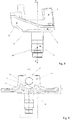
- the drawing shown shows a three-dimensional view of a steering knuckle 1 according to the invention for vehicles, with a view of the inside 9 of the steering knuckle 1.
- the steering knuckle 1 according to the invention has a stub axle 7 and a stub axle receptacle 2, the stub axle 1 being formed in one piece or in one piece and preferably as one-piece casting is made.
- the Achsfaust matter 2 includes a stub axle wall 8 on which the stub axle 7 is arranged on one side and an upper and lower Achsfaustability 3, 4 on the opposite side Kingpin (not shown) is used.
- the steering knuckle wall 8 has a cross-sectional area 11, which in FIG Fig. 4 is clearly visible.
- the narrowest cross-sectional width 13 of the steering knuckle wall 8 is located in the Center of the cross-sectional length 14 or in alignment with the central axis of the stub axle 12.
- the cross-sectional width widens on both sides starting from the central axis of the stub axle 12 over the cross-sectional length 14 to the widest cross-sectional width of the stub axle wall 15 13 identical on both sides.
- the widening of the cross-sectional width takes place preferably only against the inside 9 of the stub axle wall, since it is not possible to widen it towards the outside due to the bearing to be arranged on the stub axle.
- this cross-sectional area 14 makes optimum use of the restricted installation space, resulting in a groove 16 along the inside 9 of the stub axle wall 8 since the cross-sectional area preferably extends between the upper and lower axle stub mounts 3, 4.
- the arrangement of a radius 17 which is concave in the stub axle wall 8 has been shown to be the preferred type of widening.
- the groove 16, which extends between the upper and lower axle stub receptacles 3, 4, is preferably constant. It is advantageous if the widest cross-sectional width 15 is at least 1.5 times wider than the narrowest cross-sectional width 13 of the stub axle wall 8.
Landscapes
- Engineering & Computer Science (AREA)
- Chemical & Material Sciences (AREA)
- Combustion & Propulsion (AREA)
- Transportation (AREA)
- Mechanical Engineering (AREA)
- Steering-Linkage Mechanisms And Four-Wheel Steering (AREA)
Description
- Die Erfindung betrifft einen Achsschenkel für Fahrzeuge, insbesondere für Nutzfahrzeuge beinhaltend einen Achszapfen, eine Achsfaustaufnahme, wobei die Achsfaustaufnahme eine Achsschenkelwandung aufweist an der der Achszapfen angeordnet ist und an der gegenüberliegenden Seite eine untere und obere Achsfaustaufnahme angeordnet sind, wobei die untere und obere Achsfaustaufnahme jeweils eine Bohrung zur Aufnahme eines Achsschenkelbolzens aufweist, wobei die Bohrungen konzentrisch zueinander verlaufen.
- Achsschenkel sind hohen Belastungen unterworfen, speziell der Achszapfen neigt gerne zu ungewollten Schwingungen. Aufgrund des engen Bauraums sind jedoch kaum Verstärkungen anbringbar. Um den hohen Anforderungen zu genügen sind deshalb Achsschenkel meist als Schmiedeteile ausgebildet da diese den hohen Anforderungen standhalten und höheren Belastungen unterzogen werden können als beispielsweise Gussteile.
- Die
EP 0 201 965 B1 offenbart eine Achsschenkelanordnung, wobei die Lageroberfläche zwischen Achsschenkelbolzen und Achsschenkel vergrössert ist um die auftretende Belastung besser zu verteilen. Das DokumentWO2012174185 offenbart einen Achsschenkel gemäß dem Oberbegriff des Anspruchs 1. - Es ist Aufgabe der Erfindung einen Achsschenkel vorzuschlagen der höheren Belastungen stand hält und die Schwingfestigkeit am Achszapfen verbessert wird.
- Diese Aufgabe wird erfindungsgemäss dadurch gelöst, dass der Querschnitt der Achsschenkelwandung die schmalste Querschnittsbreite auf der Höhe der Mittelachse Achszapfen aufweist und sich die Querschnittsbreite der Achsschenkelwandung mit Entfernung zur Mittelachse Achszapfen verbreitert.
- Der erfindungsgemässe Achsschenkel für Fahrzeuge, insbesondere für Nutzfahrzeuge beinhaltend einen Achszapfen und eine Achsfaustaufnahme, wobei der Achsschenkel einteilig ausgebildet ist vorzugsweise als Gussteil. Die Achsfaustaufnahme weist eine Achsschenkelwandung auf an der der Achszapfen auf der einen Seite angeordnet ist. Auf der gegenüberliegenden Seite der Achsschenkelwandung sind eine untere und obere Achsfaustaufnahme angeordnet. Die untere und obere Achsfaustanordnung weisen jeweils eine Bohrung zur Aufnahme eines Achsschenkelbolzens auf, wobei die Bohrungen konzentrisch zueinander angeordnet sind. Der Querschnitt der Achsschenkelwandung weist die schmalste Querschnittsbreite auf der Höhe der Mittelachse Achszapfen auf, wobei sich die Querschnittsbreite der Achsschenkelwandung mit Entfernung zur Mittelachse Achszapfen verbreitert, vorzugsweise über die Querschnittslänge der Achsschenkelwandung. Die Verbreiterung des Querschnitts findet vorzugsweise ausschliesslich innenseitig der Achsschenkelwandung statt. Durch die erfindungsgemässe Ausgestaltung des Achsschenkels bzw. der Achsschenkelwandung wird eine höhere Belastbarkeit des Achsschenkels bzw. eine höhere Schwingfestigkeit des Achszapfens erreicht trotz dem begrenzten Bauraum der zur Verfügung steht.
- Vorzugsweise erstreckt sich die Verbreiterung der Querschnittsbreite über die Querschnittslänge der Achsschenkelwandung, wobei die schmalste Querschnittsbreite in der Mitte der Querschnittslänge der Achsschenkelwandung ist und ausgehend von der Mitte eine vorzugsweise auf beide Seiten identische Verbreiterung der Querschnittsbreite erfolgt. Es ist vorteilhaft, wenn sich die Verbreiterung konstant verhält.
- Als bevorzugte Ausführungsform hat sich gezeigt, wenn die Achsschenkelwandung innenseitig einen Radius aufweist der konkav verläuft. Dies ermöglicht eine optimale Ausnutzung des vorhandenen Platzes zur Vorsehung einer Verstärkung der Achsschenkelwandung.
- Gemäss einer bevorzugten Ausgestaltung hat sich gezeigt, dass die breiteste Querschnittsbreite der Achsschenkelwandung mindestens 1.5mal breiter ist als die schmalste Querschnittsbreite der Achsschenkelwandung. Die schmalste Querschnittsbreite befindet sich in der Mitte der Querschnittslänge bzw. ist auf der Höhe der Mittelachse Achszapfen angeordnet.
- Erfindungsgemäß erstreckt sich der Querschnitt der Achsschenkelwandung zwischen der oberen und unteren Achsfaustaufnahme, wobei sich eine Nut entlang der Achsschenkelwandung innenseitig erstreckt. Der sich ersteckende Querschnitt der Achsschenkelwandung mit der schmalsten Querschnittsbreite in der Mitte und sich in beide Richtungen verbreiternde Querschnittsbreite über die Querschnittslänge erstreckt sich zwischen der oberen und unteren Achsfaustaufnahme und bildet dadurch einseitig der Achsschenkelwandung eine Nut.
- Der Achsschenkel ist vorzugsweise als Gussteil ausgebildet.
- Als weitere vorteilhafte Ausgestaltung ist der Achsschenkel als Eisengussteil speziell bevorzugt GJS-Gussteil oder Sibodour-Gussteil ausgebildet ist.
- Alle Ausgestaltungmöglichkeiten sind untereinander frei kombinierbar.
- Ein Ausführungsbeispiel der Erfindung wird anhand der Figuren beschrieben, wobei sich die Erfindung nicht nur auf das Ausführungsbeispiel beschränkt. Es zeigen:
- Fig. 1
- eine dreidimensionale Ansicht eines erfindungsgemässen Achsschenkels,
- Fig. 2
- eine weitere dreidimensionale Ansicht eines erfindungsgemässen Achsschenkels,
- Fig. 3
- eine Seitenansicht eines erfindungsgemässen Achsschenkels und
- Fig. 4
- eine Schnittansicht eines erfindungsgemässen Achsschenkels.
- Die in
Fig. 1 und 2 dargestellte Zeichnung zeigt eine dreidimensionale Ansicht eines erfindungsgemässen Achsschenkel 1 für Fahrzeuge, mit Sicht auf die Innenseite 9 des Achsschenkels 1. Der erfindungsgemässe Achsschenkel 1 weist einen Achszapfen 7 sowie eine Achsfaustaufnahme 2 auf, wobei der Achsschenkel 1 einteilig bzw. einstückig ausgebildet ist und vorzugsweise als einteiliges Gussteil hergestellt ist. Die Achsfaustaufnahme 2 beinhaltet eine Achsschenkelwandung 8 an der auf der einen Seite der Achszapfen 7 angeordnet ist und an der gegenüberliegenden Seite eine obere und untere Achsfaustaufnahme 3, 4. In den Achsfaustaufnahmen 3, 4 ist jeweils eine Bohrung 5, 6 angeordnet die zur Aufnahme des Achsschenkelbolzens (nicht dargestellt) dient. Die Achsschenkelwandung 8 weist eine Querschnittsfläche 11 auf, welche inFig. 4 gut ersichtlich ist. Die schmalste Querschnittsbreite 13 der Achsschenkelwandung 8 befindet sich in der Mitte der Querschnittslänge 14 bzw. fluchtend zur Mittelachse Achszapfen 12. Die Querschnittsbreite verbreitert sich beidseitig ausgehend von der Mittelachse Achszapfen 12 über die Querschnittslänge 14 bis zur breitesten Querschnittsbreite Achsschenkelwandung 15. Vorzugsweise ist die Zunahme der Breite des Querschnitts der Achsschenkelwandung 8 ausgehend von der schmalsten Querschnittsbreite 13 auf beide Seiten identisch. Die Verbreiterung der Querschnittsbreite findet vorzugsweise nur gegen die Innenseite 9 der Achsschenkelwandung statt, da aufgrund der auf dem Achszapfen anzuordnenden Lagerung eine Verbreiterung nach aussen nicht möglich ist. Durch die Ausgestaltung dieser Querschnittsfläche 14 wird der beengte Bauraum optimal ausgenutzt, wobei sich dadurch eine Nut 16 entlang der Innenseite 9 der Achsschenkelwandung 8 ergibt da sich die Querschnittsfläche vorzugsweise zwischen der oberen und unteren Achsfaustaufnahme 3, 4 erstreckt. Als bevorzugte Art der Verbreiterung hat sich die Anordnung eines Radius 17 gezeigt, welcher konkav in der Achsschenkelwandung 8 angeordnet ist. Vorzugsweise verläuft die Nut 16, welche sich zwischen der oberen und unteren Achsfaustaufnahme 3, 4 erstreckt, konstant. Vorteilhaft ist es, wenn die breiteste Querschnittsbreite 15 mindestens 1.5mal breiter als die schmalste Querschnittsbreite 13 der Achsschenkelwandung 8 ist. -
- 1
- Achsschenkel
- 2
- Achsfaustaufnahme
- 3
- Obere Achsfaustaufnahme
- 4
- Untere Achsfaustaufnahme
- 5
- Obere Bohrung
- 6
- Untere Bohrung
- 7
- Achszapfen
- 8
- Achsschenkelwandung
- 9
- Achsschenkelwandung innenseitig
- 10
- Achsschenkelwandung aussenseitig
- 11
- Achsschenkelwandung Querschnittsfläche
- 12
- Mittelachse Achszapfen
- 13
- Schmalste Querschnittsbreite Achsschenkelwandung
- 14
- Querschnittslänge
- 15
- Breiteste Querschnittsbreite Achsschenkelwandung
- 16
- Nut
- 17
- Radius
Claims (6)
- Achsschenkel (1) für Fahrzeuge, insbesondere für Nutzfahrzeuge beinhaltend einen Achszapfen (7), eine Achsfaustaufnahme (2), wobei die Achsfaustaufnahme (2) eine Achsschenkelwandung (8) aufweist an der der Achszapfen (7) angeordnet ist und an der gegenüberliegenden Seite eine untere und obere Achsfaustaufnahme (3, 4) angeordnet sind, wobei die untere und obere Achsfaustaufnahme (3, 4) jeweils eine Bohrung (5, 6) zur Aufnahme eines Achsschenkelbolzens aufweist, wobei die Bohrungen (5, 6) konzentrisch zueinander verlaufen, wobei die Querschnittsfläche (11) der Achsschenkelwandung (8) die schmalste Querschnittsbreite (13) auf der Höhe der Mittelachse Achszapfen (12) aufweist und sich die Querschnittsbreite der Achsschenkelwandung (8) mit Entfernung zur Mittelachse Achszapfen (12) verbreitert, dadurch gekennzeichnet, dass die Querschnittsfläche (11) der Achsschenkelwandung (8) sich zwischen der oberen Achsfaustaufnahme (3) und der unteren Achsfaustaufnahme (4) erstreckt, wobei sich eine Nut (16) entlang der Achsschenkelwandung innenseitig (9) erstreckt.
- Achsschenkel (1) nach Anspruch 1, dadurch gekennzeichnet, dass sich die Verbreiterung der Querschnittsbreite über die Querschnittsläng (14) der Achsschenkelwandung (8) erstreckt, wobei die schmalste Querschnittsbreite (13) in der Mitte der Querschnittslänge (14) der Achsschenkelwandung (8) ist und ausgehend von der Mitte eine vorzugsweise auf beide Seite identische Verbreiterung der Querschnittsbreite erfolgt.
- Achsschenkel (1) nach Anspruch 1 oder 2, dadurch gekennzeichnet, dass die Achsschenkelwandung (8) innenseitig einen Radius (17) aufweist der konkav verläuft.
- Achsschenkel nach einem der Ansprüche 1 bis 3, dadurch gekennzeichnet, dass die breiteste Querschnittsbreite der Achsschenkelwandung mindestens 1.5mal breiter ist als die schmalste Querschnittsbreite der Achsschenkelwandung .
- Achsschenkel (1) nach einem der Ansprüche 1 bis 4, dadurch gekennzeichnet, dass der Achsschenkel (1) als Gussteil ausgebildet ist.
- Achsschenkel (1) nach einem der Ansprüche 1 bis 5, dadurch gekennzeichnet, dass der Achsschenkel (1) als Eisengussteil vorzugsweise GJS-Gussteil oder Sibodour-Gussteil ausgebildet ist.
Priority Applications (2)
| Application Number | Priority Date | Filing Date | Title |
|---|---|---|---|
| EP18205215.9A EP3650313B1 (de) | 2018-11-08 | 2018-11-08 | Achsschenkel |
| CN201911089151.8A CN111152840B (zh) | 2018-11-08 | 2019-11-08 | 转向节 |
Applications Claiming Priority (1)
| Application Number | Priority Date | Filing Date | Title |
|---|---|---|---|
| EP18205215.9A EP3650313B1 (de) | 2018-11-08 | 2018-11-08 | Achsschenkel |
Publications (2)
| Publication Number | Publication Date |
|---|---|
| EP3650313A1 EP3650313A1 (de) | 2020-05-13 |
| EP3650313B1 true EP3650313B1 (de) | 2021-10-13 |
Family
ID=64267684
Family Applications (1)
| Application Number | Title | Priority Date | Filing Date |
|---|---|---|---|
| EP18205215.9A Active EP3650313B1 (de) | 2018-11-08 | 2018-11-08 | Achsschenkel |
Country Status (2)
| Country | Link |
|---|---|
| EP (1) | EP3650313B1 (de) |
| CN (1) | CN111152840B (de) |
Family Cites Families (6)
| Publication number | Priority date | Publication date | Assignee | Title |
|---|---|---|---|---|
| US4635952A (en) | 1985-05-07 | 1987-01-13 | V. W. Kaiser Engineering, Inc. | Steering knuckle and kingpin assembly |
| DE102008000058A1 (de) * | 2008-01-15 | 2009-07-16 | Zf Friedrichshafen Ag | Achsschenkel einer Einzelradaufhängung eines Kraftfahrzeugs |
| WO2012174185A1 (en) * | 2011-06-15 | 2012-12-20 | Daimler Trucks North America Llc | Steering knuckles with integrated arms |
| CN203460926U (zh) * | 2013-07-05 | 2014-03-05 | 上汽通用五菱汽车股份有限公司 | 一种整体式转向节 |
| CN207311594U (zh) * | 2017-08-26 | 2018-05-04 | 宁波远通和道汽车部件有限公司 | 一种汽车转向节的转动结构 |
| CN207510500U (zh) * | 2017-11-27 | 2018-06-19 | 湖南中联重科车桥有限公司 | 转向节、转向桥和车辆 |
-
2018
- 2018-11-08 EP EP18205215.9A patent/EP3650313B1/de active Active
-
2019
- 2019-11-08 CN CN201911089151.8A patent/CN111152840B/zh active Active
Also Published As
| Publication number | Publication date |
|---|---|
| EP3650313A1 (de) | 2020-05-13 |
| CN111152840A (zh) | 2020-05-15 |
| CN111152840B (zh) | 2023-02-10 |
Similar Documents
| Publication | Publication Date | Title |
|---|---|---|
| EP2671741B2 (de) | Querlenker sowie Verfahren zum Herstellen des Querlenkers | |
| EP2614969B1 (de) | Schwenklager mit gedrehter Dämpferklemmung | |
| EP1167092A2 (de) | Querlenker einer Radaufhängung | |
| DE4313624A1 (de) | Achsschenkelanordnung | |
| EP2918430B1 (de) | Fahrwerkslenker für ein Kraftfahrzeug | |
| DE19543690A1 (de) | Verbindung eines Stabilisators mit der Radaufhängung eines Kraftfahrzeuges | |
| DE102017203711B4 (de) | Kugelgelenk | |
| DE102016200609A1 (de) | Gerader Zweipunktlenker, insbesondere gerade Achsstrebe für ein Nutzfahrzeug | |
| DE102013210142A1 (de) | Lenkereinheit | |
| EP3409513B1 (de) | Schwenklager | |
| DE102009031289B4 (de) | Stabilisatorstrebe | |
| EP1165984B1 (de) | Gummilager | |
| EP4360919B1 (de) | Federlenker | |
| EP3191321B1 (de) | Achseinheit | |
| DE102014218323B4 (de) | Achseinheit | |
| EP3650313A1 (de) | Achsschenkel | |
| EP3208105B1 (de) | Achskörper | |
| EP3855039B1 (de) | Aus gusseisen bestehender bremssattel | |
| DE10359876B4 (de) | Einrollige Unterflasche für Hebezeuge | |
| DE102012214416A1 (de) | Stehlagergehäuse | |
| DE102009038952B4 (de) | Radnabe | |
| EP1270969B1 (de) | Kugelgelenk | |
| DE102024114742B3 (de) | Starres Verbindungsteil zur mechanischen Kopplung eines ersten Bauteils und eines zweiten Bauteils | |
| DE102023114509B3 (de) | Halteanordnung für ein Feder- und/oder Dämpferelement einer Hinterachse an einem Hecklängsträger eines Kraftwagens | |
| EP3199828A1 (de) | Bremsbelaghalterung einer fahrzeug-scheibenbremse sowie niederhalter für die befestigung von bremsbelägen |
Legal Events
| Date | Code | Title | Description |
|---|---|---|---|
| PUAI | Public reference made under article 153(3) epc to a published international application that has entered the european phase |
Free format text: ORIGINAL CODE: 0009012 |
|
| STAA | Information on the status of an ep patent application or granted ep patent |
Free format text: STATUS: THE APPLICATION HAS BEEN PUBLISHED |
|
| AK | Designated contracting states |
Kind code of ref document: A1 Designated state(s): AL AT BE BG CH CY CZ DE DK EE ES FI FR GB GR HR HU IE IS IT LI LT LU LV MC MK MT NL NO PL PT RO RS SE SI SK SM TR |
|
| AX | Request for extension of the european patent |
Extension state: BA ME |
|
| STAA | Information on the status of an ep patent application or granted ep patent |
Free format text: STATUS: REQUEST FOR EXAMINATION WAS MADE |
|
| 17P | Request for examination filed |
Effective date: 20201022 |
|
| RBV | Designated contracting states (corrected) |
Designated state(s): AL AT BE BG CH CY CZ DE DK EE ES FI FR GB GR HR HU IE IS IT LI LT LU LV MC MK MT NL NO PL PT RO RS SE SI SK SM TR |
|
| GRAP | Despatch of communication of intention to grant a patent |
Free format text: ORIGINAL CODE: EPIDOSNIGR1 |
|
| STAA | Information on the status of an ep patent application or granted ep patent |
Free format text: STATUS: GRANT OF PATENT IS INTENDED |
|
| INTG | Intention to grant announced |
Effective date: 20210706 |
|
| GRAS | Grant fee paid |
Free format text: ORIGINAL CODE: EPIDOSNIGR3 |
|
| GRAA | (expected) grant |
Free format text: ORIGINAL CODE: 0009210 |
|
| STAA | Information on the status of an ep patent application or granted ep patent |
Free format text: STATUS: THE PATENT HAS BEEN GRANTED |
|
| AK | Designated contracting states |
Kind code of ref document: B1 Designated state(s): AL AT BE BG CH CY CZ DE DK EE ES FI FR GB GR HR HU IE IS IT LI LT LU LV MC MK MT NL NO PL PT RO RS SE SI SK SM TR |
|
| REG | Reference to a national code |
Ref country code: GB Ref legal event code: FG4D Free format text: NOT ENGLISH |
|
| REG | Reference to a national code |
Ref country code: CH Ref legal event code: EP |
|
| REG | Reference to a national code |
Ref country code: DE Ref legal event code: R096 Ref document number: 502018007420 Country of ref document: DE |
|
| REG | Reference to a national code |
Ref country code: IE Ref legal event code: FG4D Free format text: LANGUAGE OF EP DOCUMENT: GERMAN |
|
| REG | Reference to a national code |
Ref country code: AT Ref legal event code: REF Ref document number: 1438004 Country of ref document: AT Kind code of ref document: T Effective date: 20211115 |
|
| REG | Reference to a national code |
Ref country code: LT Ref legal event code: MG9D |
|
| REG | Reference to a national code |
Ref country code: NL Ref legal event code: MP Effective date: 20211013 |
|
| PG25 | Lapsed in a contracting state [announced via postgrant information from national office to epo] |
Ref country code: RS Free format text: LAPSE BECAUSE OF FAILURE TO SUBMIT A TRANSLATION OF THE DESCRIPTION OR TO PAY THE FEE WITHIN THE PRESCRIBED TIME-LIMIT Effective date: 20211013 Ref country code: LT Free format text: LAPSE BECAUSE OF FAILURE TO SUBMIT A TRANSLATION OF THE DESCRIPTION OR TO PAY THE FEE WITHIN THE PRESCRIBED TIME-LIMIT Effective date: 20211013 Ref country code: FI Free format text: LAPSE BECAUSE OF FAILURE TO SUBMIT A TRANSLATION OF THE DESCRIPTION OR TO PAY THE FEE WITHIN THE PRESCRIBED TIME-LIMIT Effective date: 20211013 Ref country code: BG Free format text: LAPSE BECAUSE OF FAILURE TO SUBMIT A TRANSLATION OF THE DESCRIPTION OR TO PAY THE FEE WITHIN THE PRESCRIBED TIME-LIMIT Effective date: 20220113 |
|
| PG25 | Lapsed in a contracting state [announced via postgrant information from national office to epo] |
Ref country code: IS Free format text: LAPSE BECAUSE OF FAILURE TO SUBMIT A TRANSLATION OF THE DESCRIPTION OR TO PAY THE FEE WITHIN THE PRESCRIBED TIME-LIMIT Effective date: 20220213 Ref country code: SE Free format text: LAPSE BECAUSE OF FAILURE TO SUBMIT A TRANSLATION OF THE DESCRIPTION OR TO PAY THE FEE WITHIN THE PRESCRIBED TIME-LIMIT Effective date: 20211013 Ref country code: PT Free format text: LAPSE BECAUSE OF FAILURE TO SUBMIT A TRANSLATION OF THE DESCRIPTION OR TO PAY THE FEE WITHIN THE PRESCRIBED TIME-LIMIT Effective date: 20220214 Ref country code: PL Free format text: LAPSE BECAUSE OF FAILURE TO SUBMIT A TRANSLATION OF THE DESCRIPTION OR TO PAY THE FEE WITHIN THE PRESCRIBED TIME-LIMIT Effective date: 20211013 Ref country code: NO Free format text: LAPSE BECAUSE OF FAILURE TO SUBMIT A TRANSLATION OF THE DESCRIPTION OR TO PAY THE FEE WITHIN THE PRESCRIBED TIME-LIMIT Effective date: 20220113 Ref country code: NL Free format text: LAPSE BECAUSE OF FAILURE TO SUBMIT A TRANSLATION OF THE DESCRIPTION OR TO PAY THE FEE WITHIN THE PRESCRIBED TIME-LIMIT Effective date: 20211013 Ref country code: LV Free format text: LAPSE BECAUSE OF FAILURE TO SUBMIT A TRANSLATION OF THE DESCRIPTION OR TO PAY THE FEE WITHIN THE PRESCRIBED TIME-LIMIT Effective date: 20211013 Ref country code: HR Free format text: LAPSE BECAUSE OF FAILURE TO SUBMIT A TRANSLATION OF THE DESCRIPTION OR TO PAY THE FEE WITHIN THE PRESCRIBED TIME-LIMIT Effective date: 20211013 Ref country code: GR Free format text: LAPSE BECAUSE OF FAILURE TO SUBMIT A TRANSLATION OF THE DESCRIPTION OR TO PAY THE FEE WITHIN THE PRESCRIBED TIME-LIMIT Effective date: 20220114 Ref country code: ES Free format text: LAPSE BECAUSE OF FAILURE TO SUBMIT A TRANSLATION OF THE DESCRIPTION OR TO PAY THE FEE WITHIN THE PRESCRIBED TIME-LIMIT Effective date: 20211013 |
|
| REG | Reference to a national code |
Ref country code: CH Ref legal event code: PL |
|
| REG | Reference to a national code |
Ref country code: DE Ref legal event code: R097 Ref document number: 502018007420 Country of ref document: DE |
|
| PG25 | Lapsed in a contracting state [announced via postgrant information from national office to epo] |
Ref country code: SM Free format text: LAPSE BECAUSE OF FAILURE TO SUBMIT A TRANSLATION OF THE DESCRIPTION OR TO PAY THE FEE WITHIN THE PRESCRIBED TIME-LIMIT Effective date: 20211013 Ref country code: SK Free format text: LAPSE BECAUSE OF FAILURE TO SUBMIT A TRANSLATION OF THE DESCRIPTION OR TO PAY THE FEE WITHIN THE PRESCRIBED TIME-LIMIT Effective date: 20211013 Ref country code: RO Free format text: LAPSE BECAUSE OF FAILURE TO SUBMIT A TRANSLATION OF THE DESCRIPTION OR TO PAY THE FEE WITHIN THE PRESCRIBED TIME-LIMIT Effective date: 20211013 Ref country code: MC Free format text: LAPSE BECAUSE OF FAILURE TO SUBMIT A TRANSLATION OF THE DESCRIPTION OR TO PAY THE FEE WITHIN THE PRESCRIBED TIME-LIMIT Effective date: 20211013 Ref country code: LU Free format text: LAPSE BECAUSE OF NON-PAYMENT OF DUE FEES Effective date: 20211108 Ref country code: EE Free format text: LAPSE BECAUSE OF FAILURE TO SUBMIT A TRANSLATION OF THE DESCRIPTION OR TO PAY THE FEE WITHIN THE PRESCRIBED TIME-LIMIT Effective date: 20211013 Ref country code: DK Free format text: LAPSE BECAUSE OF FAILURE TO SUBMIT A TRANSLATION OF THE DESCRIPTION OR TO PAY THE FEE WITHIN THE PRESCRIBED TIME-LIMIT Effective date: 20211013 Ref country code: CZ Free format text: LAPSE BECAUSE OF FAILURE TO SUBMIT A TRANSLATION OF THE DESCRIPTION OR TO PAY THE FEE WITHIN THE PRESCRIBED TIME-LIMIT Effective date: 20211013 Ref country code: BE Free format text: LAPSE BECAUSE OF NON-PAYMENT OF DUE FEES Effective date: 20211130 |
|
| REG | Reference to a national code |
Ref country code: BE Ref legal event code: MM Effective date: 20211130 |
|
| PLBE | No opposition filed within time limit |
Free format text: ORIGINAL CODE: 0009261 |
|
| STAA | Information on the status of an ep patent application or granted ep patent |
Free format text: STATUS: NO OPPOSITION FILED WITHIN TIME LIMIT |
|
| PG25 | Lapsed in a contracting state [announced via postgrant information from national office to epo] |
Ref country code: LI Free format text: LAPSE BECAUSE OF NON-PAYMENT OF DUE FEES Effective date: 20211130 Ref country code: CH Free format text: LAPSE BECAUSE OF NON-PAYMENT OF DUE FEES Effective date: 20211130 |
|
| 26N | No opposition filed |
Effective date: 20220714 |
|
| PG25 | Lapsed in a contracting state [announced via postgrant information from national office to epo] |
Ref country code: IE Free format text: LAPSE BECAUSE OF NON-PAYMENT OF DUE FEES Effective date: 20211108 Ref country code: AL Free format text: LAPSE BECAUSE OF FAILURE TO SUBMIT A TRANSLATION OF THE DESCRIPTION OR TO PAY THE FEE WITHIN THE PRESCRIBED TIME-LIMIT Effective date: 20211013 |
|
| PG25 | Lapsed in a contracting state [announced via postgrant information from national office to epo] |
Ref country code: SI Free format text: LAPSE BECAUSE OF FAILURE TO SUBMIT A TRANSLATION OF THE DESCRIPTION OR TO PAY THE FEE WITHIN THE PRESCRIBED TIME-LIMIT Effective date: 20211013 Ref country code: FR Free format text: LAPSE BECAUSE OF NON-PAYMENT OF DUE FEES Effective date: 20211213 |
|
| PG25 | Lapsed in a contracting state [announced via postgrant information from national office to epo] |
Ref country code: IT Free format text: LAPSE BECAUSE OF FAILURE TO SUBMIT A TRANSLATION OF THE DESCRIPTION OR TO PAY THE FEE WITHIN THE PRESCRIBED TIME-LIMIT Effective date: 20211013 |
|
| PG25 | Lapsed in a contracting state [announced via postgrant information from national office to epo] |
Ref country code: CY Free format text: LAPSE BECAUSE OF FAILURE TO SUBMIT A TRANSLATION OF THE DESCRIPTION OR TO PAY THE FEE WITHIN THE PRESCRIBED TIME-LIMIT Effective date: 20211013 |
|
| P01 | Opt-out of the competence of the unified patent court (upc) registered |
Effective date: 20230529 |
|
| GBPC | Gb: european patent ceased through non-payment of renewal fee |
Effective date: 20221108 |
|
| PG25 | Lapsed in a contracting state [announced via postgrant information from national office to epo] |
Ref country code: HU Free format text: LAPSE BECAUSE OF FAILURE TO SUBMIT A TRANSLATION OF THE DESCRIPTION OR TO PAY THE FEE WITHIN THE PRESCRIBED TIME-LIMIT; INVALID AB INITIO Effective date: 20181108 |
|
| PG25 | Lapsed in a contracting state [announced via postgrant information from national office to epo] |
Ref country code: GB Free format text: LAPSE BECAUSE OF NON-PAYMENT OF DUE FEES Effective date: 20221108 |
|
| PG25 | Lapsed in a contracting state [announced via postgrant information from national office to epo] |
Ref country code: MK Free format text: LAPSE BECAUSE OF FAILURE TO SUBMIT A TRANSLATION OF THE DESCRIPTION OR TO PAY THE FEE WITHIN THE PRESCRIBED TIME-LIMIT Effective date: 20211013 |
|
| PG25 | Lapsed in a contracting state [announced via postgrant information from national office to epo] |
Ref country code: TR Free format text: LAPSE BECAUSE OF FAILURE TO SUBMIT A TRANSLATION OF THE DESCRIPTION OR TO PAY THE FEE WITHIN THE PRESCRIBED TIME-LIMIT Effective date: 20211013 |
|
| PG25 | Lapsed in a contracting state [announced via postgrant information from national office to epo] |
Ref country code: MT Free format text: LAPSE BECAUSE OF FAILURE TO SUBMIT A TRANSLATION OF THE DESCRIPTION OR TO PAY THE FEE WITHIN THE PRESCRIBED TIME-LIMIT Effective date: 20211013 |
|
| REG | Reference to a national code |
Ref country code: AT Ref legal event code: MM01 Ref document number: 1438004 Country of ref document: AT Kind code of ref document: T Effective date: 20231108 |
|
| PG25 | Lapsed in a contracting state [announced via postgrant information from national office to epo] |
Ref country code: AT Free format text: LAPSE BECAUSE OF NON-PAYMENT OF DUE FEES Effective date: 20231108 |
|
| PG25 | Lapsed in a contracting state [announced via postgrant information from national office to epo] |
Ref country code: AT Free format text: LAPSE BECAUSE OF NON-PAYMENT OF DUE FEES Effective date: 20231108 |
|
| PGFP | Annual fee paid to national office [announced via postgrant information from national office to epo] |
Ref country code: DE Payment date: 20251119 Year of fee payment: 8 |
|
| PGFP | Annual fee paid to national office [announced via postgrant information from national office to epo] |
Ref country code: AT Payment date: 20260410 Year of fee payment: 5 |