EP3649896A1 - Entraînement électromoteur pour meubles et meuble fonctionel avec un tel entraînement - Google Patents
Entraînement électromoteur pour meubles et meuble fonctionel avec un tel entraînement Download PDFInfo
- Publication number
- EP3649896A1 EP3649896A1 EP19218908.2A EP19218908A EP3649896A1 EP 3649896 A1 EP3649896 A1 EP 3649896A1 EP 19218908 A EP19218908 A EP 19218908A EP 3649896 A1 EP3649896 A1 EP 3649896A1
- Authority
- EP
- European Patent Office
- Prior art keywords
- furniture
- functional
- evaluation circuit
- sensor
- drive
- Prior art date
- Legal status (The legal status is an assumption and is not a legal conclusion. Google has not performed a legal analysis and makes no representation as to the accuracy of the status listed.)
- Granted
Links
Images

Classifications
-
- A—HUMAN NECESSITIES
- A47—FURNITURE; DOMESTIC ARTICLES OR APPLIANCES; COFFEE MILLS; SPICE MILLS; SUCTION CLEANERS IN GENERAL
- A47C—CHAIRS; SOFAS; BEDS
- A47C20/00—Head-, foot- or like rests for beds, sofas or the like
- A47C20/04—Head-, foot- or like rests for beds, sofas or the like with adjustable inclination
- A47C20/041—Head-, foot- or like rests for beds, sofas or the like with adjustable inclination by electric motors
-
- A—HUMAN NECESSITIES
- A47—FURNITURE; DOMESTIC ARTICLES OR APPLIANCES; COFFEE MILLS; SPICE MILLS; SUCTION CLEANERS IN GENERAL
- A47C—CHAIRS; SOFAS; BEDS
- A47C31/00—Details or accessories for chairs, beds, or the like, not provided for in other groups of this subclass, e.g. upholstery fasteners, mattress protectors, stretching devices for mattress nets
- A47C31/008—Use of remote controls
-
- A—HUMAN NECESSITIES
- A61—MEDICAL OR VETERINARY SCIENCE; HYGIENE
- A61G—TRANSPORT, PERSONAL CONVEYANCES, OR ACCOMMODATION SPECIALLY ADAPTED FOR PATIENTS OR DISABLED PERSONS; OPERATING TABLES OR CHAIRS; CHAIRS FOR DENTISTRY; FUNERAL DEVICES
- A61G7/00—Beds specially adapted for nursing; Devices for lifting patients or disabled persons
- A61G7/002—Beds specially adapted for nursing; Devices for lifting patients or disabled persons having adjustable mattress frame
- A61G7/015—Beds specially adapted for nursing; Devices for lifting patients or disabled persons having adjustable mattress frame divided into different adjustable sections, e.g. for Gatch position
-
- A—HUMAN NECESSITIES
- A61—MEDICAL OR VETERINARY SCIENCE; HYGIENE
- A61G—TRANSPORT, PERSONAL CONVEYANCES, OR ACCOMMODATION SPECIALLY ADAPTED FOR PATIENTS OR DISABLED PERSONS; OPERATING TABLES OR CHAIRS; CHAIRS FOR DENTISTRY; FUNERAL DEVICES
- A61G7/00—Beds specially adapted for nursing; Devices for lifting patients or disabled persons
- A61G7/002—Beds specially adapted for nursing; Devices for lifting patients or disabled persons having adjustable mattress frame
- A61G7/018—Control or drive mechanisms
-
- A—HUMAN NECESSITIES
- A61—MEDICAL OR VETERINARY SCIENCE; HYGIENE
- A61G—TRANSPORT, PERSONAL CONVEYANCES, OR ACCOMMODATION SPECIALLY ADAPTED FOR PATIENTS OR DISABLED PERSONS; OPERATING TABLES OR CHAIRS; CHAIRS FOR DENTISTRY; FUNERAL DEVICES
- A61G2203/00—General characteristics of devices
- A61G2203/10—General characteristics of devices characterised by specific control means, e.g. for adjustment or steering
- A61G2203/12—Remote controls
Definitions
- the invention relates to an electromotive furniture drive for adjusting movable furniture parts of a functional piece of furniture, comprising a control device, at least one adjusting drive with an electric motor and at least one evaluation circuit with an input, which can be electrically conductively connected together with a sensor attached to the functional piece of furniture and an approximation and / or forms a touch detector.
- the invention also relates to functional furniture with such an electromotive furniture drive.
- Electromotive furniture drives of this type are known and include, for example, a number of adjustment drives, for example linear drives.
- a linear drive generates a linear movement on a driven member and has at least one electric motor, a gear train and the driven member, the gear train with the driven member being connected downstream of the electric motor.
- the linear drive and its output member are connected to furniture components and move or adjust them relative to one another when the motors are operating.
- the furniture components are e.g. movably connected to a base frame and / or to one another by so-called functional or movement fittings. These fittings are usually made of metallic materials, such as Stole.
- a functional piece of furniture is provided with at least one electromotive furniture drive.
- Such an electromotive furniture drive is mounted in the furniture, which has fixed and movable furniture components.
- Fixed furniture components are e.g. Frame components.
- Movable furniture components are e.g. firm or resilient support surfaces of an upholstery or mattress of the seating and / or reclining furniture as well as sections or elements of the furniture that can be adjusted manually or by an electric motor.
- the electromotive furniture drive is used to adjust the movable furniture components.
- the adjustment movement and driving force generated by the electromotive furniture drive is transmitted to the respective movable furniture component, wherein the electromotive furniture drive is supported on a fixed furniture component and the movable furniture component is adjusted relative to the fixed furniture component.
- the electromotive furniture drive can also be attached between two movable furniture components, whereby it can be adjusted relative to one another.
- Electromotive furniture drives are known from the prior art in a variety of different designs for different applications and purposes, e.g. as single drives, double and multiple drives.
- Control devices are also known, which are designed to control the respective electric motor of an adjustment drive on command or as a result of an event, e.g. to control a control command of a manual control, a limit switch, a detector, etc.
- the control devices have inputs and outputs.
- the outputs are electrically conductively connected to the respective electric motor, for example.
- the inputs are connected, for example, to manual remote controls or, if necessary via evaluation circuits, to sensors and detectors in an electrically conductive manner.
- Other control devices have other outputs which exclusively transmit an electrical or an electromechanical signal to a further control device which have the previously described outputs for operating the respective electric motor.
- control devices described at the outset have proven their worth. From the publication DE 297 07 795 U1 a control device with an input is known, the input being electrically conductively connected to a metallic functional fitting, for example via a connecting line.
- the functional fitting or parts of the functional fitting forms / form a detector together with an evaluation circuit of the control device and the connecting line.
- the evaluation circuit of the control device determines the level of the electrical capacity of the functional fitting with respect to a reference variable, for example the floor, via said connecting line. Furthermore, the control device determines the change over time in the measured variable of the electrical capacitance detected by the evaluation circuit.
- Rapid changes in the electrical capacity of the functional fitting during the operation of the engine indicate a fault, for example the occurrence of an upcoming or imminent pinching of an object or a body part, provided that a person or an object moves into a danger zone of the functional fitting or touches it.
- the respective electric motor is then switched off and, if necessary, reversed for a short period.
- the term “functional fitting” also includes metallic frames and parts, such as Feet to understand functional furniture.
- the term “sensor” here means an element of a functional fitting or a separate, electrically conductive element, such as e.g. a cable, rod antenna, flat iron, etc., which is attached to the furniture.
- control device mentioned at the outset has proven its worth.
- large pieces of furniture such as with wide beds or with complex pieces of furniture, such as when the functional fittings are divided into several groups.
- groups can be formed if, for example, in a bed an upper frame is connected to a lower frame via electrically insulating rollers or sliders.
- a further group can be formed if a foot flap fitting section of a functional fitting of an armchair with plastic bearings is arranged in an electrically insulated manner from the base frame.
- Other groups can be formed if the piece of furniture has a plurality of functional fittings, which are each used for partial areas of the piece of furniture.
- the invention is based on the object of providing an electromotive furniture drive with a control device of the type mentioned, the disadvantages described no longer occurring or being reduced significantly, and which is also easy to assemble and is easy to handle.
- the task is solved by arranging more than one proximity and / or touch detector on a functional piece of furniture.
- a sensor or a group of sensors with an evaluation circuit forms such a detector, each sensor or group of sensors being connected to an input of the evaluation circuit.
- the piece of furniture has a plurality of detectors, which are individually connected in an electrically conductive manner to an input of the evaluation circuit of the control device.
- the design of the various detectors makes it possible to reliably monitor even a large functional fitting, such as the bed shown as functional furniture, without having to ensure that furniture parts to be monitored are galvanically connected to one another or that there is sufficient capacitive coupling of the furniture parts is given among themselves.
- the division of the movable furniture parts to be monitored in a functional piece of furniture for anti-trap protection into at least two groups, which are assigned to different detectors, also prevents an undesirable false response due to interference radiation, which can otherwise be coupled in more easily if the sensor surface is otherwise too large.
- the control device has an evaluation circuit with a plurality of at least two inputs, each input being coupled to a sensor or a group of sensors.
- the evaluation circuit has a multiplexer, via which the at least two inputs can be connected sequentially to a detector circuit of the evaluation circuit. This measure of dividing into several groups combined with a sequential evaluation using only one detector circuit enables inexpensive production and easy assembly of a highly sensitive pinch protection with high operational reliability at the same time.
- the senor or the group of sensors is conductively connected to one of the inputs of the at least one evaluation circuit.
- the sensor or the group of sensors is capacitively coupled to one of the inputs of the at least one evaluation circuit.
- the senor is a sensor line and / or a conductive movable furniture part and / or a conductive element of a functional fitting.
- a functional furniture according to the invention has at least two groups of movable furniture parts and at least one electromotive furniture drive according to one of the preceding claims.
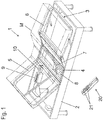
- Fig. 1 shows an exemplary furniture arrangement with a functional furniture 1.
- a bed is shown here as an example.
- the functional furniture 1 has a basic element 2, here a frame-like frame with feet.
- a slatted frame with a functional fitting 3 is inserted into the base element 2.
- the slatted frame carries a mattress M.
- the functional furniture 1 has two movable furniture parts 5 and 6, which can be moved relative to a fixed base part 4 arranged between them.
- the two movable furniture parts 5, 6 are a back part and a leg section.
- back part 5 and leg part 6 are also referred to below as back part 5 and leg part 6.
- the movable arrangement of the movable furniture parts 5 and 6 is realized by the functional fitting 3, also called a movement fitting.
- the movement is displaceable and / or pivotable.
- the movably mounted back part 5 and the leg part 6 are each coupled to an electromotive adjustment drive 7, 8.
- the back part 5 is coupled to the electromotive adjustment drive 7.
- the electromotive adjusting drive 8 is provided for moving or adjusting the leg part 6.
- the electromotive adjustment drives 7, 8 are designed here as linear drives.
- the linear drives have one or a number of electric motors, each motor being followed by a speed reduction gear with at least one gear stage.
- the speed reduction gear can be followed by a further gear, for example in the form of a threaded spindle gear, which generates a linear movement of the output member from the rotational movement of the motor.
- the last transmission link or a further link connected to it forms an output link.
- the output member of the respective electromotive adjustment drive is connected to the respective furniture component (back part 5, leg part 6) or alternatively to a component connected to the base frame 2, so that when the electric motor of the respective adjustment drive 7, 8 is in operation, the movable furniture components are adjusted relative to one another will.
- the electromotive adjustment drives 7, 8 are connected to a control device 9.
- This connection can be made, for example, as a pluggable cable connection, which is not shown here.
- the control device 9 has an electrical supply unit, which provides the electrical energy, for example from the network, for the electromotive adjusting drives 7, 8.
- the control device 9 in this example can be connected to a power connector with a power connector via a power cord (not shown).
- the mains plug leads the mains voltage on the input side to the electrical supply unit the control device 9, which emits a low voltage in the form of a DC voltage on the secondary side and forwards it to a motor controller.
- control device 9 is connected upstream of a line-dependent voltage supply, also not shown, with a mains input and with a secondary-side low-voltage output, which supplies the low-voltage in the form of a DC voltage via a line.
- An operating unit 20 is also assigned to the furniture 1, with its operating elements 21 the electromechanical adjusting drives 7, 8 can be controlled via the control device 9.
- a control signal for controlling the respective electromechanical adjustment drive 7, 8 is transmitted to the control device 9 wirelessly or by wire via a transmission link.
- the control device 9 has switching elements which convert the control signals of the transmission link into switching signals for switching the respective adjustment drive 7, 8.
- the switching elements can e.g. Relay switch and / or semiconductor switch.
- the manually operable control elements 21 of the control unit 20 generate control signals which are converted by the receiver of the control device 9 into control currents for the switching elements.
- the control elements 21 switch the control current of the relay switches or the semiconductor switches.
- the circuit breakers of the relay switches or the semiconductor switches switch the high motor current of the respective electromotive adjusting drive 7, 8.
- the functional furniture 1 shown is equipped according to the application with proximity and / or touch detectors which prevent actuation of the adjusting devices 7, 8 via the control device 9 when approaching one Sensor or a touch of the sensor is detected. This is discussed below in connection with Fig. 2 explained in more detail.
- Fig. 2 shows the system of Fig. 1 in a schematic block diagram.
- the same reference numerals in this figure denote the same or equivalent elements as in Fig. 1 .
- the furniture fitting has the two movable furniture parts, the back part 5 and the leg part 6, which are movable relative to a fixed base part 4.
- the movement is achieved via the two electromotive adjusting drives 7, 8, which act on the back part 5 and the leg part 6.
- the mechanical coupling of the adjustment drives 7, 8 on the back or leg part 5, 6 is with the Fig. 2 symbolized only by a dashed line.
- the adjustment drives 7, 8 are controlled by the control device 9 and supplied with current.
- a power supply to the control device 9, for example via an integrated or external power supply unit, is shown in FIG Fig. 2 not shown.
- an evaluation circuit 10 is provided which contacts one of the movable furniture parts 5, 6 detected.
- the evaluation circuit 10 is arranged externally by the control device 9 and is electrically connected to it via an output 13 of the evaluation circuit 10.
- the evaluation circuit 10 can be integrated in the housing of the control device 9.
- the evaluation circuit 10 has two inputs 11, 12 which are coupled to the furniture parts 5, 6 via sensor lines 111, 121.
- two sensor groups are formed, each of which comprises the sensor line 111 or 121 and the furniture part 5, 6.
- two independent contact and / or proximity detectors are formed as anti-trap protection.
- Touching or approaching the furniture parts 5, 6 is detected by the evaluation circuit 10 via the sensor lines 111, 121.
- a signal is generated at an output 13 of the evaluation circuit 10, which causes the control device 9 to stop at least one of the two adjustment drives 7, 8.
- a touch of the furniture part 5 or approach to the furniture part 5 detected via the sensor line 111 only stops the assigned adjustment drive 7, whereas the detection of a touch of the furniture part 6 or approach to the furniture part 6 via the sensor line 121 the assigned one Adjustment drive 8 stops.
- each touch regardless of which sensor line 111, 121 or which of the inputs 11, 12 of the evaluation circuit 10 detects, leads to a stopping of any adjustment drives 7, 8 which may be actuated simultaneously.
- the adjustment drives 7, 8 are not only stopped, but that a moving adjustment drive 7, 8 is operated in the reverse direction of movement for a predetermined short period after stopping, in order to release a body part that may already be jammed .
- the detection of touching of the sensors by the evaluation circuit 10 is preferably capacitive.
- This capacitive contact or proximity detection can be set so sensitively that no direct galvanic contact of an input 11 or an exposed section of the sensor line 111, 121 is required, but rather a contact or approach to insulated sections of the sensor line 111 or with it coupled furniture parts 5, 6 or sections of a functional fitting also coupled therewith can be detected. In this way, detection of contact with a painted or plastic-coated area of the movable furniture parts 5, 6 is made possible.
- a conductive element can be applied.
- the conductive element can consist in the continuation of the sensor line 111, 121 itself.
- metallized foils can, for example, be glued to the non-conductive material.
- an insulating material with a conductive coating for example based on a conductive polymer, superficially conductive. Fabrics or Yarns with woven metallic threads or fibers can be used as conductive elements.
- the sensor line 111 makes direct contact with the furniture part 5 in a conductive connection 112. If the furniture part 5 is a painted steel tube, the paint can be removed at one point, for example, and the sensor line 111 can be attached at this point. Alternatively, for example, a self-tapping screw can be screwed into the metal tube of the furniture part 5, via which the conductive connection 112 takes place.
- the sensor line 121 is coupled to the furniture part 6 via a capacitive coupling 122.
- the sensor line 121 has a flat electrode at its end, which is glued to a painted area of the furniture part 6, for example by means of a self-adhesive layer. The change in capacitance of the furniture part 6 by approaching or touching a body part is transmitted through this capacitive coupling 122 to the sensor line 121 and thus to the evaluation circuit 10.
- two inputs 11, 12 and two corresponding sensor lines 111, 121 are provided by way of example. It is understood that this number is purely exemplary. It is also possible to provide more than the two sensor lines 111, 121 shown, by means of which more than two groups of monitored movable furniture parts 5, 6 on the functional furniture 1 are defined.
- the design of the various detectors makes it possible to reliably monitor even a large functional fitting, such as, for example, in the bed shown as functional furniture 1, without having to ensure that furniture parts 5, 6 to be monitored are galvanically connected to one another or that they are sufficient capacitive coupling of the furniture parts to one another is given.
- the division of the movable furniture parts 5, 6 to be monitored overall in a functional piece of furniture for an anti-trap protection into at least two Groups that are assigned to different detectors also prevent an undesirable false response due to interference radiation, which, if the sensor area is otherwise too large, can be coupled in more easily.
- the evaluation circuit 10 can internally have a single detector circuit for the change in capacitance, which is connected in a multiplex process to the at least two inputs 11, 12 in rapid alternation (sequential evaluation). This measure of dividing into several groups and the sequential evaluation with only one detector circuit enables inexpensive production and easy assembly of a highly sensitive pinch protection with high operational reliability at the same time.
- the evaluation circuit 10 can have a number of detector circuits for a change in capacitance corresponding to the number of inputs 11, which are coupled to one another on the output side via a corresponding logic circuit, for example a "or" link, so that when each of the detector circuits responds, a corresponding output signal at the output 13 is output.
- a larger number of inputs 11, 12 can be provided, for example four inputs 11, 12, which also offers a sufficient number of groups for larger functional fittings.
- inputs 11, 12 which are not used can be set inactive, for example by connection to a ground potential.
- individual inputs 11, 12 can be selectively deactivated by parameterizing a multiplexer used on the input side or a logic used on the output side in the evaluation circuit 10.
- the detector circuits for detecting a change in capacitance are preferably self-adjusting, so that a slow change in capacitance, which is caused, for example, by changing environmental conditions such as changing air humidity, does not lead to false triggering.
- the sensor lines 111, 121 are prefers ordinary single-core cables without shielding, which are inexpensive and can be easily laid.
- one evaluation circuit each can be assigned to one control device.
Landscapes
- Health & Medical Sciences (AREA)
- Nursing (AREA)
- General Health & Medical Sciences (AREA)
- Life Sciences & Earth Sciences (AREA)
- Animal Behavior & Ethology (AREA)
- Public Health (AREA)
- Veterinary Medicine (AREA)
- Power-Operated Mechanisms For Wings (AREA)
- Elimination Of Static Electricity (AREA)
Applications Claiming Priority (3)
| Application Number | Priority Date | Filing Date | Title |
|---|---|---|---|
| DE202014104011 | 2014-08-27 | ||
| PCT/EP2015/069631 WO2016030458A1 (fr) | 2014-08-27 | 2015-08-27 | Entraînement de meuble par moteur électrique et meuble fonctionnel pourvu d'un entraînement de meuble par moteur électrique |
| EP15762948.6A EP3185724B1 (fr) | 2014-08-27 | 2015-08-27 | Meuble fonctionnel pourvu d'un entraînement de meuble par moteur électrique |
Related Parent Applications (1)
| Application Number | Title | Priority Date | Filing Date |
|---|---|---|---|
| EP15762948.6A Division EP3185724B1 (fr) | 2014-08-27 | 2015-08-27 | Meuble fonctionnel pourvu d'un entraînement de meuble par moteur électrique |
Publications (3)
| Publication Number | Publication Date |
|---|---|
| EP3649896A1 true EP3649896A1 (fr) | 2020-05-13 |
| EP3649896B1 EP3649896B1 (fr) | 2021-04-07 |
| EP3649896B8 EP3649896B8 (fr) | 2021-05-12 |
Family
ID=54105771
Family Applications (2)
| Application Number | Title | Priority Date | Filing Date |
|---|---|---|---|
| EP19218908.2A Active EP3649896B8 (fr) | 2014-08-27 | 2015-08-27 | Entraînement électromoteur pour meubles et meuble fonctionel avec un tel entraînement |
| EP15762948.6A Active EP3185724B1 (fr) | 2014-08-27 | 2015-08-27 | Meuble fonctionnel pourvu d'un entraînement de meuble par moteur électrique |
Family Applications After (1)
| Application Number | Title | Priority Date | Filing Date |
|---|---|---|---|
| EP15762948.6A Active EP3185724B1 (fr) | 2014-08-27 | 2015-08-27 | Meuble fonctionnel pourvu d'un entraînement de meuble par moteur électrique |
Country Status (5)
| Country | Link |
|---|---|
| US (1) | US11684163B2 (fr) |
| EP (2) | EP3649896B8 (fr) |
| CN (1) | CN106793877B (fr) |
| DK (2) | DK3649896T3 (fr) |
| WO (1) | WO2016030458A1 (fr) |
Families Citing this family (4)
| Publication number | Priority date | Publication date | Assignee | Title |
|---|---|---|---|---|
| DE202016105266U1 (de) * | 2016-09-21 | 2017-12-22 | Dewertokin Gmbh | Elektromotorischer Möbelantrieb |
| DE102017131226A1 (de) * | 2017-12-22 | 2019-06-27 | Dewertokin Gmbh | Elektromotorischer Möbelantrieb, Möbel und Verfahren zum Erfassen einer Position eines elektromotorischen Möbelantriebs |
| CN111053393A (zh) * | 2019-12-17 | 2020-04-24 | 灵璧县德军家具制造有限公司 | 一种多功能变形床 |
| TWI803397B (zh) * | 2022-07-21 | 2023-05-21 | 施權航 | 電動床 |
Citations (4)
| Publication number | Priority date | Publication date | Assignee | Title |
|---|---|---|---|---|
| DE9300438U1 (de) * | 1993-01-15 | 1993-03-11 | Dewert Antriebs- und Systemtechnik GmbH & Co. KG, 4983 Kirchlengern | Hubeinrichtung |
| DE29707795U1 (de) | 1997-05-02 | 1998-08-27 | Dewert Antriebs- Und Systemtechnik Gmbh & Co. Kg, 32278 Kirchlengern | Verstelleinrichtung für bewegliche Möbelteile eines Möbels |
| US20130174343A1 (en) * | 2012-01-09 | 2013-07-11 | L & P Property Management Company | Capacitive wire sensing for furniture |
| JP2014064883A (ja) * | 2011-12-24 | 2014-04-17 | Kazuyoshi Iida | 介護ベッド |
Family Cites Families (38)
| Publication number | Priority date | Publication date | Assignee | Title |
|---|---|---|---|---|
| DE2939942C2 (de) * | 1979-10-02 | 1986-01-09 | FHN-Verbindungstechnik GmbH, 8501 Eckental | Elektrische Abschalteinrichtung, insbesondere für einen Fensterhebermotor eines Kraftfahrzeuges |
| US4407030A (en) * | 1981-02-09 | 1983-10-04 | Maxwell Products, Inc. | Safety device for an adjustable bed |
| US4977480A (en) * | 1988-09-14 | 1990-12-11 | Fuji Koki Mfg. Co., Ltd. | Variable-capacitance type sensor and variable-capacitance type sensor system using the same |
| US4944056A (en) * | 1988-09-28 | 1990-07-31 | The Research Foundation Of State University Of Ny | Method and apparatus for transporting a disabled person |
| GB2252495B (en) * | 1991-02-06 | 1994-12-14 | Nesbit Evans & Co Ltd | "Adjustable beds" |
| US5235258A (en) * | 1991-03-27 | 1993-08-10 | Santino Antinori | Remotely controlled articulated bed |
| US5235319A (en) * | 1992-05-11 | 1993-08-10 | Joseph C. Hill | Patient monitoring system |
| US5571973A (en) * | 1994-06-06 | 1996-11-05 | Taylot; Geoffrey L. | Multi-directional piezoresistive shear and normal force sensors for hospital mattresses and seat cushions |
| US5796355A (en) * | 1996-05-13 | 1998-08-18 | Zurich Design Laboratories, Inc. | Touch switch |
| DE19814269C2 (de) * | 1998-03-31 | 2001-09-27 | Okin Ges Fuer Antriebstechnik | Sicherheitseinrichtung bei einem Möbel |
| IL144231A (en) * | 2001-07-10 | 2006-07-05 | Hollandia The Sleep Engineerin | Control mechanism for adjustable position furniture |
| WO2006116667A2 (fr) * | 2005-04-27 | 2006-11-02 | Roho, Inc. | Capteur de proximite de |
| JP5231222B2 (ja) * | 2005-07-08 | 2013-07-10 | ヒル−ロム サービシーズ,インコーポレイティド | 患者支持体用制御ユニット |
| EP2260755B1 (fr) * | 2005-11-07 | 2013-12-25 | Stryker Corporation | Appareil de manipulation de patients comprenant une lampe de condition normale |
| DE202006010135U1 (de) * | 2006-06-28 | 2007-12-27 | Dewert Antriebs- Und Systemtechnik Gmbh | Elektromotorischer Möbelantrieb |
| US20120138067A1 (en) * | 2007-09-14 | 2012-06-07 | Rawls-Meehan Martin B | System and method for mitigating snoring in an adjustable bed |
| US20080255734A1 (en) * | 2007-04-13 | 2008-10-16 | Altshuller Dmitry A | System and method for controlling a vehicle seat |
| CN101917950B (zh) * | 2007-10-22 | 2013-09-11 | 马丁·B·罗尔斯-米汉 | 可调床的位置控制 |
| EP2255311A2 (fr) * | 2008-03-13 | 2010-12-01 | Robert B. Chaffee | Procédé et appareil pour surveiller et réguler la pression dans un dispositif gonflable |
| US8161826B1 (en) * | 2009-03-05 | 2012-04-24 | Stryker Corporation | Elastically stretchable fabric force sensor arrays and methods of making |
| DE202009005020U1 (de) | 2009-07-14 | 2010-12-16 | Dewert Antriebs- Und Systemtechnik Gmbh | Erstfehlersicherer elektromotorischer Möbelantrieb |
| DE102011000602A1 (de) | 2011-02-09 | 2012-08-09 | Dewert Antriebs- Und Systemtechnik Gmbh | Elektromotorischer Möbelantrieb mit einer Energieversorgungseinrichtung |
| KR101206967B1 (ko) * | 2011-04-18 | 2012-11-30 | 주식회사 세라젬 | 슬라이딩 방식의 온열 치료기 |
| DE202011001008U1 (de) | 2011-04-29 | 2012-07-31 | Dewertokin Gmbh | Elektromotorischer Möbelantrieb |
| DE102011050194A1 (de) | 2011-05-06 | 2012-11-08 | Dewert Antriebs- Und Systemtechnik Gmbh | Elektromotorischer Möbelantrieb mit einer Energieversorgungseinrichtung |
| DE202011051662U1 (de) | 2011-10-18 | 2013-01-21 | Dewert Antriebs-Und Systemtechnik Gmbh | Elektromotorischer Möbelantrieb |
| US9089223B2 (en) * | 2012-01-09 | 2015-07-28 | L&P Property Management Company | Occupancy detection for furniture |
| WO2013127957A1 (fr) | 2012-02-28 | 2013-09-06 | Dewertokin Gmbh | Dispositif de commande pour mécanisme de réglage de meuble et appareil supplémentaire pour le dispostiif de commande |
| WO2013127954A1 (fr) | 2012-02-28 | 2013-09-06 | Dewertokin Gmbh | Unité d'actionnement conçue pour un dispositif de commande d'un mécanisme de réglage de meuble |
| EP2819551A1 (fr) * | 2012-02-28 | 2015-01-07 | Dewertokin GmbH | Dispositif de commande conçu pour un meuble |
| ES2568922T3 (es) | 2012-02-28 | 2016-05-05 | Dewertokin Gmbh | Disposición de muebles y procedimiento para el control en paralelo de dos accionamientos electromotrices para mueble de una disposición de muebles |
| DK2819552T3 (da) | 2012-02-28 | 2021-04-12 | Dewertokin Tech Group Co Ltd | Elektromotorisk møbeldrev til et møbel, fremgangsmåde til overvågning af et pulsbreddeforhold for et elektro-motorisk møbeldrev, og et tilsvarende møbel |
| CN104271002B (zh) | 2012-02-28 | 2018-01-16 | 德沃特奥金有限公司 | 用于家具的电动家具驱动器的应急电源装置、电动家具驱动器及相应的家具 |
| DE102012105227A1 (de) | 2012-06-15 | 2013-12-19 | Dewertokin Gmbh | Elektromotorische Möbelantriebsanordnung |
| US20140094997A1 (en) * | 2012-09-28 | 2014-04-03 | Elwha Llc | Automated Systems, Devices, and Methods for Transporting and Supporting Patients Including Multi-Floor Operation |
| WO2017084984A1 (fr) * | 2015-11-16 | 2017-05-26 | Dewertokin Gmbh | Dispositif d'entraînement pour meuble à moteur électrique, meuble et procédé pour commander un dispositif d'entraînement pour meuble à moteur électrique |
| DE102016109524A1 (de) * | 2015-12-30 | 2017-07-06 | Dewertokin Gmbh | Schlaf-oder Ruhemöbel und elektromotorischer Möbelantrieb für ein solches Möbel sowie Verfahren zum Bereitstellen eines Informations und/oder Warnsignals durch einen elektromotorischen Möbelantrieb |
| DE102017131226A1 (de) * | 2017-12-22 | 2019-06-27 | Dewertokin Gmbh | Elektromotorischer Möbelantrieb, Möbel und Verfahren zum Erfassen einer Position eines elektromotorischen Möbelantriebs |
-
2015
- 2015-08-27 DK DK19218908.2T patent/DK3649896T3/da active
- 2015-08-27 US US15/506,569 patent/US11684163B2/en active Active
- 2015-08-27 CN CN201580046032.8A patent/CN106793877B/zh active Active
- 2015-08-27 DK DK15762948.6T patent/DK3185724T3/da active
- 2015-08-27 EP EP19218908.2A patent/EP3649896B8/fr active Active
- 2015-08-27 EP EP15762948.6A patent/EP3185724B1/fr active Active
- 2015-08-27 WO PCT/EP2015/069631 patent/WO2016030458A1/fr not_active Ceased
Patent Citations (5)
| Publication number | Priority date | Publication date | Assignee | Title |
|---|---|---|---|---|
| DE9300438U1 (de) * | 1993-01-15 | 1993-03-11 | Dewert Antriebs- und Systemtechnik GmbH & Co. KG, 4983 Kirchlengern | Hubeinrichtung |
| DE29707795U1 (de) | 1997-05-02 | 1998-08-27 | Dewert Antriebs- Und Systemtechnik Gmbh & Co. Kg, 32278 Kirchlengern | Verstelleinrichtung für bewegliche Möbelteile eines Möbels |
| JP2014064883A (ja) * | 2011-12-24 | 2014-04-17 | Kazuyoshi Iida | 介護ベッド |
| US20140310875A1 (en) * | 2011-12-24 | 2014-10-23 | Kazuyoshi Iida | Caregiving bed |
| US20130174343A1 (en) * | 2012-01-09 | 2013-07-11 | L & P Property Management Company | Capacitive wire sensing for furniture |
Also Published As
| Publication number | Publication date |
|---|---|
| WO2016030458A1 (fr) | 2016-03-03 |
| EP3185724B1 (fr) | 2019-12-25 |
| CN106793877A (zh) | 2017-05-31 |
| CN106793877B (zh) | 2020-03-06 |
| EP3185724A1 (fr) | 2017-07-05 |
| EP3649896B1 (fr) | 2021-04-07 |
| US11684163B2 (en) | 2023-06-27 |
| EP3649896B8 (fr) | 2021-05-12 |
| DK3649896T3 (da) | 2021-06-21 |
| DK3185724T3 (da) | 2020-03-16 |
| US20170311728A1 (en) | 2017-11-02 |
Similar Documents
| Publication | Publication Date | Title |
|---|---|---|
| EP2583586B1 (fr) | Dispositif de détection de collisions et procédé associé | |
| EP3399292B1 (fr) | Capteur tactile multicouche | |
| EP3515251B1 (fr) | Entraînement à moteur électrique pour meuble et meuble | |
| EP3185724B1 (fr) | Meuble fonctionnel pourvu d'un entraînement de meuble par moteur électrique | |
| EP2819552B1 (fr) | Système d'actionnement par moteur électrique pour un meuble, procédé de surveillance d'un rapport de largeur d'impulsion d'un système d'actionnement par moteur électrique pour meuble, et meuble correspondant | |
| EP2033313A2 (fr) | Capteur de serrage | |
| DE112017005049T5 (de) | Präsenzerfassungssystem für eine elektrisch einstellbare Möbelanordnung und Verfahren der Präsenzerfassung bei einer elektrisch einstellbaren Möbelanordung | |
| DE102011050161A1 (de) | Schalteinrichtung mit kapazitivem Sensor für elektrische Komponenten in einem Möbel | |
| EP3309967A1 (fr) | Dispositif de commutation capacitif | |
| DE102004055748B3 (de) | Dimmeranordnung | |
| DE102010037995B4 (de) | Stromversorgungsgerät und Stromversorgungssystem mit ebensolchem | |
| BE1029566A1 (de) | Gleichspannungsschaltgerät mit Erdschlussschutz | |
| WO2007144040A2 (fr) | Capteur tactile | |
| DE102010024992A1 (de) | Aktor und Energiemanagementsystem mit solchen Aktoren | |
| EP3695750B1 (fr) | Procédé de commande permettant de commander un système de meuble modulaire | |
| EP2525571A1 (fr) | Dispositif de déplacement d'un dispositif d'affichage | |
| EP3972449B1 (fr) | Dispositif de réglage à moteur électrique pour un meuble, en particulier une table | |
| DE102021117296A1 (de) | Gleichspannungsschaltgerät mit Erdschlussschutz | |
| DE102009006938B4 (de) | Verfahren zur Steuerung eines Tores sowie Torsteuerung zur Durchführung des Verfahrens | |
| EP3471125B1 (fr) | Appareil d'installation électrique/électronique | |
| DE29817816U1 (de) | Einrichtung zum Betreiben von Bewegungsmeldern | |
| DE102006058785B4 (de) | Sensor zur berührungslosen und taktilen Hinderniserkennung | |
| EP2925096A2 (fr) | Procédé de commande d'une charge électrique ou d'un dispositif d'éclairage | |
| EP4546386A1 (fr) | Appareil de commutation de sécurité | |
| EP2635164B1 (fr) | Dispositif à circuit pour appareil ménager |
Legal Events
| Date | Code | Title | Description |
|---|---|---|---|
| PUAI | Public reference made under article 153(3) epc to a published international application that has entered the european phase |
Free format text: ORIGINAL CODE: 0009012 |
|
| STAA | Information on the status of an ep patent application or granted ep patent |
Free format text: STATUS: THE APPLICATION HAS BEEN PUBLISHED |
|
| AC | Divisional application: reference to earlier application |
Ref document number: 3185724 Country of ref document: EP Kind code of ref document: P |
|
| AK | Designated contracting states |
Kind code of ref document: A1 Designated state(s): AL AT BE BG CH CY CZ DE DK EE ES FI FR GB GR HR HU IE IS IT LI LT LU LV MC MK MT NL NO PL PT RO RS SE SI SK SM TR |
|
| STAA | Information on the status of an ep patent application or granted ep patent |
Free format text: STATUS: REQUEST FOR EXAMINATION WAS MADE |
|
| 17P | Request for examination filed |
Effective date: 20200814 |
|
| RBV | Designated contracting states (corrected) |
Designated state(s): AL AT BE BG CH CY CZ DE DK EE ES FI FR GB GR HR HU IE IS IT LI LT LU LV MC MK MT NL NO PL PT RO RS SE SI SK SM TR |
|
| GRAP | Despatch of communication of intention to grant a patent |
Free format text: ORIGINAL CODE: EPIDOSNIGR1 |
|
| STAA | Information on the status of an ep patent application or granted ep patent |
Free format text: STATUS: GRANT OF PATENT IS INTENDED |
|
| INTG | Intention to grant announced |
Effective date: 20201029 |
|
| GRAS | Grant fee paid |
Free format text: ORIGINAL CODE: EPIDOSNIGR3 |
|
| GRAA | (expected) grant |
Free format text: ORIGINAL CODE: 0009210 |
|
| STAA | Information on the status of an ep patent application or granted ep patent |
Free format text: STATUS: THE PATENT HAS BEEN GRANTED |
|
| AC | Divisional application: reference to earlier application |
Ref document number: 3185724 Country of ref document: EP Kind code of ref document: P |
|
| AK | Designated contracting states |
Kind code of ref document: B1 Designated state(s): AL AT BE BG CH CY CZ DE DK EE ES FI FR GB GR HR HU IE IS IT LI LT LU LV MC MK MT NL NO PL PT RO RS SE SI SK SM TR |
|
| REG | Reference to a national code |
Ref country code: DE Ref legal event code: R081 Ref document number: 502015014540 Country of ref document: DE Owner name: DEWERTOKIN TECHNOLOGY GROUP CO., LTD., JIAXING, CN Free format text: FORMER OWNER: DEWERTOKIN GMBH, 32278 KIRCHLENGERN, DE Ref country code: GB Ref legal event code: FG4D Free format text: NOT ENGLISH |
|
| REG | Reference to a national code |
Ref country code: CH Ref legal event code: EP Ref country code: CH Ref legal event code: PK Free format text: BERICHTIGUNG B8 Ref country code: AT Ref legal event code: REF Ref document number: 1378568 Country of ref document: AT Kind code of ref document: T Effective date: 20210415 |
|
| RAP2 | Party data changed (patent owner data changed or rights of a patent transferred) |
Owner name: DEWERTOKIN TECHNOLOGY GROUP CO., LTD. |
|
| REG | Reference to a national code |
Ref country code: DE Ref legal event code: R096 Ref document number: 502015014540 Country of ref document: DE |
|
| REG | Reference to a national code |
Ref country code: IE Ref legal event code: FG4D Free format text: LANGUAGE OF EP DOCUMENT: GERMAN |
|
| REG | Reference to a national code |
Ref country code: DK Ref legal event code: T3 Effective date: 20210617 |
|
| REG | Reference to a national code |
Ref country code: NL Ref legal event code: FP |
|
| REG | Reference to a national code |
Ref country code: SE Ref legal event code: TRGR |
|
| REG | Reference to a national code |
Ref country code: LT Ref legal event code: MG9D |
|
| PG25 | Lapsed in a contracting state [announced via postgrant information from national office to epo] |
Ref country code: FI Free format text: LAPSE BECAUSE OF FAILURE TO SUBMIT A TRANSLATION OF THE DESCRIPTION OR TO PAY THE FEE WITHIN THE PRESCRIBED TIME-LIMIT Effective date: 20210407 Ref country code: LT Free format text: LAPSE BECAUSE OF FAILURE TO SUBMIT A TRANSLATION OF THE DESCRIPTION OR TO PAY THE FEE WITHIN THE PRESCRIBED TIME-LIMIT Effective date: 20210407 Ref country code: HR Free format text: LAPSE BECAUSE OF FAILURE TO SUBMIT A TRANSLATION OF THE DESCRIPTION OR TO PAY THE FEE WITHIN THE PRESCRIBED TIME-LIMIT Effective date: 20210407 Ref country code: BG Free format text: LAPSE BECAUSE OF FAILURE TO SUBMIT A TRANSLATION OF THE DESCRIPTION OR TO PAY THE FEE WITHIN THE PRESCRIBED TIME-LIMIT Effective date: 20210707 |
|
| PG25 | Lapsed in a contracting state [announced via postgrant information from national office to epo] |
Ref country code: IS Free format text: LAPSE BECAUSE OF FAILURE TO SUBMIT A TRANSLATION OF THE DESCRIPTION OR TO PAY THE FEE WITHIN THE PRESCRIBED TIME-LIMIT Effective date: 20210807 Ref country code: GR Free format text: LAPSE BECAUSE OF FAILURE TO SUBMIT A TRANSLATION OF THE DESCRIPTION OR TO PAY THE FEE WITHIN THE PRESCRIBED TIME-LIMIT Effective date: 20210708 Ref country code: NO Free format text: LAPSE BECAUSE OF FAILURE TO SUBMIT A TRANSLATION OF THE DESCRIPTION OR TO PAY THE FEE WITHIN THE PRESCRIBED TIME-LIMIT Effective date: 20210707 Ref country code: LV Free format text: LAPSE BECAUSE OF FAILURE TO SUBMIT A TRANSLATION OF THE DESCRIPTION OR TO PAY THE FEE WITHIN THE PRESCRIBED TIME-LIMIT Effective date: 20210407 Ref country code: PL Free format text: LAPSE BECAUSE OF FAILURE TO SUBMIT A TRANSLATION OF THE DESCRIPTION OR TO PAY THE FEE WITHIN THE PRESCRIBED TIME-LIMIT Effective date: 20210407 Ref country code: PT Free format text: LAPSE BECAUSE OF FAILURE TO SUBMIT A TRANSLATION OF THE DESCRIPTION OR TO PAY THE FEE WITHIN THE PRESCRIBED TIME-LIMIT Effective date: 20210809 Ref country code: RS Free format text: LAPSE BECAUSE OF FAILURE TO SUBMIT A TRANSLATION OF THE DESCRIPTION OR TO PAY THE FEE WITHIN THE PRESCRIBED TIME-LIMIT Effective date: 20210407 |
|
| REG | Reference to a national code |
Ref country code: DE Ref legal event code: R097 Ref document number: 502015014540 Country of ref document: DE |
|
| PG25 | Lapsed in a contracting state [announced via postgrant information from national office to epo] |
Ref country code: SK Free format text: LAPSE BECAUSE OF FAILURE TO SUBMIT A TRANSLATION OF THE DESCRIPTION OR TO PAY THE FEE WITHIN THE PRESCRIBED TIME-LIMIT Effective date: 20210407 Ref country code: EE Free format text: LAPSE BECAUSE OF FAILURE TO SUBMIT A TRANSLATION OF THE DESCRIPTION OR TO PAY THE FEE WITHIN THE PRESCRIBED TIME-LIMIT Effective date: 20210407 Ref country code: ES Free format text: LAPSE BECAUSE OF FAILURE TO SUBMIT A TRANSLATION OF THE DESCRIPTION OR TO PAY THE FEE WITHIN THE PRESCRIBED TIME-LIMIT Effective date: 20210407 Ref country code: RO Free format text: LAPSE BECAUSE OF FAILURE TO SUBMIT A TRANSLATION OF THE DESCRIPTION OR TO PAY THE FEE WITHIN THE PRESCRIBED TIME-LIMIT Effective date: 20210407 Ref country code: SM Free format text: LAPSE BECAUSE OF FAILURE TO SUBMIT A TRANSLATION OF THE DESCRIPTION OR TO PAY THE FEE WITHIN THE PRESCRIBED TIME-LIMIT Effective date: 20210407 Ref country code: CZ Free format text: LAPSE BECAUSE OF FAILURE TO SUBMIT A TRANSLATION OF THE DESCRIPTION OR TO PAY THE FEE WITHIN THE PRESCRIBED TIME-LIMIT Effective date: 20210407 |
|
| PLBE | No opposition filed within time limit |
Free format text: ORIGINAL CODE: 0009261 |
|
| STAA | Information on the status of an ep patent application or granted ep patent |
Free format text: STATUS: NO OPPOSITION FILED WITHIN TIME LIMIT |
|
| 26N | No opposition filed |
Effective date: 20220110 |
|
| REG | Reference to a national code |
Ref country code: CH Ref legal event code: PL |
|
| PG25 | Lapsed in a contracting state [announced via postgrant information from national office to epo] |
Ref country code: MC Free format text: LAPSE BECAUSE OF FAILURE TO SUBMIT A TRANSLATION OF THE DESCRIPTION OR TO PAY THE FEE WITHIN THE PRESCRIBED TIME-LIMIT Effective date: 20210407 |
|
| REG | Reference to a national code |
Ref country code: BE Ref legal event code: MM Effective date: 20210831 |
|
| GBPC | Gb: european patent ceased through non-payment of renewal fee |
Effective date: 20210827 |
|
| PG25 | Lapsed in a contracting state [announced via postgrant information from national office to epo] |
Ref country code: LI Free format text: LAPSE BECAUSE OF NON-PAYMENT OF DUE FEES Effective date: 20210831 Ref country code: CH Free format text: LAPSE BECAUSE OF NON-PAYMENT OF DUE FEES Effective date: 20210831 |
|
| PG25 | Lapsed in a contracting state [announced via postgrant information from national office to epo] |
Ref country code: IS Free format text: LAPSE BECAUSE OF FAILURE TO SUBMIT A TRANSLATION OF THE DESCRIPTION OR TO PAY THE FEE WITHIN THE PRESCRIBED TIME-LIMIT Effective date: 20210807 Ref country code: LU Free format text: LAPSE BECAUSE OF NON-PAYMENT OF DUE FEES Effective date: 20210827 Ref country code: AL Free format text: LAPSE BECAUSE OF FAILURE TO SUBMIT A TRANSLATION OF THE DESCRIPTION OR TO PAY THE FEE WITHIN THE PRESCRIBED TIME-LIMIT Effective date: 20210407 |
|
| PG25 | Lapsed in a contracting state [announced via postgrant information from national office to epo] |
Ref country code: IE Free format text: LAPSE BECAUSE OF NON-PAYMENT OF DUE FEES Effective date: 20210827 Ref country code: GB Free format text: LAPSE BECAUSE OF NON-PAYMENT OF DUE FEES Effective date: 20210827 Ref country code: BE Free format text: LAPSE BECAUSE OF NON-PAYMENT OF DUE FEES Effective date: 20210831 |
|
| REG | Reference to a national code |
Ref country code: AT Ref legal event code: MM01 Ref document number: 1378568 Country of ref document: AT Kind code of ref document: T Effective date: 20210827 |
|
| PG25 | Lapsed in a contracting state [announced via postgrant information from national office to epo] |
Ref country code: AT Free format text: LAPSE BECAUSE OF NON-PAYMENT OF DUE FEES Effective date: 20210827 |
|
| P01 | Opt-out of the competence of the unified patent court (upc) registered |
Effective date: 20230330 |
|
| PG25 | Lapsed in a contracting state [announced via postgrant information from national office to epo] |
Ref country code: CY Free format text: LAPSE BECAUSE OF FAILURE TO SUBMIT A TRANSLATION OF THE DESCRIPTION OR TO PAY THE FEE WITHIN THE PRESCRIBED TIME-LIMIT Effective date: 20210407 |
|
| PG25 | Lapsed in a contracting state [announced via postgrant information from national office to epo] |
Ref country code: HU Free format text: LAPSE BECAUSE OF FAILURE TO SUBMIT A TRANSLATION OF THE DESCRIPTION OR TO PAY THE FEE WITHIN THE PRESCRIBED TIME-LIMIT; INVALID AB INITIO Effective date: 20150827 |
|
| PG25 | Lapsed in a contracting state [announced via postgrant information from national office to epo] |
Ref country code: MK Free format text: LAPSE BECAUSE OF FAILURE TO SUBMIT A TRANSLATION OF THE DESCRIPTION OR TO PAY THE FEE WITHIN THE PRESCRIBED TIME-LIMIT Effective date: 20210407 |
|
| PG25 | Lapsed in a contracting state [announced via postgrant information from national office to epo] |
Ref country code: TR Free format text: LAPSE BECAUSE OF FAILURE TO SUBMIT A TRANSLATION OF THE DESCRIPTION OR TO PAY THE FEE WITHIN THE PRESCRIBED TIME-LIMIT Effective date: 20210407 |
|
| PG25 | Lapsed in a contracting state [announced via postgrant information from national office to epo] |
Ref country code: MT Free format text: LAPSE BECAUSE OF FAILURE TO SUBMIT A TRANSLATION OF THE DESCRIPTION OR TO PAY THE FEE WITHIN THE PRESCRIBED TIME-LIMIT Effective date: 20210407 |
|
| PGFP | Annual fee paid to national office [announced via postgrant information from national office to epo] |
Ref country code: NL Payment date: 20250724 Year of fee payment: 11 |
|
| PGFP | Annual fee paid to national office [announced via postgrant information from national office to epo] |
Ref country code: DK Payment date: 20250729 Year of fee payment: 11 Ref country code: DE Payment date: 20250812 Year of fee payment: 11 |
|
| PGFP | Annual fee paid to national office [announced via postgrant information from national office to epo] |
Ref country code: IT Payment date: 20250808 Year of fee payment: 11 |
|
| PGFP | Annual fee paid to national office [announced via postgrant information from national office to epo] |
Ref country code: FR Payment date: 20250828 Year of fee payment: 11 |
|
| PGFP | Annual fee paid to national office [announced via postgrant information from national office to epo] |
Ref country code: SE Payment date: 20250826 Year of fee payment: 11 |