EP3649896A1 - Electro-motoric drive for furniture and piece of furniture having such a drive - Google Patents
Electro-motoric drive for furniture and piece of furniture having such a drive Download PDFInfo
- Publication number
- EP3649896A1 EP3649896A1 EP19218908.2A EP19218908A EP3649896A1 EP 3649896 A1 EP3649896 A1 EP 3649896A1 EP 19218908 A EP19218908 A EP 19218908A EP 3649896 A1 EP3649896 A1 EP 3649896A1
- Authority
- EP
- European Patent Office
- Prior art keywords
- furniture
- functional
- evaluation circuit
- sensor
- drive
- Prior art date
- Legal status (The legal status is an assumption and is not a legal conclusion. Google has not performed a legal analysis and makes no representation as to the accuracy of the status listed.)
- Granted
Links
Images

Classifications
-
- A—HUMAN NECESSITIES
- A47—FURNITURE; DOMESTIC ARTICLES OR APPLIANCES; COFFEE MILLS; SPICE MILLS; SUCTION CLEANERS IN GENERAL
- A47C—CHAIRS; SOFAS; BEDS
- A47C20/00—Head-, foot- or like rests for beds, sofas or the like
- A47C20/04—Head-, foot- or like rests for beds, sofas or the like with adjustable inclination
- A47C20/041—Head-, foot- or like rests for beds, sofas or the like with adjustable inclination by electric motors
-
- A—HUMAN NECESSITIES
- A47—FURNITURE; DOMESTIC ARTICLES OR APPLIANCES; COFFEE MILLS; SPICE MILLS; SUCTION CLEANERS IN GENERAL
- A47C—CHAIRS; SOFAS; BEDS
- A47C31/00—Details or accessories for chairs, beds, or the like, not provided for in other groups of this subclass, e.g. upholstery fasteners, mattress protectors, stretching devices for mattress nets
- A47C31/008—Use of remote controls
-
- A—HUMAN NECESSITIES
- A61—MEDICAL OR VETERINARY SCIENCE; HYGIENE
- A61G—TRANSPORT, PERSONAL CONVEYANCES, OR ACCOMMODATION SPECIALLY ADAPTED FOR PATIENTS OR DISABLED PERSONS; OPERATING TABLES OR CHAIRS; CHAIRS FOR DENTISTRY; FUNERAL DEVICES
- A61G7/00—Beds specially adapted for nursing; Devices for lifting patients or disabled persons
- A61G7/002—Beds specially adapted for nursing; Devices for lifting patients or disabled persons having adjustable mattress frame
- A61G7/015—Beds specially adapted for nursing; Devices for lifting patients or disabled persons having adjustable mattress frame divided into different adjustable sections, e.g. for Gatch position
-
- A—HUMAN NECESSITIES
- A61—MEDICAL OR VETERINARY SCIENCE; HYGIENE
- A61G—TRANSPORT, PERSONAL CONVEYANCES, OR ACCOMMODATION SPECIALLY ADAPTED FOR PATIENTS OR DISABLED PERSONS; OPERATING TABLES OR CHAIRS; CHAIRS FOR DENTISTRY; FUNERAL DEVICES
- A61G7/00—Beds specially adapted for nursing; Devices for lifting patients or disabled persons
- A61G7/002—Beds specially adapted for nursing; Devices for lifting patients or disabled persons having adjustable mattress frame
- A61G7/018—Control or drive mechanisms
-
- A—HUMAN NECESSITIES
- A61—MEDICAL OR VETERINARY SCIENCE; HYGIENE
- A61G—TRANSPORT, PERSONAL CONVEYANCES, OR ACCOMMODATION SPECIALLY ADAPTED FOR PATIENTS OR DISABLED PERSONS; OPERATING TABLES OR CHAIRS; CHAIRS FOR DENTISTRY; FUNERAL DEVICES
- A61G2203/00—General characteristics of devices
- A61G2203/10—General characteristics of devices characterised by specific control means, e.g. for adjustment or steering
- A61G2203/12—Remote controls
Definitions
- the invention relates to an electromotive furniture drive for adjusting movable furniture parts of a functional piece of furniture, comprising a control device, at least one adjusting drive with an electric motor and at least one evaluation circuit with an input, which can be electrically conductively connected together with a sensor attached to the functional piece of furniture and an approximation and / or forms a touch detector.
- the invention also relates to functional furniture with such an electromotive furniture drive.
- Electromotive furniture drives of this type are known and include, for example, a number of adjustment drives, for example linear drives.
- a linear drive generates a linear movement on a driven member and has at least one electric motor, a gear train and the driven member, the gear train with the driven member being connected downstream of the electric motor.
- the linear drive and its output member are connected to furniture components and move or adjust them relative to one another when the motors are operating.
- the furniture components are e.g. movably connected to a base frame and / or to one another by so-called functional or movement fittings. These fittings are usually made of metallic materials, such as Stole.
- a functional piece of furniture is provided with at least one electromotive furniture drive.
- Such an electromotive furniture drive is mounted in the furniture, which has fixed and movable furniture components.
- Fixed furniture components are e.g. Frame components.
- Movable furniture components are e.g. firm or resilient support surfaces of an upholstery or mattress of the seating and / or reclining furniture as well as sections or elements of the furniture that can be adjusted manually or by an electric motor.
- the electromotive furniture drive is used to adjust the movable furniture components.
- the adjustment movement and driving force generated by the electromotive furniture drive is transmitted to the respective movable furniture component, wherein the electromotive furniture drive is supported on a fixed furniture component and the movable furniture component is adjusted relative to the fixed furniture component.
- the electromotive furniture drive can also be attached between two movable furniture components, whereby it can be adjusted relative to one another.
- Electromotive furniture drives are known from the prior art in a variety of different designs for different applications and purposes, e.g. as single drives, double and multiple drives.
- Control devices are also known, which are designed to control the respective electric motor of an adjustment drive on command or as a result of an event, e.g. to control a control command of a manual control, a limit switch, a detector, etc.
- the control devices have inputs and outputs.
- the outputs are electrically conductively connected to the respective electric motor, for example.
- the inputs are connected, for example, to manual remote controls or, if necessary via evaluation circuits, to sensors and detectors in an electrically conductive manner.
- Other control devices have other outputs which exclusively transmit an electrical or an electromechanical signal to a further control device which have the previously described outputs for operating the respective electric motor.
- control devices described at the outset have proven their worth. From the publication DE 297 07 795 U1 a control device with an input is known, the input being electrically conductively connected to a metallic functional fitting, for example via a connecting line.
- the functional fitting or parts of the functional fitting forms / form a detector together with an evaluation circuit of the control device and the connecting line.
- the evaluation circuit of the control device determines the level of the electrical capacity of the functional fitting with respect to a reference variable, for example the floor, via said connecting line. Furthermore, the control device determines the change over time in the measured variable of the electrical capacitance detected by the evaluation circuit.
- Rapid changes in the electrical capacity of the functional fitting during the operation of the engine indicate a fault, for example the occurrence of an upcoming or imminent pinching of an object or a body part, provided that a person or an object moves into a danger zone of the functional fitting or touches it.
- the respective electric motor is then switched off and, if necessary, reversed for a short period.
- the term “functional fitting” also includes metallic frames and parts, such as Feet to understand functional furniture.
- the term “sensor” here means an element of a functional fitting or a separate, electrically conductive element, such as e.g. a cable, rod antenna, flat iron, etc., which is attached to the furniture.
- control device mentioned at the outset has proven its worth.
- large pieces of furniture such as with wide beds or with complex pieces of furniture, such as when the functional fittings are divided into several groups.
- groups can be formed if, for example, in a bed an upper frame is connected to a lower frame via electrically insulating rollers or sliders.
- a further group can be formed if a foot flap fitting section of a functional fitting of an armchair with plastic bearings is arranged in an electrically insulated manner from the base frame.
- Other groups can be formed if the piece of furniture has a plurality of functional fittings, which are each used for partial areas of the piece of furniture.
- the invention is based on the object of providing an electromotive furniture drive with a control device of the type mentioned, the disadvantages described no longer occurring or being reduced significantly, and which is also easy to assemble and is easy to handle.
- the task is solved by arranging more than one proximity and / or touch detector on a functional piece of furniture.
- a sensor or a group of sensors with an evaluation circuit forms such a detector, each sensor or group of sensors being connected to an input of the evaluation circuit.
- the piece of furniture has a plurality of detectors, which are individually connected in an electrically conductive manner to an input of the evaluation circuit of the control device.
- the design of the various detectors makes it possible to reliably monitor even a large functional fitting, such as the bed shown as functional furniture, without having to ensure that furniture parts to be monitored are galvanically connected to one another or that there is sufficient capacitive coupling of the furniture parts is given among themselves.
- the division of the movable furniture parts to be monitored in a functional piece of furniture for anti-trap protection into at least two groups, which are assigned to different detectors, also prevents an undesirable false response due to interference radiation, which can otherwise be coupled in more easily if the sensor surface is otherwise too large.
- the control device has an evaluation circuit with a plurality of at least two inputs, each input being coupled to a sensor or a group of sensors.
- the evaluation circuit has a multiplexer, via which the at least two inputs can be connected sequentially to a detector circuit of the evaluation circuit. This measure of dividing into several groups combined with a sequential evaluation using only one detector circuit enables inexpensive production and easy assembly of a highly sensitive pinch protection with high operational reliability at the same time.
- the senor or the group of sensors is conductively connected to one of the inputs of the at least one evaluation circuit.
- the sensor or the group of sensors is capacitively coupled to one of the inputs of the at least one evaluation circuit.
- the senor is a sensor line and / or a conductive movable furniture part and / or a conductive element of a functional fitting.
- a functional furniture according to the invention has at least two groups of movable furniture parts and at least one electromotive furniture drive according to one of the preceding claims.
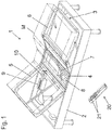
- Fig. 1 shows an exemplary furniture arrangement with a functional furniture 1.
- a bed is shown here as an example.
- the functional furniture 1 has a basic element 2, here a frame-like frame with feet.
- a slatted frame with a functional fitting 3 is inserted into the base element 2.
- the slatted frame carries a mattress M.
- the functional furniture 1 has two movable furniture parts 5 and 6, which can be moved relative to a fixed base part 4 arranged between them.
- the two movable furniture parts 5, 6 are a back part and a leg section.
- back part 5 and leg part 6 are also referred to below as back part 5 and leg part 6.
- the movable arrangement of the movable furniture parts 5 and 6 is realized by the functional fitting 3, also called a movement fitting.
- the movement is displaceable and / or pivotable.
- the movably mounted back part 5 and the leg part 6 are each coupled to an electromotive adjustment drive 7, 8.
- the back part 5 is coupled to the electromotive adjustment drive 7.
- the electromotive adjusting drive 8 is provided for moving or adjusting the leg part 6.
- the electromotive adjustment drives 7, 8 are designed here as linear drives.
- the linear drives have one or a number of electric motors, each motor being followed by a speed reduction gear with at least one gear stage.
- the speed reduction gear can be followed by a further gear, for example in the form of a threaded spindle gear, which generates a linear movement of the output member from the rotational movement of the motor.
- the last transmission link or a further link connected to it forms an output link.
- the output member of the respective electromotive adjustment drive is connected to the respective furniture component (back part 5, leg part 6) or alternatively to a component connected to the base frame 2, so that when the electric motor of the respective adjustment drive 7, 8 is in operation, the movable furniture components are adjusted relative to one another will.
- the electromotive adjustment drives 7, 8 are connected to a control device 9.
- This connection can be made, for example, as a pluggable cable connection, which is not shown here.
- the control device 9 has an electrical supply unit, which provides the electrical energy, for example from the network, for the electromotive adjusting drives 7, 8.
- the control device 9 in this example can be connected to a power connector with a power connector via a power cord (not shown).
- the mains plug leads the mains voltage on the input side to the electrical supply unit the control device 9, which emits a low voltage in the form of a DC voltage on the secondary side and forwards it to a motor controller.
- control device 9 is connected upstream of a line-dependent voltage supply, also not shown, with a mains input and with a secondary-side low-voltage output, which supplies the low-voltage in the form of a DC voltage via a line.
- An operating unit 20 is also assigned to the furniture 1, with its operating elements 21 the electromechanical adjusting drives 7, 8 can be controlled via the control device 9.
- a control signal for controlling the respective electromechanical adjustment drive 7, 8 is transmitted to the control device 9 wirelessly or by wire via a transmission link.
- the control device 9 has switching elements which convert the control signals of the transmission link into switching signals for switching the respective adjustment drive 7, 8.
- the switching elements can e.g. Relay switch and / or semiconductor switch.
- the manually operable control elements 21 of the control unit 20 generate control signals which are converted by the receiver of the control device 9 into control currents for the switching elements.
- the control elements 21 switch the control current of the relay switches or the semiconductor switches.
- the circuit breakers of the relay switches or the semiconductor switches switch the high motor current of the respective electromotive adjusting drive 7, 8.
- the functional furniture 1 shown is equipped according to the application with proximity and / or touch detectors which prevent actuation of the adjusting devices 7, 8 via the control device 9 when approaching one Sensor or a touch of the sensor is detected. This is discussed below in connection with Fig. 2 explained in more detail.
- Fig. 2 shows the system of Fig. 1 in a schematic block diagram.
- the same reference numerals in this figure denote the same or equivalent elements as in Fig. 1 .
- the furniture fitting has the two movable furniture parts, the back part 5 and the leg part 6, which are movable relative to a fixed base part 4.
- the movement is achieved via the two electromotive adjusting drives 7, 8, which act on the back part 5 and the leg part 6.
- the mechanical coupling of the adjustment drives 7, 8 on the back or leg part 5, 6 is with the Fig. 2 symbolized only by a dashed line.
- the adjustment drives 7, 8 are controlled by the control device 9 and supplied with current.
- a power supply to the control device 9, for example via an integrated or external power supply unit, is shown in FIG Fig. 2 not shown.
- an evaluation circuit 10 is provided which contacts one of the movable furniture parts 5, 6 detected.
- the evaluation circuit 10 is arranged externally by the control device 9 and is electrically connected to it via an output 13 of the evaluation circuit 10.
- the evaluation circuit 10 can be integrated in the housing of the control device 9.
- the evaluation circuit 10 has two inputs 11, 12 which are coupled to the furniture parts 5, 6 via sensor lines 111, 121.
- two sensor groups are formed, each of which comprises the sensor line 111 or 121 and the furniture part 5, 6.
- two independent contact and / or proximity detectors are formed as anti-trap protection.
- Touching or approaching the furniture parts 5, 6 is detected by the evaluation circuit 10 via the sensor lines 111, 121.
- a signal is generated at an output 13 of the evaluation circuit 10, which causes the control device 9 to stop at least one of the two adjustment drives 7, 8.
- a touch of the furniture part 5 or approach to the furniture part 5 detected via the sensor line 111 only stops the assigned adjustment drive 7, whereas the detection of a touch of the furniture part 6 or approach to the furniture part 6 via the sensor line 121 the assigned one Adjustment drive 8 stops.
- each touch regardless of which sensor line 111, 121 or which of the inputs 11, 12 of the evaluation circuit 10 detects, leads to a stopping of any adjustment drives 7, 8 which may be actuated simultaneously.
- the adjustment drives 7, 8 are not only stopped, but that a moving adjustment drive 7, 8 is operated in the reverse direction of movement for a predetermined short period after stopping, in order to release a body part that may already be jammed .
- the detection of touching of the sensors by the evaluation circuit 10 is preferably capacitive.
- This capacitive contact or proximity detection can be set so sensitively that no direct galvanic contact of an input 11 or an exposed section of the sensor line 111, 121 is required, but rather a contact or approach to insulated sections of the sensor line 111 or with it coupled furniture parts 5, 6 or sections of a functional fitting also coupled therewith can be detected. In this way, detection of contact with a painted or plastic-coated area of the movable furniture parts 5, 6 is made possible.
- a conductive element can be applied.
- the conductive element can consist in the continuation of the sensor line 111, 121 itself.
- metallized foils can, for example, be glued to the non-conductive material.
- an insulating material with a conductive coating for example based on a conductive polymer, superficially conductive. Fabrics or Yarns with woven metallic threads or fibers can be used as conductive elements.
- the sensor line 111 makes direct contact with the furniture part 5 in a conductive connection 112. If the furniture part 5 is a painted steel tube, the paint can be removed at one point, for example, and the sensor line 111 can be attached at this point. Alternatively, for example, a self-tapping screw can be screwed into the metal tube of the furniture part 5, via which the conductive connection 112 takes place.
- the sensor line 121 is coupled to the furniture part 6 via a capacitive coupling 122.
- the sensor line 121 has a flat electrode at its end, which is glued to a painted area of the furniture part 6, for example by means of a self-adhesive layer. The change in capacitance of the furniture part 6 by approaching or touching a body part is transmitted through this capacitive coupling 122 to the sensor line 121 and thus to the evaluation circuit 10.
- two inputs 11, 12 and two corresponding sensor lines 111, 121 are provided by way of example. It is understood that this number is purely exemplary. It is also possible to provide more than the two sensor lines 111, 121 shown, by means of which more than two groups of monitored movable furniture parts 5, 6 on the functional furniture 1 are defined.
- the design of the various detectors makes it possible to reliably monitor even a large functional fitting, such as, for example, in the bed shown as functional furniture 1, without having to ensure that furniture parts 5, 6 to be monitored are galvanically connected to one another or that they are sufficient capacitive coupling of the furniture parts to one another is given.
- the division of the movable furniture parts 5, 6 to be monitored overall in a functional piece of furniture for an anti-trap protection into at least two Groups that are assigned to different detectors also prevent an undesirable false response due to interference radiation, which, if the sensor area is otherwise too large, can be coupled in more easily.
- the evaluation circuit 10 can internally have a single detector circuit for the change in capacitance, which is connected in a multiplex process to the at least two inputs 11, 12 in rapid alternation (sequential evaluation). This measure of dividing into several groups and the sequential evaluation with only one detector circuit enables inexpensive production and easy assembly of a highly sensitive pinch protection with high operational reliability at the same time.
- the evaluation circuit 10 can have a number of detector circuits for a change in capacitance corresponding to the number of inputs 11, which are coupled to one another on the output side via a corresponding logic circuit, for example a "or" link, so that when each of the detector circuits responds, a corresponding output signal at the output 13 is output.
- a larger number of inputs 11, 12 can be provided, for example four inputs 11, 12, which also offers a sufficient number of groups for larger functional fittings.
- inputs 11, 12 which are not used can be set inactive, for example by connection to a ground potential.
- individual inputs 11, 12 can be selectively deactivated by parameterizing a multiplexer used on the input side or a logic used on the output side in the evaluation circuit 10.
- the detector circuits for detecting a change in capacitance are preferably self-adjusting, so that a slow change in capacitance, which is caused, for example, by changing environmental conditions such as changing air humidity, does not lead to false triggering.
- the sensor lines 111, 121 are prefers ordinary single-core cables without shielding, which are inexpensive and can be easily laid.
- one evaluation circuit each can be assigned to one control device.
Landscapes
- Health & Medical Sciences (AREA)
- Nursing (AREA)
- General Health & Medical Sciences (AREA)
- Life Sciences & Earth Sciences (AREA)
- Animal Behavior & Ethology (AREA)
- Public Health (AREA)
- Veterinary Medicine (AREA)
- Power-Operated Mechanisms For Wings (AREA)
- Elimination Of Static Electricity (AREA)
Abstract
Die Erfindung betrifft einen elektromotorischen Möbelantrieb zur Verstellung von bewegbaren Möbelteilen (5, 6) eines Funktionsmöbels (1), aufweisend eine Steuerungseinrichtung (9), wenigstens einen Verstellantrieb (7, 8) mit einem Elektromotor und wenigstens eine Auswerteschaltung (10) mit einem Eingang (11, 12), welche zusammen mit einem an dem Funktionsmöbel (1) angebrachten Sensor elektrisch leitend verbindbar ist und einen Annäherungs- und/oder Berührungsdetektor bildet. Der elektromotorische Möbelantrieb zeichnet sich dadurch aus, dass durch jeweils einen Sensor oder eine Gruppe von Sensoren mit der wenigstens einen Auswerteschaltung (10) mindestens zwei Annäherungs- und/oder Berührungsdetektoren gebildet sind, die unterschiedlichen beweglichen Möbelteilen (5, 6) des Funktionsmöbels (1) zuweisbar sind. Dabei ist eine Auswerteschaltung (10) mit mindestens zwei Eingängen (11, 12) vorhanden ist, wobei jeder der Eingänge (11, 12) mit einem Sensor oder einer Gruppe von Sensoren gekoppelt ist, und wobei die Auswerteschaltung (10) einen Multiplexer aufweist, über den die mindestens zwei Eingänge (11, 12) sequenziell mit einer Detektorschaltung der Auswerteschaltung (10) verbindbar sind. Die Erfindung betrifft weiterhin ein Funktionsmöbel (1) mit wenigstens zwei Gruppen von bewegbaren Möbelteilen (5, 6) und einem derartigen elektromotorischen Möbelantrieb.The invention relates to an electromotive furniture drive for adjusting movable furniture parts (5, 6) of a functional piece of furniture (1), comprising a control device (9), at least one adjustment drive (7, 8) with an electric motor and at least one evaluation circuit (10) with an input (11, 12), which can be connected in an electrically conductive manner together with a sensor attached to the functional furniture (1) and forms a proximity and / or touch detector. The electromotive furniture drive is characterized in that at least two proximity and / or contact detectors are formed by a sensor or a group of sensors with the at least one evaluation circuit (10), the different movable furniture parts (5, 6) of the functional furniture (1 ) are assignable. There is an evaluation circuit (10) with at least two inputs (11, 12), each of the inputs (11, 12) being coupled to a sensor or a group of sensors, and the evaluation circuit (10) having a multiplexer, Via which the at least two inputs (11, 12) can be connected sequentially to a detector circuit of the evaluation circuit (10). The invention further relates to functional furniture (1) with at least two groups of movable furniture parts (5, 6) and such an electromotive furniture drive.
Description
Die Erfindung betrifft einen elektromotorischen Möbelantrieb zur Verstellung von bewegbaren Möbelteilen eines Funktionsmöbels, aufweisend eine Steuerungseinrichtung, wenigstens einen Verstellantrieb mit einem Elektromotor und wenigstens eine Auswerteschaltung mit einem Eingang, welche zusammen mit einem an dem Funktionsmöbel angebrachten Sensor elektrisch leitend verbindbar ist und einen Annäherungs- und/oder Berührungsdetektor bildet. Die Erfindung bezieht sich zudem auf ein Funktionsmöbel mit einem solchen elektromotorischen Möbelantrieb.The invention relates to an electromotive furniture drive for adjusting movable furniture parts of a functional piece of furniture, comprising a control device, at least one adjusting drive with an electric motor and at least one evaluation circuit with an input, which can be electrically conductively connected together with a sensor attached to the functional piece of furniture and an approximation and / or forms a touch detector. The invention also relates to functional furniture with such an electromotive furniture drive.
Derartige elektromotorische Möbelantriebe sind bekannt und umfassen beispielsweise eine Anzahl Verstellantriebe, beispielsweise Linearantriebe. Ein Linearantrieb erzeugt eine Linearbewegung an einem Abtriebsglied und weist wenigstens einen Elektromotor, einen Getriebezug und das Abtriebsglied auf, wobei dem Elektromotor der Getriebezug mit dem Abtriebsglied nachgeschaltet ist. Der Linearantrieb und dessen Abtriebsglied sind mit Möbelbauteilen verbunden und bewegen bzw. verstellen diese bei Betrieb der Motoren relativ zueinander. Die Möbelbauteile sind z.B. mit einem Grundgestell und/oder untereinander durch sogenannte Funktions- oder Bewegungsbeschläge beweglich verbunden. Diese Beschläge sind üblicherweise aus metallischen Werkstoffen, wie z.B. Stahl.Electromotive furniture drives of this type are known and include, for example, a number of adjustment drives, for example linear drives. A linear drive generates a linear movement on a driven member and has at least one electric motor, a gear train and the driven member, the gear train with the driven member being connected downstream of the electric motor. The linear drive and its output member are connected to furniture components and move or adjust them relative to one another when the motors are operating. The furniture components are e.g. movably connected to a base frame and / or to one another by so-called functional or movement fittings. These fittings are usually made of metallic materials, such as Stole.
Ein Funktionsmöbel ist mit mindestens einem elektromotorischen Möbelantrieb versehen. Ein solcher elektromotorischer Möbelantrieb ist in dem Möbel angebracht, welches feste und bewegliche Möbelbauteile aufweist. Feste Möbelbauteile sind z.B. Rahmenbauelemente. Bewegliche Möbelbauteile sind z.B. feste oder federnachgiebige Stützflächen einer Polsterung oder einer Matratze des Sitz- und/oder Liegemöbels sowie manuell oder elektromotorisch verstellbare Abschnitte oder Elemente des Möbels.A functional piece of furniture is provided with at least one electromotive furniture drive. Such an electromotive furniture drive is mounted in the furniture, which has fixed and movable furniture components. Fixed furniture components are e.g. Frame components. Movable furniture components are e.g. firm or resilient support surfaces of an upholstery or mattress of the seating and / or reclining furniture as well as sections or elements of the furniture that can be adjusted manually or by an electric motor.
Der elektromotorische Möbelantrieb dient zur Verstellung der bewegbaren Möbelbauteile. Dabei wird die von dem elektromotorischen Möbelantrieb erzeugte Verstellbewegung und Antriebskraft auf das jeweilige bewegbare Möbelbauteil übertragen, wobei sich der elektromotorische Möbelantrieb an einem festen Möbelbauteil abstützt und das bewegbare Möbelbauteil relativ zu dem festen Möbelbauteil verstellt. Der elektromotorische Möbelantrieb kann auch zwischen zwei bewegbaren Möbelbauteilen angebracht sein, wobei er diese relativ zueinander verstellen kann.The electromotive furniture drive is used to adjust the movable furniture components. The adjustment movement and driving force generated by the electromotive furniture drive is transmitted to the respective movable furniture component, wherein the electromotive furniture drive is supported on a fixed furniture component and the movable furniture component is adjusted relative to the fixed furniture component. The electromotive furniture drive can also be attached between two movable furniture components, whereby it can be adjusted relative to one another.
Elektromotorische Möbelantriebe sind aus dem Stand der Technik in einer Vielzahl von unterschiedlichen Ausführungen für unterschiedliche Einsatzfälle und Zwecke bekannt, z.B. als Einzelantriebe, Doppel- und Mehrfachantriebe.Electromotive furniture drives are known from the prior art in a variety of different designs for different applications and purposes, e.g. as single drives, double and multiple drives.
Steuerungseinrichtungen sind ebenfalls bekannt, welche dazu ausgebildet sind, den jeweiligen Elektromotor eines Verstellantriebs auf Befehl oder in Folge eines Ereignisses, z.B. ein Steuerbefehl einer Handbedienung, eines Endschalters, eines Detektors usw., anzusteuern. Die Steuerungseinrichtungen verfügen über Ein- und Ausgänge. Die Ausgänge sind beispielsweise mit dem jeweiligen Elektromotor elektrisch leitend verbunden. Die Eingänge sind beispielsweise mit Handfernbedienungen oder, ggf. über Auswerteschaltungen, mit Sensoren und Detektoren elektrisch leitend verbunden. Andere Steuerungseinrichtungen weisen andere Ausgänge auf, welche ausschließlich ein elektrisches oder ein elektromechanisches Signal zu einer weiteren Steuerungseinrichtung leiten, welche die zuvor beschriebenen Ausgänge zum Betrieb des jeweiligen Elektromotors aufweisen.Control devices are also known, which are designed to control the respective electric motor of an adjustment drive on command or as a result of an event, e.g. to control a control command of a manual control, a limit switch, a detector, etc. The control devices have inputs and outputs. The outputs are electrically conductively connected to the respective electric motor, for example. The inputs are connected, for example, to manual remote controls or, if necessary via evaluation circuits, to sensors and detectors in an electrically conductive manner. Other control devices have other outputs which exclusively transmit an electrical or an electromechanical signal to a further control device which have the previously described outputs for operating the respective electric motor.
Insbesondere die eingangs beschriebenen Steuerungseinrichtungen haben sich bewährt. Aus der Druckschrift
Unter dem Begriff "Funktionsbeschlag" sind dabei auch metallische Gestelle und Teile, wie z.B. Füße, eines Funktionsmöbels zu verstehen. Der Begriff "Sensor" bedeutet hier ein Element eines Funktionsbeschlages oder ein separates, elektrisch leitendes Element, wie z.B. ein Kabel, Stabantenne, Flacheisen usw., welches sich am Möbel angebracht ist.The term "functional fitting" also includes metallic frames and parts, such as Feet to understand functional furniture. The term "sensor" here means an element of a functional fitting or a separate, electrically conductive element, such as e.g. a cable, rod antenna, flat iron, etc., which is attached to the furniture.
Die eingangs genannte Steuerungseinrichtung hat sich bestens bewährt. Ein Nachteil besteht jedoch bei großen Möbelstücken, wie bei breiten Betten oder bei komplexen Möbelstücken, wie bei einer Aufteilung der Funktionsbeschläge in mehrere Gruppen.The control device mentioned at the outset has proven its worth. However, there is a disadvantage with large pieces of furniture, such as with wide beds or with complex pieces of furniture, such as when the functional fittings are divided into several groups.
Mehrere Gruppen können gebildet sein, wenn beispielsweise bei einem Bett ein Obergestell über elektrisch isolierenden Rollen oder Gleitern mit einem Untergestell verbunden sind. Eine weitere Gruppe kann gebildet sein, wenn ein Fußklappenbeschlagsabschnitt eines Funktionsbeschlags eines Sessels mit Kunststofflagern elektrisch isoliert von dem Grundgestell angeordnet ist. Andere Gruppen können gebildet sein, wenn das Möbel mehrere Funktionsbeschläge aufweist, welche jeweils für Teilbereiche des Möbels Verwendung finden.Several groups can be formed if, for example, in a bed an upper frame is connected to a lower frame via electrically insulating rollers or sliders. A further group can be formed if a foot flap fitting section of a functional fitting of an armchair with plastic bearings is arranged in an electrically insulated manner from the base frame. Other groups can be formed if the piece of furniture has a plurality of functional fittings, which are each used for partial areas of the piece of furniture.
Um einen Einklemmschutz für alle bewegbaren Möbelteile zu schaffen, müssen gemäß dem Stand der Technik alle bewegbaren Möbelteile bzw. alle Abschnitte aller Funktionsbeschläge des Möbels über flexible Leitungen elektrisch miteinander verbunden werden. Diese Methode hat sich zwar ebenfalls bewährt, jedoch ist der Aufwand der Steuerungseinrichtung sehr hoch, was sich in der Hochwertigkeit und in dem Montageaufwand der elektrischen Messschaltung widerspiegelt. Ferner hat sich heraus gestellt, dass ein komplexer Abgleich des Systems erforderlich ist, um Fehlauslösungen des Einklemmschutzes zu verhindern.In order to provide protection against trapping for all movable furniture parts, according to the prior art, all movable furniture parts or all sections of all functional fittings of the furniture must be electrically connected to one another via flexible lines. Although this method has also proven itself, the effort of the control device is very high, which is reflected in the high quality and the assembly effort of the electrical measuring circuit. It has also turned out that a complex adjustment of the system is necessary to prevent false triggering of the pinch protection.
Der Erfindung liegt die Aufgabe zu Grunde, einen elektromotorischen Möbelantrieb mit einer Steuerungseinrichtung der eingangs genannten Art bereitzustellen, wobei die beschriebenen Nachteile nicht mehr auftreten oder in bedeutender Weise reduziert sind, und der darüber hinaus leicht zu montieren ist und leicht in der Handhabung ausgebildet ist.The invention is based on the object of providing an electromotive furniture drive with a control device of the type mentioned, the disadvantages described no longer occurring or being reduced significantly, and which is also easy to assemble and is easy to handle.
Die Lösung der Aufgabenstellung erfolgt durch die Anordnung von mehr als einem Annäherungs- und/oder Berührungsdetektor an einem Funktionsmöbel. Dabei bildet jeweils ein Sensor oder eine Gruppe von Sensoren mit einer Auswerteschaltung einen solchen Detektor, wobei jeder Sensor oder jede Gruppe von Sensoren mit einem Eingang der Auswerteschaltung verbunden ist. In erfinderischer Weise weist dabei das Möbel eine Mehrzahl Detektoren auf, welche einzeln mit einem Eingang der Auswerteschaltung der Steuerungseinrichtung elektrisch leitend verbunden sind.The task is solved by arranging more than one proximity and / or touch detector on a functional piece of furniture. A sensor or a group of sensors with an evaluation circuit forms such a detector, each sensor or group of sensors being connected to an input of the evaluation circuit. In an inventive manner, the piece of furniture has a plurality of detectors, which are individually connected in an electrically conductive manner to an input of the evaluation circuit of the control device.
Die Ausbildung der verschiedenen Detektoren ermöglicht es, auch einen großen Funktionsbeschlag, wie beispielsweise bei dem dargestellten Bett als Funktionsmöbel sicher zu überwachen, ohne dass dafür Sorge getragen werden muss, dass zu überwachende Möbelteile untereinander galvanisch miteinander verbunden sind oder dass eine ausreichende kapazitive Kopplung der Möbelteile untereinander gegeben ist. Die Aufteilung der insgesamt bei einem Funktionsmöbel für einen Einklemmschutz zu überwachenden bewegbaren Möbelteilen in mindestens zwei Gruppen, die verschiedenen Detektoren zugewiesen sind, verhindert zudem ein unerwünschtes Fehlansprechen durch Störstrahlungen, die bei einer andernfalls unter Umständen zu großen Sensorfläche leichter einkoppeln können.The design of the various detectors makes it possible to reliably monitor even a large functional fitting, such as the bed shown as functional furniture, without having to ensure that furniture parts to be monitored are galvanically connected to one another or that there is sufficient capacitive coupling of the furniture parts is given among themselves. The division of the movable furniture parts to be monitored in a functional piece of furniture for anti-trap protection into at least two groups, which are assigned to different detectors, also prevents an undesirable false response due to interference radiation, which can otherwise be coupled in more easily if the sensor surface is otherwise too large.
Dabei weist die Steuerungseinrichtung eine Auswerteschaltung mit einer Mehrzahl von mindestens zwei Eingänge auf, wobei jeder Eingang mit einem Sensor oder einer Gruppe von Sensoren gekoppelt ist. Zudem weist die Auswerteschaltung einen Multiplexer auf, über den die mindestens zwei Eingänge sequenziell mit einer Detektorschaltung der Auswerteschaltung verbindbar sind. Durch diese Maßnahme des Einteilens in mehrere Gruppen verbunden mit einer sequenziellen Auswertung mit nur einer Detektorschaltung ist die preiswerte Herstellung und leichte Montage eines hochempfindlichen Einklemmschutzes bei gleichzeitig hoher Betriebszuverlässigkeit möglich.The control device has an evaluation circuit with a plurality of at least two inputs, each input being coupled to a sensor or a group of sensors. In addition, the evaluation circuit has a multiplexer, via which the at least two inputs can be connected sequentially to a detector circuit of the evaluation circuit. This measure of dividing into several groups combined with a sequential evaluation using only one detector circuit enables inexpensive production and easy assembly of a highly sensitive pinch protection with high operational reliability at the same time.
In einer vorteilhaften Ausgestaltung des elektromotorischen Möbelantriebs sind der Sensor oder die Gruppe von Sensoren mit einem der Eingänge der wenigstens einen Auswerteschaltung leitfähig verbunden. Alternativ sind der Sensor oder die Gruppe von Sensoren kapazitiv mit einem der Eingänge der wenigstens einen Auswerteschaltung gekoppelt.In an advantageous embodiment of the electromotive furniture drive, the sensor or the group of sensors is conductively connected to one of the inputs of the at least one evaluation circuit. Alternatively, the sensor or the group of sensors is capacitively coupled to one of the inputs of the at least one evaluation circuit.
In einer weiteren vorteilhaften Ausgestaltung des elektromotorischen Möbelantriebs ist der Sensor eine Sensorleitung und/oder ein leitfähiges bewegbares Möbelteil und/oder ein leitfähiges Element eines Funktionsbeschlags.In a further advantageous embodiment of the electromotive furniture drive, the sensor is a sensor line and / or a conductive movable furniture part and / or a conductive element of a functional fitting.
Ein erfindungsgemäßes Funktionsmöbel weist wenigstens zwei Gruppen von bewegbaren Möbelteilen auf und zumindest einen elektromotorischen Möbelantrieb nach einem der vorhergehenden Ansprüche. Es ergeben sich die im Zusammenhang mit dem Möbelantrieb zuvor genannten Vorteile.A functional furniture according to the invention has at least two groups of movable furniture parts and at least one electromotive furniture drive according to one of the preceding claims. The advantages mentioned above in connection with the furniture drive result.
Die Erfindung wird nachfolgend anhand eines Ausführungsbeispiels mithilfe von Figuren näher erläutert. Es zeigen:
- Fig. 1
- eine schematische Perspektivansicht einer beispielhaften Möbelanordnung; und
- Fig. 2
- ein Blockschaltbild der von Komponenten der Möbelanordnung.
- Fig. 1
- a schematic perspective view of an exemplary furniture arrangement; and
- Fig. 2
- a block diagram of the components of the furniture arrangement.
Das Funktionsmöbel 1 weist in dem dargestellten Beispiel zwei bewegbare Möbelteile 5 und 6 auf, welche relativ zu einem zwischen ihnen angeordneten festen Grundteil 4 bewegbar sind. Konkret sind die beiden bewegbare Möbelteile 5, 6 ein Rückenteil und ein Beinteil. Sie werden nachfolgend der einfacheren Darstellung halber auch als Rückenteil 5 und Beinteil 6 bezeichnet.In the example shown, the functional furniture 1 has two
Die bewegliche Anordnung der bewegbaren Möbelteile 5 und 6 wird durch den Funktionsbeschlag 3, auch Bewegungsbeschlag genannt, realisiert. Die Bewegung ist verschiebbar und/oder schwenkbar ausgebildet.The movable arrangement of the
Das beweglich gelagerte Rückenteil 5 und das Beinteil 6 sind jeweils mit einem elektromotorischen Verstellantrieb 7, 8 gekoppelt. So ist das Rückenteil 5 mit dem elektromotorischen Verstellantrieb 7 gekoppelt. Zur Bewegung bzw. Verstellung des Beinteils 6 ist der elektromotorische Verstellantrieb 8 vorgesehen.The movably mounted back
Die elektromotorischen Verstellantriebe 7, 8 sind hier als Linearantriebe ausgebildet. Die Linearantriebe weisen einen oder eine Anzahl Elektromotore auf, wobei jedem Motor ein Drehzahlreduziergetriebe mit wenigstens einer Getriebestufe nachgeschaltet ist. Dem Drehzahlreduziergetriebe kann ein weiteres Getriebe, beispielsweise in Form eines Gewindespindelgetriebes, nachgeschaltet sein, welches aus der Drehbewegung des Motors eine Linearbewegung des Abtriebsgliedes erzeugt. Das letzte Getriebeglied oder ein damit verbundenes weiteres Glied bildet ein Abtriebsglied. Das Abtriebsglied des jeweiligen elektromotorischen Verstellantriebs steht mit dem jeweiligen Möbelbauteil (Rückenteil 5, Beinteil 6) oder alternativ mit einem mit dem Grundrahmen 2 verbundenem Bauteil in Verbindung, so dass bei einem Betrieb des Elektromotors des jeweiligen Verstellantriebs 7, 8 die beweglichen Möbelbauteile relativ zueinander verstellt werden.The electromotive adjustment drives 7, 8 are designed here as linear drives. The linear drives have one or a number of electric motors, each motor being followed by a speed reduction gear with at least one gear stage. The speed reduction gear can be followed by a further gear, for example in the form of a threaded spindle gear, which generates a linear movement of the output member from the rotational movement of the motor. The last transmission link or a further link connected to it forms an output link. The output member of the respective electromotive adjustment drive is connected to the respective furniture component (back
Die elektromotorischen Verstellantriebe 7, 8 sind mit einer Steuerungseinrichtung 9 verbunden. Diese Verbindung kann z.B. als steckbare Kabelverbindung ausgeführt sein, was hier nicht näher dargestellt ist. Die Steuerungseinrichtung 9 weist eine elektrische Versorgungseinheit auf, welche die elektrische Energie, z.B. aus dem Netz, für die elektromotorischen Verstellantriebe 7, 8 bereitstellt. Dazu ist die Steuerungseinrichtung 9 in diesem Beispiel über ein nicht gezeigtes Netzkabel mit einem Netzstecker mit einem Netzanschluss verbindbar. Der Netzstecker leitet über das Netzkabel die eingangsseitige Netzspannung zu der elektrischen Versorgungseinheit der Steuerungseinrichtung 9, welche sekundärseitig eine Kleinspannung in Form einer Gleichspannung abgibt und diese zu einer Motorsteuerung weiterleitet.The electromotive adjustment drives 7, 8 are connected to a
Alternativ hierzu ist der Steuerungseinrichtung 9 eine ebenfalls nicht näher dargestellte netzabhängige Spannungsversorgung mit Netzeingang und mit sekundärseitigem Kleinspannungsausgang vorgeschaltet, welche über eine Leitung die Kleinspannung in Form einer Gleichspannung zuführt.As an alternative to this, the
Dem Möbel 1 ist ferner eine Bedieneinheit 20 zugewiesen, mit dessen Bedienelementen 21 die elektromechanischen Verstellantriebe 7, 8 über die Steuerungseinrichtung 9 steuerbar sind. Bei Betätigen eines Bedienelementes 21 wird ein Steuersignal zur Ansteuerung des jeweiligen elektromechanischen Verstellantriebs 7, 8 über eine Übertragungsstrecke drahtlos oder drahtgebunden der Steuerungseinrichtung 9 übermittelt.An operating
Die Steuerungseinrichtung 9 weist Schaltelemente auf, welche die Steuersignale der Übertragungsstrecke in Schaltsignale zum Schalten des jeweiligen Verstellantriebs 7, 8 umwandeln. Die Schaltelemente können z.B. Relaisschalter oder/und Halbleiterschalter sein. Die manuell betätigbaren Bedienelemente 21 der Bedieneinheit 20 erzeugen Steuersignale, die vom Empfänger der Steuerungseinrichtung 9 in Steuerströme für die Schaltelemente umgewandelt werden. Bei einer drahtgebundenen Bedieneinheit 20 schalten die Bedienelemente 21 den Steuerstrom der Relaisschalter bzw. der Halbleiterschalter. In beiden Fällen schalten die Leistungsschalter der Relaisschalter bzw. der Halbleiterschalter den hohen Motorstrom des jeweiligen elektromotorischen Verstellantriebs 7, 8.The
Um ein Einklemmen eines Körperteils bei Bewegen der bewegbaren Möbelteile 5, 6 zu verhindern, ist das dargestellte Funktionsmöbel 1 anmeldungsgemäß mit Annäherungs- und/oder Berührungsdetektoren ausgestattet, die eine Betätigung der Verstelleinrichtungen 7, 8 über die Steuerungseinrichtung 9 verhindern, wenn eine Annäherung an einen Sensor bzw. eine Berührung des Sensors detektiert wird. Dieses wird nachfolgend im Zusammenhang mit
Wie im Zusammenhang mit
Um zu verhindern, dass ein Körperteil beim Bewegen einer der bewegbaren Möbelteile 5, 6 beispielsweise zwischen dem bewegbaren Möbelteil 5, 6 und einem feststehenden Teil des Funktionsmöbels 1 eingeklemmt wird, ist eine Auswerteschaltung 10 vorgesehen, die eine Berührung eines der bewegbaren Möbelteile 5, 6 detektiert. Die Auswerteschaltung 10 ist im dargestellten Beispiel extern von der Steuerungseinrichtung 9 angeordnet und mit dieser über einen Ausgang 13 der Auswerteschaltung 10 elektrisch verbunden. In alternativen Ausgestaltungen kann die Auswerteschaltung 10 in das Gehäuse der Steuerungseinrichtung 9 integriert sein.In order to prevent a body part from being pinched when moving one of the
Die Auswerteschaltung 10 weist im dargestellten Beispiel zwei Eingänge 11, 12 auf, die über Sensorleitungen 111, 121 mit den Möbelteilen 5, 6 gekoppelt sind. Entsprechend sind zwei Sensorgruppen gebildet, die jeweils die Sensorleitung 111 bzw. 121 und das Möbelteil 5, 6 umfassen. Zusammen mit der Auswerteschaltung 10 sind entsprechend zwei unabhängige Berührungs- und/oder Annäherungsdetektoren als Einklemmschutz gebildet.In the example shown, the
Eine Berührung oder Annäherung an die Möbelteile 5, 6 wird über die Sensorleitungen 111, 121 von der Auswerteschaltung 10 detektiert. An einem Ausgang 13 der Auswerteschaltung 10 wird ein Signal generiert, das die Steuerungseinrichtung 9 dazu veranlasst, zumindest einen der beiden Verstellantriebe 7, 8 zu stoppen. Dabei kann vorgesehen sein, dass eine über die Sensorleitung 111 detektierte Berührung des Möbelteils 5 bzw. Annäherung an das Möbelteil 5 nur den zugeordneten Verstellantrieb 7 stoppt, wohingegen die Detektion einer Berührung des Möbelteils 6 bzw. Annäherung an das Möbelteil 6 über die Sensorleitung 121 den zugeordneten Verstellantrieb 8 stoppt. Bevorzugt führt jedoch jede Berührung, unabhängig davon, über welche Sensorleitung 111, 121 bzw. welchen der Eingänge 11, 12 der Auswerteschaltung 10 detektiert, zu einem Stoppen aller gegebenenfalls gleichzeitig betätigter Verstellantriebe 7, 8 führt.Touching or approaching the
In einer Weiterbildung kann zudem vorgesehen sein, dass die Verstellantriebe 7, 8 nicht nur gestoppt werden, sondern dass ein bewegter Verstellantrieb 7, 8 für einen vorgegebenen kurzen Zeitraum nach dem Stoppen in die umgekehrte Bewegungsrichtung betrieben wird, um ein möglicherweise bereits eingeklemmtes Körperteil wieder freizugeben.In a further development it can also be provided that the adjustment drives 7, 8 are not only stopped, but that a moving
Die Detektion einer Berührung der Sensoren durch die Auswerteschaltung 10 erfolgt bevorzugt kapazitiv. Diese kapazitive Berührungs- bzw. Annäherungsdetektion kann so empfindlich eingestellt werden, dass keine direkte galvanische Berührung eines Eingangs 11 bzw. eines freigelegten Abschnitts der Sensorleitung 111, 121 erforderlich ist, sondern bereits eine Berührung oder Annäherung an isolierte Abschnitte der Sensorleitung 111 bzw. der damit gekoppelten Möbelteile 5, 6 oder ebenfalls damit gekoppelter Abschnitte eines Funktionsbeschlags detektiert werden können. Auf diese Weise ist eine Detektion einer Berührung auch eines lackierten oder Kunststoff beschichteten Bereichs der bewegbaren Möbelteile 5, 6 ermöglicht.The detection of touching of the sensors by the
Falls zu überwachende bewegte Elemente, beispielsweise die Möbelteile 5, 6 oder andere Abschnitte von Funktionsbeschlägen gänzlich aus einem isolierenden Material, beispielsweise Holz oder Kunststoff gefertigt sind, kann ein leitendes Element aufgebracht werden. Das leitende Element kann in der Weiterführung der Sensorleitung 111, 121 selbst bestehen. Alternativ können beispielsweise metallisierte Folien auf das nichtleitende Material aufgeklebt werden. Weiterhin ist es möglich, ein isolierendes Material mit einer leitenden Lackierung, beispielsweise basierend auf einem leitenden Polymer, oberflächlich leitfähig zu machen. Ebenfalls können Stoffe oder Garne mit eingewebten metallischen Fäden oder Fasern als leitende Elemente eingesetzt werden.If moving elements to be monitored, for example the
In der
Die Sensorleitung 121 ist dagegen über eine kapazitive Kopplung 122 mit dem Möbelteil 6 gekoppelt. Zu diesem Zweck weist die Sensorleitung 121 an ihrem Ende eine flächige Elektrode auf, die beispielsweise mittels einer Selbstklebeschicht auf einen lackierten Bereich des Möbelteils 6 aufgeklebt wird. Die Kapazitätsänderung des Möbelteils 6 durch Annäherung oder Berührung durch ein Körperteil werden durch diese kapazitive Kopplung 122 auf die Sensorleitung 121 und damit die Auswerteschaltung 10 übertragen.In contrast, the
In dem dargestellten Ausführungsbeispiel der
Die Ausbildung der verschiedenen Detektoren ermöglicht es, auch einen großen Funktionsbeschlag, wie beispielsweise bei dem dargestellten Bett als Funktionsmöbel 1 sicher zu überwachen, ohne dass dafür Sorge getragen werden muss, dass zu überwachende Möbelteile 5, 6 untereinander galvanisch miteinander verbunden sind oder dass eine ausreichende kapazitive Kopplung der Möbelteile untereinander gegeben ist. Die Aufteilung der insgesamt bei einem Funktionsmöbel für einen Einklemmschutz zu überwachenden bewegbaren Möbelteilen 5, 6 in mindestens zwei Gruppen, die verschiedenen Detektoren zugewiesen sind, verhindert zudem ein unerwünschtes Fehlansprechen durch Störstrahlungen, die bei einer andernfalls unter Umständen zu großen Sensorfläche leichter einkoppeln können.The design of the various detectors makes it possible to reliably monitor even a large functional fitting, such as, for example, in the bed shown as functional furniture 1, without having to ensure that
Bei der Auswerteschaltung 10 kann intern eine einzelne Detektorschaltung für die Kapazitätsänderung aufweisen, die in einem Multiplexverfahren mit den mindestens zwei Eingängen 11, 12 reihum im schnellen Wechsel verbunden wird (sequenzielle Auswertung). Durch diese Maßnahme des Einteilens in mehrere Gruppen und die sequenzielle Auswertung mit nur einer Detektorschaltung ist die preiswerte Herstellung und leichte Montage eines hochempfindlichen Einklemmschutzes bei gleichzeitig hoher Betriebszuverlässigkeit möglich.In the
Alternativ kann die Auswerteschaltung 10 eine der Anzahl der Eingänge 11 entsprechende Anzahl von Detektorschaltungen für eine Kapazitätsänderung aufweisen, die ausgangsseitig über eine entsprechende Logikschaltung, beispielsweise eine "oder"-Verknüpfung miteinander gekoppelt sind, sodass beim Ansprechen einer jeder der Detektorschaltungen ein entsprechendes Ausgangssignal am Ausgang 13 ausgegeben wird. Um die Auswerteschaltung 10 universell für eine Mehrzahl von Funktionsbeschlägen bzw. Möbeln einsetzen zu können, kann eine größere Anzahl an Eingängen 11, 12 vorgesehen sein, beispielsweise vier Eingänge 11, 12, die auch für größere Funktionsbeschläge eine ausreichende Anzahl an Gruppen bietet.Alternatively, the
Beim Einsatz einer derartigen Auswerteschaltung bei Möbeln, die lediglich zwei oder drei überwachte Gruppen benötigen, können nicht verwendete Eingänge 11, 12 beispielsweise durch Verbindung mit einem Massepotenzial inaktiv gesetzt werden. Alternativ kann durch Parametrisierung eines eingangsseitig verwendeten Multiplexers oder einer ausgangsseitig bei der Auswerteschaltung 10 verwendeten Logik einzelne Eingänge 11, 12 selektiv inaktiv gesetzt werden.When using such an evaluation circuit in furniture which only requires two or three monitored groups,
Die Detektorschaltungen zur Erkennung einer Kapazitätsänderung sind dabei bevorzugt selbstjustierend, sodass eine langsame Kapazitätsänderung, die beispielsweise durch sich ändernde Umweltbedingungen wie sich ändernde Luftfeuchtigkeit hervorgerufen wird, nicht zu einer Fehlauslösung führt. Die Sensorleitungen 111, 121 sind bevorzugt gewöhnliche einadrige Leitungen ohne Abschirmung, die kostengünstig sind und leicht verlegt werden können.The detector circuits for detecting a change in capacitance are preferably self-adjusting, so that a slow change in capacitance, which is caused, for example, by changing environmental conditions such as changing air humidity, does not lead to false triggering. The sensor lines 111, 121 are prefers ordinary single-core cables without shielding, which are inexpensive and can be easily laid.
Wenn an einem Funktionsmöbel mehrere Steuerungseinrichtungen vorgesehen sind, kann je eine Auswerteschaltung einer Steuerungseinrichtung zugeordnet werden.If several control devices are provided on one functional piece of furniture, one evaluation circuit each can be assigned to one control device.
- 11
- FunktionsmöbelFunctional furniture
- 22nd
- GrundelementBasic element
- 33rd
- FunktionsbeschlagFunctional fitting
- 44th
- festes Grundteilfixed base
- 55
- bewegbares Möbelteil (Rückenteil)movable furniture part (back part)
- 66
- bewegbares Möbelteil (Beinteil)movable furniture part (leg part)
- 7, 87, 8
- VerstellantriebAdjustment drive
- 99
- SteuerungseinrichtungControl device
- 1010th
- AuswerteschaltungEvaluation circuit
- 11, 1211, 12
- Eingangentrance
- 111, 121111, 121
- SensorleitungSensor cable
- 112112
- leitende Verbindungconductive connection
- 122122
- kapazitive Kopplungcapacitive coupling
- 1313
- Ausgangexit
- 2020th
- BedieneinheitControl unit
- 2121
- BedienelementControl element
- MM
- Matratzemattress
Claims (8)
dadurch gekennzeichnet, dass
durch jeweils einen Sensor oder eine Gruppe von Sensoren mit der wenigstens einen Auswerteschaltung (10) mindestens zwei Annäherungs- und/oder Berührungsdetektoren gebildet sind, die unterschiedlichen beweglichen Möbelteilen (5, 6) des Funktionsmöbels (1) zuweisbar sind, wobei
eine Auswerteschaltung (10) mit mindestens zwei Eingängen (11, 12) vorhanden ist, wobei jeder der Eingänge (11, 12) mit einem Sensor oder einer Gruppe von Sensoren gekoppelt ist, und wobei
die Auswerteschaltung (10) einen Multiplexer aufweist, über den die mindestens zwei Eingänge (11, 12) sequenziell mit einer Detektorschaltung der Auswerteschaltung (10) verbindbar sind.Electromotive furniture drive for adjusting movable furniture parts (5, 6) of a functional piece of furniture (1), comprising a control device (9), at least one adjustment drive (7, 8) with an electric motor and at least one evaluation circuit (10) with an input (11, 12 ), which can be electrically conductively connected to a sensor attached to the functional furniture (1) and forms a proximity and / or touch detector,
characterized in that
at least two proximity and / or contact detectors are formed by a sensor or a group of sensors with the at least one evaluation circuit (10), which can be assigned to different movable furniture parts (5, 6) of the functional furniture (1), wherein
there is an evaluation circuit (10) with at least two inputs (11, 12), each of the inputs (11, 12) being coupled to a sensor or a group of sensors, and wherein
the evaluation circuit (10) has a multiplexer, via which the at least two inputs (11, 12) can be connected sequentially to a detector circuit of the evaluation circuit (10).
Applications Claiming Priority (3)
| Application Number | Priority Date | Filing Date | Title |
|---|---|---|---|
| DE202014104011 | 2014-08-27 | ||
| PCT/EP2015/069631 WO2016030458A1 (en) | 2014-08-27 | 2015-08-27 | Electromotive furniture drive, and item of functional furniture having an electromotive furniture drive |
| EP15762948.6A EP3185724B1 (en) | 2014-08-27 | 2015-08-27 | Item of functional furniture having an electromotive furniture drive |
Related Parent Applications (1)
| Application Number | Title | Priority Date | Filing Date |
|---|---|---|---|
| EP15762948.6A Division EP3185724B1 (en) | 2014-08-27 | 2015-08-27 | Item of functional furniture having an electromotive furniture drive |
Publications (3)
| Publication Number | Publication Date |
|---|---|
| EP3649896A1 true EP3649896A1 (en) | 2020-05-13 |
| EP3649896B1 EP3649896B1 (en) | 2021-04-07 |
| EP3649896B8 EP3649896B8 (en) | 2021-05-12 |
Family
ID=54105771
Family Applications (2)
| Application Number | Title | Priority Date | Filing Date |
|---|---|---|---|
| EP19218908.2A Active EP3649896B8 (en) | 2014-08-27 | 2015-08-27 | Electro-motoric drive for furniture and piece of furniture having such a drive |
| EP15762948.6A Active EP3185724B1 (en) | 2014-08-27 | 2015-08-27 | Item of functional furniture having an electromotive furniture drive |
Family Applications After (1)
| Application Number | Title | Priority Date | Filing Date |
|---|---|---|---|
| EP15762948.6A Active EP3185724B1 (en) | 2014-08-27 | 2015-08-27 | Item of functional furniture having an electromotive furniture drive |
Country Status (5)
| Country | Link |
|---|---|
| US (1) | US11684163B2 (en) |
| EP (2) | EP3649896B8 (en) |
| CN (1) | CN106793877B (en) |
| DK (2) | DK3649896T3 (en) |
| WO (1) | WO2016030458A1 (en) |
Families Citing this family (4)
| Publication number | Priority date | Publication date | Assignee | Title |
|---|---|---|---|---|
| DE202016105266U1 (en) * | 2016-09-21 | 2017-12-22 | Dewertokin Gmbh | Electromotive furniture drive |
| DE102017131226A1 (en) * | 2017-12-22 | 2019-06-27 | Dewertokin Gmbh | Electromotive furniture drive, furniture and method for detecting a position of an electromotive furniture drive |
| CN111053393A (en) * | 2019-12-17 | 2020-04-24 | 灵璧县德军家具制造有限公司 | Multifunctional deformation bed |
| TWI803397B (en) * | 2022-07-21 | 2023-05-21 | 施權航 | electric bed |
Citations (4)
| Publication number | Priority date | Publication date | Assignee | Title |
|---|---|---|---|---|
| DE9300438U1 (en) * | 1993-01-15 | 1993-03-11 | Dewert Antriebs- und Systemtechnik GmbH & Co. KG, 4983 Kirchlengern | Lifting device |
| DE29707795U1 (en) | 1997-05-02 | 1998-08-27 | Dewert Antriebs- Und Systemtechnik Gmbh & Co. Kg, 32278 Kirchlengern | Adjustment device for movable furniture parts of a piece of furniture |
| US20130174343A1 (en) * | 2012-01-09 | 2013-07-11 | L & P Property Management Company | Capacitive wire sensing for furniture |
| JP2014064883A (en) * | 2011-12-24 | 2014-04-17 | Kazuyoshi Iida | Care bed |
Family Cites Families (38)
| Publication number | Priority date | Publication date | Assignee | Title |
|---|---|---|---|---|
| DE2939942C2 (en) * | 1979-10-02 | 1986-01-09 | FHN-Verbindungstechnik GmbH, 8501 Eckental | Electrical disconnection device, in particular for a window regulator motor of a motor vehicle |
| US4407030A (en) * | 1981-02-09 | 1983-10-04 | Maxwell Products, Inc. | Safety device for an adjustable bed |
| US4977480A (en) * | 1988-09-14 | 1990-12-11 | Fuji Koki Mfg. Co., Ltd. | Variable-capacitance type sensor and variable-capacitance type sensor system using the same |
| US4944056A (en) * | 1988-09-28 | 1990-07-31 | The Research Foundation Of State University Of Ny | Method and apparatus for transporting a disabled person |
| GB2252495B (en) * | 1991-02-06 | 1994-12-14 | Nesbit Evans & Co Ltd | "Adjustable beds" |
| US5235258A (en) * | 1991-03-27 | 1993-08-10 | Santino Antinori | Remotely controlled articulated bed |
| US5235319A (en) * | 1992-05-11 | 1993-08-10 | Joseph C. Hill | Patient monitoring system |
| US5571973A (en) * | 1994-06-06 | 1996-11-05 | Taylot; Geoffrey L. | Multi-directional piezoresistive shear and normal force sensors for hospital mattresses and seat cushions |
| US5796355A (en) * | 1996-05-13 | 1998-08-18 | Zurich Design Laboratories, Inc. | Touch switch |
| DE19814269C2 (en) * | 1998-03-31 | 2001-09-27 | Okin Ges Fuer Antriebstechnik | Security device for furniture |
| IL144231A (en) * | 2001-07-10 | 2006-07-05 | Hollandia The Sleep Engineerin | Control mechanism for adjustable position furniture |
| WO2006116667A2 (en) * | 2005-04-27 | 2006-11-02 | Roho, Inc. | Proximity sensor |
| JP5231222B2 (en) * | 2005-07-08 | 2013-07-10 | ヒル−ロム サービシーズ,インコーポレイティド | Patient support control unit |
| EP2260755B1 (en) * | 2005-11-07 | 2013-12-25 | Stryker Corporation | Patient handling device including normal condition lamp |
| DE202006010135U1 (en) * | 2006-06-28 | 2007-12-27 | Dewert Antriebs- Und Systemtechnik Gmbh | Electromotive furniture drive |
| US20120138067A1 (en) * | 2007-09-14 | 2012-06-07 | Rawls-Meehan Martin B | System and method for mitigating snoring in an adjustable bed |
| US20080255734A1 (en) * | 2007-04-13 | 2008-10-16 | Altshuller Dmitry A | System and method for controlling a vehicle seat |
| CN101917950B (en) * | 2007-10-22 | 2013-09-11 | 马丁·B·罗尔斯-米汉 | Adjustable bed position control |
| EP2255311A2 (en) * | 2008-03-13 | 2010-12-01 | Robert B. Chaffee | Method and apparatus for monitoring and controlling pressure in an inflatable device |
| US8161826B1 (en) * | 2009-03-05 | 2012-04-24 | Stryker Corporation | Elastically stretchable fabric force sensor arrays and methods of making |
| DE202009005020U1 (en) | 2009-07-14 | 2010-12-16 | Dewert Antriebs- Und Systemtechnik Gmbh | First-fail-safe electromotive furniture drive |
| DE102011000602A1 (en) | 2011-02-09 | 2012-08-09 | Dewert Antriebs- Und Systemtechnik Gmbh | Electromotive furniture drive with a power supply device |
| KR101206967B1 (en) * | 2011-04-18 | 2012-11-30 | 주식회사 세라젬 | Thermotherapy Bed |
| DE202011001008U1 (en) | 2011-04-29 | 2012-07-31 | Dewertokin Gmbh | Electromotive furniture drive |
| DE102011050194A1 (en) | 2011-05-06 | 2012-11-08 | Dewert Antriebs- Und Systemtechnik Gmbh | Electromotive furniture drive with a power supply device |
| DE202011051662U1 (en) | 2011-10-18 | 2013-01-21 | Dewert Antriebs-Und Systemtechnik Gmbh | Electromotive furniture drive |
| US9089223B2 (en) * | 2012-01-09 | 2015-07-28 | L&P Property Management Company | Occupancy detection for furniture |
| WO2013127957A1 (en) | 2012-02-28 | 2013-09-06 | Dewertokin Gmbh | Control device for furniture adjusting drives and additional device for a control device |
| WO2013127954A1 (en) | 2012-02-28 | 2013-09-06 | Dewertokin Gmbh | Operating unit control device of a furniture adjusting device |
| EP2819551A1 (en) * | 2012-02-28 | 2015-01-07 | Dewertokin GmbH | Control device for a piece of furniture |
| ES2568922T3 (en) | 2012-02-28 | 2016-05-05 | Dewertokin Gmbh | Furniture arrangement and procedure for the parallel control of two electromotive drives for furniture of a furniture arrangement |
| DK2819552T3 (en) | 2012-02-28 | 2021-04-12 | Dewertokin Tech Group Co Ltd | ELECTROMOTOR FURNITURE DRIVE FOR A FURNITURE, METHOD FOR MONITORING A PULSE WIDTH RATIO FOR AN ELECTRO MOTOR FURNITURE DRIVE, AND A CORRESPONDING FURNITURE |
| CN104271002B (en) | 2012-02-28 | 2018-01-16 | 德沃特奥金有限公司 | For the emergency power supply unit of the electric furniture driver of furniture, electric furniture driver and corresponding furniture |
| DE102012105227A1 (en) | 2012-06-15 | 2013-12-19 | Dewertokin Gmbh | Electromotive furniture drive assembly |
| US20140094997A1 (en) * | 2012-09-28 | 2014-04-03 | Elwha Llc | Automated Systems, Devices, and Methods for Transporting and Supporting Patients Including Multi-Floor Operation |
| WO2017084984A1 (en) * | 2015-11-16 | 2017-05-26 | Dewertokin Gmbh | Electric motor-driven furniture drive, furniture and methods for controlling an electric motor-driven furniture drive |
| DE102016109524A1 (en) * | 2015-12-30 | 2017-07-06 | Dewertokin Gmbh | Sleeping or rest furniture and electromotive furniture drive for such furniture and method for providing an information and / or warning signal by an electromotive furniture drive |
| DE102017131226A1 (en) * | 2017-12-22 | 2019-06-27 | Dewertokin Gmbh | Electromotive furniture drive, furniture and method for detecting a position of an electromotive furniture drive |
-
2015
- 2015-08-27 DK DK19218908.2T patent/DK3649896T3/en active
- 2015-08-27 US US15/506,569 patent/US11684163B2/en active Active
- 2015-08-27 CN CN201580046032.8A patent/CN106793877B/en active Active
- 2015-08-27 DK DK15762948.6T patent/DK3185724T3/en active
- 2015-08-27 EP EP19218908.2A patent/EP3649896B8/en active Active
- 2015-08-27 EP EP15762948.6A patent/EP3185724B1/en active Active
- 2015-08-27 WO PCT/EP2015/069631 patent/WO2016030458A1/en not_active Ceased
Patent Citations (5)
| Publication number | Priority date | Publication date | Assignee | Title |
|---|---|---|---|---|
| DE9300438U1 (en) * | 1993-01-15 | 1993-03-11 | Dewert Antriebs- und Systemtechnik GmbH & Co. KG, 4983 Kirchlengern | Lifting device |
| DE29707795U1 (en) | 1997-05-02 | 1998-08-27 | Dewert Antriebs- Und Systemtechnik Gmbh & Co. Kg, 32278 Kirchlengern | Adjustment device for movable furniture parts of a piece of furniture |
| JP2014064883A (en) * | 2011-12-24 | 2014-04-17 | Kazuyoshi Iida | Care bed |
| US20140310875A1 (en) * | 2011-12-24 | 2014-10-23 | Kazuyoshi Iida | Caregiving bed |
| US20130174343A1 (en) * | 2012-01-09 | 2013-07-11 | L & P Property Management Company | Capacitive wire sensing for furniture |
Also Published As
| Publication number | Publication date |
|---|---|
| WO2016030458A1 (en) | 2016-03-03 |
| EP3185724B1 (en) | 2019-12-25 |
| CN106793877A (en) | 2017-05-31 |
| CN106793877B (en) | 2020-03-06 |
| EP3185724A1 (en) | 2017-07-05 |
| EP3649896B1 (en) | 2021-04-07 |
| US11684163B2 (en) | 2023-06-27 |
| EP3649896B8 (en) | 2021-05-12 |
| DK3649896T3 (en) | 2021-06-21 |
| DK3185724T3 (en) | 2020-03-16 |
| US20170311728A1 (en) | 2017-11-02 |
Similar Documents
| Publication | Publication Date | Title |
|---|---|---|
| EP2583586B1 (en) | Device for detecting collisions and method | |
| EP3399292B1 (en) | Multilayer tactile sensor | |
| EP3515251B1 (en) | Electric motor-driven furniture drive mechanism and item of furniture | |
| EP3185724B1 (en) | Item of functional furniture having an electromotive furniture drive | |
| EP2819552B1 (en) | Electromotive furniture drive for a piece of furniture, method for monitoring a pulse-width ratio of an electromotive furniture drive, and a corresponding piece of furniture | |
| EP2033313A2 (en) | Anti-pinch sensor | |
| DE112017005049T5 (en) | Presence detection system for an electrically adjustable furniture arrangement and method of presence detection in an electrically adjustable furniture arrangement | |
| DE102011050161A1 (en) | Switching device e.g. manual switch, for e.g. adjustable motor of electromotive furniture actuator in height-adjustable table, has capacitive sensor for arrangement at furniture part and comprising electrode formed like layered structure | |
| EP3309967A1 (en) | Capacitive switching device | |
| DE102004055748B3 (en) | Dimmer arrangement for buildings has control dimmer and dimmer power unit with load switch circuit and voltage and current sensors to evaluate changes | |
| DE102010037995B4 (en) | Power supply unit and power supply system with the same | |
| BE1029566A1 (en) | DC switching device with earth fault protection | |
| WO2007144040A2 (en) | Tactile sensor | |
| DE102010024992A1 (en) | Actuator and energy management system with such actuators | |
| EP3695750B1 (en) | Control method for controlling a modular furniture system | |
| EP2525571A1 (en) | Device for moving a display device | |
| EP3972449B1 (en) | Electric-motor adjustment device for a piece of furniture, in particular a piece of table furniture | |
| DE102021117296A1 (en) | DC switching device with earth fault protection | |
| DE102009006938B4 (en) | Method for controlling a gate and gate control for carrying out the method | |
| EP3471125B1 (en) | Electric/electronic installation device | |
| DE29817816U1 (en) | Device for operating motion detectors | |
| DE102006058785B4 (en) | Sensor for non-contact and tactile obstacle detection | |
| EP2925096A2 (en) | Method for controlling an electric load, such as a lighting device | |
| EP4546386A1 (en) | SAFETY RELAY | |
| EP2635164B1 (en) | Circuit apparatus for a domestic appliance |
Legal Events
| Date | Code | Title | Description |
|---|---|---|---|
| PUAI | Public reference made under article 153(3) epc to a published international application that has entered the european phase |
Free format text: ORIGINAL CODE: 0009012 |
|
| STAA | Information on the status of an ep patent application or granted ep patent |
Free format text: STATUS: THE APPLICATION HAS BEEN PUBLISHED |
|
| AC | Divisional application: reference to earlier application |
Ref document number: 3185724 Country of ref document: EP Kind code of ref document: P |
|
| AK | Designated contracting states |
Kind code of ref document: A1 Designated state(s): AL AT BE BG CH CY CZ DE DK EE ES FI FR GB GR HR HU IE IS IT LI LT LU LV MC MK MT NL NO PL PT RO RS SE SI SK SM TR |
|
| STAA | Information on the status of an ep patent application or granted ep patent |
Free format text: STATUS: REQUEST FOR EXAMINATION WAS MADE |
|
| 17P | Request for examination filed |
Effective date: 20200814 |
|
| RBV | Designated contracting states (corrected) |
Designated state(s): AL AT BE BG CH CY CZ DE DK EE ES FI FR GB GR HR HU IE IS IT LI LT LU LV MC MK MT NL NO PL PT RO RS SE SI SK SM TR |
|
| GRAP | Despatch of communication of intention to grant a patent |
Free format text: ORIGINAL CODE: EPIDOSNIGR1 |
|
| STAA | Information on the status of an ep patent application or granted ep patent |
Free format text: STATUS: GRANT OF PATENT IS INTENDED |
|
| INTG | Intention to grant announced |
Effective date: 20201029 |
|
| GRAS | Grant fee paid |
Free format text: ORIGINAL CODE: EPIDOSNIGR3 |
|
| GRAA | (expected) grant |
Free format text: ORIGINAL CODE: 0009210 |
|
| STAA | Information on the status of an ep patent application or granted ep patent |
Free format text: STATUS: THE PATENT HAS BEEN GRANTED |
|
| AC | Divisional application: reference to earlier application |
Ref document number: 3185724 Country of ref document: EP Kind code of ref document: P |
|
| AK | Designated contracting states |
Kind code of ref document: B1 Designated state(s): AL AT BE BG CH CY CZ DE DK EE ES FI FR GB GR HR HU IE IS IT LI LT LU LV MC MK MT NL NO PL PT RO RS SE SI SK SM TR |
|
| REG | Reference to a national code |
Ref country code: DE Ref legal event code: R081 Ref document number: 502015014540 Country of ref document: DE Owner name: DEWERTOKIN TECHNOLOGY GROUP CO., LTD., JIAXING, CN Free format text: FORMER OWNER: DEWERTOKIN GMBH, 32278 KIRCHLENGERN, DE Ref country code: GB Ref legal event code: FG4D Free format text: NOT ENGLISH |
|
| REG | Reference to a national code |
Ref country code: CH Ref legal event code: EP Ref country code: CH Ref legal event code: PK Free format text: BERICHTIGUNG B8 Ref country code: AT Ref legal event code: REF Ref document number: 1378568 Country of ref document: AT Kind code of ref document: T Effective date: 20210415 |
|
| RAP2 | Party data changed (patent owner data changed or rights of a patent transferred) |
Owner name: DEWERTOKIN TECHNOLOGY GROUP CO., LTD. |
|
| REG | Reference to a national code |
Ref country code: DE Ref legal event code: R096 Ref document number: 502015014540 Country of ref document: DE |
|
| REG | Reference to a national code |
Ref country code: IE Ref legal event code: FG4D Free format text: LANGUAGE OF EP DOCUMENT: GERMAN |
|
| REG | Reference to a national code |
Ref country code: DK Ref legal event code: T3 Effective date: 20210617 |
|
| REG | Reference to a national code |
Ref country code: NL Ref legal event code: FP |
|
| REG | Reference to a national code |
Ref country code: SE Ref legal event code: TRGR |
|
| REG | Reference to a national code |
Ref country code: LT Ref legal event code: MG9D |
|
| PG25 | Lapsed in a contracting state [announced via postgrant information from national office to epo] |
Ref country code: FI Free format text: LAPSE BECAUSE OF FAILURE TO SUBMIT A TRANSLATION OF THE DESCRIPTION OR TO PAY THE FEE WITHIN THE PRESCRIBED TIME-LIMIT Effective date: 20210407 Ref country code: LT Free format text: LAPSE BECAUSE OF FAILURE TO SUBMIT A TRANSLATION OF THE DESCRIPTION OR TO PAY THE FEE WITHIN THE PRESCRIBED TIME-LIMIT Effective date: 20210407 Ref country code: HR Free format text: LAPSE BECAUSE OF FAILURE TO SUBMIT A TRANSLATION OF THE DESCRIPTION OR TO PAY THE FEE WITHIN THE PRESCRIBED TIME-LIMIT Effective date: 20210407 Ref country code: BG Free format text: LAPSE BECAUSE OF FAILURE TO SUBMIT A TRANSLATION OF THE DESCRIPTION OR TO PAY THE FEE WITHIN THE PRESCRIBED TIME-LIMIT Effective date: 20210707 |
|
| PG25 | Lapsed in a contracting state [announced via postgrant information from national office to epo] |
Ref country code: IS Free format text: LAPSE BECAUSE OF FAILURE TO SUBMIT A TRANSLATION OF THE DESCRIPTION OR TO PAY THE FEE WITHIN THE PRESCRIBED TIME-LIMIT Effective date: 20210807 Ref country code: GR Free format text: LAPSE BECAUSE OF FAILURE TO SUBMIT A TRANSLATION OF THE DESCRIPTION OR TO PAY THE FEE WITHIN THE PRESCRIBED TIME-LIMIT Effective date: 20210708 Ref country code: NO Free format text: LAPSE BECAUSE OF FAILURE TO SUBMIT A TRANSLATION OF THE DESCRIPTION OR TO PAY THE FEE WITHIN THE PRESCRIBED TIME-LIMIT Effective date: 20210707 Ref country code: LV Free format text: LAPSE BECAUSE OF FAILURE TO SUBMIT A TRANSLATION OF THE DESCRIPTION OR TO PAY THE FEE WITHIN THE PRESCRIBED TIME-LIMIT Effective date: 20210407 Ref country code: PL Free format text: LAPSE BECAUSE OF FAILURE TO SUBMIT A TRANSLATION OF THE DESCRIPTION OR TO PAY THE FEE WITHIN THE PRESCRIBED TIME-LIMIT Effective date: 20210407 Ref country code: PT Free format text: LAPSE BECAUSE OF FAILURE TO SUBMIT A TRANSLATION OF THE DESCRIPTION OR TO PAY THE FEE WITHIN THE PRESCRIBED TIME-LIMIT Effective date: 20210809 Ref country code: RS Free format text: LAPSE BECAUSE OF FAILURE TO SUBMIT A TRANSLATION OF THE DESCRIPTION OR TO PAY THE FEE WITHIN THE PRESCRIBED TIME-LIMIT Effective date: 20210407 |
|
| REG | Reference to a national code |
Ref country code: DE Ref legal event code: R097 Ref document number: 502015014540 Country of ref document: DE |
|
| PG25 | Lapsed in a contracting state [announced via postgrant information from national office to epo] |
Ref country code: SK Free format text: LAPSE BECAUSE OF FAILURE TO SUBMIT A TRANSLATION OF THE DESCRIPTION OR TO PAY THE FEE WITHIN THE PRESCRIBED TIME-LIMIT Effective date: 20210407 Ref country code: EE Free format text: LAPSE BECAUSE OF FAILURE TO SUBMIT A TRANSLATION OF THE DESCRIPTION OR TO PAY THE FEE WITHIN THE PRESCRIBED TIME-LIMIT Effective date: 20210407 Ref country code: ES Free format text: LAPSE BECAUSE OF FAILURE TO SUBMIT A TRANSLATION OF THE DESCRIPTION OR TO PAY THE FEE WITHIN THE PRESCRIBED TIME-LIMIT Effective date: 20210407 Ref country code: RO Free format text: LAPSE BECAUSE OF FAILURE TO SUBMIT A TRANSLATION OF THE DESCRIPTION OR TO PAY THE FEE WITHIN THE PRESCRIBED TIME-LIMIT Effective date: 20210407 Ref country code: SM Free format text: LAPSE BECAUSE OF FAILURE TO SUBMIT A TRANSLATION OF THE DESCRIPTION OR TO PAY THE FEE WITHIN THE PRESCRIBED TIME-LIMIT Effective date: 20210407 Ref country code: CZ Free format text: LAPSE BECAUSE OF FAILURE TO SUBMIT A TRANSLATION OF THE DESCRIPTION OR TO PAY THE FEE WITHIN THE PRESCRIBED TIME-LIMIT Effective date: 20210407 |
|
| PLBE | No opposition filed within time limit |
Free format text: ORIGINAL CODE: 0009261 |
|
| STAA | Information on the status of an ep patent application or granted ep patent |
Free format text: STATUS: NO OPPOSITION FILED WITHIN TIME LIMIT |
|
| 26N | No opposition filed |
Effective date: 20220110 |
|
| REG | Reference to a national code |
Ref country code: CH Ref legal event code: PL |
|
| PG25 | Lapsed in a contracting state [announced via postgrant information from national office to epo] |
Ref country code: MC Free format text: LAPSE BECAUSE OF FAILURE TO SUBMIT A TRANSLATION OF THE DESCRIPTION OR TO PAY THE FEE WITHIN THE PRESCRIBED TIME-LIMIT Effective date: 20210407 |
|
| REG | Reference to a national code |
Ref country code: BE Ref legal event code: MM Effective date: 20210831 |
|
| GBPC | Gb: european patent ceased through non-payment of renewal fee |
Effective date: 20210827 |
|
| PG25 | Lapsed in a contracting state [announced via postgrant information from national office to epo] |
Ref country code: LI Free format text: LAPSE BECAUSE OF NON-PAYMENT OF DUE FEES Effective date: 20210831 Ref country code: CH Free format text: LAPSE BECAUSE OF NON-PAYMENT OF DUE FEES Effective date: 20210831 |
|
| PG25 | Lapsed in a contracting state [announced via postgrant information from national office to epo] |
Ref country code: IS Free format text: LAPSE BECAUSE OF FAILURE TO SUBMIT A TRANSLATION OF THE DESCRIPTION OR TO PAY THE FEE WITHIN THE PRESCRIBED TIME-LIMIT Effective date: 20210807 Ref country code: LU Free format text: LAPSE BECAUSE OF NON-PAYMENT OF DUE FEES Effective date: 20210827 Ref country code: AL Free format text: LAPSE BECAUSE OF FAILURE TO SUBMIT A TRANSLATION OF THE DESCRIPTION OR TO PAY THE FEE WITHIN THE PRESCRIBED TIME-LIMIT Effective date: 20210407 |
|
| PG25 | Lapsed in a contracting state [announced via postgrant information from national office to epo] |
Ref country code: IE Free format text: LAPSE BECAUSE OF NON-PAYMENT OF DUE FEES Effective date: 20210827 Ref country code: GB Free format text: LAPSE BECAUSE OF NON-PAYMENT OF DUE FEES Effective date: 20210827 Ref country code: BE Free format text: LAPSE BECAUSE OF NON-PAYMENT OF DUE FEES Effective date: 20210831 |
|
| REG | Reference to a national code |
Ref country code: AT Ref legal event code: MM01 Ref document number: 1378568 Country of ref document: AT Kind code of ref document: T Effective date: 20210827 |
|
| PG25 | Lapsed in a contracting state [announced via postgrant information from national office to epo] |
Ref country code: AT Free format text: LAPSE BECAUSE OF NON-PAYMENT OF DUE FEES Effective date: 20210827 |
|
| P01 | Opt-out of the competence of the unified patent court (upc) registered |
Effective date: 20230330 |
|
| PG25 | Lapsed in a contracting state [announced via postgrant information from national office to epo] |
Ref country code: CY Free format text: LAPSE BECAUSE OF FAILURE TO SUBMIT A TRANSLATION OF THE DESCRIPTION OR TO PAY THE FEE WITHIN THE PRESCRIBED TIME-LIMIT Effective date: 20210407 |
|
| PG25 | Lapsed in a contracting state [announced via postgrant information from national office to epo] |
Ref country code: HU Free format text: LAPSE BECAUSE OF FAILURE TO SUBMIT A TRANSLATION OF THE DESCRIPTION OR TO PAY THE FEE WITHIN THE PRESCRIBED TIME-LIMIT; INVALID AB INITIO Effective date: 20150827 |
|
| PG25 | Lapsed in a contracting state [announced via postgrant information from national office to epo] |
Ref country code: MK Free format text: LAPSE BECAUSE OF FAILURE TO SUBMIT A TRANSLATION OF THE DESCRIPTION OR TO PAY THE FEE WITHIN THE PRESCRIBED TIME-LIMIT Effective date: 20210407 |
|
| PG25 | Lapsed in a contracting state [announced via postgrant information from national office to epo] |
Ref country code: TR Free format text: LAPSE BECAUSE OF FAILURE TO SUBMIT A TRANSLATION OF THE DESCRIPTION OR TO PAY THE FEE WITHIN THE PRESCRIBED TIME-LIMIT Effective date: 20210407 |
|
| PG25 | Lapsed in a contracting state [announced via postgrant information from national office to epo] |
Ref country code: MT Free format text: LAPSE BECAUSE OF FAILURE TO SUBMIT A TRANSLATION OF THE DESCRIPTION OR TO PAY THE FEE WITHIN THE PRESCRIBED TIME-LIMIT Effective date: 20210407 |
|
| PGFP | Annual fee paid to national office [announced via postgrant information from national office to epo] |
Ref country code: NL Payment date: 20250724 Year of fee payment: 11 |
|
| PGFP | Annual fee paid to national office [announced via postgrant information from national office to epo] |
Ref country code: DK Payment date: 20250729 Year of fee payment: 11 Ref country code: DE Payment date: 20250812 Year of fee payment: 11 |
|
| PGFP | Annual fee paid to national office [announced via postgrant information from national office to epo] |
Ref country code: IT Payment date: 20250808 Year of fee payment: 11 |
|
| PGFP | Annual fee paid to national office [announced via postgrant information from national office to epo] |
Ref country code: FR Payment date: 20250828 Year of fee payment: 11 |
|
| PGFP | Annual fee paid to national office [announced via postgrant information from national office to epo] |
Ref country code: SE Payment date: 20250826 Year of fee payment: 11 |