EP3649843B1 - Dispositif pour une unité de rang de semis d'un semoir, unité de rang de semis, semoir et procédé de détection des grains - Google Patents
Dispositif pour une unité de rang de semis d'un semoir, unité de rang de semis, semoir et procédé de détection des grains Download PDFInfo
- Publication number
- EP3649843B1 EP3649843B1 EP18205469.2A EP18205469A EP3649843B1 EP 3649843 B1 EP3649843 B1 EP 3649843B1 EP 18205469 A EP18205469 A EP 18205469A EP 3649843 B1 EP3649843 B1 EP 3649843B1
- Authority
- EP
- European Patent Office
- Prior art keywords
- transport
- measuring device
- detection region
- grains
- transport channel
- Prior art date
- Legal status (The legal status is an assumption and is not a legal conclusion. Google has not performed a legal analysis and makes no representation as to the accuracy of the status listed.)
- Active
Links
Images


Classifications
-
- A—HUMAN NECESSITIES
- A01—AGRICULTURE; FORESTRY; ANIMAL HUSBANDRY; HUNTING; TRAPPING; FISHING
- A01C—PLANTING; SOWING; FERTILISING
- A01C7/00—Sowing
- A01C7/08—Broadcast seeders; Seeders depositing seeds in rows
- A01C7/10—Devices for adjusting the seed-box ; Regulation of machines for depositing quantities at intervals
- A01C7/102—Regulating or controlling the seed rate
- A01C7/105—Seed sensors
-
- A—HUMAN NECESSITIES
- A01—AGRICULTURE; FORESTRY; ANIMAL HUSBANDRY; HUNTING; TRAPPING; FISHING
- A01C—PLANTING; SOWING; FERTILISING
- A01C7/00—Sowing
- A01C7/20—Parts of seeders for conducting and depositing seed
- A01C7/206—Seed pipes
Definitions
- the invention relates to an arrangement for a sowing row of a sowing machine, a sowing row and a sowing machine. Furthermore, the invention relates to a method for the metrological detection of grains of a granular material when spreading isolated grains by means of a row of a seed drill.
- sowing rows of sowing machines designs in various embodiments are known in which the grains of a granular material, for example seed material or additive such as pesticide or fertilizer, provided in a storage container are separated with the aid of a separation device, for example by means of a pneumatic method.
- the separated grains are then brought out to a furrow through a transport pipe, which is also referred to as a downpipe or shot pipe.
- a transport pipe which is also referred to as a downpipe or shot pipe.
- the separated grains are transported along a transport path through which the grains run in a transport channel formed in the transport tube, solely on the basis of the force of gravity. Provision can be made to use an air stream in order to accelerate the grains along the transport path in the transport pipe towards the furrow.
- Relevant state of the art is EP 1 560 157 A2 , US 8 869 629 B2 and US 2011/303137 A1 .
- the object of the invention is to provide an improved technology for an arrangement for a sowing row of a sowing machine, a sowing row and a sowing machine, with which the process of spreading separated grains can be optimized.
- an arrangement for a seed row of a seed drill includes: a transport tube; an entrance opening on the Transport tube is formed and via which the transport tube can receive separated grains of a granular material from a separating device; an exit opening which is formed on the transport pipe and via which the separated grains can leave the transport pipe for discharging the separated grains into a furrow; a transport channel which is formed in the transport tube and through which the separated grains pass along a transport path from the inlet opening to the outlet opening; and a measuring device which is formed on the transport channel and is set up to detect the separated grains transported along the transport channel on the transport path when they are transported through a detection area of the measuring device which extends transversely to the transport path in the transport channel.
- the detection area can be displaced between a first measurement position, in which the detection area detects a first section of the transport channel, and a second measurement position, in which the detection area detects a second section of the transport channel that is different from the first section.
- a method for the metrological detection of grains of a granular material when spreading isolated grains, for example seeds, by means of a sowing row of a sowing machine has the following: Separating grains of a granular material by means of a separating device, introducing the separated grains through an inlet opening of a transport tube in a transport channel which is arranged in the transport tube, transporting the separated grains along a transport path in the transport channel to an outlet opening of the Transport tube, the separated grains being detected by means of a measuring device when the separated grains are transported through a detection area of the measuring device which extends transversely to the transport path in the transport channel, discharging the separated grains through the exit opening of the transport pipe and discharging the separated grains in a field furrow, the detection area of the measuring device when detecting the separated grains between a first measuring position in which the detection area covers a first section of the trans port channel detected, and a second measurement position is shifted, in which the detection area detects a second section of
- the detection area of the measuring device when detecting the separated grains is shifted between a first measuring position, in which the detection area detects a first section of the transport channel, and a second measuring position, in which the detection area detects a second section of the transport channel that is different from the first section .
- the shift between the different measuring positions makes it possible for the measuring device to make a setting for or an adaptation to different courses of the transport path for the grains of the granular material in the transport channel. More than two measurement positions can be provided.
- the shift between the measuring positions can take place depending on the type of grain, for example the type of seed or type of fertilizer that is to be applied by means of the sowing row in the respective application situation.
- Properties of the flight or transport path for the grains of the different grain types can be determined beforehand experimentally and / or by means of simulation. In this way, depending on the grain type or type, it can be determined in which area of the transport channel the grains of the respective grain type pass the area in which the measuring device is arranged. By shifting the detection area, it can then be ensured that the grains of the respective grain type pass the detection area with an optimized probability, for example approximately in the middle.
- the user can be provided with several preset displacement or measurement positions that can be selected and set depending on the type of grain. Continuous adjustability along the displacement path between different measurement positions can be provided.
- a transmitter and a receiver can be arranged opposite one another on the transport tube.
- a transceiver can be used, wherein measurement signals transmitted by the transmitter of the transceiver can be reflected on the opposite side of the transport channel on a reflective element in order to then be received by the receiver of the transceiver.
- the transport pipe can be a downpipe, which means that in this embodiment the separated grains are transported along the transport path in the transport channel solely due to the force of gravity.
- the transport tube can be a shot tube, in which the isolated grains are accelerated in the transport tube in addition to the force of gravity, in particular by means of an air stream that moves from the direction of the inlet opening of the transport tube towards the exit opening of the transport tube moved.
- a manual or a motor-driven displacement mechanism is provided on the measuring device for moving the detection area
- the measuring device for forming the detection area in the different measurement positions can have a sensor line along which different sensors are activated and deactivated in order to create the detection areas in the different measurement positions. By activating and deactivating different sensors along the sensor line, the detection area is shifted between the first and second and optionally further measuring positions.
- the measuring device can be displaced in a direction transverse to the transport path.
- the detection area can be displaced in the longitudinal direction of the transport path and / or at an angle to it.
- the first and the second section of the transport channel can partially overlap.
- the first and the second sections of the transport channel, which are covered by the detection area in the first and the second measuring position, can spatially overlap in the measuring positions.
- the detection area of the measuring device can be designed to essentially completely cover the transport channel in a first direction transverse to the transport path.
- Such a configuration can be implemented, for example, in that a transmitter and a receiver of the measuring device are arranged on opposite sides of the transport tube, so that a detection area formed between them extends over the entire intermediate section of the transport channel.
- the transport channel itself remains free of elements of the measuring device and is thus completely available for the transport of the grains without being hindered by the measuring device.
- the transport channel can be essentially completely covered by the detection area of the measuring device in a second direction transverse to the transport path and to the first direction.
- the detection area can be a spatial detection area.
- the cross-section of the detection area can be punctiform or linear, with several punctiform or linear detection areas being provided, for example with the aid of measuring elements of a sensor line with punctiform light sources.
- the measuring device can be arranged on the transport pipe in a constricted pipe section in which the transport channel has a constriction formed at least on one side.
- the measuring device can be arranged at least partially in a depression on the outside of the transport tube.
- the depression on the outside can be arranged in the area of the constriction of the transport channel.
- the at least partial accommodation of the measuring device in the depression on the outside of the transport pipe supports a space-saving installation of the transport pipe with the measuring device accommodated thereon in a row of seeds.
- a holder for the measuring device can be at least partially accommodated in the recess on the outside.
- the measuring device can be arranged on the transport tube such that it can be exchanged.
- the measuring device can have an optical measuring device.
- the optical measuring device can be formed with an optical signal transmitter, for example a combination of an optical transmitter and an associated receiver.
- the measuring device can have a capacitive and / or inductive measuring device.
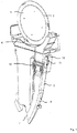
- the Fig. 1 and 2 show schematic perspective representations of an arrangement for a sowing row of a seed drill with a singling disc 1, which can be used in a singling device to isolate grains of a granular material to be spread in a field furrow, for example seeds or fertilizer grains.
- Separating devices of this type are known as such in various embodiments.
- a pneumatically operated singling process is used to hold individual grains in the area of openings 2 of singling disc 1.
- the grains are then released in a known manner from the singling disc 1 for spreading into the furrow in the field, in order to be transported through a transport pipe 3 down to the furrow.
- the separated grains pass through an inlet opening 4 of the transport tube 3.
- the separated grains are transported along a transport path 6, which in the transport tube 3 along a transport channel 5 (see also FIG Fig. 4 and 5 below), transported to an exit opening 7.
- the transport can take place solely on the basis of the gravitational force acting on the grains.
- the transport pipe 3 is also referred to as a downpipe.
- a downward air flow is generated in the transport pipe 3 in order to further accelerate the grains in the transport channel. Then there is also talk of a shot tube.
- the transport tube 3 is curved in the lower region 8.
- a holding or mounting device 10 of a measuring device 11 is arranged in the area of an outside recess 9 of the transport pipe 3. According to Fig. 3 instructs the measuring device 11 in addition to the holding or mounting device 10 on a signal transmitter 12, which is formed, for example, as an optical signal transmitter with transmitter 12a and receiver 12b.
- the signal transmitter 12 provides a detection area 13 which, in the embodiment shown, is designed as a spatial detection area, for example an optical detection area. If a separated grain arrives during its transport through the transport pipe 3 through the detection area 13, a measurement signal is provided with the aid of the measuring device 11, which indicates that the grain has passed the detection area 13, i.e. has been transported along the transport pipe 3 and has been applied. In this way it is possible, for example, to determine the grains which are spread through the transport pipe 3 in a time segment.
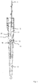
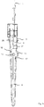
- FIGS Fig. 4 and 5 show schematic sectional views for an arrangement with a section of the transport tube 3 and the separating disk 1.
- FIGS Fig. 4 and 5 show schematic sectional views for an arrangement with a section of the transport tube 3 and the separating disk 1.
- FIGS Fig. 4 and 5 show schematic sectional views for an arrangement with a section of the transport tube 3 and the separating disk 1.
- FIGS Fig. 4 and 5 show schematic sectional views for an arrangement with a section of the transport tube 3 and the separating disk 1.
- Different flight curves 20, 21 show the course of the transport path for grains of different grain types in the transport pipe 3.
- the flight curves 20, 21 differ for different grains, for example seeds of maize and seeds of rape.
- the grains have different weights and different external shapes.
- the detection area 13 of the measuring device 11 can be in the horizontal direction, i.e. transversely to the transport path of the grains in the transport tube 3 between a first measuring position in Fig. 4 and a second measuring position in Fig. 5 are relocated in order to be optimally adjusted for one of the two flight curves 20, 21.
- Properties of the flight curves 20, 21 for the different grain types can be determined in advance experimentally and / or by means of simulation.
- the measuring device 11 can then provide prepared and user-selectable measurement positions for different grain types, which the user can select and set manually or automatically via a control connected to the measuring device 11 when the respective seed type is to be applied.
- Fig. 3 shows more details for an example of a manual adjustability or adjustability of the measuring device 11.
- Fig. 4 and 5 Alternatively, a motor-driven mechanism can be provided in order to effect the displacement of the detection area 13.
- the measuring device 11 is arranged on the transport tube 3 in an area in which the transport channel 5 has a constriction 16.
- the holding or mounting device 10 of the measuring device 11 is at least partially arranged in an outer recess 17 of the transport tube 3, which supports a space-saving design.
Landscapes
- Life Sciences & Earth Sciences (AREA)
- Soil Sciences (AREA)
- Environmental Sciences (AREA)
- Sowing (AREA)
Claims (12)
- Agencement pour une ligne de semis d'un semoir, comprenant- un tube de transfert (3) ;- un orifice d'entrée (4), qui est créé dans le tube de transfert (3) et par l'intermédiaire duquel le tube de transfert (3) est susceptible de réceptionner des graines désolidarisées à partir d'un dispositif de désolidarisation ;- un orifice de sortie, qui est créé dans le tube de transfert (3) et par l'intermédiaire duquel des graines désolidarisées peuvent quitter le tube de transfert (3), pour l'épandage des graines désolidarisées dans un sillon :- un conduit de transfert (5), qui est créé dans le tube de transfert (3) et à travers lequel les graines désolidarisées arrivent le long d'un trajet de transfert (6) de l'orifice d'entrée (4) vers l'orifice de sortie (7) ; et- un dispositif de mesure (11), qui est créé sur le conduit de transfert (5) et qui est aménagé pour détecter les graines transférées le long du conduit de transfert (5) sur le trajet de transfert (6), lorsque celles-ci sont transférées à travers une zone de détection (13) du dispositif de mesure (11), laquelle s'étend à la transversale du trajet de transfert (6) dans le conduit de transfert (5) ;la zone de détection (13) étant déplaçable entre une première position de mesure, dans laquelle la zone de détection (13) détecte un premier tronçon du conduit de transfert (5) et une deuxième position de mesure, dans laquelle la zone de détection (13) détecte un deuxième tronçon du conduit de transfert (5), qui est différent du premier tronçon, caractérisé en ce que pour déplacer la zone de détection (13), il est prévu sur le dispositif de mesure (11) un mécanisme de déplacement manuel ou actionné par moteur.
- Agencement selon la revendication 1, caractérisé en ce que la zone de détection (13) est déplaçable dans une direction transversale au trajet de transfert (6).
- Agencement selon la revendication 1 ou 2, caractérisé en ce que le premier et le deuxième tronçon du conduit de transfert (5) se chevauchent partiellement.
- Agencement selon au moins l'une quelconque des revendications précédentes, caractérisé en ce que la zone de détection (13) du dispositif de mesure (11) est conçue de sorte à détecter essentiellement complètement le conduit de transfert (5) dans une première direction transversale au trajet de transfert (6).
- Agencement selon au moins l'une quelconque des revendications précédentes, caractérisé en ce que, par le déplacement entre la première et la deuxième position de mesure, le conduit de transfert (5) est détectable essentiellement complètement par la zone de détection (13) du dispositif de mesure (11) dans une deuxième direction transversale au trajet de transfert (6) et à la première direction.
- Agencement selon au moins l'une quelconque des revendications précédentes, caractérisé en ce que la zone de détection (13) est une zone de détection (13) spatiale.
- Agencement selon au moins l'une quelconque des revendications précédentes, caractérisé en ce que le dispositif de mesure (11) est placé sur le tube de transfert (3) dans un tronçon de tube rétréci, dans lequel le conduit de transfert (5) comporte un rétrécissement conçu au moins unilatéralement.
- Agencement selon au moins l'une quelconque des revendications précédentes, caractérisé en ce que le dispositif de mesure (11) est placé au moins partiellement dans un creux externe sur le tube de transfert (3).
- Agencement selon au moins l'une quelconque des revendications précédentes, caractérisé en ce que le dispositif de mesure (11) comporte un dispositif de mesure optique.
- Ligne de semis pour un semoir, comprenant un agencement selon au moins l'une quelconque des revendications précédentes.
- Semoir, comprenant au moins une ligne de semis selon la revendication 10.
- Procédé, destiné à la détection métrologique de graines, lors de l'épandage de graines désolidarisées au moyen d'une ligne de semis d'un semoir, comprenant les étapes suivantes :- désolidariser des graines au moyen d'un dispositif de désolidarisation ;- introduire les graines désolidarisées à travers un orifice d'entrée (4) d'un tube de transfert (3) dans un conduit de transfert (5), lequel est placé dans le tube de transfert (3) ;- transférer les graines désolidarisées le long d'un trajet de transfert (6) dans le conduit de transfert (5) vers un orifice de sortie (7) du tube de transfert (3), à cet effet, les graines désolidarisées étant détectées au moyen d'un dispositif de mesure (11) lorsque les graines désolidarisées sont transférées à travers une zone de détection (13) du dispositif de mesure (11), laquelle s'étend à la transversale du trajet de transfert (6) dans le conduit de transfert (5) ;- épandre les graines désolidarisées à travers l'orifice de sortie (7) du tube de transfert (3), et- épandre les graines désolidarisées dans un sillon ;lors de la détection des graines désolidarisées, la zone de détection (13) du dispositif de mesure (11) étant déplacée entre une première position de mesure, dans laquelle la zone de détection (13) détecte un premier tronçon du conduit de transfert (5) et une deuxième position de mesure, dans laquelle la zone de détection (13) détecte un deuxième tronçon du conduit de transfert (5) qui est différent du premier tronçon, caractérisé en ce que pour déplacer la zone de détection (13), il est prévu sur le dispositif de mesure (11) un mécanisme de déplacement manuel ou actionné par moteur.
Priority Applications (2)
| Application Number | Priority Date | Filing Date | Title |
|---|---|---|---|
| ES18205469T ES2908593T3 (es) | 2018-11-09 | 2018-11-09 | Disposición para una hilera de siembra de una máquina de siembra, hilera de siembra, máquina de siembra y procedimiento para la detección metrológica de granos |
| EP18205469.2A EP3649843B1 (fr) | 2018-11-09 | 2018-11-09 | Dispositif pour une unité de rang de semis d'un semoir, unité de rang de semis, semoir et procédé de détection des grains |
Applications Claiming Priority (1)
| Application Number | Priority Date | Filing Date | Title |
|---|---|---|---|
| EP18205469.2A EP3649843B1 (fr) | 2018-11-09 | 2018-11-09 | Dispositif pour une unité de rang de semis d'un semoir, unité de rang de semis, semoir et procédé de détection des grains |
Publications (2)
| Publication Number | Publication Date |
|---|---|
| EP3649843A1 EP3649843A1 (fr) | 2020-05-13 |
| EP3649843B1 true EP3649843B1 (fr) | 2022-01-05 |
Family
ID=64270733
Family Applications (1)
| Application Number | Title | Priority Date | Filing Date |
|---|---|---|---|
| EP18205469.2A Active EP3649843B1 (fr) | 2018-11-09 | 2018-11-09 | Dispositif pour une unité de rang de semis d'un semoir, unité de rang de semis, semoir et procédé de détection des grains |
Country Status (2)
| Country | Link |
|---|---|
| EP (1) | EP3649843B1 (fr) |
| ES (1) | ES2908593T3 (fr) |
Family Cites Families (4)
| Publication number | Priority date | Publication date | Assignee | Title |
|---|---|---|---|---|
| DE102004004133A1 (de) * | 2004-01-28 | 2005-08-18 | Amazonen-Werke H. Dreyer Gmbh & Co. Kg | Verfahren und Vorrichtung zum optischen Zählen kleiner Körperchen |
| US7472660B2 (en) * | 2005-10-13 | 2009-01-06 | Deere & Company | Seed tube for an agricultural seeding machine |
| US8618465B2 (en) * | 2008-11-13 | 2013-12-31 | Deere & Company | Seed sensor system and method for improved seed count and seed spacing |
| US8869629B2 (en) * | 2012-03-08 | 2014-10-28 | Cnh Industrial Canada, Ltd. | System and method for monitoring agricultural product delivery |
-
2018
- 2018-11-09 ES ES18205469T patent/ES2908593T3/es active Active
- 2018-11-09 EP EP18205469.2A patent/EP3649843B1/fr active Active
Also Published As
| Publication number | Publication date |
|---|---|
| ES2908593T3 (es) | 2022-05-03 |
| EP3649843A1 (fr) | 2020-05-13 |
Similar Documents
| Publication | Publication Date | Title |
|---|---|---|
| DE2610223C3 (de) | Pneumatische Einzelkornsämaschine | |
| EP3409092B1 (fr) | Dispositif de singulation pour matériau granulaire comprenant un compteur de grains | |
| EP3440911A1 (fr) | Semoir à flux de grains suivi | |
| EP3335535B1 (fr) | Dispositif de transport de matériau granulaire à epandre sur une surface agricole avec une pression de singulation égale | |
| EP1415523A1 (fr) | Semoir | |
| EP4208003B1 (fr) | Procede et dispositif permettant d'adapter le fonctionnement d'un dispositif de singulation et le fonctionnement d'un dispositif de portionnement | |
| EP3241421A1 (fr) | Système de commande de machine agricole et procédé | |
| CH643982A5 (de) | Vorrichtung und verfahren zum vereinzeln und ablegen von koernigem gut, insbesondere saatgut. | |
| DE2203181B2 (de) | Verfahren und vorrichtung zum pruefen des fuellungsgrades von zigaretten | |
| EP3649843B1 (fr) | Dispositif pour une unité de rang de semis d'un semoir, unité de rang de semis, semoir et procédé de détection des grains | |
| DE102004045654A1 (de) | Elektronische Überwachungseinrichtung | |
| DE102017118594A1 (de) | Vereinzelungsvorrichtung | |
| DE10119763A1 (de) | Verfahren und Vorrichtung zur Getreideanalyse | |
| EP0805771A1 (fr) | Dispositif pour selectionner un ou plusieurs contenants a symetrie de rotation dans un flux de tels contenants transportes sous l'effet d'une pression dynamique et verin avec piston a deplacement commande | |
| EP2923545A1 (fr) | Dispositif de transport de matériau granulaire | |
| DE4345025C2 (de) | Dübelübernahmestation bei Dübeleintreibgeräten | |
| EP3108732B1 (fr) | Dispositif pour transporter granulaire sur une surface agricole avec pression de refoulement réduite | |
| EP4009762B1 (fr) | Système de dosage pour machine agricol | |
| EP4262342A1 (fr) | Procédé pour adapter l'un à l'autre le fonctionnement d'un dispositif d'individualisation et le fonctionnement d'un dispositif de portionnement | |
| EP3704923B1 (fr) | Dispositif pour un semoir agricole, procédé de séparation des semences dans un dispositif pour un semoir agricole ainsi que semoir | |
| EP3135087A1 (fr) | Dispositif de depose de materiau granulaire sur une surface agricole | |
| DE102010015913A1 (de) | Sämaschine | |
| EP3662731B1 (fr) | Machine pour l'épandage de solides granulaires avec un système de transport pneumatique | |
| EP3981239B1 (fr) | Procédé de planification et/ou de mise en oeuvre d'un processus d'apport d'engrais | |
| DE102004003702A1 (de) | Elektronische Vorrichtung zum Zählen kleiner Körperchen |
Legal Events
| Date | Code | Title | Description |
|---|---|---|---|
| PUAI | Public reference made under article 153(3) epc to a published international application that has entered the european phase |
Free format text: ORIGINAL CODE: 0009012 |
|
| STAA | Information on the status of an ep patent application or granted ep patent |
Free format text: STATUS: THE APPLICATION HAS BEEN PUBLISHED |
|
| AK | Designated contracting states |
Kind code of ref document: A1 Designated state(s): AL AT BE BG CH CY CZ DE DK EE ES FI FR GB GR HR HU IE IS IT LI LT LU LV MC MK MT NL NO PL PT RO RS SE SI SK SM TR |
|
| AX | Request for extension of the european patent |
Extension state: BA ME |
|
| STAA | Information on the status of an ep patent application or granted ep patent |
Free format text: STATUS: REQUEST FOR EXAMINATION WAS MADE |
|
| 17P | Request for examination filed |
Effective date: 20201111 |
|
| RBV | Designated contracting states (corrected) |
Designated state(s): AL AT BE BG CH CY CZ DE DK EE ES FI FR GB GR HR HU IE IS IT LI LT LU LV MC MK MT NL NO PL PT RO RS SE SI SK SM TR |
|
| GRAP | Despatch of communication of intention to grant a patent |
Free format text: ORIGINAL CODE: EPIDOSNIGR1 |
|
| STAA | Information on the status of an ep patent application or granted ep patent |
Free format text: STATUS: GRANT OF PATENT IS INTENDED |
|
| INTG | Intention to grant announced |
Effective date: 20210701 |
|
| GRAS | Grant fee paid |
Free format text: ORIGINAL CODE: EPIDOSNIGR3 |
|
| GRAA | (expected) grant |
Free format text: ORIGINAL CODE: 0009210 |
|
| STAA | Information on the status of an ep patent application or granted ep patent |
Free format text: STATUS: THE PATENT HAS BEEN GRANTED |
|
| AK | Designated contracting states |
Kind code of ref document: B1 Designated state(s): AL AT BE BG CH CY CZ DE DK EE ES FI FR GB GR HR HU IE IS IT LI LT LU LV MC MK MT NL NO PL PT RO RS SE SI SK SM TR |
|
| REG | Reference to a national code |
Ref country code: GB Ref legal event code: FG4D Free format text: NOT ENGLISH |
|
| REG | Reference to a national code |
Ref country code: CH Ref legal event code: EP |
|
| REG | Reference to a national code |
Ref country code: AT Ref legal event code: REF Ref document number: 1459694 Country of ref document: AT Kind code of ref document: T Effective date: 20220115 |
|
| REG | Reference to a national code |
Ref country code: DE Ref legal event code: R096 Ref document number: 502018008394 Country of ref document: DE |
|
| REG | Reference to a national code |
Ref country code: IE Ref legal event code: FG4D Free format text: LANGUAGE OF EP DOCUMENT: GERMAN |
|
| REG | Reference to a national code |
Ref country code: DE Ref legal event code: R081 Ref document number: 502018008394 Country of ref document: DE Owner name: KVERNELAND GROUP SOEST GMBH, DE Free format text: FORMER OWNER: KVERNELAND A/S, KLEPP ST., NO |
|
| RAP2 | Party data changed (patent owner data changed or rights of a patent transferred) |
Owner name: KVERNELAND GROUP SOEST GMBH |
|
| REG | Reference to a national code |
Ref country code: LT Ref legal event code: MG9D |
|
| REG | Reference to a national code |
Ref country code: ES Ref legal event code: FG2A Ref document number: 2908593 Country of ref document: ES Kind code of ref document: T3 Effective date: 20220503 |
|
| REG | Reference to a national code |
Ref country code: NL Ref legal event code: MP Effective date: 20220105 |
|
| PG25 | Lapsed in a contracting state [announced via postgrant information from national office to epo] |
Ref country code: NL Free format text: LAPSE BECAUSE OF FAILURE TO SUBMIT A TRANSLATION OF THE DESCRIPTION OR TO PAY THE FEE WITHIN THE PRESCRIBED TIME-LIMIT Effective date: 20220105 |
|
| REG | Reference to a national code |
Ref country code: AT Ref legal event code: PC Ref document number: 1459694 Country of ref document: AT Kind code of ref document: T Owner name: KVERNELAND GROUP SOEST GMBH, DE Effective date: 20220523 |
|
| PG25 | Lapsed in a contracting state [announced via postgrant information from national office to epo] |
Ref country code: SE Free format text: LAPSE BECAUSE OF FAILURE TO SUBMIT A TRANSLATION OF THE DESCRIPTION OR TO PAY THE FEE WITHIN THE PRESCRIBED TIME-LIMIT Effective date: 20220105 Ref country code: RS Free format text: LAPSE BECAUSE OF FAILURE TO SUBMIT A TRANSLATION OF THE DESCRIPTION OR TO PAY THE FEE WITHIN THE PRESCRIBED TIME-LIMIT Effective date: 20220105 Ref country code: PT Free format text: LAPSE BECAUSE OF FAILURE TO SUBMIT A TRANSLATION OF THE DESCRIPTION OR TO PAY THE FEE WITHIN THE PRESCRIBED TIME-LIMIT Effective date: 20220505 Ref country code: NO Free format text: LAPSE BECAUSE OF FAILURE TO SUBMIT A TRANSLATION OF THE DESCRIPTION OR TO PAY THE FEE WITHIN THE PRESCRIBED TIME-LIMIT Effective date: 20220405 Ref country code: LT Free format text: LAPSE BECAUSE OF FAILURE TO SUBMIT A TRANSLATION OF THE DESCRIPTION OR TO PAY THE FEE WITHIN THE PRESCRIBED TIME-LIMIT Effective date: 20220105 Ref country code: HR Free format text: LAPSE BECAUSE OF FAILURE TO SUBMIT A TRANSLATION OF THE DESCRIPTION OR TO PAY THE FEE WITHIN THE PRESCRIBED TIME-LIMIT Effective date: 20220105 Ref country code: BG Free format text: LAPSE BECAUSE OF FAILURE TO SUBMIT A TRANSLATION OF THE DESCRIPTION OR TO PAY THE FEE WITHIN THE PRESCRIBED TIME-LIMIT Effective date: 20220405 |
|
| PG25 | Lapsed in a contracting state [announced via postgrant information from national office to epo] |
Ref country code: PL Free format text: LAPSE BECAUSE OF FAILURE TO SUBMIT A TRANSLATION OF THE DESCRIPTION OR TO PAY THE FEE WITHIN THE PRESCRIBED TIME-LIMIT Effective date: 20220105 Ref country code: LV Free format text: LAPSE BECAUSE OF FAILURE TO SUBMIT A TRANSLATION OF THE DESCRIPTION OR TO PAY THE FEE WITHIN THE PRESCRIBED TIME-LIMIT Effective date: 20220105 Ref country code: GR Free format text: LAPSE BECAUSE OF FAILURE TO SUBMIT A TRANSLATION OF THE DESCRIPTION OR TO PAY THE FEE WITHIN THE PRESCRIBED TIME-LIMIT Effective date: 20220406 Ref country code: FI Free format text: LAPSE BECAUSE OF FAILURE TO SUBMIT A TRANSLATION OF THE DESCRIPTION OR TO PAY THE FEE WITHIN THE PRESCRIBED TIME-LIMIT Effective date: 20220105 |
|
| PG25 | Lapsed in a contracting state [announced via postgrant information from national office to epo] |
Ref country code: IS Free format text: LAPSE BECAUSE OF FAILURE TO SUBMIT A TRANSLATION OF THE DESCRIPTION OR TO PAY THE FEE WITHIN THE PRESCRIBED TIME-LIMIT Effective date: 20220505 |
|
| REG | Reference to a national code |
Ref country code: DE Ref legal event code: R097 Ref document number: 502018008394 Country of ref document: DE |
|
| PG25 | Lapsed in a contracting state [announced via postgrant information from national office to epo] |
Ref country code: SM Free format text: LAPSE BECAUSE OF FAILURE TO SUBMIT A TRANSLATION OF THE DESCRIPTION OR TO PAY THE FEE WITHIN THE PRESCRIBED TIME-LIMIT Effective date: 20220105 Ref country code: SK Free format text: LAPSE BECAUSE OF FAILURE TO SUBMIT A TRANSLATION OF THE DESCRIPTION OR TO PAY THE FEE WITHIN THE PRESCRIBED TIME-LIMIT Effective date: 20220105 Ref country code: RO Free format text: LAPSE BECAUSE OF FAILURE TO SUBMIT A TRANSLATION OF THE DESCRIPTION OR TO PAY THE FEE WITHIN THE PRESCRIBED TIME-LIMIT Effective date: 20220105 Ref country code: EE Free format text: LAPSE BECAUSE OF FAILURE TO SUBMIT A TRANSLATION OF THE DESCRIPTION OR TO PAY THE FEE WITHIN THE PRESCRIBED TIME-LIMIT Effective date: 20220105 Ref country code: DK Free format text: LAPSE BECAUSE OF FAILURE TO SUBMIT A TRANSLATION OF THE DESCRIPTION OR TO PAY THE FEE WITHIN THE PRESCRIBED TIME-LIMIT Effective date: 20220105 Ref country code: CZ Free format text: LAPSE BECAUSE OF FAILURE TO SUBMIT A TRANSLATION OF THE DESCRIPTION OR TO PAY THE FEE WITHIN THE PRESCRIBED TIME-LIMIT Effective date: 20220105 |
|
| PLBE | No opposition filed within time limit |
Free format text: ORIGINAL CODE: 0009261 |
|
| STAA | Information on the status of an ep patent application or granted ep patent |
Free format text: STATUS: NO OPPOSITION FILED WITHIN TIME LIMIT |
|
| PG25 | Lapsed in a contracting state [announced via postgrant information from national office to epo] |
Ref country code: AL Free format text: LAPSE BECAUSE OF FAILURE TO SUBMIT A TRANSLATION OF THE DESCRIPTION OR TO PAY THE FEE WITHIN THE PRESCRIBED TIME-LIMIT Effective date: 20220105 |
|
| 26N | No opposition filed |
Effective date: 20221006 |
|
| PG25 | Lapsed in a contracting state [announced via postgrant information from national office to epo] |
Ref country code: SI Free format text: LAPSE BECAUSE OF FAILURE TO SUBMIT A TRANSLATION OF THE DESCRIPTION OR TO PAY THE FEE WITHIN THE PRESCRIBED TIME-LIMIT Effective date: 20220105 |
|
| PG25 | Lapsed in a contracting state [announced via postgrant information from national office to epo] |
Ref country code: MC Free format text: LAPSE BECAUSE OF FAILURE TO SUBMIT A TRANSLATION OF THE DESCRIPTION OR TO PAY THE FEE WITHIN THE PRESCRIBED TIME-LIMIT Effective date: 20220105 |
|
| REG | Reference to a national code |
Ref country code: CH Ref legal event code: PL |
|
| P01 | Opt-out of the competence of the unified patent court (upc) registered |
Effective date: 20230525 |
|
| GBPC | Gb: european patent ceased through non-payment of renewal fee |
Effective date: 20221109 |
|
| REG | Reference to a national code |
Ref country code: BE Ref legal event code: MM Effective date: 20221130 |
|
| PG25 | Lapsed in a contracting state [announced via postgrant information from national office to epo] |
Ref country code: LI Free format text: LAPSE BECAUSE OF NON-PAYMENT OF DUE FEES Effective date: 20221130 Ref country code: CH Free format text: LAPSE BECAUSE OF NON-PAYMENT OF DUE FEES Effective date: 20221130 |
|
| PG25 | Lapsed in a contracting state [announced via postgrant information from national office to epo] |
Ref country code: LU Free format text: LAPSE BECAUSE OF NON-PAYMENT OF DUE FEES Effective date: 20221109 |
|
| PG25 | Lapsed in a contracting state [announced via postgrant information from national office to epo] |
Ref country code: IE Free format text: LAPSE BECAUSE OF NON-PAYMENT OF DUE FEES Effective date: 20221109 Ref country code: GB Free format text: LAPSE BECAUSE OF NON-PAYMENT OF DUE FEES Effective date: 20221109 |
|
| PG25 | Lapsed in a contracting state [announced via postgrant information from national office to epo] |
Ref country code: BE Free format text: LAPSE BECAUSE OF NON-PAYMENT OF DUE FEES Effective date: 20221130 |
|
| PG25 | Lapsed in a contracting state [announced via postgrant information from national office to epo] |
Ref country code: HU Free format text: LAPSE BECAUSE OF FAILURE TO SUBMIT A TRANSLATION OF THE DESCRIPTION OR TO PAY THE FEE WITHIN THE PRESCRIBED TIME-LIMIT; INVALID AB INITIO Effective date: 20181109 |
|
| PG25 | Lapsed in a contracting state [announced via postgrant information from national office to epo] |
Ref country code: CY Free format text: LAPSE BECAUSE OF FAILURE TO SUBMIT A TRANSLATION OF THE DESCRIPTION OR TO PAY THE FEE WITHIN THE PRESCRIBED TIME-LIMIT Effective date: 20220105 |
|
| PG25 | Lapsed in a contracting state [announced via postgrant information from national office to epo] |
Ref country code: MK Free format text: LAPSE BECAUSE OF FAILURE TO SUBMIT A TRANSLATION OF THE DESCRIPTION OR TO PAY THE FEE WITHIN THE PRESCRIBED TIME-LIMIT Effective date: 20220105 |
|
| PG25 | Lapsed in a contracting state [announced via postgrant information from national office to epo] |
Ref country code: TR Free format text: LAPSE BECAUSE OF FAILURE TO SUBMIT A TRANSLATION OF THE DESCRIPTION OR TO PAY THE FEE WITHIN THE PRESCRIBED TIME-LIMIT Effective date: 20220105 |
|
| PG25 | Lapsed in a contracting state [announced via postgrant information from national office to epo] |
Ref country code: MT Free format text: LAPSE BECAUSE OF FAILURE TO SUBMIT A TRANSLATION OF THE DESCRIPTION OR TO PAY THE FEE WITHIN THE PRESCRIBED TIME-LIMIT Effective date: 20220105 |
|
| PGFP | Annual fee paid to national office [announced via postgrant information from national office to epo] |
Ref country code: DE Payment date: 20251119 Year of fee payment: 8 |
|
| PGFP | Annual fee paid to national office [announced via postgrant information from national office to epo] |
Ref country code: AT Payment date: 20251120 Year of fee payment: 8 |
|
| PGFP | Annual fee paid to national office [announced via postgrant information from national office to epo] |
Ref country code: IT Payment date: 20251125 Year of fee payment: 8 |
|
| PGFP | Annual fee paid to national office [announced via postgrant information from national office to epo] |
Ref country code: FR Payment date: 20251126 Year of fee payment: 8 |
|
| PGFP | Annual fee paid to national office [announced via postgrant information from national office to epo] |
Ref country code: ES Payment date: 20251229 Year of fee payment: 8 |