EP3649843A1 - Dispositif pour un rang de semis d'un semoir, rang de semis, semoir et procédé de détection des grains - Google Patents
Dispositif pour un rang de semis d'un semoir, rang de semis, semoir et procédé de détection des grains Download PDFInfo
- Publication number
- EP3649843A1 EP3649843A1 EP18205469.2A EP18205469A EP3649843A1 EP 3649843 A1 EP3649843 A1 EP 3649843A1 EP 18205469 A EP18205469 A EP 18205469A EP 3649843 A1 EP3649843 A1 EP 3649843A1
- Authority
- EP
- European Patent Office
- Prior art keywords
- transport
- grains
- detection area
- measuring device
- transport channel
- Prior art date
- Legal status (The legal status is an assumption and is not a legal conclusion. Google has not performed a legal analysis and makes no representation as to the accuracy of the status listed.)
- Granted
Links
Images


Classifications
-
- A—HUMAN NECESSITIES
- A01—AGRICULTURE; FORESTRY; ANIMAL HUSBANDRY; HUNTING; TRAPPING; FISHING
- A01C—PLANTING; SOWING; FERTILISING
- A01C7/00—Sowing
- A01C7/08—Broadcast seeders; Seeders depositing seeds in rows
- A01C7/10—Devices for adjusting the seed-box ; Regulation of machines for depositing quantities at intervals
- A01C7/102—Regulating or controlling the seed rate
- A01C7/105—Seed sensors
-
- A—HUMAN NECESSITIES
- A01—AGRICULTURE; FORESTRY; ANIMAL HUSBANDRY; HUNTING; TRAPPING; FISHING
- A01C—PLANTING; SOWING; FERTILISING
- A01C7/00—Sowing
- A01C7/20—Parts of seeders for conducting and depositing seed
- A01C7/206—Seed pipes
Definitions
- the invention relates to an arrangement for a seed row of a seeder, a seed row and a seeder. Furthermore, the invention relates to a method for the metrological detection of grains of a granular material when spreading individual grains by means of a seed row of a seeder.
- a granular material for example seed material or additive such as pesticide or fertilizer
- a storage container for example a storage container
- the separated grains are then brought to a field furrow through a transport pipe, which is also referred to as a downpipe or shot pipe.
- a transport pipe which is also referred to as a downpipe or shot pipe.
- the separated grains are transported along a transport path, which the grains pass through in a transport channel formed in the transport tube, solely due to the gravitational force. It can be provided to use an air flow to accelerate the grains along the transport path in the transport pipe to the field furrow.
- the object of the invention is to provide an improved technology for an arrangement for a seed row of a seed drill, a seed row and a seed drill, with which the process of spreading individual grains can be optimized.
- an arrangement for a seed row of a seeder comprises: a transport pipe; an entrance opening on the Transport tube is formed and through which the transport tube can receive individual grains of granular material from a separating device; an exit opening which is formed on the transport pipe and through which the separated grains can leave the transport pipe for discharging the separated grains into a field furrow; a transport channel which is formed in the transport pipe and through which the separated grains pass along a transport path from the entrance opening to the exit opening; and a measuring device which is formed on the transport channel and is set up to detect the individual grains transported along the transport channel on the transport path when they are transported through a detection region of the measuring device which extends transversely to the transport path in the transport channel.
- the detection area can be shifted between a first measurement position, in which the detection area detects a first section of the transport channel, and a second measurement position, in which the detection area detects a second section of the transport channel, which is different from the first section.
- a method for the metrological detection of grains of a granular material when spreading individual grains, for example seed grains, by means of a seed row of a seeder.
- the method has the following: separating grains of a granular material by means of a separating device, introducing the separated grains through an inlet opening of a transport tube in a transport duct which is arranged in the transport duct, transporting the separated grains along a transport path in the transport duct to an outlet opening of the Transport tube, whereby the separated grains are detected by means of a measuring device if the separated grains are transported through a detection area of the measuring device which extends transversely to the transport path in the transport channel, discharging the separated grains through the outlet opening of the transport pipe and discharging the separated grains in a field furrow, the detection area of the measuring device during the detection of the individual grains between a first measurement position, in which the detection area a first section t of the transport channel is detected, and a second measuring position is shifted, in which the detection
- the detection area of the measuring device during the detection of the separated grains is shifted between a first measurement position, in which the detection area detects a first section of the transport channel, and a second measurement position, in which the detection area detects a second section of the transport channel, which is different from the first section .
- the shift between the different measuring positions makes it possible for the measuring device to adjust or adapt to different courses of the transport route for the grains of the granular material in the transport channel. More than two measurement positions can be provided.
- the shift between the measurement positions can take place depending on the grain type, for example seed grain type or fertilizer type, which is to be applied in the respective application situation using the seed row.
- Properties of the flight or transport route for the grains of the different grain types can be determined beforehand experimentally and / or by means of simulation. In this way, depending on the type or type of grain, it can be determined in which area of the transport channel the grains of the respective grain type pass the area in which the measuring device is arranged. By shifting the detection area, it can then be ensured that the grains of the respective grain type pass the detection area with an optimized probability, for example approximately in the middle.
- the user can be provided with several preset shifting or measuring positions, which can be selected and set depending on the grain type. Continuous adjustability along the displacement path between different measurement positions can be provided.
- a transmitter and a receiver can be arranged opposite one another on the transport tube.
- a transceiver can be used, wherein measurement signals emitted by the transmitter of the transceiver can be reflected on a reflecting element on the opposite side of the transport channel, in order then to be received by the receiver of the transceiver.
- the transport pipe can be a downpipe, which means that in this embodiment the individual grains are transported in the transport channel solely on the basis of the gravitational force along the transport path.
- the transport tube can be a shot tube, in which the individual grains are accelerated in the transport tube in addition to the gravitational force, in particular by means of an air flow which extends from the direction of the inlet opening of the transport tube towards the outlet opening of the transport tube moves.
- a manual or a motor-driven displacement mechanism can be provided on the measuring device for moving the detection area.
- the measuring device for forming the detection area in the different measurement positions can have a sensor line along which different sensors are activated and deactivated in order to form the detection areas in the different measurement positions. By activating and deactivating different sensors along the sensor line, the detection area is shifted between the first and the second and optionally further measurement positions.
- the measuring device can be displaceable in a direction transverse to the transport route.
- the detection area can be displaced in the longitudinal direction of the transport path and / or obliquely thereto.
- the first and the second section of the transport channel can partially overlap.
- the first and the second sections of the transport channel, which are detected by the detection area in the first and the second measurement position, can spatially overlap in the measurement positions.
- the detection area of the measuring device can be designed to be essentially completely detecting the transport channel in a first direction transverse to the transport path.
- Such an embodiment can be implemented, for example, in that a transmitter and a receiver of the measuring device are arranged on opposite sides of the transport tube, so that a detection area formed between them extends over the entire intermediate section of the transport channel.
- the transport channel itself remains free of elements of the measuring device and is thus completely available for the transport of the grains without this being hindered by the measuring device.
- the transport channel can be detected essentially completely by the detection area of the measuring device in a second direction transverse to the transport path and to the first direction.
- the detection area can be a spatial detection area.
- the detection area can be designed as a point or line in cross section, wherein a plurality of point or line-shaped detection areas can be provided, for example with the aid of measuring elements of a sensor line with point light sources.
- the measuring device can be arranged on the transport pipe in a constricted pipe section in which the transport channel has a constriction formed at least on one side.
- the measuring device can be arranged at least partially in an outside recess on the transport tube.
- the outside recess can be arranged in the region of the constriction of the transport channel.
- the at least partial reception of the measuring device in the outside recess on the transport pipe supports a space-saving installation of the transport pipe with the measuring device accommodated thereon in a seed row.
- a holder of the measuring device can for example be at least partially accommodated in the recess on the outside.
- the measuring device can be exchangeably arranged on the transport tube, so that an exchange is made possible.
- the measuring device can have an optical measuring device.
- the optical measuring device can be formed with an optical signal transmitter, for example a combination of an optical transmitter and an assigned receiver.
- the measuring device can have a capacitive and / or an inductive measuring device.
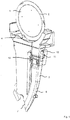
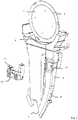
- Fig. 1 and 2nd show schematic perspective representations of an arrangement for a seed row of a seeder with a separating disc 1, which can be used in a separating device to separate grains of a granular material to be spread into a furrow, for example seed grains or fertilizer grains.
- Separation devices of this type are known as such in various embodiments.
- a pneumatically operated singling process is used to hold individual grains in the area of openings 2 of the singling disk 1.
- the grains are then released from the separating disc 1 in a known manner in order to be discharged into the field furrow, in order to be transported downward to the field furrow through a transport pipe 3.
- the separated grains pass through an inlet opening 4 of the transport pipe 3.
- the separated grains are transported along a transport path 6, which in the transport pipe 3 along a transport channel 5 (cf. also Fig. 4 and 5 below) runs, transported to an exit opening 7.
- the transport can take place solely on the basis of the gravitational force acting on the grains.
- the transport pipe 3 is also referred to as a down pipe.
- it can be provided to generate a downward air flow in the transport tube 3 in order to further accelerate the grains in the transport channel. Then we also speak of a shot tube.
- the transport tube 3 is curved in the lower region 8.
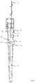
- a holding or mounting device 10 of a measuring device 11 is arranged in the area of an outside recess 9 of the transport tube 3. According to Fig. 3 points the measuring device 11 next to the holding or mounting device 10 on a signal transmitter 12, which is formed for example as an optical signal transmitter with transmitter 12a and receiver 12b.
- a detection area 13 is provided, which in the embodiment shown is designed as a spatial detection area, for example an optical detection area. If an individual grain reaches the detection area 13 when it is transported through the transport tube 3, a measuring signal is provided with the aid of the measuring device 11, which indicates that the grain has passed the detection area 13, that is to say has been transported along the transport tube 3 and has been discharged. In this way, it is possible, for example, to determine the grains which are discharged through the transport tube 3 in one time segment.
- Fig. 4 and 5 show schematic sectional views for an arrangement with a section of the transport tube 3 and the singling disc 1.
- Different flight curves 20, 21 show the course of the transport path for grains of different types of grain in the transport pipe 3.
- the flight curves 20, 21 differ for different grains, for example seeds of maize and seeds of rapeseed.
- the grains are of different weights and have different external shapes.
- the detection area 13 of the measuring device 11 in the horizontal direction, that is to say transversely to the transport path of the grains in the transport tube 3 between a first measurement position in FIG Fig. 4 and a second measurement position in Fig. 5 be shifted so as to be optimized for one of the two flight curves 20, 21.
- Properties of the flight curves 20, 21 for the different grain types can be determined beforehand experimentally and / or by means of simulation.
- the measuring device 11 can then provide measurement positions which are prepared and can be selected by the user for different types of grain and which the user can select and set automatically or manually via a controller connected to the measuring device 11 if the respective seed grain type is to be applied.
- Fig. 3 shows details of an example of a manual adjustability or adjustability of the measuring device 11.
- Rotatable adjusting elements 14, 15 can be manually adjusted by the user in order to shift the detection area 13 transversely to the transport path 6 (cf. Fig. 4 and 5 ).
- a motor-driven mechanism can be provided in order to effect the displacement of the detection area 13.
- the measuring device 11 is arranged on the transport tube 3 in an area in which the transport channel 5 has a constriction 16.
- the holding or mounting device 10 of the measuring device 11 is at least partially arranged in an outer recess 17 of the transport tube 3, which supports a space-saving design.
Landscapes
- Life Sciences & Earth Sciences (AREA)
- Soil Sciences (AREA)
- Environmental Sciences (AREA)
- Sowing (AREA)
Priority Applications (2)
| Application Number | Priority Date | Filing Date | Title |
|---|---|---|---|
| ES18205469T ES2908593T3 (es) | 2018-11-09 | 2018-11-09 | Disposición para una hilera de siembra de una máquina de siembra, hilera de siembra, máquina de siembra y procedimiento para la detección metrológica de granos |
| EP18205469.2A EP3649843B1 (fr) | 2018-11-09 | 2018-11-09 | Dispositif pour une unité de rang de semis d'un semoir, unité de rang de semis, semoir et procédé de détection des grains |
Applications Claiming Priority (1)
| Application Number | Priority Date | Filing Date | Title |
|---|---|---|---|
| EP18205469.2A EP3649843B1 (fr) | 2018-11-09 | 2018-11-09 | Dispositif pour une unité de rang de semis d'un semoir, unité de rang de semis, semoir et procédé de détection des grains |
Publications (2)
| Publication Number | Publication Date |
|---|---|
| EP3649843A1 true EP3649843A1 (fr) | 2020-05-13 |
| EP3649843B1 EP3649843B1 (fr) | 2022-01-05 |
Family
ID=64270733
Family Applications (1)
| Application Number | Title | Priority Date | Filing Date |
|---|---|---|---|
| EP18205469.2A Active EP3649843B1 (fr) | 2018-11-09 | 2018-11-09 | Dispositif pour une unité de rang de semis d'un semoir, unité de rang de semis, semoir et procédé de détection des grains |
Country Status (2)
| Country | Link |
|---|---|
| EP (1) | EP3649843B1 (fr) |
| ES (1) | ES2908593T3 (fr) |
Citations (4)
| Publication number | Priority date | Publication date | Assignee | Title |
|---|---|---|---|---|
| EP1560157A2 (fr) * | 2004-01-28 | 2005-08-03 | Amazonen-Werke H. Dreyer GmbH & Co. KG | Méthode et dispositif pour le comptage optique de petits objets |
| US20070084387A1 (en) * | 2005-10-13 | 2007-04-19 | Mariman Nathan A | Seed tube for an agricultural seeding machine |
| US20110303137A1 (en) * | 2008-11-13 | 2011-12-15 | Tevs Nikolai R | Seed sensor system and method for improved seed count and seed spacing |
| US8869629B2 (en) * | 2012-03-08 | 2014-10-28 | Cnh Industrial Canada, Ltd. | System and method for monitoring agricultural product delivery |
-
2018
- 2018-11-09 ES ES18205469T patent/ES2908593T3/es active Active
- 2018-11-09 EP EP18205469.2A patent/EP3649843B1/fr active Active
Patent Citations (4)
| Publication number | Priority date | Publication date | Assignee | Title |
|---|---|---|---|---|
| EP1560157A2 (fr) * | 2004-01-28 | 2005-08-03 | Amazonen-Werke H. Dreyer GmbH & Co. KG | Méthode et dispositif pour le comptage optique de petits objets |
| US20070084387A1 (en) * | 2005-10-13 | 2007-04-19 | Mariman Nathan A | Seed tube for an agricultural seeding machine |
| US20110303137A1 (en) * | 2008-11-13 | 2011-12-15 | Tevs Nikolai R | Seed sensor system and method for improved seed count and seed spacing |
| US8869629B2 (en) * | 2012-03-08 | 2014-10-28 | Cnh Industrial Canada, Ltd. | System and method for monitoring agricultural product delivery |
Also Published As
| Publication number | Publication date |
|---|---|
| EP3649843B1 (fr) | 2022-01-05 |
| ES2908593T3 (es) | 2022-05-03 |
Similar Documents
| Publication | Publication Date | Title |
|---|---|---|
| EP2932818B1 (fr) | Dispositif d'épandage et procédé d'épandage de produit granulaire | |
| EP3409092B1 (fr) | Dispositif de singulation pour matériau granulaire comprenant un compteur de grains | |
| DE102014110035A1 (de) | Landwirtschaftliche Sämaschine und Verfahren für eine landwirtschaftliche Sämaschine | |
| EP3335535B1 (fr) | Dispositif de transport de matériau granulaire à epandre sur une surface agricole avec une pression de singulation égale | |
| EP1415523A1 (fr) | Semoir | |
| EP4062733B1 (fr) | Procédé de détermination de l'emplacement d'un centre de gravité d'une portion des granulés | |
| DE3530514C2 (fr) | ||
| EP1882405B1 (fr) | Semoir | |
| EP4208003B1 (fr) | Procede et dispositif permettant d'adapter le fonctionnement d'un dispositif de singulation et le fonctionnement d'un dispositif de portionnement | |
| DE102013008708A1 (de) | Sämaschine | |
| DE102017118594A1 (de) | Vereinzelungsvorrichtung | |
| EP2923545B1 (fr) | Dispositif de transport de matériau granulaire | |
| EP3649843B1 (fr) | Dispositif pour une unité de rang de semis d'un semoir, unité de rang de semis, semoir et procédé de détection des grains | |
| EP3135087B1 (fr) | Dispositif de dépose de matériau granulaire sur une surface agricole | |
| EP3108732B1 (fr) | Dispositif pour transporter granulaire sur une surface agricole avec pression de refoulement réduite | |
| DE4345025C2 (de) | Dübelübernahmestation bei Dübeleintreibgeräten | |
| DE102007051702A1 (de) | Pneumatisch beaufschlagter Saatführungskanal eines Säschares | |
| WO2020178438A1 (fr) | Dispositif pour un semoir agricole, procédé de séparation de graines dans un dispositif pour un semoir agricole ainsi que semoir agricole | |
| DE102010015913A1 (de) | Sämaschine | |
| EP3662731B1 (fr) | Machine pour l'épandage de solides granulaires avec un système de transport pneumatique | |
| EP3981239B1 (fr) | Procédé de planification et/ou de mise en oeuvre d'un processus d'apport d'engrais | |
| DE202008004115U1 (de) | Pneumatische Verteileinrichtung einer landwirtschaftlichen Verteilmaschine | |
| EP1932413B1 (fr) | Dispositif destiné au comptage optique de petits corps | |
| DE102004003702A1 (de) | Elektronische Vorrichtung zum Zählen kleiner Körperchen | |
| DE102015116947A1 (de) | Vorrichtung und Verfahren zur Charakterisierung der Masseverteilung von Streugutpartikeln |
Legal Events
| Date | Code | Title | Description |
|---|---|---|---|
| PUAI | Public reference made under article 153(3) epc to a published international application that has entered the european phase |
Free format text: ORIGINAL CODE: 0009012 |
|
| STAA | Information on the status of an ep patent application or granted ep patent |
Free format text: STATUS: THE APPLICATION HAS BEEN PUBLISHED |
|
| AK | Designated contracting states |
Kind code of ref document: A1 Designated state(s): AL AT BE BG CH CY CZ DE DK EE ES FI FR GB GR HR HU IE IS IT LI LT LU LV MC MK MT NL NO PL PT RO RS SE SI SK SM TR |
|
| AX | Request for extension of the european patent |
Extension state: BA ME |
|
| STAA | Information on the status of an ep patent application or granted ep patent |
Free format text: STATUS: REQUEST FOR EXAMINATION WAS MADE |
|
| 17P | Request for examination filed |
Effective date: 20201111 |
|
| RBV | Designated contracting states (corrected) |
Designated state(s): AL AT BE BG CH CY CZ DE DK EE ES FI FR GB GR HR HU IE IS IT LI LT LU LV MC MK MT NL NO PL PT RO RS SE SI SK SM TR |
|
| GRAP | Despatch of communication of intention to grant a patent |
Free format text: ORIGINAL CODE: EPIDOSNIGR1 |
|
| STAA | Information on the status of an ep patent application or granted ep patent |
Free format text: STATUS: GRANT OF PATENT IS INTENDED |
|
| INTG | Intention to grant announced |
Effective date: 20210701 |
|
| GRAS | Grant fee paid |
Free format text: ORIGINAL CODE: EPIDOSNIGR3 |
|
| GRAA | (expected) grant |
Free format text: ORIGINAL CODE: 0009210 |
|
| STAA | Information on the status of an ep patent application or granted ep patent |
Free format text: STATUS: THE PATENT HAS BEEN GRANTED |
|
| AK | Designated contracting states |
Kind code of ref document: B1 Designated state(s): AL AT BE BG CH CY CZ DE DK EE ES FI FR GB GR HR HU IE IS IT LI LT LU LV MC MK MT NL NO PL PT RO RS SE SI SK SM TR |
|
| REG | Reference to a national code |
Ref country code: GB Ref legal event code: FG4D Free format text: NOT ENGLISH |
|
| REG | Reference to a national code |
Ref country code: CH Ref legal event code: EP |
|
| REG | Reference to a national code |
Ref country code: AT Ref legal event code: REF Ref document number: 1459694 Country of ref document: AT Kind code of ref document: T Effective date: 20220115 |
|
| REG | Reference to a national code |
Ref country code: DE Ref legal event code: R096 Ref document number: 502018008394 Country of ref document: DE |
|
| REG | Reference to a national code |
Ref country code: IE Ref legal event code: FG4D Free format text: LANGUAGE OF EP DOCUMENT: GERMAN |
|
| REG | Reference to a national code |
Ref country code: DE Ref legal event code: R081 Ref document number: 502018008394 Country of ref document: DE Owner name: KVERNELAND GROUP SOEST GMBH, DE Free format text: FORMER OWNER: KVERNELAND A/S, KLEPP ST., NO |
|
| RAP2 | Party data changed (patent owner data changed or rights of a patent transferred) |
Owner name: KVERNELAND GROUP SOEST GMBH |
|
| REG | Reference to a national code |
Ref country code: LT Ref legal event code: MG9D |
|
| REG | Reference to a national code |
Ref country code: ES Ref legal event code: FG2A Ref document number: 2908593 Country of ref document: ES Kind code of ref document: T3 Effective date: 20220503 |
|
| REG | Reference to a national code |
Ref country code: NL Ref legal event code: MP Effective date: 20220105 |
|
| PG25 | Lapsed in a contracting state [announced via postgrant information from national office to epo] |
Ref country code: NL Free format text: LAPSE BECAUSE OF FAILURE TO SUBMIT A TRANSLATION OF THE DESCRIPTION OR TO PAY THE FEE WITHIN THE PRESCRIBED TIME-LIMIT Effective date: 20220105 |
|
| REG | Reference to a national code |
Ref country code: AT Ref legal event code: PC Ref document number: 1459694 Country of ref document: AT Kind code of ref document: T Owner name: KVERNELAND GROUP SOEST GMBH, DE Effective date: 20220523 |
|
| PG25 | Lapsed in a contracting state [announced via postgrant information from national office to epo] |
Ref country code: SE Free format text: LAPSE BECAUSE OF FAILURE TO SUBMIT A TRANSLATION OF THE DESCRIPTION OR TO PAY THE FEE WITHIN THE PRESCRIBED TIME-LIMIT Effective date: 20220105 Ref country code: RS Free format text: LAPSE BECAUSE OF FAILURE TO SUBMIT A TRANSLATION OF THE DESCRIPTION OR TO PAY THE FEE WITHIN THE PRESCRIBED TIME-LIMIT Effective date: 20220105 Ref country code: PT Free format text: LAPSE BECAUSE OF FAILURE TO SUBMIT A TRANSLATION OF THE DESCRIPTION OR TO PAY THE FEE WITHIN THE PRESCRIBED TIME-LIMIT Effective date: 20220505 Ref country code: NO Free format text: LAPSE BECAUSE OF FAILURE TO SUBMIT A TRANSLATION OF THE DESCRIPTION OR TO PAY THE FEE WITHIN THE PRESCRIBED TIME-LIMIT Effective date: 20220405 Ref country code: LT Free format text: LAPSE BECAUSE OF FAILURE TO SUBMIT A TRANSLATION OF THE DESCRIPTION OR TO PAY THE FEE WITHIN THE PRESCRIBED TIME-LIMIT Effective date: 20220105 Ref country code: HR Free format text: LAPSE BECAUSE OF FAILURE TO SUBMIT A TRANSLATION OF THE DESCRIPTION OR TO PAY THE FEE WITHIN THE PRESCRIBED TIME-LIMIT Effective date: 20220105 Ref country code: BG Free format text: LAPSE BECAUSE OF FAILURE TO SUBMIT A TRANSLATION OF THE DESCRIPTION OR TO PAY THE FEE WITHIN THE PRESCRIBED TIME-LIMIT Effective date: 20220405 |
|
| PG25 | Lapsed in a contracting state [announced via postgrant information from national office to epo] |
Ref country code: PL Free format text: LAPSE BECAUSE OF FAILURE TO SUBMIT A TRANSLATION OF THE DESCRIPTION OR TO PAY THE FEE WITHIN THE PRESCRIBED TIME-LIMIT Effective date: 20220105 Ref country code: LV Free format text: LAPSE BECAUSE OF FAILURE TO SUBMIT A TRANSLATION OF THE DESCRIPTION OR TO PAY THE FEE WITHIN THE PRESCRIBED TIME-LIMIT Effective date: 20220105 Ref country code: GR Free format text: LAPSE BECAUSE OF FAILURE TO SUBMIT A TRANSLATION OF THE DESCRIPTION OR TO PAY THE FEE WITHIN THE PRESCRIBED TIME-LIMIT Effective date: 20220406 Ref country code: FI Free format text: LAPSE BECAUSE OF FAILURE TO SUBMIT A TRANSLATION OF THE DESCRIPTION OR TO PAY THE FEE WITHIN THE PRESCRIBED TIME-LIMIT Effective date: 20220105 |
|
| PG25 | Lapsed in a contracting state [announced via postgrant information from national office to epo] |
Ref country code: IS Free format text: LAPSE BECAUSE OF FAILURE TO SUBMIT A TRANSLATION OF THE DESCRIPTION OR TO PAY THE FEE WITHIN THE PRESCRIBED TIME-LIMIT Effective date: 20220505 |
|
| REG | Reference to a national code |
Ref country code: DE Ref legal event code: R097 Ref document number: 502018008394 Country of ref document: DE |
|
| PG25 | Lapsed in a contracting state [announced via postgrant information from national office to epo] |
Ref country code: SM Free format text: LAPSE BECAUSE OF FAILURE TO SUBMIT A TRANSLATION OF THE DESCRIPTION OR TO PAY THE FEE WITHIN THE PRESCRIBED TIME-LIMIT Effective date: 20220105 Ref country code: SK Free format text: LAPSE BECAUSE OF FAILURE TO SUBMIT A TRANSLATION OF THE DESCRIPTION OR TO PAY THE FEE WITHIN THE PRESCRIBED TIME-LIMIT Effective date: 20220105 Ref country code: RO Free format text: LAPSE BECAUSE OF FAILURE TO SUBMIT A TRANSLATION OF THE DESCRIPTION OR TO PAY THE FEE WITHIN THE PRESCRIBED TIME-LIMIT Effective date: 20220105 Ref country code: EE Free format text: LAPSE BECAUSE OF FAILURE TO SUBMIT A TRANSLATION OF THE DESCRIPTION OR TO PAY THE FEE WITHIN THE PRESCRIBED TIME-LIMIT Effective date: 20220105 Ref country code: DK Free format text: LAPSE BECAUSE OF FAILURE TO SUBMIT A TRANSLATION OF THE DESCRIPTION OR TO PAY THE FEE WITHIN THE PRESCRIBED TIME-LIMIT Effective date: 20220105 Ref country code: CZ Free format text: LAPSE BECAUSE OF FAILURE TO SUBMIT A TRANSLATION OF THE DESCRIPTION OR TO PAY THE FEE WITHIN THE PRESCRIBED TIME-LIMIT Effective date: 20220105 |
|
| PLBE | No opposition filed within time limit |
Free format text: ORIGINAL CODE: 0009261 |
|
| STAA | Information on the status of an ep patent application or granted ep patent |
Free format text: STATUS: NO OPPOSITION FILED WITHIN TIME LIMIT |
|
| PG25 | Lapsed in a contracting state [announced via postgrant information from national office to epo] |
Ref country code: AL Free format text: LAPSE BECAUSE OF FAILURE TO SUBMIT A TRANSLATION OF THE DESCRIPTION OR TO PAY THE FEE WITHIN THE PRESCRIBED TIME-LIMIT Effective date: 20220105 |
|
| 26N | No opposition filed |
Effective date: 20221006 |
|
| PG25 | Lapsed in a contracting state [announced via postgrant information from national office to epo] |
Ref country code: SI Free format text: LAPSE BECAUSE OF FAILURE TO SUBMIT A TRANSLATION OF THE DESCRIPTION OR TO PAY THE FEE WITHIN THE PRESCRIBED TIME-LIMIT Effective date: 20220105 |
|
| PG25 | Lapsed in a contracting state [announced via postgrant information from national office to epo] |
Ref country code: MC Free format text: LAPSE BECAUSE OF FAILURE TO SUBMIT A TRANSLATION OF THE DESCRIPTION OR TO PAY THE FEE WITHIN THE PRESCRIBED TIME-LIMIT Effective date: 20220105 |
|
| REG | Reference to a national code |
Ref country code: CH Ref legal event code: PL |
|
| P01 | Opt-out of the competence of the unified patent court (upc) registered |
Effective date: 20230525 |
|
| GBPC | Gb: european patent ceased through non-payment of renewal fee |
Effective date: 20221109 |
|
| REG | Reference to a national code |
Ref country code: BE Ref legal event code: MM Effective date: 20221130 |
|
| PG25 | Lapsed in a contracting state [announced via postgrant information from national office to epo] |
Ref country code: LI Free format text: LAPSE BECAUSE OF NON-PAYMENT OF DUE FEES Effective date: 20221130 Ref country code: CH Free format text: LAPSE BECAUSE OF NON-PAYMENT OF DUE FEES Effective date: 20221130 |
|
| PG25 | Lapsed in a contracting state [announced via postgrant information from national office to epo] |
Ref country code: LU Free format text: LAPSE BECAUSE OF NON-PAYMENT OF DUE FEES Effective date: 20221109 |
|
| PG25 | Lapsed in a contracting state [announced via postgrant information from national office to epo] |
Ref country code: IE Free format text: LAPSE BECAUSE OF NON-PAYMENT OF DUE FEES Effective date: 20221109 Ref country code: GB Free format text: LAPSE BECAUSE OF NON-PAYMENT OF DUE FEES Effective date: 20221109 |
|
| PG25 | Lapsed in a contracting state [announced via postgrant information from national office to epo] |
Ref country code: BE Free format text: LAPSE BECAUSE OF NON-PAYMENT OF DUE FEES Effective date: 20221130 |
|
| PG25 | Lapsed in a contracting state [announced via postgrant information from national office to epo] |
Ref country code: HU Free format text: LAPSE BECAUSE OF FAILURE TO SUBMIT A TRANSLATION OF THE DESCRIPTION OR TO PAY THE FEE WITHIN THE PRESCRIBED TIME-LIMIT; INVALID AB INITIO Effective date: 20181109 |
|
| PG25 | Lapsed in a contracting state [announced via postgrant information from national office to epo] |
Ref country code: CY Free format text: LAPSE BECAUSE OF FAILURE TO SUBMIT A TRANSLATION OF THE DESCRIPTION OR TO PAY THE FEE WITHIN THE PRESCRIBED TIME-LIMIT Effective date: 20220105 |
|
| PG25 | Lapsed in a contracting state [announced via postgrant information from national office to epo] |
Ref country code: MK Free format text: LAPSE BECAUSE OF FAILURE TO SUBMIT A TRANSLATION OF THE DESCRIPTION OR TO PAY THE FEE WITHIN THE PRESCRIBED TIME-LIMIT Effective date: 20220105 |
|
| PG25 | Lapsed in a contracting state [announced via postgrant information from national office to epo] |
Ref country code: TR Free format text: LAPSE BECAUSE OF FAILURE TO SUBMIT A TRANSLATION OF THE DESCRIPTION OR TO PAY THE FEE WITHIN THE PRESCRIBED TIME-LIMIT Effective date: 20220105 |
|
| PG25 | Lapsed in a contracting state [announced via postgrant information from national office to epo] |
Ref country code: MT Free format text: LAPSE BECAUSE OF FAILURE TO SUBMIT A TRANSLATION OF THE DESCRIPTION OR TO PAY THE FEE WITHIN THE PRESCRIBED TIME-LIMIT Effective date: 20220105 |
|
| PGFP | Annual fee paid to national office [announced via postgrant information from national office to epo] |
Ref country code: DE Payment date: 20251119 Year of fee payment: 8 |
|
| PGFP | Annual fee paid to national office [announced via postgrant information from national office to epo] |
Ref country code: AT Payment date: 20251120 Year of fee payment: 8 |
|
| PGFP | Annual fee paid to national office [announced via postgrant information from national office to epo] |
Ref country code: IT Payment date: 20251125 Year of fee payment: 8 |
|
| PGFP | Annual fee paid to national office [announced via postgrant information from national office to epo] |
Ref country code: FR Payment date: 20251126 Year of fee payment: 8 |
|
| PGFP | Annual fee paid to national office [announced via postgrant information from national office to epo] |
Ref country code: ES Payment date: 20251229 Year of fee payment: 8 |