EP3649839B1 - Attelage de remorque réglable en hauteur - Google Patents
Attelage de remorque réglable en hauteur Download PDFInfo
- Publication number
- EP3649839B1 EP3649839B1 EP19204596.1A EP19204596A EP3649839B1 EP 3649839 B1 EP3649839 B1 EP 3649839B1 EP 19204596 A EP19204596 A EP 19204596A EP 3649839 B1 EP3649839 B1 EP 3649839B1
- Authority
- EP
- European Patent Office
- Prior art keywords
- slide
- sensor
- guides
- pins
- along
- Prior art date
- Legal status (The legal status is an assumption and is not a legal conclusion. Google has not performed a legal analysis and makes no representation as to the accuracy of the status listed.)
- Active
Links
Images


Classifications
-
- A—HUMAN NECESSITIES
- A01—AGRICULTURE; FORESTRY; ANIMAL HUSBANDRY; HUNTING; TRAPPING; FISHING
- A01B—SOIL WORKING IN AGRICULTURE OR FORESTRY; PARTS, DETAILS, OR ACCESSORIES OF AGRICULTURAL MACHINES OR IMPLEMENTS, IN GENERAL
- A01B59/00—Devices specially adapted for connection between animals or tractors and agricultural machines or implements
- A01B59/04—Devices specially adapted for connection between animals or tractors and agricultural machines or implements for machines pulled or pushed by a tractor
- A01B59/042—Devices specially adapted for connection between animals or tractors and agricultural machines or implements for machines pulled or pushed by a tractor having pulling means arranged on the rear part of the tractor
-
- B—PERFORMING OPERATIONS; TRANSPORTING
- B60—VEHICLES IN GENERAL
- B60D—VEHICLE CONNECTIONS
- B60D1/00—Traction couplings; Hitches; Draw-gear; Towing devices
- B60D1/01—Traction couplings or hitches characterised by their type
- B60D1/02—Bolt or shackle-type couplings
-
- B—PERFORMING OPERATIONS; TRANSPORTING
- B60—VEHICLES IN GENERAL
- B60D—VEHICLE CONNECTIONS
- B60D1/00—Traction couplings; Hitches; Draw-gear; Towing devices
- B60D1/24—Traction couplings; Hitches; Draw-gear; Towing devices characterised by arrangements for particular functions
- B60D1/42—Traction couplings; Hitches; Draw-gear; Towing devices characterised by arrangements for particular functions for being adjustable
- B60D1/46—Traction couplings; Hitches; Draw-gear; Towing devices characterised by arrangements for particular functions for being adjustable vertically
-
- B—PERFORMING OPERATIONS; TRANSPORTING
- B60—VEHICLES IN GENERAL
- B60D—VEHICLE CONNECTIONS
- B60D1/00—Traction couplings; Hitches; Draw-gear; Towing devices
- B60D2001/001—Traction couplings; Hitches; Draw-gear; Towing devices specially adapted for use on vehicles other than cars
Definitions
- the present invention relates to an adjustable height towing device.
- the device in question is suitable for being conveniently installed on tractors or other vehicles for agricultural use, to allow the coupling of the drawbar of a trailer.
- towing devices comprising a pair of uprights facing each other, and connected by one or more cross-beams so as to define a rigid frame which can be fixed to the rear part of a tractor.
- a slide is placed between the uprights, and supports the towing hook operatively engageable with a drawbar of a trailer, for example a waggon or an agricultural machine of a different type.
- Vertical adjustment is normally carried out by sliding the slide along a pair of special guides formed in the aforementioned uprights.
- Locking means associated with the slide allow it to be blocked along the guides in a plurality of predetermined positions, selectable by the operator as required each time.
- Such locking means provide for the presence of two sets of engagement seats, distributed along each of the guides, respectively, and a pair of pins operatively associated with the slide, and slidably guided between a locking position and an unlocking position. In the locking position, the pins are inserted each in one of the engagement seats to lock the slide along the guides. In the unlocking position, the pins are unbound from the engagement seats to enable the sliding of the slide along the guides.
- the operator To adjust the height position of the hook, the operator first acts on the locking means by operating on a special handle, to make the pins of the sliding slide re-enter, then reposition the hook vertically and, once it has reached the desired position, he performs a new manoeuvre to make the side pins come out, positioning them in the engagement seats arranged along the sliding guides.
- the Applicant has observed that the pins sometimes may not come out properly, for example due to a wrong manoeuvre, due to the presence of dirt, mud or debris in the engagement seats, due to a deterioration of the opening-closing mechanism of the pins, or for other causes.
- the aim of the present invention is to overcome the limits of the state of the art and increase the operational safety of the current towing devices.
- the safety of use can be significantly increased by providing suitable sensors that are capable of detecting the correct insertion of the pins in the respective seats, and/or signalling a failed or incorrect insertion of the same so that the operator can promptly intervene to restore the safety conditions of the hook.
- the present invention relates to a towing device as defined in claim 1.
- the safety of use of the towing device is thus significantly increased.
- the presence of the sensor devices makes it possible to immediately signal to the operator the state of failed achievement of the correct locking position, so as to reduce the risk that the towing device may be accidentally used in precarious stability conditions.
- they can furthermore provide at least one of the characteristics expressed in one or more of the dependent claims.
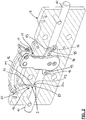
- 1 indicates an adjustable height towing device, according to the present invention.
- the device comprises a pair of uprights 2 facing each other.
- the uprights have each an inner surface 2a facing the other upright 2.
- each upright 2 has an outer surface 2b opposite to the inner surface 2a.
- These uprights 2 are connected by one or more cross-beams 3, together with which they define a frame 4.
- the frame 4 is rigidly engageable to the rear part of a tractor.
- the apparatus 1 further comprises a slide 5.
- This slide 5 is placed between the uprights 2, and can be fixed to a hook 6 which in turn can be operatively engageable with the drawbar of a trailer (not shown).
- the slide 5 has the function of supporting this hook and allowing the connection between the vehicle and the trailer.
- the slide 5 is movable along at least one substantially vertical sliding direction.
- the slide 5 is slidable along at least one guide 7 connected to the frame 4.
- a pair of guides 7 is provided, each formed on one of the uprights 2.
- each guide 7 is substantially defined by a recess or groove with a straight development, formed directly on the respective upright 2, in particular at the inner surface 2a. It should be noted that the slide 5 has two end portions 5a which slide inside the uprights 2 and, in particular, inside the respective guides 7.
- the apparatus 1 further comprises locking means 8 associated with the slide 5. These locking means 8 have the function of locking the slide 5 in a plurality of positions on the guides 7.
- each upright 2 has a plurality of engagement seats 9, for example in the form of through holes, preferably arranged along the groove which defines the guide 7.
- Each engagement seat 9 is preferably arranged at the same height as a similar engagement seat 9 made on the opposite upright 2.
- a pair of pins 10 is carried by the slide 5, and each pin 10 is configured to selectively insert into one of the engagement seats 9 made on one of the uprights 2.
- each pin 10 is slidably guided with respect to the slide 5, and is switchable between a locking position in which it is inserted in one of the engagement seats 9 to lock the slide 5, and an unlocking position in which it is unbound from the engagement seat 9 and retracted towards the slide 5, allowing it to slide along the guides 7.
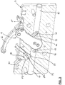
- the movement of the pins 10 between the locking position and the unlocking position can conveniently be obtained through a control mechanism 11 operable by a handle 12.
- the translation towards the unlocking position takes place in contrast with at least one return spring 13 operating between the pins 10, or other elastic members which tend to return and hold the pins themselves in the locking position.
- the control mechanism 11 provides a plate 14 constrained to the handle 12 rotatably bound to the slide 5.
- the plate 14 has a pair of arched slots 15 which operatively bind respective plungers 16 projecting radially from the pins 10.
- the manual action on the handle 12, after unbinding of a locking element 17, determines the rotation of the plate 14 and, as a result of the binding between the slots 15 and the plungers 16, the consequent displacement of the pins 10 towards the unlocking position, in contrast to the action of the return spring 13.
- the invention can also be implemented in the presence of control mechanisms of different types, depending on requirements.
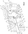
- a tubular body 18 inside which the pins 10 are partially inserted is provided associated to the slide 5.
- the tubular body can rotate around its own axis on command of the handle 12, to control the movement of the pins 10, for example by means of respective plungers 16, sliding inside helicoidal (not visible) slits formed on the pins 10.
- the control mechanism 11 provides a plate 14, integral with the handle 12, slidably bound with the slide 5.
- the plate 14 has a pair of oblique slots 15 which operatively bind respective plungers 16 projecting radially from the pins 10.
- the manual action on the handle 12 determines the translation of the plate 14 and, as a result of the binding between the slots 15 and the plungers 16, the consequent displacement of the pins 10 in the unlocking position, in contrast to the action of the return spring 13.
- the device 1 further comprises sensor devices 19 for detecting the correct insertion of the pins 10 in the respective engagement seats 9, in conjunction with the actuation of the locking position.
- At least one sensor S comprising at least a first portion P1 carried by the slide 5 and a second portion P2 carried by at least one of the pins 10 is in fact provided.
- the sensor S is switchable between a first and a second operating condition to emit a warning signal following a relative displacement between the first portion P1 and the second portion P2.
- the senor S essentially comprises an inductive detector 20 and a ferromagnetic reference 21 carried by one and the other of said first and second portions P1, P2 respectively.
- inductive detectors such as for example capacitive, magnetic, optical, ultrasonic detectors or even mechanical microswitches.
- the inductive detector 20 and the ferromagnetic reference 21 form part of the first portion P1 and of the second portion P2 respectively.
- the first portion P1 can be installed on at least one of the uprights 2 at the guide 7.
- the inductive detector 20 constituting the first portion P1 is bound along a hole 22 formed in the slide 5, radially with respect to the pin 10, and having an open end towards the pin itself.
- the ferromagnetic reference 21 constituting the second portion P2 can be obtained in turn directly on the pin 10, by means of a surface discontinuity configured to face, when the pin 10 is in the locked position, at an active end 20a of the inductive detector 20.
- this surface discontinuity can be defined by a circumferential throat or a recess or of a suitable depth, formed in the outer surface of the pin 10.
- the sensor S is suitable for detecting the correct insertion of each pin 10 in the locking condition in one of the respective engagement seats 9.
- a displacement of the ferromagnetic reference 21 is determined with respect to the inductive detector 20.
- the consequent variation of the magnetic field near the active end 20a determines the switching of the state of the inductive detector 20, from the first to the second operating condition, with simultaneous emission or interruption of the warning signal.
- the warning signal possibly after being processed through an electronic control unit neither described nor illustrated since it can be made in a known way, can determine the activation of at least one signalling device, for example of the optical and/or acoustic type.
- This signalling device installed for example in the driving position and/or in near the towing device, is operatively connected to the sensor S and configured to promptly inform the operator of the sudden displacement of the pins 10 from the correct locking position.
- connection between the sensor S and the signalling device can be obtained by cable, but in a preferred embodiment it is provided that the sensor S is equipped with a transmitter configured to send wirelessly the warning signal to the signalling device itself.
- the absence of connection cables facilitates the excursion of the slide 5 during the hook height adjustment and eliminates the risk of damage to the cables themselves.
- the signalling device can provide for the use of a pair of warning lights, respectively green and red, to indicate the correct achievement of the locking position and of the unlocking position and/or any non-compliant operating status to the lock position respectively.
- At least the red light can be combined with an acoustic indicator, to reinforce the signal of the state of danger.
- the correct insertion of the pin 10 in the locking condition determines the emission by the sensor S of a consent signal.
- the consent signal can be processed by the electronic control unit to enable the activation of the green light or other optical or acoustic consent signal, which signals the correct insertion of the pins 10 to the operator occupying the driving position of the tractor.
- the emission of the enabling signal by the respective sensor S is absent, in the absence of which the electronic control unit can command the signalling device to emit the alarm signal.
- the invention allows to achieve an effective and constant control of the correct connection of the slide to the uprights, with a consequent increase in the safety of use of the towing device.
- the invention is also suitable for being implemented also by providing changes to existing towing devices, through simple operations and/or replacement of a limited number of parts.
- the described example can be implemented by simple machining or replacement of one of the pins 10, in order to produce the ferromagnetic reference 21, and of the slide 5 for the purpose of housing the inductive detector 20.
- the housing of the inductive sensor and of the ferromagnetic reference 21 inside the slide 5 conveniently protects them from exposure to external atmospheric and environmental agents, as well as from possible collisions with foreign bodies.
Landscapes
- Engineering & Computer Science (AREA)
- Mechanical Engineering (AREA)
- Life Sciences & Earth Sciences (AREA)
- Transportation (AREA)
- Zoology (AREA)
- Soil Sciences (AREA)
- Environmental Sciences (AREA)
- Guiding Agricultural Machines (AREA)
- Train Traffic Observation, Control, And Security (AREA)
- Vehicle Body Suspensions (AREA)
Claims (10)
- Attelage de remorque réglable en hauteur, comprenant un châssis (4) comportant une paire de montants (2) ;
une paire de guides (7) chacun associé à un montant (2) respectif ;
une glissière (5) pouvant glisser le long desdits guides (7) et se déplacer au moins le long d'une direction de glissement sensiblement verticale, ladite glissière (5) pouvant être fixée à un crochet (6) pour la connexion d'une remorque ;
un moyen de verrouillage (8) associé à ladite glissière (5) pour la verrouiller en plusieurs positions le long desdits guides (7) ;
dans lequel ledit moyen de verrouillage (8) comprend une pluralité de sièges d'engagement (9), agencés chacun sur chaque montant (2) le long d'une direction de développement longitudinal des guides (7), et une paire de broches (10) portées par la glissière (5), et guidées par glissement entre une position de verrouillage, dans laquelle elles sont toutes deux insérées dans l'un des sièges d'engagement (9) pour verrouiller la glissière (5) le long des guides (7), et une position de déverrouillage, dans laquelle elles sont désengagées des sièges de couplage (9) pour permettre le glissement de la glissière (5) le long des guides (7) ;
caractérisé en ce qu'il comprend également des dispositifs de capteur (19) pour détecter l'insertion correcte des broches (10) dans les sièges d'engagement (9) respectifs en la position verrouillée. - Attelage selon la revendication 1, dans lequel lesdits dispositifs de capteur (19) comprennent au moins un capteur (S) comprenant une première partie (P1) portée par la glissière (5) et une deuxième partie (P2) portée par au moins une desdites broches (10), ledit capteur (S) pouvant commuter entre un premier et un deuxième état de fonctionnement pour émettre un signal d'avertissement suite à un déplacement relatif entre la première partie (P1) et la deuxième partie (P2).
- Attelage selon la revendication 1, dans lequel lesdits dispositifs de capteur (19) comprennent au moins un capteur (S) comprenant une première partie (P1) placée à proximité de l'un des guides (7) et une deuxième partie (P2) portée par au moins une desdites broches (10), ledit capteur (S) pouvant commuter entre un premier et un deuxième état de fonctionnement pour émettre un signal d'avertissement suite à un déplacement relatif entre la première partie (P1) et la deuxième partie (P2).
- Attelage selon la revendication 2 ou 3, comprenant en outre, un dispositif de signalement connecté de manière fonctionnelle audit capteur (S) pour émettre un signal d'alarme en réponse audit signal d'avertissement.
- Attelage selon la revendication 4, dans lequel le capteur (S) est équipé d'un transmetteur configuré pour envoyer le signal d'avertissement audit dispositif de signalement par une transmission sans fil.
- Attelage selon l'une ou plusieurs des revendications précédentes, dans lequel lesdits dispositifs de capteur (19) comprennent un détecteur inductif (20) et une référence ferromagnétique (21) constituant respectivement l'une des première et deuxième parties (P1, P2).
- Attelage selon la revendication 6, dans lequel le détecteur inductif (20) et la référence ferromagnétique (21) sont portés respectivement par la glissière (5) et par ladite broche (10).
- Attelage selon l'une ou plusieurs des revendications 2 à 7, dans lequel la première partie (P1) du capteur (S) est engagée dans un trou (22) formé dans la glissière (5) et ayant une extrémité ouverte vers la broche (10).
- Attelage selon la revendication 7 ou 8, dans lequel la référence ferromagnétique (21) du capteur (S) comprend une discontinuité de surface obtenue sur la broche (10) et orientée de manière radiale vers le détecteur inductif (20) en la position verrouillée.
- Attelage selon la revendication 9, dans lequel la discontinuité de surface est définie par un évidement formé sur une surface extérieure de la broche (10).
Applications Claiming Priority (1)
| Application Number | Priority Date | Filing Date | Title |
|---|---|---|---|
| IT102018000010086A IT201800010086A1 (it) | 2018-11-06 | 2018-11-06 | Dispositivo di traino ad altezza regolabile |
Publications (2)
| Publication Number | Publication Date |
|---|---|
| EP3649839A1 EP3649839A1 (fr) | 2020-05-13 |
| EP3649839B1 true EP3649839B1 (fr) | 2021-03-03 |
Family
ID=65409304
Family Applications (1)
| Application Number | Title | Priority Date | Filing Date |
|---|---|---|---|
| EP19204596.1A Active EP3649839B1 (fr) | 2018-11-06 | 2019-10-22 | Attelage de remorque réglable en hauteur |
Country Status (2)
| Country | Link |
|---|---|
| EP (1) | EP3649839B1 (fr) |
| IT (1) | IT201800010086A1 (fr) |
Families Citing this family (1)
| Publication number | Priority date | Publication date | Assignee | Title |
|---|---|---|---|---|
| CN114312178B (zh) * | 2021-11-24 | 2024-03-22 | 北京特种机械研究所 | 浮动装置牵引自适应连接装置及连接系统 |
Family Cites Families (4)
| Publication number | Priority date | Publication date | Assignee | Title |
|---|---|---|---|---|
| IT1286196B1 (it) * | 1996-08-08 | 1998-07-08 | C B M Spa | Sistema di controllo e sicurezza a gestione elettronica per collegamento fra una motrice ed un veicolo trainato |
| IT1287175B1 (it) * | 1996-11-15 | 1998-08-04 | Meccaniche G Grassi Di Luigi G | Dispositivo di traino per un trattore e simili |
| GB201014235D0 (en) * | 2010-08-26 | 2010-10-13 | Agco Sa | Tractor rear hitch |
| ITMI20112056A1 (it) * | 2011-11-11 | 2013-05-12 | Orlandi S P A V | Apparato di collegamento per veicoli da traino |
-
2018
- 2018-11-06 IT IT102018000010086A patent/IT201800010086A1/it unknown
-
2019
- 2019-10-22 EP EP19204596.1A patent/EP3649839B1/fr active Active
Also Published As
| Publication number | Publication date |
|---|---|
| EP3649839A1 (fr) | 2020-05-13 |
| IT201800010086A1 (it) | 2020-05-06 |
Similar Documents
| Publication | Publication Date | Title |
|---|---|---|
| US9573548B2 (en) | Operator protection apparatus with an over-center linkage | |
| EP2417007B1 (fr) | Système de coupleur pneumatique / électrique automatique pour une combinaison de véhicules tracteur - remorque | |
| EP1847448A2 (fr) | Remorque à longueur variable pour unités de tracteurs à pneus | |
| EP3649839B1 (fr) | Attelage de remorque réglable en hauteur | |
| US20170240010A1 (en) | Movable tow bar assembly | |
| EP3578500B1 (fr) | Flèche télescopique à extension rotative et système de verrouillage | |
| EP2828104B1 (fr) | Système de verrouillage automatique pour ensemble attelage de véhicule | |
| US7976052B1 (en) | Lock and positioning assembly for the tongue of a steerable trailer | |
| ITMI962386A1 (it) | Dispositivo di traino per un trattore e simili | |
| EP1974963B1 (fr) | Dispositif de dépannage pour véhicule agricole ou industriel | |
| EP2643175B1 (fr) | Dispositif de fixation d'un timon de remorque | |
| KR101498362B1 (ko) | 굴삭기의 부속기구 이탈방지 안전장치 | |
| US20140265245A1 (en) | Removable gooseneck hitch safety chain bracket | |
| US8915515B1 (en) | Gooseneck hitching system | |
| US20200198712A1 (en) | Operating mechanism of work vehicle | |
| KR101461256B1 (ko) | 반자동식 툴 체인저 | |
| GB2042316A (en) | Tractor hitches | |
| US20220048344A1 (en) | Position and draft control mechanism for an implement coupled to vehicle hitch | |
| EP1688277B1 (fr) | Coulisseau pour crochet de remorque pour véhicules | |
| CA2812503C (fr) | Dispositif d'entrainement pour train d'atterrissage | |
| CA2378750C (fr) | Ensemble anti-mouvement de cisaille pour camion gros porteur | |
| EP1044831B1 (fr) | Attelage pour véhicules, en particulier pour tracteurs agricoles, muni d'une broche de positionnement pourvu d'un verrouillage de sécurité | |
| EP3441242B1 (fr) | Ensemble de barre de remorquage mobile | |
| AU2017202996B2 (en) | Movable tow bar assembly | |
| IT201900016559A1 (it) | Sistema di traino, assieme e metodo di gestione |
Legal Events
| Date | Code | Title | Description |
|---|---|---|---|
| PUAI | Public reference made under article 153(3) epc to a published international application that has entered the european phase |
Free format text: ORIGINAL CODE: 0009012 |
|
| STAA | Information on the status of an ep patent application or granted ep patent |
Free format text: STATUS: THE APPLICATION HAS BEEN PUBLISHED |
|
| STAA | Information on the status of an ep patent application or granted ep patent |
Free format text: STATUS: REQUEST FOR EXAMINATION WAS MADE |
|
| AK | Designated contracting states |
Kind code of ref document: A1 Designated state(s): AL AT BE BG CH CY CZ DE DK EE ES FI FR GB GR HR HU IE IS IT LI LT LU LV MC MK MT NL NO PL PT RO RS SE SI SK SM TR |
|
| AX | Request for extension of the european patent |
Extension state: BA ME |
|
| 17P | Request for examination filed |
Effective date: 20200430 |
|
| RBV | Designated contracting states (corrected) |
Designated state(s): AL AT BE BG CH CY CZ DE DK EE ES FI FR GB GR HR HU IE IS IT LI LT LU LV MC MK MT NL NO PL PT RO RS SE SI SK SM TR |
|
| GRAP | Despatch of communication of intention to grant a patent |
Free format text: ORIGINAL CODE: EPIDOSNIGR1 |
|
| STAA | Information on the status of an ep patent application or granted ep patent |
Free format text: STATUS: GRANT OF PATENT IS INTENDED |
|
| RIC1 | Information provided on ipc code assigned before grant |
Ipc: B60D 1/46 20060101ALI20200923BHEP Ipc: A01B 59/042 20060101AFI20200923BHEP |
|
| INTG | Intention to grant announced |
Effective date: 20201013 |
|
| GRAS | Grant fee paid |
Free format text: ORIGINAL CODE: EPIDOSNIGR3 |
|
| GRAA | (expected) grant |
Free format text: ORIGINAL CODE: 0009210 |
|
| STAA | Information on the status of an ep patent application or granted ep patent |
Free format text: STATUS: THE PATENT HAS BEEN GRANTED |
|
| AK | Designated contracting states |
Kind code of ref document: B1 Designated state(s): AL AT BE BG CH CY CZ DE DK EE ES FI FR GB GR HR HU IE IS IT LI LT LU LV MC MK MT NL NO PL PT RO RS SE SI SK SM TR |
|
| REG | Reference to a national code |
Ref country code: GB Ref legal event code: FG4D |
|
| REG | Reference to a national code |
Ref country code: CH Ref legal event code: EP Ref country code: AT Ref legal event code: REF Ref document number: 1366151 Country of ref document: AT Kind code of ref document: T Effective date: 20210315 |
|
| REG | Reference to a national code |
Ref country code: DE Ref legal event code: R096 Ref document number: 602019002948 Country of ref document: DE |
|
| REG | Reference to a national code |
Ref country code: IE Ref legal event code: FG4D |
|
| REG | Reference to a national code |
Ref country code: LT Ref legal event code: MG9D |
|
| PG25 | Lapsed in a contracting state [announced via postgrant information from national office to epo] |
Ref country code: LT Free format text: LAPSE BECAUSE OF FAILURE TO SUBMIT A TRANSLATION OF THE DESCRIPTION OR TO PAY THE FEE WITHIN THE PRESCRIBED TIME-LIMIT Effective date: 20210303 Ref country code: NO Free format text: LAPSE BECAUSE OF FAILURE TO SUBMIT A TRANSLATION OF THE DESCRIPTION OR TO PAY THE FEE WITHIN THE PRESCRIBED TIME-LIMIT Effective date: 20210603 Ref country code: GR Free format text: LAPSE BECAUSE OF FAILURE TO SUBMIT A TRANSLATION OF THE DESCRIPTION OR TO PAY THE FEE WITHIN THE PRESCRIBED TIME-LIMIT Effective date: 20210604 Ref country code: FI Free format text: LAPSE BECAUSE OF FAILURE TO SUBMIT A TRANSLATION OF THE DESCRIPTION OR TO PAY THE FEE WITHIN THE PRESCRIBED TIME-LIMIT Effective date: 20210303 Ref country code: BG Free format text: LAPSE BECAUSE OF FAILURE TO SUBMIT A TRANSLATION OF THE DESCRIPTION OR TO PAY THE FEE WITHIN THE PRESCRIBED TIME-LIMIT Effective date: 20210603 Ref country code: HR Free format text: LAPSE BECAUSE OF FAILURE TO SUBMIT A TRANSLATION OF THE DESCRIPTION OR TO PAY THE FEE WITHIN THE PRESCRIBED TIME-LIMIT Effective date: 20210303 |
|
| REG | Reference to a national code |
Ref country code: NL Ref legal event code: MP Effective date: 20210303 |
|
| PG25 | Lapsed in a contracting state [announced via postgrant information from national office to epo] |
Ref country code: RS Free format text: LAPSE BECAUSE OF FAILURE TO SUBMIT A TRANSLATION OF THE DESCRIPTION OR TO PAY THE FEE WITHIN THE PRESCRIBED TIME-LIMIT Effective date: 20210303 Ref country code: SE Free format text: LAPSE BECAUSE OF FAILURE TO SUBMIT A TRANSLATION OF THE DESCRIPTION OR TO PAY THE FEE WITHIN THE PRESCRIBED TIME-LIMIT Effective date: 20210303 Ref country code: LV Free format text: LAPSE BECAUSE OF FAILURE TO SUBMIT A TRANSLATION OF THE DESCRIPTION OR TO PAY THE FEE WITHIN THE PRESCRIBED TIME-LIMIT Effective date: 20210303 Ref country code: PL Free format text: LAPSE BECAUSE OF FAILURE TO SUBMIT A TRANSLATION OF THE DESCRIPTION OR TO PAY THE FEE WITHIN THE PRESCRIBED TIME-LIMIT Effective date: 20210303 |
|
| PG25 | Lapsed in a contracting state [announced via postgrant information from national office to epo] |
Ref country code: NL Free format text: LAPSE BECAUSE OF FAILURE TO SUBMIT A TRANSLATION OF THE DESCRIPTION OR TO PAY THE FEE WITHIN THE PRESCRIBED TIME-LIMIT Effective date: 20210303 |
|
| PG25 | Lapsed in a contracting state [announced via postgrant information from national office to epo] |
Ref country code: CZ Free format text: LAPSE BECAUSE OF FAILURE TO SUBMIT A TRANSLATION OF THE DESCRIPTION OR TO PAY THE FEE WITHIN THE PRESCRIBED TIME-LIMIT Effective date: 20210303 Ref country code: EE Free format text: LAPSE BECAUSE OF FAILURE TO SUBMIT A TRANSLATION OF THE DESCRIPTION OR TO PAY THE FEE WITHIN THE PRESCRIBED TIME-LIMIT Effective date: 20210303 Ref country code: SM Free format text: LAPSE BECAUSE OF FAILURE TO SUBMIT A TRANSLATION OF THE DESCRIPTION OR TO PAY THE FEE WITHIN THE PRESCRIBED TIME-LIMIT Effective date: 20210303 |
|
| PG25 | Lapsed in a contracting state [announced via postgrant information from national office to epo] |
Ref country code: IS Free format text: LAPSE BECAUSE OF FAILURE TO SUBMIT A TRANSLATION OF THE DESCRIPTION OR TO PAY THE FEE WITHIN THE PRESCRIBED TIME-LIMIT Effective date: 20210703 Ref country code: SK Free format text: LAPSE BECAUSE OF FAILURE TO SUBMIT A TRANSLATION OF THE DESCRIPTION OR TO PAY THE FEE WITHIN THE PRESCRIBED TIME-LIMIT Effective date: 20210303 Ref country code: PT Free format text: LAPSE BECAUSE OF FAILURE TO SUBMIT A TRANSLATION OF THE DESCRIPTION OR TO PAY THE FEE WITHIN THE PRESCRIBED TIME-LIMIT Effective date: 20210705 Ref country code: RO Free format text: LAPSE BECAUSE OF FAILURE TO SUBMIT A TRANSLATION OF THE DESCRIPTION OR TO PAY THE FEE WITHIN THE PRESCRIBED TIME-LIMIT Effective date: 20210303 |
|
| REG | Reference to a national code |
Ref country code: DE Ref legal event code: R097 Ref document number: 602019002948 Country of ref document: DE |
|
| PLBE | No opposition filed within time limit |
Free format text: ORIGINAL CODE: 0009261 |
|
| STAA | Information on the status of an ep patent application or granted ep patent |
Free format text: STATUS: NO OPPOSITION FILED WITHIN TIME LIMIT |
|
| PG25 | Lapsed in a contracting state [announced via postgrant information from national office to epo] |
Ref country code: ES Free format text: LAPSE BECAUSE OF FAILURE TO SUBMIT A TRANSLATION OF THE DESCRIPTION OR TO PAY THE FEE WITHIN THE PRESCRIBED TIME-LIMIT Effective date: 20210303 Ref country code: DK Free format text: LAPSE BECAUSE OF FAILURE TO SUBMIT A TRANSLATION OF THE DESCRIPTION OR TO PAY THE FEE WITHIN THE PRESCRIBED TIME-LIMIT Effective date: 20210303 Ref country code: AL Free format text: LAPSE BECAUSE OF FAILURE TO SUBMIT A TRANSLATION OF THE DESCRIPTION OR TO PAY THE FEE WITHIN THE PRESCRIBED TIME-LIMIT Effective date: 20210303 |
|
| 26N | No opposition filed |
Effective date: 20211206 |
|
| PG25 | Lapsed in a contracting state [announced via postgrant information from national office to epo] |
Ref country code: IS Free format text: LAPSE BECAUSE OF FAILURE TO SUBMIT A TRANSLATION OF THE DESCRIPTION OR TO PAY THE FEE WITHIN THE PRESCRIBED TIME-LIMIT Effective date: 20210703 |
|
| REG | Reference to a national code |
Ref country code: BE Ref legal event code: MM Effective date: 20211031 |
|
| PG25 | Lapsed in a contracting state [announced via postgrant information from national office to epo] |
Ref country code: MC Free format text: LAPSE BECAUSE OF FAILURE TO SUBMIT A TRANSLATION OF THE DESCRIPTION OR TO PAY THE FEE WITHIN THE PRESCRIBED TIME-LIMIT Effective date: 20210303 |
|
| PG25 | Lapsed in a contracting state [announced via postgrant information from national office to epo] |
Ref country code: LU Free format text: LAPSE BECAUSE OF NON-PAYMENT OF DUE FEES Effective date: 20211022 Ref country code: BE Free format text: LAPSE BECAUSE OF NON-PAYMENT OF DUE FEES Effective date: 20211031 |
|
| REG | Reference to a national code |
Ref country code: DE Ref document number: 602019002948 Ref country code: DE Ref legal event code: R082 Ref document number: 602019002948 Country of ref document: DE Representative=s name: MUELLER SCHUPFNER & PARTNER PATENT- UND RECHTS, DE |
|
| REG | Reference to a national code |
Ref country code: DE Ref legal event code: R082 Ref document number: 602019002948 Country of ref document: DE Representative=s name: MUELLER SCHUPFNER & PARTNER PATENT- UND RECHTS, DE |
|
| PG25 | Lapsed in a contracting state [announced via postgrant information from national office to epo] |
Ref country code: IE Free format text: LAPSE BECAUSE OF NON-PAYMENT OF DUE FEES Effective date: 20211022 |
|
| REG | Reference to a national code |
Ref country code: CH Ref legal event code: PL |
|
| PG25 | Lapsed in a contracting state [announced via postgrant information from national office to epo] |
Ref country code: CY Free format text: LAPSE BECAUSE OF FAILURE TO SUBMIT A TRANSLATION OF THE DESCRIPTION OR TO PAY THE FEE WITHIN THE PRESCRIBED TIME-LIMIT Effective date: 20210303 |
|
| P01 | Opt-out of the competence of the unified patent court (upc) registered |
Effective date: 20230525 |
|
| PG25 | Lapsed in a contracting state [announced via postgrant information from national office to epo] |
Ref country code: LI Free format text: LAPSE BECAUSE OF NON-PAYMENT OF DUE FEES Effective date: 20221031 Ref country code: HU Free format text: LAPSE BECAUSE OF FAILURE TO SUBMIT A TRANSLATION OF THE DESCRIPTION OR TO PAY THE FEE WITHIN THE PRESCRIBED TIME-LIMIT; INVALID AB INITIO Effective date: 20191022 Ref country code: CH Free format text: LAPSE BECAUSE OF NON-PAYMENT OF DUE FEES Effective date: 20221031 |
|
| PG25 | Lapsed in a contracting state [announced via postgrant information from national office to epo] |
Ref country code: SI Free format text: LAPSE BECAUSE OF FAILURE TO SUBMIT A TRANSLATION OF THE DESCRIPTION OR TO PAY THE FEE WITHIN THE PRESCRIBED TIME-LIMIT Effective date: 20210303 |
|
| PG25 | Lapsed in a contracting state [announced via postgrant information from national office to epo] |
Ref country code: MK Free format text: LAPSE BECAUSE OF FAILURE TO SUBMIT A TRANSLATION OF THE DESCRIPTION OR TO PAY THE FEE WITHIN THE PRESCRIBED TIME-LIMIT Effective date: 20210303 |
|
| GBPC | Gb: european patent ceased through non-payment of renewal fee |
Effective date: 20231022 |
|
| PG25 | Lapsed in a contracting state [announced via postgrant information from national office to epo] |
Ref country code: TR Free format text: LAPSE BECAUSE OF FAILURE TO SUBMIT A TRANSLATION OF THE DESCRIPTION OR TO PAY THE FEE WITHIN THE PRESCRIBED TIME-LIMIT Effective date: 20210303 |
|
| PG25 | Lapsed in a contracting state [announced via postgrant information from national office to epo] |
Ref country code: GB Free format text: LAPSE BECAUSE OF NON-PAYMENT OF DUE FEES Effective date: 20231022 |
|
| PG25 | Lapsed in a contracting state [announced via postgrant information from national office to epo] |
Ref country code: GB Free format text: LAPSE BECAUSE OF NON-PAYMENT OF DUE FEES Effective date: 20231022 |
|
| PG25 | Lapsed in a contracting state [announced via postgrant information from national office to epo] |
Ref country code: MT Free format text: LAPSE BECAUSE OF FAILURE TO SUBMIT A TRANSLATION OF THE DESCRIPTION OR TO PAY THE FEE WITHIN THE PRESCRIBED TIME-LIMIT Effective date: 20210303 |
|
| PGFP | Annual fee paid to national office [announced via postgrant information from national office to epo] |
Ref country code: DE Payment date: 20250807 Year of fee payment: 7 |
|
| PGFP | Annual fee paid to national office [announced via postgrant information from national office to epo] |
Ref country code: AT Payment date: 20251021 Year of fee payment: 7 |
|
| PGFP | Annual fee paid to national office [announced via postgrant information from national office to epo] |
Ref country code: IT Payment date: 20251031 Year of fee payment: 7 |
|
| PGFP | Annual fee paid to national office [announced via postgrant information from national office to epo] |
Ref country code: FR Payment date: 20251029 Year of fee payment: 7 |