EP3649838B1 - Steuerung und modulares steuerungssystem eines industriellen automatisierungssystems - Google Patents
Steuerung und modulares steuerungssystem eines industriellen automatisierungssystems Download PDFInfo
- Publication number
- EP3649838B1 EP3649838B1 EP18737256.0A EP18737256A EP3649838B1 EP 3649838 B1 EP3649838 B1 EP 3649838B1 EP 18737256 A EP18737256 A EP 18737256A EP 3649838 B1 EP3649838 B1 EP 3649838B1
- Authority
- EP
- European Patent Office
- Prior art keywords
- circuit board
- main
- printed circuit
- heat sink
- backplane bus
- Prior art date
- Legal status (The legal status is an assumption and is not a legal conclusion. Google has not performed a legal analysis and makes no representation as to the accuracy of the status listed.)
- Active
Links
Images


Classifications
-
- H—ELECTRICITY
- H05—ELECTRIC TECHNIQUES NOT OTHERWISE PROVIDED FOR
- H05K—PRINTED CIRCUITS; CASINGS OR CONSTRUCTIONAL DETAILS OF ELECTRIC APPARATUS; MANUFACTURE OF ASSEMBLAGES OF ELECTRICAL COMPONENTS
- H05K7/00—Constructional details common to different types of electric apparatus
- H05K7/20—Modifications to facilitate cooling, ventilating, or heating
- H05K7/20009—Modifications to facilitate cooling, ventilating, or heating using a gaseous coolant in electronic enclosures
- H05K7/20136—Forced ventilation, e.g. by fans
- H05K7/20154—Heat dissipaters coupled to components
-
- H—ELECTRICITY
- H05—ELECTRIC TECHNIQUES NOT OTHERWISE PROVIDED FOR
- H05K—PRINTED CIRCUITS; CASINGS OR CONSTRUCTIONAL DETAILS OF ELECTRIC APPARATUS; MANUFACTURE OF ASSEMBLAGES OF ELECTRICAL COMPONENTS
- H05K7/00—Constructional details common to different types of electric apparatus
- H05K7/20—Modifications to facilitate cooling, ventilating, or heating
- H05K7/2039—Modifications to facilitate cooling, ventilating, or heating characterised by the heat transfer by conduction from the heat generating element to a dissipating body
- H05K7/20509—Multiple-component heat spreaders; Multi-component heat-conducting support plates; Multi-component non-closed heat-conducting structures
Definitions
- the invention relates to a control for an industrial automation system, comprising a main module with a housing that can be placed on a top-hat rail with a base, and with at least two circuit boards arranged in the housing, one of which is a backplane bus circuit board and one is a main circuit board, the Main circuit board is assigned a heat sink for cooling components and wherein the backplane bus circuit board provides a backplane bus for at least one expansion module that can be arranged on the side.
- the invention further relates to a modular control system with such a main module.
- controllers also called SPS (programmable memory controller), PLC (programmable logic controller) or PAC (programmable automation controller) are used to control actuators and read measurement data via sensors.
- the actuators are controlled or the sensors are read out via field devices that are connected to the controller via one or more fieldbuses.
- the field devices include, among other things, input and output modules, also called I/O (Input/Output) modules, which provide analog and/or digital input or output channels.
- I/O Input/Output
- Sensors and actuators can also each be provided with their own fieldbus connection for connection to the fieldbus.
- controls In a rule, it is intended to arrange controls in a control cabinet assigned to the industrial plant.
- controls have typical mounting elements such as a top-hat rail mount.
- the arrangement in a control cabinet sets boundary conditions for the geometric, mechanical, thermal and electrical design of the control.
- the for components of the control and especially for connections of the The space available to the controller is severely limited.
- the thermal load can also be high, so good cooling of the components must be possible with a compact design.
- performance requirements and/or the available interfaces of the control often change over time, so flexible expandability of the control is desirable.
- An expandable automation device which can be designed as a controller, in which a main module that provides the main functionality can be expanded by one or more connection modules in order to be able to operate the main module with different fieldbus systems.
- the disadvantage is that a combination of main module and connection module must always be used in order to create a functional control system.
- the publication DE 10 2012 103217 B3 discloses a module that can be mounted on a top-hat rail with a housing, a first circuit board, a second circuit board and a heat sink arranged on the first plate.
- each module includes a bus board for connecting to adjacent modules and a main board for controlling a valve.
- the publication DE 10 2006 046194 A1 discloses a heat sink for cooling an electrical component mounted thereon.
- a control according to the invention for an industrial automation system of the type mentioned is characterized in that the heat sink is arranged in the housing, is attached to the base and carries at least one of the circuit boards.
- the heat sink is thus used as a central element of the control, which carries at least one, preferably several, of the circuit boards of the main module, that is, these circuit boards are attached to the heat sink.
- the available space in the housing is used optimally, so that a compact main module with a high component density can be realized.
- the assembly of the main module is simplified because a central assembly can be pre-assembled with printed circuit boards attached to the heat sink, which is then inserted as a whole into the base and connected to it.
- the heat sink has an essentially cuboid outline and has two mutually perpendicular ones Outer surfaces are parallel to the main circuit board and the backplane bus circuit board.
- a backplane bus circuit board located in the base and a main circuit board perpendicular to it can be compactly connected to one another via the heat sink. Both the main circuit board and the backplane bus circuit board are preferably attached to the heat sink.
- At least one outer surface of the heat sink is designed as a cooling surface with which the components of the main circuit board are in thermal contact.
- the cooling surface can be designed to be stepped and have plateaus at different heights in order to contact components of the main circuit board of different heights equally well.
- the heat sink has at least one mounting foot which projects into the base and is fastened there. This means that the volume available in the base can be used to attach the heat sink and as much usable volume as possible remains in the area above the base for circuit boards.
- the vertical main circuit board can also be guided parallel to the cooling surface of the heat sink into the base. In this way, additional assembly space is created on the main circuit board without increasing the height of the main module, i.e. H. to increase the height above the top hat rail.
- an assembly comprising heat sinks and circuit boards is only attached to the base using at least one mounting foot.
- the heat sink has internal cooling fins through which cooling channels are formed.
- the heat sink thus has large outer surfaces that can be used as cooling surfaces and are in thermal contact with components to be cooled, and a high cooling performance of the heat sink is achieved.
- the inner cooling fins preferably run perpendicular to the main circuit board in order to best dissipate heat introduced there.
- the heat sink has external cooling fins, next to which at least one additional circuit board is arranged.
- the space between the outer cooling fins can be optimally used to create additional installation space for components.
- the outer cooling fins preferably run parallel to the main circuit board.
- at least one of the outer cooling fins is shorter in a longitudinal direction than other sections of the heat sink, thereby creating space for electrical connections between the main circuit board and the additional circuit board(s).
- a control system comprises a controller of the type described above with a main module and is expanded by at least one additional module in a row, the main module being connected to the at least one expansion module via a backplane bus circuit board.
- Fig. 1 shows a first exemplary embodiment of a control system in a schematic isometric view.
- the control system includes a main module 1 and, in this example, an expansion module 2.
- the control system of the Fig. 1 is intended for installation in a control cabinet.
- the usual assembly orientation is such that the in the Fig. 1 lower, invisible, side is fixed vertically in the control cabinet.
- This page is also referred to below as the assembly page.
- the ones in the Fig. 1 The top side is therefore aligned parallel to the “mounting side” and also runs vertically when installing a control cabinet. It refers to the operator or user and is hereinafter referred to as the "front”.
- the ones in the Fig. 1 The visible side facing the viewer is aligned horizontally in a typical control cabinet assembly and is hereinafter referred to as the “bottom side”.
- the ones in the Fig. 1 The invisible side facing away from the viewer, which is also aligned horizontally during control cabinet assembly, is referred to as the “top side”.
- the expansion module 2 On the left side of the main module 1 is the expansion module 2, which is shown in the figure for better illustration Fig. 1 is shown separately from main module 1. This left side of the main module 1 or the expansion module 2 is also the left side when installed in the control cabinet and is referred to as such below.
- the main module 1 has a base 10 on which a housing cover 60 is placed.
- the base 10 is preferably constructed from several components, in the present case from three locking supports 11 aligned parallel to one another, which are spaced apart from one another by spacer elements 16.
- the locking supports 11 are used to attach the main module 1 to a top-hat rail of the control cabinet, onto which they can be snapped.
- unlocking levers 13 are arranged on each locking support 11, which unlock the locking supports 11 when actuated, so that the main module 1 can be removed from the top-hat rail.
- the latching support 11 arranged on the right side of the main module 1 has protruding latching hooks 14 with which the input/output modules 3 mentioned can be latched to the main module 1.
- the input/output modules 3 are equipped with comparable locking supports 11 so that they can be placed on the top-hat rail and snapped onto the main module 1 by pushing them towards them.
- the right locking carrier 11 of the main module 1 also carries various bus contacts 15, via which a power supply and data can be transmitted to the attached input/output modules 3.
- the mechanical design of the right side of the main module 1 as well as the electrical and mechanical design of the bus contacts 15 corresponds to that of a fieldbus coupler with the same system, so that the input / output modules 3 designed for this fieldbus coupler with the same system can be connected directly to the main module 1 of the control system. This enables the input/output modules 3 to be used directly without an intermediate fieldbus and fieldbus coupler.
- the right side of the main module 1 is designed in the same form factor as the input/output modules 3. It has a section in which power supply connections 31 are positioned.
- the power supply connections 31 are designed as plug-in elements with a circuit board end connector, which is located on a printed circuit board underneath (see e.g Fig. 2a or 3a ) can be attached.
- the plug-in elements can provide various desired types of contact as power supply connections 31, for example push-in contacts, screw contacts or plug connectors.
- the housing cover 60 is designed in this area as a fold-up strip 62. This system and this form factor is preferably implemented in a comparable manner in the attachable input/output modules 3.
- the installation space of the main module 1 is larger and the housing cover 60 is formed by a main cover 61 which projects higher than the folding strip 62.
- Ventilation openings 63 are preferably formed on the bottom and top, through which a convection air flow passes from bottom to top through the main module 1.
- a fan can be placed on the bottom or top of the main cover 61, which causes a forced air flow through the main module 1 for better cooling.
- filter elements can also be provided which minimize the penetration of dirt through the ventilation openings 63.
- connections 30 are provided on the underside, whereas the front of the main module 1 has switching and signaling elements 40, for example status displays, switches or buttons.
- An antenna connection 33 is also arranged on the front.
- a memory card connection 34 with an insertion slot for, for example, a (micro) SD memory card is arranged on the front. Details about the internal structure of the main module 1 are explained in the following figures.
- the expansion module 2 which can be plugged into the left side of the main module 1, has a fundamentally comparable structure.
- the expansion module 2 also includes a base 10' which has locking supports 11' which are spaced apart from one another by spacer elements 16'. Latching hooks 14' serve for a latching connection to the main module 1.
- a housing cover 60' of the expansion module 2 is only indicated by dashed outlines and is otherwise shown transparently, so that an internal structure is visible.
- a circuit board 20 ' is arranged vertically, which is in the Fig. 1 top end carries connections 30'. These are accessible from the front of the expansion module 2.
- the structure of the expansion module 2 is also shown in more detail in the following figures.
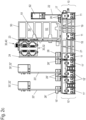
- FIG. 2a to 2c Another exemplary embodiment of a control system is shown in various views.
- the Fig. 2a and 2 B each show a schematic isometric view from two different viewing directions and the Fig. 2c shows a top view of the front of the control system.
- Housing covers 60, 60' are removed to provide insight into the internal structure of the control system.
- a main module 1 is connected to two expansion modules 2. Both expansion modules 2 are plugged in one behind the other on the left side of the main module 1, so a first expansion module 2 is directly connected to the main module 1 and a second expansion module 2 is plugged into the first expansion module 2. This is possible because the bus contacts 15 'of the expansion module 2 are looped through, so that several expansion modules 2 can be arranged in a row. For this purpose, the left side of each expansion module 2 is designed analogously to the left side of the main module 1.
- the main module 1 and the expansion modules 2 shown are constructed in a comparable manner to the first exemplary embodiment Fig. 1 .
- Small differences relate to the design of the heat sink 50, which is the case in the exemplary embodiment Fig. 2a to 2c takes up the entire height of the main module 1, whereas in the exemplary embodiment the Fig. 1 a free space remains above the heat sink 50, which can possibly be used for other purposes.
- bus contacts 15 ' which is the case in the exemplary embodiment Fig. 2a to 2c are not designed as circuit board edge connectors. Instead, plug connectors 26 and 26' are provided, which are plugged into one another and have bus contacts 15'.
- the expansion modules have the Fig. 2a to 2c also has a circuit board 20' aligned parallel to the mounting side or front side, which accommodates the plug connectors for the bus contacts 15' and which are electrically connected to another plug connector with main (circuit boards) 20' aligned perpendicular to it.
- FIG. 3a , 3b and 4a - 4c an exemplary embodiment of a main module 1 of a controller is shown in more detail.
- the Fig. 3a and 3b show the main module 1 without the housing cover 60 attached in order to gain an insight into the internal structure.
- the 4a to 4c show different views of the main module 1 with the housing cover 60 attached.
- the Fig 3a , 4b and 4a , 4b are isometric views from different viewing directions and the Fig .4c a top view of the front of the main module 1.
- the design of the base 10 of the main module 1 corresponds to that of the main modules 1 according to Fig. 1 and 2a until 2c . Reference is hereby made to the associated description.
- the present main module 1 has a plurality of circuit boards 20, the arrangement and function of which are explained in more detail below.
- a backplane bus circuit board 21 is initially arranged, which extends over the entire surface of the base frame 18. Towards the right side, the backplane bus circuit board 21 extends slightly beyond the base frame 18 to the circuit board support 17.
- the circuit board carrier 17 carries vertically a connection circuit board 22, which is inserted into the circuit board carrier 17 and extends to the bus contacts 15 on the right side of the main module 1.
- connection circuit board 22 is perpendicular to the backplane bus circuit board 21 and is connected to it via an angled plug connector 26.
- the connection circuit board 22 has at its upper end circuit board edge connectors, onto which the power supply connections 31, which are arranged in the folding strip 62 (cf. 4a to 4c ) are attached.
- the main module 1 is supplied with supply voltage, usually a direct voltage in the range of 24V, via these power supply connections 31.
- Electronic components for providing the power supply to the main module 1 and the input/output modules 3 as well as plugged-in expansion modules 2 are arranged on the connection circuit board 22.
- components arranged on circuit boards 20 are only shown as examples. It is understood that the space on all circuit boards 20 not occupied by components shown in the figures is available for electrical or electronic components. All circuit boards 20 can be populated on one or (preferably) on both sides.
- the backplane bus circuit board 21 accommodates a backplane bus for the main module 1 and any expansion modules 2.
- the backplane bus provides power supply and data lines.
- the data lines form at least one standardized and/or proprietary data bus.
- the lines of the backplane bus are passed on, for example, via the bus contacts 15 'to an inserted expansion module 2.
- main circuit board 23 vertically approximately in the middle of the main module 1, which accommodates the essential functional elements of the main module 1, in particular one or more CPU (Central Processing Unit), one or more FPGA (Field Programmable Gate Array), memory components such as RAM ( Random Access Memory), NVRAM (Non Volatile RAM), an RTC (Real Time Clock), as well as interface drivers for interface connections 32 and switching and signal elements 40.
- CPU Central Processing Unit
- FPGA Field Programmable Gate Array
- RAM Random Access Memory
- NVRAM Non Volatile RAM
- RTC Real Time Clock
- interface connections 32 and switching and signal elements 40 are arranged in the front (upper in the figures) area of the main circuit board 23.
- the switching and signal elements 40 as well as the antenna connection 33 can be arranged on the edge of the main circuit board 23, whereas the various interface connections 32 are positioned on the side of the main circuit board 23 facing away from the connection circuit board 22.
- 32 RJ-45 connections are provided as interface connections or D-SUB connections, which are also used as fieldbus connections.
- interface connections 32 can be designed as SFP (Small Formfactor Plugable) network connections, as USB connections, as display connections or even as BL/SL connections.
- the antenna connection 33 can be designed, for example, as an SMA high-frequency connection.
- a heat sink 50 is positioned between the connection circuit board 22 and the main circuit board 23.
- a cooling surface 51 facing the main circuit board 23 is in thermal contact with heat-generating components of the main circuit board 23, which are preferably arranged on the side of the circuit board facing the heat sink 50. All heat-generating components such as the CPU, the FPGAs, etc. can be cooled via the heat sink 50.
- the heat sink 50 is attached to mounting domes 19, which are formed in the base 10.
- the mounting domes 19 can be guided through an opening in the backplane bus circuit board 21, so that the heat sink is connected directly to the base 10.
- the mounting domes 19 can end below the backplane bus circuit board 21 and a screw can be inserted through the backplane bus circuit board 21 and a spacer into the Heat sink 50 guide so that the heat sink 50 is attached to the base 10 together with the backplane bus circuit board 21.
- the upper cooling channel 52 in the figures which faces the front side, is not formed over the entire width of the heat sink 50, so that a free space is created on the back of the main circuit board 23 in which a small additional circuit board 25 aligned parallel to the main circuit board 23 is positioned.
- This can be connected to the main circuit board 23 via soldering pins and/or plug connectors and can accommodate additional switching and signaling elements 40 or connections 30.
- the additional circuit board 25 provides a memory card connection 34 for accommodating a micro SD memory card and a battery connection 3 for accommodating and contacting a buffer battery to supply z.
- RTC real time clock
- the area in which the memory card connection 34 and also the battery is arranged can be covered by an access flap 64 in order to protect an inserted memory card or battery from being accidentally removed.
- a display can also be arranged in the main cover 61, or an opening through which a display is accessible. The display can be equipped with a touch function and form a switching and signaling element 40.
- the interface connections 32 positioned in the front in this exemplary embodiment can also be accessible from the underside of the main module 1 in alternative configurations, as is the case in the exemplary embodiment Fig. 1 and 2a until 2c is implemented.
- an optional additional circuit board 24 is arranged parallel to the main circuit board 23.
- This additional circuit board 24 can, for example, also have interface drivers and further interface connections 32, which are then accessible on the front or bottom of the main module 1. In this way, a larger variety of interfaces can be provided.
- the individual interface connections 32 are positioned on the main circuit board 23 and the additional circuit board 24 in such a way that they utilize the installation space between these circuit boards without interfering with each other.
- the supplementary circuit board 24 can also be used to provide particularly fast input/output channels via FPGA or GPIO (General Purpose Input Output) modules with, if necessary, direct access to the backplane bus. In this way, special input/output channels with switching times in the nanosecond range can be implemented.
- FPGA Field Programmable Gate array
- GPIO General Purpose Input Output
- the plug contact is mounted in a recess in the expansion circuit board 25 on the backplane bus circuit board 21 in order to connect expansion modules 2 to the main module 1 via its bus contacts 15 '.
- the backplane bus circuit board 21 can alternatively also be used to accommodate backup capacitors for smoothing and supporting the power supply line of the backplane bus. It is also conceivable to arrange the buffer battery of the real-time clock (RTC), which is located on the additional circuit board 25 in the exemplary embodiment shown, on the backplane bus circuit board 21. A flap or cover is then provided at the appropriate location in the housing cover 60 through which the backup battery is accessible and can be replaced.
- RTC real-time clock
- FIG. 5a to 5d and 6a to 6c A further exemplary embodiment of a main module 1 of a control system is shown.
- the Fig. 5a to 5d show the main module 1 without the housing cover 60 attached, whereas the Fig. 6a to 6c the main module 1 with the housing cover 60 attached.
- the base 10 of the main module 1 is designed as in the previous exemplary embodiments, to which reference is hereby made. The differences from the previously described exemplary embodiments are essentially discussed below.
- connection circuit board 22 and the backplane bus circuit board 21 and any additional circuit boards 25 used only a main circuit board 23 and no additional circuit board 24 are provided.
- the main circuit board 23 is arranged in the area of the left side of the main module 1.
- the switching and signaling elements 40 are in turn positioned along a portion of the upper (as shown in the figures) edge of the main circuit board 23. Due to the arrangement of the main circuit board 23 on the side in the main module 1, the interface connections 32 (again in particular RJ-45 and USB ports) which clearly protrude from the main circuit board 23 are arranged to the right in the main module 1 on the main circuit board 23.
- the heat sink 50 is brought close to the main circuit board 23 in order to be able to thermally connect heat-emitting components of the main circuit board to the heat sink 50 and to be able to cool them via the heat sink 50.
- the heat sink 50 In the upper area of the heat sink 50 it is notched out in order to be able to provide space for the interface connections 32 and the additional circuit board 25. If the cooling requirement is lower, you may be able to use the one next to the interface connections 32 located section of the heat sink 50 can be omitted, so that in turn more space for the additional circuit board 25 or space for an additional circuit board 25 aligned parallel to the front side is provided.
- Another difference from the previous exemplary embodiments relates to the design of the circuit boards 20 in the area of the connection between the backplane bus circuit board 21 and the main circuit board 23.
- the backplane bus circuit board 21 in turn opens into a plug-in contact, via which the backplane bus can be transferred to plug-in expansion modules 2.
- the backplane bus circuit board 21 is only guided in the area of this plug contact up to the edge of the base frame 18 of the main module 1.
- the backplane bus circuit board 21 ends in front of the main circuit board 23. This allows the main circuit board 23 to be extended downwards into the base 10, which means more assembly space is available. The area of the connector to the expansion modules 2 is left out.
- FIG. 5c is the main module 1 from the same viewing direction as at Fig. 5b reproduced, but the base 10 is removed in order to be able to display the main circuit board 23 in its entire size.
- This figure also shows that the heat sink 50 with a section that forms a mounting foot 57 also protrudes into the base 10, which serves to fasten it.
- an angle connector (not shown here) is arranged, which transfers the backplane bus from the main circuit board 23 to the backplane bus circuit board 21.
- both connectors can be combined in such a way that the main circuit board 23 has a connector on the front and back, which on the one hand interacts with a corresponding mating connector on the backplane bus circuit board 21 and forwards the backplane bus to the expansion module 2.
- Such an arrangement of connectors is also referred to as a 180° connector.
- the larger area of the main circuit board 23 that can be achieved in this way makes it possible to accommodate the essential functions on one circuit board, whereby the additional circuit board 24 can be omitted. For most required applications, sufficient circuit board area is provided with compact housing dimensions.
- the variant shown in these figures therefore represents a cost-effective version of the control system.
- the formation of all essential components on the main circuit board 23 also offers the advantage that that high-frequency clocked signals are routed via a few connectors, which results in good signal flow and thus the use of high clock frequencies. Saving the additional circuit board 24 also has a cost-reducing effect on the system.
- the antenna connection 33 is arranged on the additional circuit board 25. This is advantageous if the antenna connection 33 is not part of the basic equipment of the main module 1, but can be added later by retrofitting the additional circuit board 25.
- the memory card connection 34 is also formed on the main circuit board 23. All connections and function blocks necessary to operate the main module can be implemented on the main circuit board 23 or the backplane bus circuit board 21 and the connection circuit board 22. Optional features such as the antenna connection 33 can then be retrofitted via the additional circuit board. As already mentioned in connection with the previous exemplary embodiment, a backup battery for a real-time clock of the system can be located, for example, on the backplane bus circuit board 21.
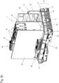
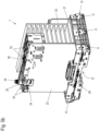
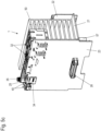
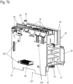
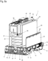
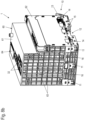
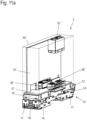
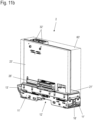
- FIG. 7a to e and 8a and 8b a further exemplary embodiment of a main module 1 of a controller is shown in different views.
- the Fig. 7a to e show the main module 1 without the housing.
- Fig. 8a is the one in the Fig. 7a
- the arrangement shown to e is inserted into a base 10.
- Fig. 8b Finally, the complete main module 1 with base 10 and attached upper housing part 60 is shown.
- the Fig. 7a and 7b are isometric oblique views of main module 1, which is shown here without base 10 and without attached housing cover 60
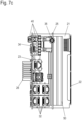
- Fig. 7c shows a top view of the main module 1, which Fig. 7d a side view and the Fig. 7e a top view of the underside of the main module 1, i.e. a view from the direction of the base 10, not shown here.
- Fig. 7a to e and 8a, b are constructed in the same way as the main modules 1 described in connection with the previous figures.
- a plurality of circuit boards 20 are present, specifically a backplane bus circuit board 21, a connection circuit board 22, a main circuit board 23 and an additional circuit board 25.
- the backplane bus circuit board 21 lies parallel to a top-hat rail onto which the main module 1 can be snapped.
- the backplane bus circuit board 21 is also located like this Fig. 8a shows, on base 10 on, which in turn has 3 locking supports 11, which are spaced apart from one another by spacer elements 16.
- the main circuit board 23, the connection circuit board 22 and the additional circuit board 25 are arranged vertically.
- the heat sink 50 is arranged centrally in the main module 1 and, in addition to its function for cooling components of the main module 1, also serves to hold several of the circuit boards 20.
- the heat sink 50 thus represents the central and supporting element of the main module 1 .It extends over the entire extent of the main module 1 in a direction perpendicular to the top-hat rail, i.e. H. in the direction in which the locking supports 11 also run.
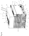
- the cooling channels 52 are also formed by inner fins 53.
- the cooling channels 52 run vertically, so that a draft of cooling air begins through the cooling channels 52 due to convection.
- a fan can be placed on the outside of the housing 60, which increases a draft through the ventilation openings 63 and the cooling channels 52.
- the inner cooling fins 53 are formed parallel to the rear wall of the circuit board 21. They thus dissipate heat from the cooling surface 51, which runs parallel to the main circuit board 23.
- the inner fins 53 do not extend to the opposite wall of the heat sink 50 in order to simplify its production in a continuous die-casting process.
- the cooling surface 51 can be designed to be stepped and have plateaus at different heights in order to contact components of the main circuit board of different heights equally well.
- the otherwise cuboid outline of the heat sink 50 is recessed in order to provide space for the interface connections 32 and / or switching and signaling elements 40, which are arranged on the main circuit board 23.
- outer cooling fins 54 are aligned parallel to the main circuit board 23. They are therefore also parallel to the additional circuit board 25, which, for example, accommodates modules for wireless communication and carries an antenna connection 33. Elements to be cooled on the additional circuit board 25 can be connected to the neighboring one Cooling fin 54 may be coupled.
- a fastening groove 55 is provided in the heat sink 50, which serves to fasten the circuit board 25.
- the main circuit board 23 is mounted on the heat sink 50.
- Fastening screws 232 can be seen, which lead through the main circuit board 23 and are screwed into corresponding threaded holes in the heat sink 50.
- the backplane bus circuit board 21 is also screwed to the heat sink 50, which has fastening holes 56 for this purpose, for example in Fig. 7a can be recognized.
- the backplane bus circuit board 21 and the main circuit board 23, as well as the additional circuit board 25, together with the heat sink 50 form a pre-assembled assembly which is electrically functional in itself and which is inserted as a whole into the base 10 for assembly.
- the heat sink 50 is comparable to the exemplary embodiment Fig. 5a-d or 6a-c mounting feet 57, with which it protrudes through a recess on the edge of the backplane bus circuit board 21 into the area of the base 10.
- Guides for the mounting feet 57 are preferably formed in the base 10, which accommodate an inserted heat sink 50 in a form-fitting manner on the side.
- the main circuit board 23 is also continued downwards beyond the level of the backplane bus circuit board 21 in the direction of the base 10 and, like the mounting feet 57, protrudes into the base 10. In this way, additional assembly space is created on the main circuit board 23 without increasing the overall height of the main module 1, ie the height above the top-hat rail.
- FIG. 7e shows the downward mounting feet 57, each with a mounting hole 58, by means of which the inserted heat sink 50 can be screwed to the base from below.
- components 211 of the backplane bus circuit board 21 can also be seen, which also protrude downwards into the base 10 and thus use its volume.
- the illustration also shows fastening screws 212 with which the backplane bus circuit board 21 is screwed to the heat sink 50.
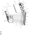
- FIG. 9 A further exemplary embodiment of a main module 1 of a controller is shown. Comparable to Fig. 8a is an isometric oblique view of the Main module 1 is shown, with a base 10 and an attached housing cover 60 not being shown in this figure.
- the basic structure corresponds to: Fig. 9 illustrated embodiment of the Figs. 7a-7e and 8a, b, particularly when it comes to assembling the heat sink 50.
- Fig. 9 illustrated embodiment of the Figs. 7a-7e and 8a, b, particularly when it comes to assembling the heat sink 50.
- it has mounting feet 57 which project downward into the base 10.
- the main board 23 and also the backplane bus board 21 are connected to the heat sink 50, for example via the ones in the Fig. 9 visible fastening screws 212.
- inner cooling fins 53 are formed parallel to the backplane bus circuit board 21 and in the upper part of the heat sink 50, which is remote from the backplane bus circuit board 21, outer cooling fins 54 are aligned perpendicular to the backplane bus circuit board 21 .
- the heat sink 50 is wider in the direction of the top-hat rail.
- a total of four outer cooling fins 54 are present parallel to the main circuit board 23 and are distributed over the entire width of the heat sink 50.
- connection made between the main circuit board 23 and the additional circuit boards 25 or between various of the additional circuit boards 25 can be connectors of various types.
- cable connectors can also be provided, particularly for transmitting high-frequency signals.
- the one in the Fig. 9 right additional board 25 a number of antenna connections 33, which are designed according to the SMA (Sub-Miniature-A) standard.
- Electronic components serving these antenna connections 33 can also be installed, for example, on the adjacent additional board also carries antenna connections 33, with high-frequency signals being exchanged between the two additional boards via miniature high-frequency plugs.
- Suitable miniature high-frequency connectors are, for example, UMTC (Ultra Miniature Telecommunications Connector) connectors.
- FIG. 9 Another difference between the exemplary embodiment Fig. 9 compared to what was previously described lies in the presence of an additional circuit board 24, which supplements the functionality of the main circuit board 23.
- This is arranged parallel to the main circuit board 23 and is connected to it via a circuit board connector which is formed in the plane of the backplane bus circuit board 21.
- memory modules 241 are arranged on the sides of the supplementary circuit board 24 opposite the main circuit board 23. The memory modules 241 are therefore accessible after removing the housing cover 60, not shown here, in order to be able to be supplemented or replaced.
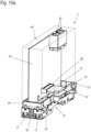
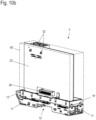
- FIG. 10a and 10b and 11a and 11b each show isometric views from different directions of two examples of an expansion module 2 for a control system.
- the first, in the Fig. 10a and 10b The example shown is also in the control system Fig. 1 shown.
- the second, in the Fig. 11a and 11b The example of the expansion module 2 shown is shown in the example Fig. 2a to 2c used.
- FIG. 10a and 10b A vertically arranged main circuit board 23' is provided, which has connections 30', specifically interface connections 32', on its upper edge (in the figures), i.e. facing the front.
- a so-called 180° plug connector is arranged, which provides plug contacts on both sides of the main circuit board 23'.
- a backplane bus circuit board 21' is inserted on the right side, which extends to a cutout in the housing cover 60', which is shown as translucent in the figure.
- this backplane bus circuit board 21' contacts a corresponding connector in the main module 1.
- a similar connector is provided on the left side of the expansion module 2 for contacting further expansion modules 2.
- a backplane bus circuit board 21 ' is provided, which is aligned parallel to the mounting side or front side and which has a connector on each of the sides of the expansion module 2.
- the main circuit board 23' is placed vertically on the backplane bus circuit board 21' and is electrically connected to it via another plug connector.
- a section of the main circuit board 23 ' protrudes into the base 10, whereby, for example, ground contact can be made via a contact spring arranged in the base 10 to the top-hat rail.
- the expansion modules 2 expand the control system with additional interfaces or application modules.
- Application modules can contain functions or combinations of interfaces. Application modules combine functions for specific application areas.
- the direct connection of the expansion modules 2 to the backplane bus of the main module 1 makes it possible to exchange a high data rate via the expansion modules 2.
- the expansion modules 2 can also be viewed as “high-speed modules” or can form an output module for particularly short switching times.
- the expansion modules 2 can also be used as memory modules, as repeaters, as camera modules, as gateways, as multiplayer or as switches, as media converters, as routers for data analysis (e.g. predictive analytics) or for providing security functions ( Safety).
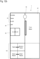
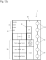
- the Fig. 12a to 12c each show a schematic top view of the front (only in the area of the main cover 61) of the main module 1.
- FIG. 12a to 12c Various possible constellations of the front with connections 30 and switching and signaling elements 40 are shown schematically and not in the exact geometric position.
- the different designs of the Fig. 12a to 12c differ in the type of connections 30 or switching and signaling elements 40 and in particular the density with which these connections 30 and switching and signaling elements 40 are arranged on the front.
- the ones in the 12a and 12b can be achieved, for example, with the basic structure of all previously shown exemplary embodiments of a main module 1.
- Fig. 12c The configuration shown with a very high density of connections 30 and switching and signaling elements 40 is preferred with the exemplary embodiments Fig. 3a and 3b and 4a to 4c and 9 can be implemented, since in these exemplary embodiments, in addition to the main circuit board 23, the additional circuit board 24 is available, in particular to accommodate additional interface connections 32.
Landscapes
- Engineering & Computer Science (AREA)
- Microelectronics & Electronic Packaging (AREA)
- Physics & Mathematics (AREA)
- Thermal Sciences (AREA)
- Cooling Or The Like Of Electrical Apparatus (AREA)
Description
- Die Erfindung betrifft eine Steuerung für ein industrielles Automatisierungssystems, aufweisend ein Hauptmodul mit einem Gehäuse, das mit einem Sockel auf eine Hutschiene aufsetzbar ist, und mit mindestens zwei in dem Gehäuse angeordneten Leiterplatten, von denen eine eine Rückwandbusleiterplatte und eine eine Hauptleiterplatte ist, wobei der Hauptleiterplatte ein Kühlkörper zur Kühlung von Komponenten zugeordnet ist und wobei die Rückwandbusleiterplatte einen Rückwandbus für mindestens ein seitlich anreihbares Erweiterungsmodul bereitstellt. Die Erfindung betrifft weiterhin ein modulares Steuerungssystem mit einem derartigen Hauptmodul.
- In industriellen Automatisierungssystemen werden Steuerungen, auch SPS (Speicher Programmierbare Steuerung), PLC (Programmable Logic Controller) oder PAC (Programmable Automation Controller) genannt, eingesetzt, um Aktoren anzusteuern und Messdaten über Sensoren einzulesen. In der Regel erfolgt die Ansteuerung der Aktoren bzw. das Auslesen der Sensoren über Feldgeräte, die über ein oder mehreren Feldbussen mit der Steuerung verbunden sind. Zu den Feldgeräten gehören u.a. Ein- und Ausgangsmodule, auch I/O (Input/Output) - Module genannt, die analoge und/oder digitale Ein- oder Ausgangskanäle bereitstellen. Häufig wird dabei nicht jedes einzelne Feldgerät unmittelbar an den Feldbus angeschlossen, sondern über einen sogenannten Feldbuskoppler, der eine Schnittstelle zwischen dem Feldbus einerseits und einem Subbus, über den eine Mehrzahl von Feldgeräten anschließbar ist, dargestellt. Sensoren und Aktoren können auch jeweils mit einem eigenen Feldbusanschluss zur Verbindung mit dem Feldbus versehen sein.
- Alternativ oder zusätzlich zur Übertragung über dem Feldbus kann vorgesehen sein, Feldgeräte auch unmittelbar in vergleichbarer Weise wie bei einem Feldbuskoppler an die Steuerung anzuschließen, indem diese einen Subbus, der mit dem eines Feldbuskopplers vergleichbar ist, bereitstellt.
- In der Regel ist vorgesehen, Steuerungen in einem der Industrieanlage zugeordneten Schaltschrank anzuordnen. Zu diesem Zweck weisen Steuerungen typische Montagelemente wie beispielsweise eine Hutschienenaufnahme auf. Die Anordnung in einem Schaltschrank setzt Randbedingungen für die geometrische, mechanische, thermische und elektrische Auslegung der Steuerung. Der für Komponenten der Steuerung und insbesondere für Anschlüsse der Steuerung verfügbare Platz ist stark eingeschränkt. Die thermische Belastung kann zudem hoch sein, sodass bei kompakter Bauweise eine gute Kühlung der Komponenten erzielbar sein muss. Zudem ändern sich Anforderungen an Leistungsfähigkeit und/oder die verfügbaren Schnittstellen der Steuerung häufig im Laufe der Zeit, sodass eine flexible Erweiterbarkeit der Steuerung wünschenswert ist.
- Aus der Druckschrift
DE 10 2014 118 389 A1 ist ein erweiterbares Automatisierungsgerät, das als Steuerung ausgebildet sein kann, bekannt, bei dem ein Hauptmodul, das die Hauptfunktionalität bereitstellt, um ein oder mehrere Anschlussmodule erweiterbar ist, um das Hauptmodul mit verschiedenen Feldbussystem betreiben zu können. Nachteilig dabei ist, dass in jedem Fall eine Kombination aus Hauptmodul und Anschlussmodul eingesetzt werden muss, um eine funktionsfähige Steuerung aufzubauen. - Die Druckschrift
DE 10 2012 103217 B3 offenbart ein an einer Hutschiene montierbares Modul mit einem Gehäuse, einer ersten Leiterplatte, einer zweiten Leiterplatte und einem auf der ersten Platte angeordneten Kühlkörper. - Die Druckschrift
WO 2009/120942 A2 offenbart ein modulares Bussystem, wobei jedes Modul eine Busplatine zur Verbindung mit benachbarten Modulen und eine Hauptplatine zur Steuerung eines Ventils umfasst. - Die Druckschrift
DE 10 2006 046194 A1 offenbart einen Kühlkörper zur Kühlung eines darauf befestigten elektrischen Bauelements. - Es ist eine Aufgabe der vorliegenden Erfindung, eine Steuerung und ein modulares Steuerungssystem bereitzustellen, die bei kompaktem Aufbau eine gute Kühlung elektronischer Komponenten ermöglicht, die flexibel in Hinblick auf zur Verfügung stehende Leiterplattenfläche und Anschlussmöglichkeiten sind und einen kompakten Aufbau aufweisen.
- Diese Aufgabe wird durch eine Steuerung und ein Steuerungssystem mit den Merkmalen des jeweiligen unabhängigen Anspruchs gelöst.
- Eine erfindungsgemäße Steuerung für ein industrielles Automatisierungssystem der eingangs genannten Art zeichnet sich dadurch aus, dass der Kühlkörper in dem Gehäuse angeordnet ist, an dem Sockel befestigt ist und mindestens eine der Leiterplatten trägt. Der Kühlkörper wird so als ein zentrales Element der Steuerung eingesetzt, das zumindest eine, bevorzugt auch mehrere der Leiterplatten des Hauptmoduls trägt, d.h. das diese Leiterplatten an dem Kühlkörper befestigt sind. Auf diese Weise wird der zur Verfügung stehende Platz im Gehäuse optimal genutzt, so dass ein kompaktes Hauptmodul mit einer hohen Bauteiledichte realisiert werden kann. Zudem wird der Zusammenbau des Hauptmoduls vereinfacht, da eine zentrale Baugruppe mit Leiterplatten, die an dem Kühlkörper befestigt sind, vormontiert werden kann, die dann als Ganzes in den Sockel eingesetzt und mit diesem verbunden wird.
- In einer vorteilhaften Ausgestaltung der Steuerung weist der Kühlkörper einen im wesentlich quaderförmigen Umriss auf und steht mit zwei zueinander senkrechten Außenflächen parallel zu der Hauptleiterplatte und der Rückwandbusleiterplatte steht. Auf diese Weise können eine im Sockel liegende Rückwandbusleiterplatte und eine dazu senkrecht stehende Hauptleiterplatte kompakt über den Kühlkörper miteinander verbunden werden. Bevorzugt sind sowohl die Hauptleiterplatte als auch die Rückwandbusleiterplatte an dem Kühlkörper befestigt.
- Weiter bevorzugt ist zumindest eine Außenfläche des Kühlkörpers als Kühlfläche ausgebildet, mit der die Komponenten der Hauptleiterplatte in thermischem Kontakt stehen. Die Kühlfläche kann dabei gestuft ausgebildet sein und Plateaus in verschiedenen Höhen aufweisen, um unterschiedlich hohe Bauelemente der Hauptleiterplatte gleichermaßen gut zu kontaktieren.
- In einer weiteren vorteilhaften Ausgestaltung der Steuerung weist der Kühlkörper mindestens einen Montagefuß auf, der bis in den Sockel hineinragt und dort befestigt ist. So kann das im Sockel zur Verfügung stehende Volumen zur Befestigung des Kühlkörpers genutzt werden und es verbleibt möglichst viel nutzbares Volumen in dem oberhalb des Sockels liegend Bereich für Leiterplatten. Zudem kann auch die senkrecht stehende Hauptleiterplatte parallel zur Kühlfläche des Kühlkörpers bis in den Sockel hineingeführt sein. Auf diese Weise wird zusätzlicher Bestückungsraum auf der Hauptleiterplatte geschaffen, ohne die Bauhöhe des Hauptmoduls, d. h. die Höhe über der Hutschiene, zu vergrößern.
- Um eine schnelle und unkomplizierte Montage des Hauptmoduls zu ermöglichen, wird eine Kühlkörper und Leiterplatten umfassende Baugruppe nur mit dem mindestens einen Montagefuß an dem Sockel befestigt.
- In einer weiteren vorteilhaften Ausgestaltung der Steuerung weist der Kühlkörper innere Kühlfinnen auf, durch die Kühlkanäle ausgebildet sind. So weist der Kühlkörper große Außenflächen auf, die als Kühlflächen eingesetzt werden können und in thermischen Kontakt mit zu kühlenden Komponenten stehen, und es wird eine hohe Kühlleistung des Kühlkörpers erzielt. Bevorzugt verlaufen die inneren Kühlfinnen senkrecht zu der Hauptleiterplatte, um von dort eingetragene Wärme bestmöglich abzuleiten.
- In einer weiteren vorteilhaften Ausgestaltung der Steuerung weist der Kühlkörper äußere Kühlfinnen auf, neben denen mindestens eine Zusatzleiterplatte angeordnet ist. Mit den Zusatzleiterplatten kann der Zwischenraum zwischen den äußeren Kühlfinnen optimal genutzt werden, um weiteren Bauraum für Komponenten zu schaffen. Die äußeren Kühlfinnen verlaufen bevorzugt parallel zu der Hauptleiterplatte. Bevorzugt ist zumindest eine der äußeren Kühlfinnen in einer Längsrichtung kürzer als andere Abschnitte des Kühlkörpers, wodurch Platz für elektrische Verbindungen zwischen der Hauptleiterplatte und der oder den Zusatzleiterplatte(n) zu schaffen.
- Ein erfindungsgemäßes Steuerungssystem umfasst eine Steuerung der zuvor beschriebenen Art mit einem Hauptmodul und ist um mindestens ein angereihtes Ergänzungsmodul erweitert, wobei das Hauptmodul über eine Rückwandbusleiterplatte mit dem mindestens einem Erweiterungsmodul verbunden ist. Es ergeben sich die im Zusammenhang mit der Steuerung beschriebenen Vorteile in einem zudem flexibel erweiterbaren System.
- Die erfindungsgemäße Steuerung und das erfindungsgemäße Steuerungssystem werden nachfolgend anhand von Ausführungsbeispielen mit Hilfe von Figu-ren näher erläutert. Die Figuren zeigen:
- Fig.1
- eine schematische isometrische Ansicht eines Steuerungssystems;
- Fig. 2 - 2c
- verschiedene Ansichten eines weiteren Ausführungsbeispiels eines Steuerungssystems;
- Fig. 3a, 3b
- zwei verschieden isometrische Ansichten eines Ausführungsbeispiels eines Hauptmoduls einer Steuerung;
- Fig. 4a - 4c
- verschiedene Ansichten des Hauptmoduls gemäß
Fig. 3a , b mit aufgesetztem Gehäusedeckel; - Fig. 5a - 5d
- verschiedene Ansichten eines weiteren Ausführungsbeispiels eines Hauptmoduls einer Steuerung, dargestellt ohne Gehäusedeckel und teilweise ohne Sockel;
- Fig. 6a - 6c
- das Hauptmodul der
Fig. 5a bis 5d mit aufgesetztem Gehäusedeckel; - Fig. 7a - 7e
- verschiedene Ansichten eines weiteren Ausführungsbeispiels eines Hauptmoduls einer Steuerung, dargestellt ohne Gehäusedeckel und ohne Sockel;
- Fig. 8a, 8b
- das Hauptmodul der
Fig. 7a bis 7e mit Sockel bzw. Sockel und aufgesetztem Gehäusedeckel; - Fig. 9
- eine isometrische Ansicht eines weiteren Ausführungsbeispiels eines Hauptmoduls einer Steuerung, dargestellt ohne Gehäusedeckel und ohne Sockel;
- Fig. 10a, 10b
- zwei verschiedene isometrische Ansichten eines ersten Ausführungsbeispiels eines Erweiterungsmoduls für ein Steuerungssystem;
- Fig. 11a, 11b
- zwei verschiedene isometrische Ansichten eines zweiten Ausführungsbeispiels eines Erweiterungsmoduls für ein Steuerungssystem; und
- Fig. 12a - 12c
- schematische Draufsichten auf ein Hauptmodul einer Steuerung in verschiedenen Anschlusskonfigurationen.
-
Fig. 1 zeigt in einer schematischen isometrischen Ansicht ein erstes Ausführungsbeispiel eines Steuerungssystems. Das Steuerungssystem umfasst ein Hauptmodul 1 sowie in diesem Beispiel ein Erweiterungsmodul 2. - Im Rahmen dieser Anmeldung kennzeichnen gleiche Bezugszeichen in allen Figuren gleiche oder gleichwirkende Elemente. Bei dem Erweiterungsmodul 2 sind zur besseren Unterscheidbarkeit Bezugszeichen der Komponenten mit einem Apostroph versehen.
- Das Steuerungssystem der
Fig. 1 ist zur Montage in einem Schaltschrank vorgesehen. Die übliche Montageorientierung ist derart, dass die in derFig. 1 untere, nicht sichtbare, Seite vertikal im Schaltschrank festgelegt ist. Diese Seite wird nachfolgend auch als Montageseite bezeichnet. Die in derFig. 1 oben liegende Seite ist somit parallel zur "Montageseite" ausgerichtet und verläuft ebenfalls bei einer Schaltschrankmontage senkrecht. Sie weist auf den Bediener oder Benutzer zu und wird nachfolgend als "Frontseite" bezeichnet. Die in derFig. 1 sichtbare, dem Betrachter zugewandte Seite ist bei einer typischen Schaltschrankmontage horizontal ausgerichtet und wird nachfolgend als "Unterseite" bezeichnet. Die in derFig. 1 nicht sichtbare, dem Betrachter abgewandte Seite, die bei der Schaltschrankmontage ebenfalls horizontal ausgerichtet wird als "Oberseite" bezeichnet. - An die in der
Fig. 1 linke Seite des Hauptmoduls 1 schließt sich das Erweiterungsmodul 2 an, das der besseren Darstellung halber in derFig. 1 getrennt vom Hauptmodul 1 wiedergegeben ist. Diese linke Seite des Hauptmoduls 1 bzw. des Erweitungsmoduls 2 ist auch bei einer Montage im Schaltschrank die linke Seite und wird nachfolgend als solche bezeichnet. An die rechte Seite des Hauptmoduls 1, die auch bei Schaltschrankmontage die rechte Seite des Hauptmoduls 1 ist und als solche nachfolgend bezeichnet wird, können sich hier nicht dargestellte Ein- / Ausgabemodule 3 anschließen. - Das Hauptmodul 1 weist einen Sockel 10 auf, auf den ein Gehäusedeckel 60 aufgesetzt ist. Der Sockel 10 ist wie in diesem Ausführungsbeispiel dargestellt bevorzugt aus mehreren Komponenten aufgebaut, vorliegend aus drei parallel zueinander ausgerichteten Rastträgern 11, die durch Abstandselemente 16 voneinander beabstandet sind. Die Rastträger 11 dienen der Befestigung des Hauptmoduls 1 an einer Hutschiene des Schaltschranks, auf die sie aufgerastet werden können.
- An der Oberseite des Hauptmoduls 1 sind an jedem Rastträger 11 Entriegelungshebel 13 angeordnet, die bei Betätigung die Rastträger 11 entriegeln, so dass das Hauptmodul 1 von der Hutschiene abgenommen werden kann. Der auf der rechten Seite des Hauptmoduls 1 angeordnete Rastträger 11 weist abstehende Rasthaken 14 auf, mit denen die genannten Ein- / Ausgabemodule 3 an das Hauptmodul 1 angerastet werden können. Die Ein- / Ausgabemodule 3 sind Ihrerseits mit vergleichbaren Rastträgern 11 ausgestattet, so dass sie auf die Hutschiene aufgesetzt und durch Heranschieben an das Hauptmodul 1 angerastet werden können.
- Der rechte Rastträger 11 des Hauptmoduls 1 trägt zudem verschiedene Buskontakte 15, über die eine Stromversorgung und auch Daten an die angesetzten Ein-/ Ausgabemodule 3 übertragen werden können. Die mechanische Ausgestaltung der rechten Seite des Hauptmoduls 1 sowie die elektrische und mechanische Ausgestaltung der Buskontakte 15 entspricht der eines systemgleichen Feldbuskopplers, so dass die für diesen systemgleichen Feldbuskoppler konstruierten Ein- / Ausgabemodule 3 sich hier unmittelbar an das Hauptmodul 1 des Steuerungssystems anschließen können. Diese ermöglicht eine direkte Verwendung der Ein- / Ausgabemodule 3 ohne einen zwischengeschalteten Feldbus und Feldbuskoppler.
- Im gleichen Formfaktor, den auch die Ein- / Ausgabemodule 3 haben, ist die rechte Seite des Hauptmoduls 1 ausgestaltet. Sie weist einen Abschnitt auf, in dem Stromversorgunganschlüsse 31 positioniert sind. Die Stromversorgungsanschlüsse 31 sind dabei als Einsteckelemente mit einem Leiterplattenendverbinder ausgebildet, die auf eine unterhalb angeordnete Leiterplatte (vgl. z.B.
Fig. 2a oder3a ) aufgesteckt werden. Die Einsteckelemente können als Stromversorgunganschlüsse 31 verschiedene gewünschte Kontaktarten bereitstellen, beispielsweise Push-In-Kontakte, Schraubkontakte oder Steckverbinder. Um die Einsteckelemente der Stromversorgungsanschlüsse 31 austauschen zu können, ist der Gehäusedeckel 60 in diesem Bereich als eine hochklappbare Klappleiste 62 ausgebildet. Dieses System und dieser Formfaktor ist bevorzugt in vergleichbarer Art und Weise bei den ansetzbaren Ein- / Ausgabemodulen 3 umgesetzt. - In seinem breiteren linken Teil ist der Bauraum des Hauptmoduls 1 größer und entsprechend der Gehäusedeckel 60 durch einen die Klappleiste 62 in der Höhe ragenden Hauptdeckel 61 gebildet. An Unter- und Oberseite sind bevorzugt Lüftungsdurchbrüche 63 ausgebildet, durch die ein Konvektionsluftstrom von unten nach oben durch das Hauptmodul 1 führt. Bei extremeren thermischen Umgebungsbedingungen kann an der Unterseite oder der Oberseite auf den Hauptdeckel 61 ein Lüfter aufgesetzt werden, der einen erzwungenen Luftstrom durch das Hauptmodul 1 zur besseren Kühlung hervorruft. In raueren Umgebungsbedingungen können zudem Filterelemente vorgesehen sein, die ein Eindringen von Schmutz durch die Lüftungsdurchbrüche 63 minimieren.
- Bei dem dargestellten Ausführungsbeispiel des Hauptmoduls 1 sind Anschlüsse 30 an der Unterseite vorgesehen, wohingegen die Frontseite des Hauptmoduls 1 Schalt- und Signalelemente 40, beispielsweise Statusanzeigen, Schalter oder Taster aufweist. Ebenfalls an der Frontseite ist ein Antennenanschluss 33 angeordnet. Zudem ist an der Frontseite ein Speicherkartenanschluss 34 mit einem Einsteckschacht für z.B. (micro)-SD-Speicherkarte angeordnet. Details zum inneren Aufbau des Hauptmoduls 1 werden in nachfolgenden Figuren erläutert.
- Das Erweiterungsmodul 2, das an die linke Seite des Hauptmoduls 1 angesteckt werden kann, weist einen grundsätzlich vergleichbaren Aufbau auf. Auch das Erweiterungsmodul 2 umfasst einen Sockel 10', der Rastträger 11' aufweist, die durch Abstandselemente 16' voneinander beabstandet sind. Rasthaken 14' dienen rastenden Verbindung mit dem Hauptmodul 1.
- In der
Fig. 1 ist ein Gehäusedeckel 60' des Erweiterungsmoduls 2 nur durch gestrichelt eingezeichnete Umrisse angedeutet und ansonsten transparent dargestellt, so dass ein innerer Aufbau sichtbar ist. Im Erweiterungsmodul 2 ist eine Leiterplatte 20' senkrecht angeordnet, die an ihrem in derFig. 1 oberen Ende Anschlüsse 30' trägt. Diese sind entsprechend von der Frontseite des Erweiterungsmoduls 2 her zugänglich. An der rechten Seite des Erweiterungsmoduls 2 sind Buskontakte 15' vorhanden, im dargestellten Ausführungsbeispiel in Form eines Leiterplattenrandverbinders. Über die Buskontakte 15' sind das Hauptmodul 1 und das Erweiterungsmodul 2 miteinander gekoppelt. Auch der Aufbau des Erweiterungsmoduls 2 wird in nachfolgenden Figuren noch detaillierter dargestellt. - In den
Fig. 2a bis 2c ist ein weiteres Ausführungsbeispiels eines Steuerungssystems in verschiedenen Ansichten dargestellt. DieFig. 2a und2b zeigen jeweils eine schematische isometrische Ansicht aus zwei verschiedenen Blickrichtungen und dieFig. 2c gibt eine Draufsicht auf die Frontseite des Steuerungssystems wieder. In denFig. 2a bis 2c sind Gehäusedeckel 60, 60' entfernt, um Einblick in den inneren Aufbau des Steuerungssystems zu geben. - Bei dem in den
Fig. 2a bis 2c dargestellten Steuerungssystem ist ein Hauptmodul 1 mit zwei Erweiterungsmodulen 2 verbunden. Beide Erweiterungsmodule 2 sind an der linken Seite des Hauptmoduls 1 hintereinander eingesteckt, ein erstes Erweiterungsmodul 2 ist also unmittelbar mit dem Hauptmodul 1 verbunden und ein zweites Erweiterungsmodul 2 in das erste Erweiterungsmodul 2 eingesteckt. Dieses ist möglich, da die Buskontakte 15' des Erweiterungsmoduls 2 durchgeschleift werden, so dass eine Aneinanderreihung mehrerer Erweiterungsmodule 2 erfolgen kann. Die linke Seite eines jeden Erweiterungsmoduls 2 ist zu diesem Zweck analog wie die linke Seite des Hauptmoduls 1 ausgebildet. - Vom Grundaufbau her sind das Hauptmodul 1 und die dargestellten Erweiterungsmodule 2 vergleichbar aufgebaut wie beim ersten Ausführungsbeispiel gemäß
Fig. 1 . Kleine Unterschiede betreffen die Ausgestaltung des Kühlkörpers 50, der beim Ausführungsbeispiel derFig. 2a bis 2c die gesamte Bauhöhe des Hauptmoduls 1 einnimmt, wohingegen beim Ausführungsbeispiel derFig. 1 ein Freiraum oberhalb des Kühlkörpers 50 verblieben ist, der ggf. anderweitig genutzt werden kann. - Ein weiterer Unterschied betrifft die Ausgestaltung der Buskontakte 15', die beim Ausführungsbeispiel der
Fig. 2a bis 2c nicht als Leiterplattenrandverbinder ausgebildet sind. Stattdessen sind jeweils Steckverbinder 26 bzw. 26' vorgesehen, die ineinander gesteckt werden und die Buskontakte 15' aufweisen. Um die Aneinanderreihbarkeit mehrerer Erweiterungsmodule 2 zu ermöglichen, weisen die Erweitungsmodule derFig. 2a bis 2c zudem eine parallel zur Montageseite bzw. Frontseite ausgerichtete Leiterplatte 20` auf, die die Steckverbinder für die Buskontakte 15' aufnimmt und die elektrisch über einen weiteren Steckverbinder mit senkrecht dazu ausgerichteten Haupt(-leiterplatten) 20' stehen. - Die Funktion der verschiedenen Leiterplatten 20 und 20' von Hauptmodul 1 und den Erweiterungsmodulen 2 werden nachfolgend auch noch detaillierter beschrieben.
- In den
Fig. 3a ,3b und4a - 4c ist ein Ausführungsbeispiel eines Hauptmoduls 1 einer Steuerung detaillierter dargestellt. DieFig. 3a und3b zeigen das Hauptmodul 1 ohne aufgesetzten Gehäusedeckel 60, um Einblick in den inneren Aufbau zu erhalten. DieFig. 4a bis 4c zeigen verschiedene Ansichten des Hauptmoduls 1 mit aufgesetztem Gehäusedeckel 60. DieFig 3a ,4b und4a ,4b sind jeweils isometrische Ansichten aus verschiedenen Blickrichtungen und dieFig .4c eine Draufsicht auf die Frontseite des Hauptmoduls 1. - Die Ausgestaltung des Sockels 10 des Hauptmoduls 1 entsprich der der Hauptmodule 1 gemäß den
Fig. 1 und2a bis2c . Auf die zugehörige Beschreibung wird hiermit verwiesen. - Das vorliegende Hauptmodul 1 weist eine Mehrzahl von Leiterplatten 20 auf, deren Anordnung und Funktion nachfolgend näher erläutert wird.
- Auf dem Grundrahmen 18 des Sockels 10 ist zunächst eine Rückwandbusleiterplatte 21 angeordnet, die sich über die gesamte Fläche des Grundrahmens 18 erstreckt. Zur rechten Seite hin reicht die Rückwandbusleiterplatte 21 leicht über den Grundrahmen 18 bis auf den Leiterplattenträge 17 hinaus. Der Leiterplattenträger 17 trägt senkrecht eine Anschlussleiterplatte 22, die in den Leiterplattenträger 17 eingesteckt ist und bis zu den Buskontakten 15 an der rechten Seite des Hauptmoduls 1 reicht.
- Die Buskontakte 15, über die Stromversorgung und Datenanbindung der Ein- / Ausgabemodule 13 erfolgt, werden entsprechend unmittelbar über die Anschlussleiterplatte 22 kontaktiert. Die Anschlussleiterplatte 22 steht senkrecht zur Rückwandbusleiterplatte 21 und ist mit dieser über einen winkeligen Steckverbinder 26 verbunden. Die Anschlussleiterplatte 22 weist an ihrem oberen Ende Leiterplattenrandverbinder auf, auf die die Stromversorgungsanschlüsse 31, die in der Klappleiste 62 angeordnet sind (vgl.
Fig. 4a bis 4c ) aufgesteckt sind. - Über diese Stromversorgungsanschlüsse 31 wird das Hauptmodul 1 mit Versorgungsspannung, in der Regel eine Gleichspannung im Bereich von 24V, versorgt. Auf der Anschlussleiterplatte 22 sind elektronische Komponenten zur Bereitstellung der Stromversorgung des Hauptmoduls 1 und der Ein- / Ausgabemodule 3 sowie angesteckter Erweiterungsmodule 2 angeordnet. Grundsätzlich sind im Rahmen dieser Anmeldung auf Leiterplatten 20 angeordnete Komponenten nur beispielhaft dargestellt. Es versteht sich, dass der in den Figuren nicht mit dargestellten Komponenten belegte Platz auf allen Leiterplatten 20 für elektrische bzw. elektronische Bauteile zur Verfügung steht. Alle Leiterplatten 20 können ein- oder (bevorzugt) beidseitig bestückt sein.
- Die Rückwandbusleiterplatte 21 nimmt einen Rückwandbus für das Hauptmodul 1 und eventuelle Erweiterungsmodule 2 auf. Der Rückwandbus stellt Stromversorgungs- und Datenleitungen bereit. Die Datenleitungen bilden mindestens einen standardisierten und/oder proprietären Datenbus. Die Leitungen des Rückwandbusses werden z.B. über die Buskontakte 15' an ein eingestecktes Erweiterungsmodul 2 weitergereicht.
- Auf der Rückwandbusleiterplatte 21 steht senkrecht etwa mittig im Hauptmodul 1 eine Hauptleiterplatte 23, die die wesentlichen Funktionselemente des Hauptmoduls 1 aufnimmt, insbesondere eine oder mehrere CPU (Central Processing Unit), ein oder mehrere FPGA (Field Programmable Gate Array), Speicherbausteine wie RAM (Random Access Memory), NVRAM (Non Volatile RAM) , eine RTC (Real Time Clock), sowie Schnittstellentreiber für Schnittstellenanschlüsse 32 und Schalt- und Signalelemente 40.
- Diese Schnittstellenanschlüsse 32 und Schalt- und Signalelemente 40 sind im vorderen (in den Fig. oberen) Bereich der Hauptleiterplatte 23 angeordnet. Die Schalt- und Signalelemente 40 sowie der Antennenanschluss 33 können auf der Kante der Hauptleiterplatte 23 angeordnet sein, wohingegen die verschiedenen Schnittstellenanschlüsse 32 auf der der Anschlussleiterplatte 22 abgewandten Seite der Hauptleiterplatte 23 positioniert sind. Insbesondere sind als Schnittstellenanschlüsse 32 RJ-45 Anschlüsse vorgesehen oder D-SUB-Anschlüsse, die ebenfalls als Feldbusanschlüsse eingesetzt werden. Weiter können Schnittstellenanschlüsse 32 als SFP (Small Formfactor Plugable) Netzwerkanschlüsse, als USB-Anschlüsse, als Display-Anschlüsse oder auch als BL/SL-Anschlüsse ausgebildet sein. Der Antennenanschluss 33 kann beispielsweise SMA-Hochfrequenzanschluss ausgebildet sein.
- Zwischen der Anschlussleiterplatte 22 und der Hauptleiterplatte 23 ist ein Kühlkörper 50 positioniert. Eine zur Hauptleiterplatte 23 weisende Kühlfläche 51 steht in thermischen Kontakt mit wärmeerzeugenden Bauteilen der Hauptleiterplatte 23, die bevorzugt auf der dem Kühlkörper 50 zugewandten Platinenseite angeordnet sind. Alle wärmeerzeugenden Bauteile wie die CPU, die FPGAs usw. können so über den Kühlkörper 50 gekühlt werden.
- Der Kühlkörper 50 ist im dargestellten Beispiel auf Montagedomen 19 befestigt, die im Sockel 10 ausgebildet sind. Die Montagedome 19 können durch einen Durchbruch in der Rückwandbusleiterplatte 21 geführt sein, so dass der Kühlkörper unmittelbar mit dem Sockel 10 verbunden ist. Alternativ können die Montagedome 19 unterhalb der Rückwandbusleiterplatte 21 enden und es kann eine Schraube durch die Rückwandbusleiterplatte 21 und ein Distanzstück bis in den Kühlkörper 50 führen, so dass der Kühlkörper 50 zusammen mit der Rückwandbusleiterplatte 21 am Sockel 10 befestigt ist.
- Bei dem dargestellten Ausführungsbeispiel ist der in den Figuren obere, der Frontseite zugewandte Kühlkanal 52 nicht über die gesamte Breite des Kühlkörpers 50 ausgebildet, so dass an der Rückseite der Hauptleiterplatte 23 ein Freiraum geschaffen ist, in dem eine kleine parallel zu Hauptleiterplatte 23 ausgerichtete Zusatzleiterplatte 25 positioniert ist. Diese kann über Lötstifte und/oder Steckverbinder mit der Hauptleiterplatte 23 verbunden sein und kann zusätzliche Schalt- und Signalelemente 40 oder auch Anschlüsse 30 aufnehmen.
- Beim dargestellten Beispiel stellt die Zusatzleiterplatte 25 einen Speicherkartenanschluss 34 zur Aufnahme einer Micro-SD Speicherkarte bereit sowie einen Batterieanschluss 3 zur Aufnahme und Kontaktierung einer Pufferbatterie zur Versorgung z. B. der Echtzeituhr (RTC). Wie in den
Fig. 4a bis 4c sichtbar ist, kann der Bereich, in dem der Speicherkartenanschluss 34 und auch die Batterie angeordnet ist durch eine Zugangsklappe 64 abgedeckt sein, um eine eingesetzte Speicherkarte bzw. Batterie vor versehentlicher Entnahme zu schützen. Im Hauptdeckel 61 kann auch ein Display angeordnet sein, bzw. ein Durchbruch, durch den ein Display zugänglich ist. Das Display kann mit einer Touch-Funktion ausgestattet sein und ein Schalt- und Signalelement 40 bilden. - Die in diesem Ausführungsbeispiel in der Frontseite positionierten Schnittstellenanschlüsse 32 können in alternativen Ausgestaltungen auch von der Unterseite des Hauptmoduls 1 her zugänglich sein, wie dieses beim Ausführungsbeispiel der
Fig. 1 und2a bis2c umgesetzt ist. - An der linken Seite des Hauptmoduls 1 ist parallel zur Hauptleiterplatte 23 eine optionale Ergänzungsleiterplatte 24 angeordnet. Diese Ergänzungsleiterplatte 24 kann beispielsweise ebenfalls Schnittstellentreiber und weitere Schnittstellenanschlüsse 32 aufweisen, die dann an der Front oder Unterseite des Hauptmoduls 1 zugänglich sind. Es kann auf diese Weise eine größere Variante an Schnittstellen bereit gestellt werden. Die einzelnen Schnittstellenanschlüsse 32 sind auf der Hauptleiterplatte 23 und der Ergänzungsleiterplatte 24 so positioniert, dass sie ohne sich zu stören den zwischen diesen Leiterplatten liegenden Bauraum ausnutzen.
- Die Ergänzungsleiterplatte 24 kann zudem verwendet werden, um besonders schnelle Ein- / Ausgabekanäle über FPGA- oder GPIO (General Purpose Input Output)- Bausteine mit ggf. direktem Zugriff auf den Rückwandbus bereit zu stellen. Auf diese Weise können spezielle Ein- / Ausgabekanäle mit Schaltzeiten im Bereich vom Nanosekunden realisiert werden.
- In einer Aussparung der Erweiterungsleiterplatte 25 ist auf der Rückwandbusleiterplatte 21 der Steckkontakt montiert, um Erweiterungsmodule 2 über die dessen Buskontakte 15' mit dem Hauptmodul 1 zu verbinden. Neben der Funktion der Weiterleitung und Verteilung des Rückwandbusses kann die Rückwandbusleiterplatte 21 alternativ auch verwendet werden, um Stützkondensatoren zur Glättung und Stützung der Stromversorgungsleitung des Rückwandbusses aufzunehmen. Auch ist denkbar, die Pufferbatterie der Echtzeituhr (RTC), die sich beim dargestellten Ausführungsbeispiel auf der Zusatzleiterplatte 25 befindet, auf der Rückwandbusleiterplatte 21 anzuordnen. Im Gehäusedeckel 60 ist dann an entsprechender Stelle eine Klappe oder Abdeckung vorgesehen, durch die die Pufferbatterie zugänglich ist und getauscht werden kann.
- In den
Fig. 5a bis 5d und6a bis 6c ist ein weiteres Ausführungsbeispiel eines Hauptmoduls 1 eines Steuerungssystems dargestellt. DieFig. 5a bis 5d zeigen das Hauptmodul 1 ohne aufgesetzten Gehäusedeckel 60, wohingegen dieFig. 6a bis 6c das Hauptmodul 1 mit aufgesetztem Gehäusedeckel 60 wiedergeben. - Auch bei diesem Ausführungsbeispiel ist der Sockel 10 des Hauptmoduls 1 wie in den vorherigen Ausführungsbeispielen ausgeführt, auf die hiermit verwiesen wird. Nachfolgend wird im Wesentlichen auf die Unterschiede zu den zuvor beschriebenen Ausführungsbeispielen eingegangen.
- Bei dem hier gezeigten Ausführungsbeispiel ist neben der Anschlussleiterplatte 22 und der Rückwandbusleiterplatte 21 und ggf. verwendeten Zusatzleiterplatten 25 nur eine Hauptleiterplatte 23 und keine Ergänzungsleiterplatte 24 vorgesehen.
- Um den zur Verfügung stehenden Platz bestmöglich ausnutzen zu können, ist die Hauptleiterplatte 23 im Bereich der linken Seite des Hauptmoduls 1 angeordnet. Die Schalt- und Signalelemente 40 sind wiederum entlang eines Abschnitts der oberen (bezogen auf die Darstellung in den Figuren) Kante der Hauptleiterplatte 23 positioniert. Bedingt durch die Anordnung der Hauptleiterplatte 23 seitlich im Hauptmodul 1 sind die zur Seite deutlich von der Hauptleiterplatte 23 abstehenden Schnittstellenanschlüsse 32 (wiederum insbesondere RJ-45 und USB-Anschlüsse) nach rechts hin im Hauptmodul 1 auf der Hauptleiterplatte 23 angeordnet. In einem Bereich unterhalb (wieder bezogen auf die Darstellung der Figu-ren) ist der Kühlkörper 50 bis nahe an die Hauptleiterplatte 23 herangeführt, um Wärme abgebende Komponenten der Hauptleiterplatte thermisch mit dem Kühlkörper 50 verbinden zu können und über den Kühlkörper 50 kühlen zu können. Im oberen Bereich des Kühlkörpers 50 ist dieser ausgeklinkt, um Platz für die Schittstellenanschlüsse 32 und die Zusatzleiterplatte 25 bereitstellen zu können. Bei geringerem Kühlbedarf kann ggf. auf den sich neben den Schnittstellenanschlüssen 32 befindenden Abschnitt des Kühlkörpers 50 verzichtet werden, so dass wiederum mehr Platz für die Zusatzleiterplatte 25 bzw. Platz für eine parallel zur Frontseite ausgerichtete Zusatzplatine 25 bereit zu stellen.
- Ein weiterer Unterschied zu den vorherigen Ausführungsbeispielen betrifft die Ausgestaltung der Leiterplatten 20 im Bereich der Verbindung zwischen der Rückwandbusleiterplatte 21 und der Hauptleiterplatte 23.
- Wie aus
Fig. 5b gut ersichtlich ist, mündet auf der linken Seite des Hauptmoduls A1 die Rückwandbusleiterplatte 21 wiederum in einem Steckkontakt, über den der Rückwandbus zu einsteckbaren Erweiterungsmodulen 2 übergeben werden kann. Die Rückwandbusleiterplatte 21 ist jedoch nur im Bereich dieses Steckkontaktes bis zum Rand des Grundrahmens 18 des Hauptmoduls 1 geführt. Im oberen und unteren Abschnitt (bezogen auf die Montageausrichtung des Hauptmoduls 1 im Schaltschrank) endet die Rückwandbusleiterplatte 21 vor der Hauptleiterplatte 23. Dadurch kann die Hauptleiterplatte 23 nach unten in den Sockel 10 verlängert werden, wodurch mehr Bestückungsfläche zur Verfügung steht. Der Bereich des Steckverbinders zu den Erweiterungsmodulen 2 ist dabei ausgespart. In derFig. 5c ist das Hauptmodul 1 aus gleicher Blickrichtung wie beiFig. 5b wiedergegeben, wobei jedoch der Sockel 10 entfernt ist, um die Hauptleiterplatte 23 in Ihrer gesamten Größe darstellen zu können. Diese Figur zeigt weiterhin, dass der Kühlkörper 50 mit einem Abschnitt, der als ein Montagefuß 57 bildet, ebenfalls bis in den Sockel 10 hineinragt, was seiner Befestigung dient. - Zusätzlich zu dem durchgeführten Steckverbinder zur Weitergabe des Rückwandbusses an die Erweiterungsmodule 2 ist ein hier nicht gezeigter Winkelverbinder angeordnet, der den Rückwandbus von der Hauptleiterplatte 23 auf die Rückwandbusleiterplatte 21 überträgt. Bei einer alternativen Ausgestaltung können beide Steckverbinder kombiniert sein, derart, dass die Hauptleiterplatte 23 auf Vorder- und Rückseite jeweils einen Steckverbinder aufweist, der einerseits mit einem entsprechenden Gegensteckverbinder auf der Rückwandbusleiterplatte 21 zusammenwirkt und den Rückwandbus zum Erweiterungsmodul 2 weiterleitet. Eine solche Anordnung von Steckverbindern wird auch als 180°-Steckverbinder bezeichnet.
- Die größere Fläche der Hauptleiterplatte 23, die so erzielt werden kann, ermöglicht es, die wesentlichen Funktionen auf einer Leiterplatte unter zu bringen, wodurch die Ergänzungsleiterplatte 24 entfallen kann. Für die meisten benötigten Anwendungen wird eine ausreichende Leiterplattenfläche bei kompakten Gehäuseabmessungen bereit gestellt. Die in diesen Figuren gezeigte Variante stellt somit eine kostengünstige Version des Steuerungssystems dar. Die Ausbildung aller wesentlichen Komponenten auf der Hauptleiterplatte 23 bietet zudem den Vorteil, dass hochfrequent getaktete Signale über wenige Steckverbinder geführt werden, was einen guten Signalfluss und damit die Nutzung von hohen Taktfrequenzen zur Folge hat. Das Einsparen der Ergänzungsleiterplatte 24 wirkt sich zudem kostenreduzierend auf das System aus.
- Ein weiterer kleiner Unterschied zu den zuvor gezeigten Ausführungsbeispielen liegt in der Zuordnung der Anschlüsse 30 und Schalt- und Signalelemente 40 auf die verschiedenen Leiterplatten 20. Beim vorliegenden Beispiel ist der Antennenanschluss 33 auf der Zusatzleiterplatte 25 angeordnet. Dieses ist vorteilhaft, wenn der Antennenanschluss 33 nicht zur Grundausstattung des Hauptmoduls 1 zählt, sondern entsprechend durch Nachrüstung der Zusatzleiterplatte 25 nachträglich hinzugefügt werden kann.
- Auf der Hauptleiterplatte 23 ist bei diesem Ausführungsbespiel auch der Speicherkartenanschluss 34 ausgebildet. Alle zum Betrieb des Hauptmoduls notwendigen Anschlüsse und Funktionsbausteine können auf der Hauptleiterplatte 23 bzw der Rückwandbusleiterplatte 21 und der Anschlussleiterplatte 22 realisiert werden. Optionale Merkmale wie der Antennenanschluss 33 können dann über die Zusatzleiterplatte nachgerüstet werden. Wie bereits in Zusammenhang mit dem vorherigen Ausführungsbeispiel erwähnt ist, kann eine Pufferbatterie für eine Echtzeituhr des Systems zum Beispiel auf der Rückwandbusleiterplatte 21 Platz finden.
- In den
Fig. 7a bis e und8a und 8b ist ein weiteres Ausführungsbeispiel eines Hauptmoduls 1 einer Steuerung in verschiedenen Ansichten dargestellt. DieFig. 7a bis e zeigen das Hauptmodul 1 ohne Gehäuse. InFig. 8a ist die in denFig. 7a bis e gezeigte Anordnung in einen Sockel 10 eingesetzt. InFig. 8b schließlich ist das vollständige Hauptmodul 1 mit Sockel 10 und aufgesetztem Gehäuseoberteil 60 dargestellt. DieFig. 7a und7b sind isometrische Schrägansichten auf Hauptmodul 1, das hier ohne Sockel 10 und ohne aufgesetzten Gehäusedeckel 60 gezeigt ist, dieFig. 7c zeigt eine Draufsicht auf das Hauptmodul 1, dieFig. 7d eine Seitenansicht und dieFig. 7e eine Draufsicht auf die Unterseite des Hauptmoduls 1, also eine Ansicht aus Richtung des hier nicht dargestellten Sockels 10. - Bezüglich des Grundaufbaus ist das in den
Fig. 7a bis e und 8a, b gezeigte Hauptmodul 1 ebenso aufgebaut wie die in Zusammenhang mit den vorherigen Figuren beschriebenen Hauptmodule 1. Insbesondere ist wiederum eine Mehrzahl an Leiterplatten 20 vorhanden, konkret eine Rückwandbusleiterplatte 21, eine Anschlussleiterplatte 22, eine Hauptleiterplatte 23 und eine Zusatzleiterplatte 25. Die Rückwandbusleiterplatte 21 liegt wie bei den vorherigen Ausführungsbeispielen parallel zu einer Hutschiene, auf die das Hauptmodul 1 aufrastbar ist. Die Rückwandbusleiterplatte 21 liegt damit auch, wieFig. 8a zeigt, auf dem Sockel 10 auf, der wiederum durch vorliegend 3 Rastträger 11, die durch Abstandselemente 16 voneinander beabstandet sind, aufweist. Gegenüber der Rückwandbusleiterplatte 21 sind die Hauptleiterplatte 23, die Anschlussleiterplatte 22 und die Zusatzleiterplatte 25 senkrecht angeordnet. - Wie bereits bei den zuvor gezeigten Ausführungsbeispielen ist der Kühlkörper 50 zentral im Hauptmodul 1 angeordnet und dient neben seiner Funktion zur Kühlung von Komponenten des Hauptmoduls 1 auch zur Halterung mehrere der Leiterplatten 20. Der Kühlkörper 50 stellt somit das zentrale und tragende Element des Hauptmoduls 1 dar. Er erstreckt sich über die gesamte Ausdehnung des Hauptmoduls 1 in einer Richtung senkrecht zur Hutschiene, d. h. in der Richtung, in der auch die Rastträger 11 verlaufen.
- In dieser Richtung sind auch die Kühlkanäle 52 durch innere Finnen 53 gebildet. Bei Montage des Hauptmoduls 1 an einer Hutschiene verlaufen die Kühlkanäle 52 senkrecht, so dass durch Konvektion ein Kühlluftzug durch die Kühlkanäle 52 einsetzt. Wenn erforderlich, kann wie im Zusammenhang mit dem Ausführungsbeispiel der
Fig.1 beschrieben ein Lüfter beispielsweise außen am Gehäuse 60 aufgesetzt werden, der einen Luftzug durch die Lüftungsdurchbrüche 63 und die Kühlkanäle 52 verstärkt. - In einem unteren Bereich des Kühlkörpers 50, der etwa die Hälfte oder etwas über der Hälfte der Bauhöhe einnimmt, sind die inneren Kühlfinnen 53 parallel zur Rückwand der Leiterplatte 21 ausgebildet. Sie leiten damit Wärme von der Kühlfläche 51 ab, die parallel zur Hauptleiterplatte 23 verläuft. Die inneren Finnen 53 reichen bei diesem Beispiel nicht zur gegenüberliegenden Wand des Kühlkörpers 50, um dessen Herstellung in einem Strang-Druckgussprozess zu vereinfachen.
- Mit dieser Kühlfläche 51 stehen elektronische Komponenten, die auf der zum Kühlkörper 50 weisenden Seite der Hauptleiterplatte 23 angeordnet sind, in thermischen Kontakt. Die Kühlfläche 51 kann dabei gestuft ausgebildet sein und Plateaus in verschiedenen Höhen aufweisen, um unterschiedlich hohe Bauelemente der Hauptleiterplatte gleichermaßen gut zu kontaktieren.
- In einem in den Figuren oberen Bereich des Kühlkörpers 50 ist der ansonsten quaderförmige Umriss des Kühlkörpers 50 ausgespart, um Platz für die Schnittstellenanschlüsse 32 und/oder Schalt- und Signalelemente 40, die auf der Hauptleiterplatte 23 angeordnet sind, bereit zu stellen. Im verbleibenden Abschnitt des Kühlkörpers 50 sind äußere Kühlfinnen 54 parallel zur Hauptleiterplatte 23 ausgerichtet. Sie stehen damit auch parallel zur Zusatzleiterplatte 25, die beispielsweise Module zur drahtlosen Kommunikation aufnimmt und einen Antennenanschluss 33 trägt. Auf der Zusatzleiterplatte 25 zu kühlende Elemente können mit der benachbarten Kühlfinne 54 gekoppelt sein. Im Bereich der Aussparung ist eine Befestigungsnut 55 im Kühlkörper 50 vorgesehen, die der Befestigung der Leiterplatte 25 dient.
- Wie bei den zuvor beschriebenen Ausführungsbeispielen ist auch bei diesem Beispiel die Hauptleiterplatte 23 an dem Kühlkörper 50 montiert. Beispielsweise sind in
Fig. 7b Befestigungsschrauben 232 zu erkennen, die durch die Hauptleiterplatte 23 führen und in entsprechende Gewindebohrungen des Kühlkörpers 50 eingeschraubt sind. Darüber hinaus ist auch die Rückwandbusleiterplatte 21 mit dem Kühlkörper 50 verschraubt, der zu diesem Zweck Befestigungsbohrungen 56 aufweist, die beispielsweise inFig. 7a zu erkennen sind. Die Rückwandbusleiterplatte 21 und die Hauptleiterplatte 23, ebenso wie die Zusatzleiterplatte 25 bilden so mit dem Kühlkörper 50 zusammen eine vormontierte Baugruppe, die elektrisch in sich funktionsfähig ist und die als Ganzes in den Sockel 10 zur Montage eingesetzt wird. - Zur Montage der genannten Einheit in dem Sockel 10 weist der Kühlkörper 50 vergleichbar mit dem Ausführungsbeispiel der
Fig. 5a-d bzw. 6a-c Montagefüße 57 auf, mit denen er durch eine Aussparung am Rand der Rückwandbusleiterplatte 21 bis in den Bereich des Sockels 10 hinein ragt. Im Sockel 10 sind bevorzugt Führungen für die Montagefüße 57 ausgebildet, die einen eingesetzten Kühlkörper 50 seitlich formschlüssig aufnehmen. Wie insbesondere inFig. 7b gut zu sehen ist, ist bei dem dargestellten Ausführungsbeispiel auch die Hauptleiterplatte 23 über die Ebene der Rückwandbusleiterplatte 21 hinaus nach unten in Richtung des Sockels 10 fortgeführt und ragt wie die Montagefüße 57 in den Sockel 10 hinein. Auf diese Weise wird zusätzlicher Bestückungsraum auf der Hauptleiterplatte 23 geschaffen, ohne die Bauhöhe des Hauptmoduls 1, d. h. die Höhe über der Hutschiene, zu vergrößern. - Im Bereich der Hutschiene selbst bzw. der Hutschienenaufnahme 12 des Sockels 10 ist eine Aussparung 231 vorhanden. Die Ansicht auf die Unterseite der Rückwandbusleiterplatte 21 in
Fig. 7e zeigt die nach unten durchgeführten Montagefüße 57 mit jeweils einer Montagebohrung 58, mittels derer der eingesetzte Kühlkörper 50 von unten mit dem Sockel verschraubt werden kann. In dieser Abbildung sind zudem Bauelemente 211 der Rückwandbusleiterplatte 21 zu erkennen, die ebenfalls nach unten in den Sockel 10 hinein ragen und so dessen Volumen mit nutzen. In der Abbildung sind weiterhin Befestigungsschrauben 212 zu erkennen, mit denen die Rückwandbusleiterplatte 21 mit dem Kühlkörper 50 verschraubt ist. - In
Fig. 9 ist ein weiteres Ausführungsbeispiel eines Hauptmoduls 1 einer Steuerung dargestellt. Vergleichbar mitFig. 8a ist eine isometrische Schrägansicht des Hauptmoduls 1 wiedergegeben, wobei ein Sockel 10 und ein aufgesetzter Gehäusedeckel 60 in dieser Figur nicht wiedergegeben sind. - Vom Grundaufbau entspricht das in
Fig. 9 dargestellte Ausführungsbeispiel dem derFig. 7a-7e und8a, b, insbesondere was die Montage des Kühlkörpers 50 betrifft. Auch bei diesem Ausführungsbeispiel weist dieser nach unten in den Sockel 10 hereinragende Montagefüße 57 auf. Mit dem Kühlkörper 50 sind die Hauptplatine 23 und auch die Rückwandbusplatine 21 verbunden, beispielsweise über die in derFig. 9 sichtbaren Befestigungsschrauben 212. - Ebenfalls wie bei dem zuvor beschriebenen Ausführungsbeispiel sind beim Kühlkörper 50 in einem unteren, der Rückwandbusleiterplatte 21 benachbarten Abschnitt innere Kühlfinnen 53 parallel zur Rückwandbusleiterplatte 21 ausgebildet und im oberen, von der Rückwandbusleiterplatte 21 entfernt liegenden Teil des Kühlkörpers 50 äußere Kühlfinnen 54 senkrecht zur Rückwandbusleiterplatte 21 ausgerichtet.
- Im Unterschied zum zuvor beschriebenen Ausführungsbeispiel ist der Kühlkörper 50 in Richtung der Hutschiene breiter ausgebildet. Insgesamt sind vier äußere Kühlfinnen 54 parallel zur Hauptleiterplatte 23 vorhanden und sind über die gesamte Breite des Kühlkörpers 50 verteilt. Zwischen den Kühlfinnen 54 befinden sich drei Zwischenräume, in denen jeweils eine Zusatzleiterplatte 25 vorhanden ist. Zur Befestigung zumindest einem Teil dieser Zusatzleiterplatten 25 ist wiederum eine Befestigungsnut 55 im Kühlkörper 53 vorhanden, in die flexibel positionierbar Befestigungsschrauben eingeschraubt werden können.
- Um elektrische Verbindungen zwischen der Hauptleiterplatte 23 und den Zusatzleiterplatten 25 bzw. zwischen verschiedenen der Zusatzleiterplatten 25 vornehmen zu können, sind drei der vier genannten äußeren Finnen 54, zwischen denen die Zusatzleiterplatten 25 positioniert sind, nicht über die gesamte Ausdehnung des Kühlkörpers 50 ausgebildet. Konkret enden die erste und dritte der genannten Kühlfinnen 54 in
Fig. 9 vor dem hinteren, nicht sichtbaren Ende des Kühlkörpers. Die (wiederum von links gesehen) zweite der Kühlfinnen 54 reicht an beiden Seiten nicht an den sonstigen Umriss des Kühlkörpers 50 heran. Die zwischen der Hauptplatine 23 und den Zusatzplatinen 25 bzw. zwischen den Zusatzplatinen 25 untereinander ausgeführten Verbindungen können Steckverbinder verschiedenster Art sein. Neben Leiterplattensteckverbindern können insbesondere zur Übertragung von Hochfrequenzsignalen auch Kabelsteckverbinder vorgesehen sein. Beispielsweise trägt die in derFig. 9 rechte Zusatzplatine 25 eine Anzahl von Antennenanschlüssen 33, die gemäß dem SMA (Sub-Miniature-A)-Standard ausgebildet sind. Diese Antennenanschlüsse 33 bedienende Elektronikkomponenten können beispielsweise auch auf der benachbarten Zusatzplatine, die ebenfalls Antennenanschlüsse 33 trägt, angeordnet sein, wobei Hochfrequenzsignale über Miniaturhochfrequenzstecker zwischen den beiden Zusatzplatinen ausgetauscht werden. Geeignete Miniaturhochfrequenzsteckverbinder sind beispielsweise UMTC (Ultra-Miniature-Telecommunications-Connector)-Verbinder. - Ein weiterer Unterscheid des Ausführungsbeispiels der
Fig. 9 gegenüber dem zuvor beschriebenen liegt im Vorhandensein einer Ergänzungsleiterplatte 24, die die Funktionalität der Hauptleiterplatte 23 ergänzt. Diese ist parallel zur Hauptleiterplatte 23 angeordnet und steht mit dieser über einen Leiterplattenverbinder, der in der Ebene der Rückwandbusleiterplatte 21 ausgebildet ist, in Verbindung. Auf der Ergänzungsleiterplatte 24 sind beispielsweise Speichermodule 241 auf der der Hauptleiterplatte 23 gegenüberliegende Seiten der Ergänzungsleiterplatte 24 angeordnet. Die Speichermodule 241 sind damit nach Abnahme des hier nicht dargestellten Gehäusedeckels 60 zugänglich, um ergänzt oder ausgetauscht werden zu können. - In den
Fig. 10a und10b sowie 11a und 11b sind jeweils isometrische Ansichten aus verschiedenen Richtungen von zwei Beispielen eines Erweiterungsmoduls 2 für ein Steuerungssystem dargestellt. Das erste, in denFig. 10a und10b gezeigte Beispiel ist auch in dem Steuerungssystem derFig. 1 gezeigt. Das zweite, in denFig. 11a und11b wiedergegebene Beispiel des Erweiterungsmoduls 2 wird beim Beispiel derFig. 2a bis 2c eingesetzt. - Beim ersten Beispiel der
Fig. 10a und10b ist eine senkrecht angeordnete Hauptleiterplatte 23' vorgesehen, die an ihren oberen (in den Figuren), also zur Frontseite weisenden Kante Anschlüsse 30' aufweist, konkret Schnittstellenanschlüsse 32'. - In einem dem Sockel 10 benachbartem Abschnitt der Hauptleiterplatte 23' ist ein sogenannter 180°-Steckverbinder angeordnet, der Steckkontakte zu beiden Seiten der Hauptleiterplatt 23' bereit stellt. In diesem Steckverbinder ist zur rechten Seite hin eine Rückwandbusleiterplatte 21' eingesetzt, die bis zu einem Ausschnitt in der in der Figur durchscheinend dargestellten Gehäusedeckel 60' reicht. Beim Anstecken des Erweiterungsmoduls 2 an ein Hauptmodul 1 kontaktiert diese Rückwandbusleiterplatte 21' einen entsprechenden Steckverbinder im Hauptmodul 1. Gleichzeitig wird auf der linken Seite des Erweiterungsmoduls 2 ein ähnlicher Steckverbinder zur Kontaktierung weiterer Erweiterungsmodule 2 bereit gestellt.
- Das in den
Fig. 11a und11b gezeigte Beispiel unterscheidet sich von dem ersten dahingehend, dass ähnlich wie beim Hauptmodul 1 eine Rückwandbusleiterplatte 21' vorgesehen ist, die parallel zur Montageseite bzw. Frontseite ausgerichtet ist und die an jeder der Seiten des Erweiterungsmoduls 2 einen Steckverbinder aufweist. Senkrecht auf die Rückwandbusleiterplatte 21 ` ist die Hauptleiterplatte 23' aufgesetzt und mit dieser über einen weiteren Steckverbinder elektrisch verbunden. Ein Abschnitt der Hauptleiterplatte 23' ragt dabei bis in den Sockel 10 hinein, wodurch beispielsweise eine Erdkontaktierung über eine im Sockel 10 angeordnete Kontaktfeder zur Hutschiene erfolgen kann. - Die Erweiterungsmodule 2 erweitern das Steuerungssystem um zusätzliche Schnittstellen oder auch um Applikationsmodule. Applikationsmodule können Funktionen oder auch Kombinationen von Schnittstellen enthalten. Applikationsmodule fassen Funktionen für konkrete Anwendungsgebiete zusammen. Die unmittelbare Anbindung der Erweiterungsmodule 2 an dem Rückwandbus des Hauptmoduls 1 ermöglicht es, eine hohe Datenrate über die Erweiterungsmodule 2 auszutauschen. Die Erweiterungsmodule 2 können in dem Sinne auch als "High-Speed Module" angesehen werden oder können ein Ausgabemodul für besonders kurze Schaltzeiten bilden. Zur Erweiterung des Funktionsumfangs des Steuerungssystems können die Erweiterungsmodule 2 auch als Speichermodule, als Repeater, als Kameramodule, als Gateways, als Multiplayer oder als Switch, als Medienkonverter, als Router zur Datenanalyse (z. B. Predective Analytics) oder zur Bereitstellung von Sicherheitsfunktionen (Safety) dienen.
- Die
Fig. 12a bis 12c zeigen jeweils eine schematische Aufsicht auf die Frontseite (nur im Bereich des Hauptdeckels 61) des Hauptmoduls 1. - Schematisch und nicht in der exakten geometrischen Position sind verschiedene mögliche Konstellationen der Frontseite mit Anschlüssen 30 und Schalt und Signalelementen 40 wiedergegeben. Die verschiedenen Ausgestaltungen der
Fig. 12a bis 12c unterscheiden sich in Art der Anschlüsse 30 bzw. Schalt- und Signalelemente 40 sowie insbesondere der Dichte mit der diese Anschlüsse 30 und Schalt- und Signalelemente 40 an der Frontseite angeordnet sind. - Die in den
Fig. 12a und 12b gezeigten Ausführungsbeispiele sind z.B. mit dem Grundaufbau aller zuvor gezeigten Ausführungsbeispiele eines Hauptmoduls 1 erzielbar. Die inFig. 12c gezeigte Konfiguration mit einer sehr hohen Dichte an Anschlüssen 30 und Schalt- und Signalelementen 40 ist bevorzugt mit den Ausführungsbeispielen derFig. 3a und3b und4a bis 4c sowie 9 umsetzbar, da bei diesen Ausführungsbeispielen neben der Hauptleiterplatte 23 die Ergänzungsleiterplatte 24 zur Verfügung steht, um insbesondere weitere Schnittstellenanschlüsse 32 aufzunehmen. -
- 1
- Hauptmodul
- 2
- Erweiterungsmodul
- 3
- Ein- / Ausgabemodul
- 10
- Sockel
- 11
- Rastträger
- 12
- Hutschienenaufnahme
- 13
- Entriegelungshebel
- 14
- Rasthaken
- 15
- Buskontakte
- 16
- Abstandselement
- 17
- Leiterplattenträger
- 18
- Grundrahmen
- 19
- Montagedom
- 20
- Leiterplatten
- 21
- Rückwandbusleiterplatte
- 211
- Bauelement
- 212
- Befestigungsschraube
- 22
- Anschlussleiterplatte
- 221
- Leiterplattenrandkontakte
- 23
- Hauptleiterplatte
- 231
- Aussparung für Hutschiene
- 232
- Befestigungsschraube
- 24
- Ergänzungsleiterplatte
- 25
- Zusatzleiterplatte
- 26
- Steckverbinder
- 30
- Anschlüsse
- 31
- Stromversorgungsanschluss
- 32
- Schnittstellenanschluss
- 33
- Antennenanschluss
- 34
- Speicherkartenanschluss
- 35
- Batterieanschluss
- 40
- Schalt- und Signalelemente
- 50
- Kühlkörper
- 51
- Kühlfläche
- 52
- Kühlkanal
- 53
- innere Kühlfinne
- 54
- äußere Kühlfinne
- 55
- Befestigungsnut
- 56
- Befestigungsbohrung
- 57
- Montagefuß
- 58
- Montagebohrung
- 60
- Gehäusedeckel
- 61
- Hauptdeckel
- 62
- Klappleiste
- 63
- Lüftungsdurchbruch
- 64
- Zugangsklappe
Claims (14)
- Steuerung für ein industrielles Automatisierungssystem, aufweisend ein Hauptmodul (1) mit einem Gehäuse, das einen Sockel (10) umfasst, mit dem es auf eine Hutschiene aufsetzbar ist, und mit mindestens zwei in dem Gehäuse angeordneten Leiterplatten (20), von denen eine eine Rückwandbusleiterplatte (21) und eine eine Hauptleiterplatte (23) ist, wobei der Hauptleiterplatte (23) ein Kühlkörper (50) zur Kühlung von Komponenten zugeordnet ist und wobei die Rückwandbusleiterplatte (21) einen Rückwandbus für mindestens ein seitlich anreihbares Erweiterungsmodul (2) bereitstellt, dadurch gekennzeichnet, dass der Kühlkörper (50) in dem Gehäuse angeordnet ist, an dem Sockel (10) befestigt ist und mindestens eine der Leiterplatten (20) trägt.
- Steuerung nach Anspruch 1, bei der der Kühlkörper (50) einen im wesentlich quaderförmigen Umriss aufweist und mit zwei zueinander senkrechten Außenflächen parallel zu der Hauptleiterplatte (23) und der Rückwandbusleiterplatte (21) steht.
- Steuerung nach Anspruch 1 oder 2, bei der zumindest eine Außenfläche des Kühlkörpers (50) als Kühlfläche (51) ausgebildet ist, mit der die Komponenten der Hauptleiterplatte (23) in thermischem Kontakt stehen.
- Steuerung nach einem der Ansprüche 1 bis 3, bei dem die Rückwandbusleiterplatte (21) flach auf oder in dem Sockel angeordnet ist, so dass sie parallel zu einer Hutschiene, auf die das Hauptmodul (1) aufgesetzt ist, ausgerichtet ist.
- Steuerung nach einem der Ansprüche 1 bis 4, bei der die Hauptleiterplatte (23) und die Rückwandbusleiterplatte (21) an dem Kühlkörper (50) befestigt sind.
- Steuerung nach Anspruch 4 und 5, bei der der Kühlkörper (50) mindestens einen Montagefuß (57) aufweist, der bis in den Sockel (10) hineinragt und dort befestigt ist.
- Steuerung nach Anspruch 6, bei der der Kühlkörper (50), die Hauptleiterplatte (23) und die Rückwandbusleiterplatte (21) eine vormontierbare Baugruppe bilden, die als Ganzes an dem Sockel (10) befestigt ist.
- Steuerung nach Anspruch 7, bei der die Baugruppe nur mit dem mindestens einen Montagefuß (57) an dem Sockel (10) befestigt ist.
- Steuerung nach einem der Ansprüche 1 bis 8, bei der der Kühlkörper (50) innere Kühlfinnen (53) aufweist, durch die Kühlkanäle (52) ausgebildet sind.
- Steuerung nach Anspruch 9, bei der die inneren Kühlfinnen (53) senkrecht zu der Hauptleiterplatte (23) verlaufen.
- Steuerung nach einem der Ansprüche 1 bis 10, bei der der Kühlkörper (50) äußere Kühlfinnen (54) aufweist, neben denen mindestens eine Zusatzleiterplatte (25) angeordnet ist.
- Steuerung nach Anspruch 11, bei der die äußeren Kühlfinnen (54) parallel zu der Hauptleiterplatte (23) verlaufen.
- Steuerung nach Anspruch 11 oder 12, bei der zumindest eine der äußeren Kühlfinnen (54) in einer Längsrichtung kürzer ist als andere Abschnitte des Kühlkörpers (50).
- Steuerungssystem mit einer Steuerung mit einem Hauptmodul (1) nach einem der Ansprüche 1 bis 13, wobei das Hauptmodul (1) über eine Rückwandbusleiterplatte (21) mit mindestens einem angereihten Erweiterungsmodul (2) verbunden ist.
Applications Claiming Priority (2)
| Application Number | Priority Date | Filing Date | Title |
|---|---|---|---|
| DE202017103994 | 2017-07-04 | ||
| PCT/EP2018/068084 WO2019008032A1 (de) | 2017-07-04 | 2018-07-04 | Steuerung und modulares steuerungssystem eines industriellen automatisierungssystems |
Publications (2)
| Publication Number | Publication Date |
|---|---|
| EP3649838A1 EP3649838A1 (de) | 2020-05-13 |
| EP3649838B1 true EP3649838B1 (de) | 2024-01-10 |
Family
ID=62816577
Family Applications (1)
| Application Number | Title | Priority Date | Filing Date |
|---|---|---|---|
| EP18737256.0A Active EP3649838B1 (de) | 2017-07-04 | 2018-07-04 | Steuerung und modulares steuerungssystem eines industriellen automatisierungssystems |
Country Status (2)
| Country | Link |
|---|---|
| EP (1) | EP3649838B1 (de) |
| WO (1) | WO2019008032A1 (de) |
Families Citing this family (7)
| Publication number | Priority date | Publication date | Assignee | Title |
|---|---|---|---|---|
| DE202019100078U1 (de) | 2019-01-09 | 2020-04-15 | Weidmüller Interface GmbH & Co. KG | Steuerung und modulares Steuerungssystem eines industriellen Automatisierungssystems |
| DE102019135089A1 (de) | 2019-12-19 | 2021-06-24 | Phoenix Contact Gmbh & Co. Kg | Vorrichtung zum Signalaustausch zwischen Steuerung und Feldgeräten |
| DE202020106644U1 (de) | 2020-11-19 | 2022-02-24 | Weidmüller Interface GmbH & Co. KG | Funktionsmodul zur Steuerung und/oder Überwachung technischer Prozesse |
| CN113163658B (zh) * | 2021-03-30 | 2022-10-28 | 西南电子技术研究所(中国电子科技集团公司第十研究所) | 飞行器载综合化电子设备组织架构 |
| CN114501180B (zh) * | 2022-01-19 | 2024-06-11 | 青岛乾程科技股份有限公司 | 一种多功能模组集中器 |
| TWI839174B (zh) * | 2023-03-31 | 2024-04-11 | 台達電子工業股份有限公司 | 並聯式模組驅動器 |
| CN118739786A (zh) | 2023-03-31 | 2024-10-01 | 台达电子工业股份有限公司 | 并联式模块驱动器 |
Citations (3)
| Publication number | Priority date | Publication date | Assignee | Title |
|---|---|---|---|---|
| EP1552983A1 (de) * | 2004-01-07 | 2005-07-13 | Goodrich Hella Aerospace Lighting Systems GmbH | Leuchte, insbesondere Warnleuchte, für ein Fahrzeug |
| WO2009120942A2 (en) * | 2008-03-28 | 2009-10-01 | Numatics, Incorporated | Modular electrical bus system with built in ground circuit |
| DE102012103217B3 (de) * | 2012-04-13 | 2013-08-22 | Elka-Elektronik Gmbh | Steuerungsgerät für ein Gebäudeinstallationssystem |
Family Cites Families (5)
| Publication number | Priority date | Publication date | Assignee | Title |
|---|---|---|---|---|
| US5598322A (en) * | 1994-09-27 | 1997-01-28 | Watlow Winona, Inc. | Power control system |
| DE102006046194A1 (de) * | 2006-09-29 | 2008-04-03 | Siemens Ag | Kühlkörper zur Kühlung eines elektrischen Bauelementes |
| DE102014118389A1 (de) | 2014-12-11 | 2016-06-16 | Weidmüller Interface GmbH & Co. KG | Automatisierungsgerät, Anschlussmodul für ein Automatisierungsgerät und Verfahren zum Betreiben eines Automatisierungsgeräts |
| DE102015104290A1 (de) * | 2015-03-23 | 2016-09-29 | Phoenix Contact Gmbh & Co. Kg | Modulares Bussystem |
| DE102015111204B4 (de) * | 2015-07-10 | 2019-03-07 | Semikron Elektronik Gmbh & Co. Kg | Leistungselektronisches Modul mit Lastanschlusselementen |
-
2018
- 2018-07-04 WO PCT/EP2018/068084 patent/WO2019008032A1/de not_active Ceased
- 2018-07-04 EP EP18737256.0A patent/EP3649838B1/de active Active
Patent Citations (3)
| Publication number | Priority date | Publication date | Assignee | Title |
|---|---|---|---|---|
| EP1552983A1 (de) * | 2004-01-07 | 2005-07-13 | Goodrich Hella Aerospace Lighting Systems GmbH | Leuchte, insbesondere Warnleuchte, für ein Fahrzeug |
| WO2009120942A2 (en) * | 2008-03-28 | 2009-10-01 | Numatics, Incorporated | Modular electrical bus system with built in ground circuit |
| DE102012103217B3 (de) * | 2012-04-13 | 2013-08-22 | Elka-Elektronik Gmbh | Steuerungsgerät für ein Gebäudeinstallationssystem |
Also Published As
| Publication number | Publication date |
|---|---|
| WO2019008032A1 (de) | 2019-01-10 |
| EP3649838A1 (de) | 2020-05-13 |
Similar Documents
| Publication | Publication Date | Title |
|---|---|---|
| EP3649838B1 (de) | Steuerung und modulares steuerungssystem eines industriellen automatisierungssystems | |
| EP3909406A1 (de) | Steuerung und modulares steuerungssystem eines industriellen automatisierungssystems | |
| DE69122878T2 (de) | Erweiterungsfähige gekühlte gehäuse für computer-leiterplatten | |
| EP2946644B1 (de) | Anordnung mit einem modul und einer elektronikanordnung | |
| EP2068228B1 (de) | Datenverarbeitungssystem | |
| EP3057387B1 (de) | Kommunikationseinheit, insbesondere smartmeter-gateway | |
| EP1815728B1 (de) | Modulares automatisierungssystem | |
| DE202006006615U1 (de) | Elektronikgehäuse | |
| EP1579747A1 (de) | Messgerätmodule und messgerät | |
| EP3123844B1 (de) | Busfähiges aneinanderreihbares anschluss- und/oder funktionsmodul | |
| DE102012103217B3 (de) | Steuerungsgerät für ein Gebäudeinstallationssystem | |
| DE2851749C2 (de) | ||
| EP4218100B1 (de) | Funktionsmodul zur steuerung und/oder überwachung technischer prozesse | |
| DE102005062494A1 (de) | Elektrisches/elektronisches Installationsgerät | |
| EP1705976B1 (de) | Messgerätmodul | |
| DE102014109984A1 (de) | Elektronikgeräteanordnung | |
| DE102017105408A1 (de) | Elektrisches Reiheneinbaugerät und Anordnung von elektrischen Reiheneinbaugeräten | |
| EP3430875B1 (de) | Elektronische reihenklemme für einen datenbus | |
| EP3660603B1 (de) | Busfähiges aneinanderreihbares funktionsmodul | |
| DE102021126189A1 (de) | Elektronisches Gerät mit einem Zusatzmodul | |
| EP3447847B1 (de) | Verbinderelement und verbindersystem zum verbinden einer pcb-karte mit einem zentralrechner eines kraftfahrzeugs | |
| DE202020106644U1 (de) | Funktionsmodul zur Steuerung und/oder Überwachung technischer Prozesse | |
| DE4406520A1 (de) | Anordnung elektrischer Montagekomponenten einer Rechnereinheit | |
| DE3041726C2 (de) | Geräteeinsatz der Vertikalbauweise | |
| DE19931908C2 (de) | Elektronische Anlage |
Legal Events
| Date | Code | Title | Description |
|---|---|---|---|
| STAA | Information on the status of an ep patent application or granted ep patent |
Free format text: STATUS: UNKNOWN |
|
| STAA | Information on the status of an ep patent application or granted ep patent |
Free format text: STATUS: THE INTERNATIONAL PUBLICATION HAS BEEN MADE |
|
| PUAI | Public reference made under article 153(3) epc to a published international application that has entered the european phase |
Free format text: ORIGINAL CODE: 0009012 |
|
| STAA | Information on the status of an ep patent application or granted ep patent |
Free format text: STATUS: REQUEST FOR EXAMINATION WAS MADE |
|
| 17P | Request for examination filed |
Effective date: 20191122 |
|
| AK | Designated contracting states |
Kind code of ref document: A1 Designated state(s): AL AT BE BG CH CY CZ DE DK EE ES FI FR GB GR HR HU IE IS IT LI LT LU LV MC MK MT NL NO PL PT RO RS SE SI SK SM TR |
|
| AX | Request for extension of the european patent |
Extension state: BA ME |
|
| DAV | Request for validation of the european patent (deleted) | ||
| DAX | Request for extension of the european patent (deleted) | ||
| STAA | Information on the status of an ep patent application or granted ep patent |
Free format text: STATUS: EXAMINATION IS IN PROGRESS |
|
| 17Q | First examination report despatched |
Effective date: 20220103 |
|
| GRAP | Despatch of communication of intention to grant a patent |
Free format text: ORIGINAL CODE: EPIDOSNIGR1 |
|
| STAA | Information on the status of an ep patent application or granted ep patent |
Free format text: STATUS: GRANT OF PATENT IS INTENDED |
|
| INTG | Intention to grant announced |
Effective date: 20231017 |
|
| GRAS | Grant fee paid |
Free format text: ORIGINAL CODE: EPIDOSNIGR3 |
|
| GRAA | (expected) grant |
Free format text: ORIGINAL CODE: 0009210 |
|
| STAA | Information on the status of an ep patent application or granted ep patent |
Free format text: STATUS: THE PATENT HAS BEEN GRANTED |
|
| P01 | Opt-out of the competence of the unified patent court (upc) registered |
Effective date: 20231116 |
|
| AK | Designated contracting states |
Kind code of ref document: B1 Designated state(s): AL AT BE BG CH CY CZ DE DK EE ES FI FR GB GR HR HU IE IS IT LI LT LU LV MC MK MT NL NO PL PT RO RS SE SI SK SM TR |
|
| REG | Reference to a national code |
Ref country code: GB Ref legal event code: FG4D Free format text: NOT ENGLISH |
|
| REG | Reference to a national code |
Ref country code: CH Ref legal event code: EP |
|
| REG | Reference to a national code |
Ref country code: DE Ref legal event code: R096 Ref document number: 502018013954 Country of ref document: DE |
|
| REG | Reference to a national code |
Ref country code: IE Ref legal event code: FG4D Free format text: LANGUAGE OF EP DOCUMENT: GERMAN |
|
| REG | Reference to a national code |
Ref country code: LT Ref legal event code: MG9D |
|
| REG | Reference to a national code |
Ref country code: NL Ref legal event code: MP Effective date: 20240110 |
|
| PG25 | Lapsed in a contracting state [announced via postgrant information from national office to epo] |
Ref country code: NL Free format text: LAPSE BECAUSE OF FAILURE TO SUBMIT A TRANSLATION OF THE DESCRIPTION OR TO PAY THE FEE WITHIN THE PRESCRIBED TIME-LIMIT Effective date: 20240110 |
|
| PG25 | Lapsed in a contracting state [announced via postgrant information from national office to epo] |
Ref country code: NL Free format text: LAPSE BECAUSE OF FAILURE TO SUBMIT A TRANSLATION OF THE DESCRIPTION OR TO PAY THE FEE WITHIN THE PRESCRIBED TIME-LIMIT Effective date: 20240110 |
|
| PG25 | Lapsed in a contracting state [announced via postgrant information from national office to epo] |
Ref country code: IS Free format text: LAPSE BECAUSE OF FAILURE TO SUBMIT A TRANSLATION OF THE DESCRIPTION OR TO PAY THE FEE WITHIN THE PRESCRIBED TIME-LIMIT Effective date: 20240510 |
|
| PG25 | Lapsed in a contracting state [announced via postgrant information from national office to epo] |
Ref country code: LT Free format text: LAPSE BECAUSE OF FAILURE TO SUBMIT A TRANSLATION OF THE DESCRIPTION OR TO PAY THE FEE WITHIN THE PRESCRIBED TIME-LIMIT Effective date: 20240110 |
|
| PG25 | Lapsed in a contracting state [announced via postgrant information from national office to epo] |
Ref country code: GR Free format text: LAPSE BECAUSE OF FAILURE TO SUBMIT A TRANSLATION OF THE DESCRIPTION OR TO PAY THE FEE WITHIN THE PRESCRIBED TIME-LIMIT Effective date: 20240411 |
|
| PG25 | Lapsed in a contracting state [announced via postgrant information from national office to epo] |
Ref country code: RS Free format text: LAPSE BECAUSE OF FAILURE TO SUBMIT A TRANSLATION OF THE DESCRIPTION OR TO PAY THE FEE WITHIN THE PRESCRIBED TIME-LIMIT Effective date: 20240410 Ref country code: HR Free format text: LAPSE BECAUSE OF FAILURE TO SUBMIT A TRANSLATION OF THE DESCRIPTION OR TO PAY THE FEE WITHIN THE PRESCRIBED TIME-LIMIT Effective date: 20240110 |
|
| PG25 | Lapsed in a contracting state [announced via postgrant information from national office to epo] |
Ref country code: ES Free format text: LAPSE BECAUSE OF FAILURE TO SUBMIT A TRANSLATION OF THE DESCRIPTION OR TO PAY THE FEE WITHIN THE PRESCRIBED TIME-LIMIT Effective date: 20240110 |
|
| PG25 | Lapsed in a contracting state [announced via postgrant information from national office to epo] |
Ref country code: RS Free format text: LAPSE BECAUSE OF FAILURE TO SUBMIT A TRANSLATION OF THE DESCRIPTION OR TO PAY THE FEE WITHIN THE PRESCRIBED TIME-LIMIT Effective date: 20240410 Ref country code: NO Free format text: LAPSE BECAUSE OF FAILURE TO SUBMIT A TRANSLATION OF THE DESCRIPTION OR TO PAY THE FEE WITHIN THE PRESCRIBED TIME-LIMIT Effective date: 20240410 Ref country code: LT Free format text: LAPSE BECAUSE OF FAILURE TO SUBMIT A TRANSLATION OF THE DESCRIPTION OR TO PAY THE FEE WITHIN THE PRESCRIBED TIME-LIMIT Effective date: 20240110 Ref country code: IS Free format text: LAPSE BECAUSE OF FAILURE TO SUBMIT A TRANSLATION OF THE DESCRIPTION OR TO PAY THE FEE WITHIN THE PRESCRIBED TIME-LIMIT Effective date: 20240510 Ref country code: HR Free format text: LAPSE BECAUSE OF FAILURE TO SUBMIT A TRANSLATION OF THE DESCRIPTION OR TO PAY THE FEE WITHIN THE PRESCRIBED TIME-LIMIT Effective date: 20240110 Ref country code: GR Free format text: LAPSE BECAUSE OF FAILURE TO SUBMIT A TRANSLATION OF THE DESCRIPTION OR TO PAY THE FEE WITHIN THE PRESCRIBED TIME-LIMIT Effective date: 20240411 Ref country code: ES Free format text: LAPSE BECAUSE OF FAILURE TO SUBMIT A TRANSLATION OF THE DESCRIPTION OR TO PAY THE FEE WITHIN THE PRESCRIBED TIME-LIMIT Effective date: 20240110 Ref country code: BG Free format text: LAPSE BECAUSE OF FAILURE TO SUBMIT A TRANSLATION OF THE DESCRIPTION OR TO PAY THE FEE WITHIN THE PRESCRIBED TIME-LIMIT Effective date: 20240110 |
|
| PG25 | Lapsed in a contracting state [announced via postgrant information from national office to epo] |
Ref country code: PL Free format text: LAPSE BECAUSE OF FAILURE TO SUBMIT A TRANSLATION OF THE DESCRIPTION OR TO PAY THE FEE WITHIN THE PRESCRIBED TIME-LIMIT Effective date: 20240110 Ref country code: PT Free format text: LAPSE BECAUSE OF FAILURE TO SUBMIT A TRANSLATION OF THE DESCRIPTION OR TO PAY THE FEE WITHIN THE PRESCRIBED TIME-LIMIT Effective date: 20240510 |
|
| PG25 | Lapsed in a contracting state [announced via postgrant information from national office to epo] |
Ref country code: SE Free format text: LAPSE BECAUSE OF FAILURE TO SUBMIT A TRANSLATION OF THE DESCRIPTION OR TO PAY THE FEE WITHIN THE PRESCRIBED TIME-LIMIT Effective date: 20240110 Ref country code: PT Free format text: LAPSE BECAUSE OF FAILURE TO SUBMIT A TRANSLATION OF THE DESCRIPTION OR TO PAY THE FEE WITHIN THE PRESCRIBED TIME-LIMIT Effective date: 20240510 Ref country code: PL Free format text: LAPSE BECAUSE OF FAILURE TO SUBMIT A TRANSLATION OF THE DESCRIPTION OR TO PAY THE FEE WITHIN THE PRESCRIBED TIME-LIMIT Effective date: 20240110 Ref country code: LV Free format text: LAPSE BECAUSE OF FAILURE TO SUBMIT A TRANSLATION OF THE DESCRIPTION OR TO PAY THE FEE WITHIN THE PRESCRIBED TIME-LIMIT Effective date: 20240110 |
|
| PG25 | Lapsed in a contracting state [announced via postgrant information from national office to epo] |
Ref country code: DK Free format text: LAPSE BECAUSE OF FAILURE TO SUBMIT A TRANSLATION OF THE DESCRIPTION OR TO PAY THE FEE WITHIN THE PRESCRIBED TIME-LIMIT Effective date: 20240110 |
|
| REG | Reference to a national code |
Ref country code: DE Ref legal event code: R097 Ref document number: 502018013954 Country of ref document: DE |
|
| PG25 | Lapsed in a contracting state [announced via postgrant information from national office to epo] |
Ref country code: SM Free format text: LAPSE BECAUSE OF FAILURE TO SUBMIT A TRANSLATION OF THE DESCRIPTION OR TO PAY THE FEE WITHIN THE PRESCRIBED TIME-LIMIT Effective date: 20240110 |
|
| PG25 | Lapsed in a contracting state [announced via postgrant information from national office to epo] |
Ref country code: EE Free format text: LAPSE BECAUSE OF FAILURE TO SUBMIT A TRANSLATION OF THE DESCRIPTION OR TO PAY THE FEE WITHIN THE PRESCRIBED TIME-LIMIT Effective date: 20240110 Ref country code: CZ Free format text: LAPSE BECAUSE OF FAILURE TO SUBMIT A TRANSLATION OF THE DESCRIPTION OR TO PAY THE FEE WITHIN THE PRESCRIBED TIME-LIMIT Effective date: 20240110 |
|
| PG25 | Lapsed in a contracting state [announced via postgrant information from national office to epo] |
Ref country code: SK Free format text: LAPSE BECAUSE OF FAILURE TO SUBMIT A TRANSLATION OF THE DESCRIPTION OR TO PAY THE FEE WITHIN THE PRESCRIBED TIME-LIMIT Effective date: 20240110 |
|
| PG25 | Lapsed in a contracting state [announced via postgrant information from national office to epo] |
Ref country code: SM Free format text: LAPSE BECAUSE OF FAILURE TO SUBMIT A TRANSLATION OF THE DESCRIPTION OR TO PAY THE FEE WITHIN THE PRESCRIBED TIME-LIMIT Effective date: 20240110 Ref country code: SK Free format text: LAPSE BECAUSE OF FAILURE TO SUBMIT A TRANSLATION OF THE DESCRIPTION OR TO PAY THE FEE WITHIN THE PRESCRIBED TIME-LIMIT Effective date: 20240110 Ref country code: RO Free format text: LAPSE BECAUSE OF FAILURE TO SUBMIT A TRANSLATION OF THE DESCRIPTION OR TO PAY THE FEE WITHIN THE PRESCRIBED TIME-LIMIT Effective date: 20240110 Ref country code: EE Free format text: LAPSE BECAUSE OF FAILURE TO SUBMIT A TRANSLATION OF THE DESCRIPTION OR TO PAY THE FEE WITHIN THE PRESCRIBED TIME-LIMIT Effective date: 20240110 Ref country code: DK Free format text: LAPSE BECAUSE OF FAILURE TO SUBMIT A TRANSLATION OF THE DESCRIPTION OR TO PAY THE FEE WITHIN THE PRESCRIBED TIME-LIMIT Effective date: 20240110 Ref country code: CZ Free format text: LAPSE BECAUSE OF FAILURE TO SUBMIT A TRANSLATION OF THE DESCRIPTION OR TO PAY THE FEE WITHIN THE PRESCRIBED TIME-LIMIT Effective date: 20240110 |
|
| PLBE | No opposition filed within time limit |
Free format text: ORIGINAL CODE: 0009261 |
|
| STAA | Information on the status of an ep patent application or granted ep patent |
Free format text: STATUS: NO OPPOSITION FILED WITHIN TIME LIMIT |
|
| 26N | No opposition filed |
Effective date: 20241011 |
|
| PG25 | Lapsed in a contracting state [announced via postgrant information from national office to epo] |
Ref country code: MC Free format text: LAPSE BECAUSE OF FAILURE TO SUBMIT A TRANSLATION OF THE DESCRIPTION OR TO PAY THE FEE WITHIN THE PRESCRIBED TIME-LIMIT Effective date: 20240110 |
|
| PG25 | Lapsed in a contracting state [announced via postgrant information from national office to epo] |
Ref country code: LU Free format text: LAPSE BECAUSE OF NON-PAYMENT OF DUE FEES Effective date: 20240704 |
|
| GBPC | Gb: european patent ceased through non-payment of renewal fee |
Effective date: 20240704 |
|
| PG25 | Lapsed in a contracting state [announced via postgrant information from national office to epo] |
Ref country code: LU Free format text: LAPSE BECAUSE OF NON-PAYMENT OF DUE FEES Effective date: 20240704 |
|
| PG25 | Lapsed in a contracting state [announced via postgrant information from national office to epo] |
Ref country code: SI Free format text: LAPSE BECAUSE OF FAILURE TO SUBMIT A TRANSLATION OF THE DESCRIPTION OR TO PAY THE FEE WITHIN THE PRESCRIBED TIME-LIMIT Effective date: 20240110 Ref country code: BE Free format text: LAPSE BECAUSE OF NON-PAYMENT OF DUE FEES Effective date: 20240731 |
|
| PG25 | Lapsed in a contracting state [announced via postgrant information from national office to epo] |
Ref country code: GB Free format text: LAPSE BECAUSE OF NON-PAYMENT OF DUE FEES Effective date: 20240704 |
|
| REG | Reference to a national code |
Ref country code: BE Ref legal event code: MM Effective date: 20240731 |
|
| PG25 | Lapsed in a contracting state [announced via postgrant information from national office to epo] |
Ref country code: IE Free format text: LAPSE BECAUSE OF NON-PAYMENT OF DUE FEES Effective date: 20240704 |
|
| PG25 | Lapsed in a contracting state [announced via postgrant information from national office to epo] |
Ref country code: FI Free format text: LAPSE BECAUSE OF FAILURE TO SUBMIT A TRANSLATION OF THE DESCRIPTION OR TO PAY THE FEE WITHIN THE PRESCRIBED TIME-LIMIT Effective date: 20240110 |
|
| PGFP | Annual fee paid to national office [announced via postgrant information from national office to epo] |
Ref country code: DE Payment date: 20250722 Year of fee payment: 8 |
|
| PGFP | Annual fee paid to national office [announced via postgrant information from national office to epo] |
Ref country code: IT Payment date: 20250724 Year of fee payment: 8 |
|
| PGFP | Annual fee paid to national office [announced via postgrant information from national office to epo] |
Ref country code: FR Payment date: 20250725 Year of fee payment: 8 Ref country code: AT Payment date: 20250722 Year of fee payment: 8 |
|
| PGFP | Annual fee paid to national office [announced via postgrant information from national office to epo] |
Ref country code: CH Payment date: 20250801 Year of fee payment: 8 |
|
| PG25 | Lapsed in a contracting state [announced via postgrant information from national office to epo] |
Ref country code: CY Free format text: LAPSE BECAUSE OF FAILURE TO SUBMIT A TRANSLATION OF THE DESCRIPTION OR TO PAY THE FEE WITHIN THE PRESCRIBED TIME-LIMIT; INVALID AB INITIO Effective date: 20180704 |
|
| PG25 | Lapsed in a contracting state [announced via postgrant information from national office to epo] |
Ref country code: HU Free format text: LAPSE BECAUSE OF FAILURE TO SUBMIT A TRANSLATION OF THE DESCRIPTION OR TO PAY THE FEE WITHIN THE PRESCRIBED TIME-LIMIT; INVALID AB INITIO Effective date: 20180704 |