EP3649302B1 - Ankerkonstruktion - Google Patents
Ankerkonstruktion Download PDFInfo
- Publication number
- EP3649302B1 EP3649302B1 EP18746000.1A EP18746000A EP3649302B1 EP 3649302 B1 EP3649302 B1 EP 3649302B1 EP 18746000 A EP18746000 A EP 18746000A EP 3649302 B1 EP3649302 B1 EP 3649302B1
- Authority
- EP
- European Patent Office
- Prior art keywords
- securing
- anchor assembly
- cavity
- anchor
- securing member
- Prior art date
- Legal status (The legal status is an assumption and is not a legal conclusion. Google has not performed a legal analysis and makes no representation as to the accuracy of the status listed.)
- Active
Links
- 238000003780 insertion Methods 0.000 claims description 53
- 230000037431 insertion Effects 0.000 claims description 53
- 230000003014 reinforcing effect Effects 0.000 claims description 47
- 230000015572 biosynthetic process Effects 0.000 claims description 20
- 238000005755 formation reaction Methods 0.000 claims description 20
- 230000005484 gravity Effects 0.000 claims description 8
- 230000001419 dependent effect Effects 0.000 claims 1
- 239000000463 material Substances 0.000 description 5
- 238000004873 anchoring Methods 0.000 description 1
- 230000000712 assembly Effects 0.000 description 1
- 238000000429 assembly Methods 0.000 description 1
- 238000012986 modification Methods 0.000 description 1
- 230000004048 modification Effects 0.000 description 1
- 239000011505 plaster Substances 0.000 description 1
- 230000002787 reinforcement Effects 0.000 description 1
Images


Classifications
-
- E—FIXED CONSTRUCTIONS
- E04—BUILDING
- E04B—GENERAL BUILDING CONSTRUCTIONS; WALLS, e.g. PARTITIONS; ROOFS; FLOORS; CEILINGS; INSULATION OR OTHER PROTECTION OF BUILDINGS
- E04B1/00—Constructions in general; Structures which are not restricted either to walls, e.g. partitions, or floors or ceilings or roofs
- E04B1/38—Connections for building structures in general
- E04B1/41—Connecting devices specially adapted for embedding in concrete or masonry
- E04B1/4114—Elements with sockets
-
- F—MECHANICAL ENGINEERING; LIGHTING; HEATING; WEAPONS; BLASTING
- F16—ENGINEERING ELEMENTS AND UNITS; GENERAL MEASURES FOR PRODUCING AND MAINTAINING EFFECTIVE FUNCTIONING OF MACHINES OR INSTALLATIONS; THERMAL INSULATION IN GENERAL
- F16M—FRAMES, CASINGS OR BEDS OF ENGINES, MACHINES OR APPARATUS, NOT SPECIFIC TO ENGINES, MACHINES OR APPARATUS PROVIDED FOR ELSEWHERE; STANDS; SUPPORTS
- F16M13/00—Other supports for positioning apparatus or articles; Means for steadying hand-held apparatus or articles
- F16M13/02—Other supports for positioning apparatus or articles; Means for steadying hand-held apparatus or articles for supporting on, or attaching to, an object, e.g. tree, gate, window-frame, cycle
- F16M13/027—Ceiling supports
-
- E—FIXED CONSTRUCTIONS
- E04—BUILDING
- E04B—GENERAL BUILDING CONSTRUCTIONS; WALLS, e.g. PARTITIONS; ROOFS; FLOORS; CEILINGS; INSULATION OR OTHER PROTECTION OF BUILDINGS
- E04B1/00—Constructions in general; Structures which are not restricted either to walls, e.g. partitions, or floors or ceilings or roofs
- E04B1/38—Connections for building structures in general
- E04B1/41—Connecting devices specially adapted for embedding in concrete or masonry
- E04B1/4114—Elements with sockets
- E04B1/415—Elements with sockets with captive and extendable anchoring parts, e.g. spring-loaded bolts, hanging rings
-
- E—FIXED CONSTRUCTIONS
- E04—BUILDING
- E04B—GENERAL BUILDING CONSTRUCTIONS; WALLS, e.g. PARTITIONS; ROOFS; FLOORS; CEILINGS; INSULATION OR OTHER PROTECTION OF BUILDINGS
- E04B9/00—Ceilings; Construction of ceilings, e.g. false ceilings; Ceiling construction with regard to insulation
- E04B9/18—Means for suspending the supporting construction
-
- F—MECHANICAL ENGINEERING; LIGHTING; HEATING; WEAPONS; BLASTING
- F16—ENGINEERING ELEMENTS AND UNITS; GENERAL MEASURES FOR PRODUCING AND MAINTAINING EFFECTIVE FUNCTIONING OF MACHINES OR INSTALLATIONS; THERMAL INSULATION IN GENERAL
- F16B—DEVICES FOR FASTENING OR SECURING CONSTRUCTIONAL ELEMENTS OR MACHINE PARTS TOGETHER, e.g. NAILS, BOLTS, CIRCLIPS, CLAMPS, CLIPS OR WEDGES; JOINTS OR JOINTING
- F16B2/00—Friction-grip releasable fastenings
- F16B2/02—Clamps, i.e. with gripping action effected by positive means other than the inherent resistance to deformation of the material of the fastening
- F16B2/04—Clamps, i.e. with gripping action effected by positive means other than the inherent resistance to deformation of the material of the fastening internal, i.e. with spreading action
-
- F—MECHANICAL ENGINEERING; LIGHTING; HEATING; WEAPONS; BLASTING
- F16—ENGINEERING ELEMENTS AND UNITS; GENERAL MEASURES FOR PRODUCING AND MAINTAINING EFFECTIVE FUNCTIONING OF MACHINES OR INSTALLATIONS; THERMAL INSULATION IN GENERAL
- F16B—DEVICES FOR FASTENING OR SECURING CONSTRUCTIONAL ELEMENTS OR MACHINE PARTS TOGETHER, e.g. NAILS, BOLTS, CIRCLIPS, CLAMPS, CLIPS OR WEDGES; JOINTS OR JOINTING
- F16B2/00—Friction-grip releasable fastenings
- F16B2/02—Clamps, i.e. with gripping action effected by positive means other than the inherent resistance to deformation of the material of the fastening
- F16B2/18—Clamps, i.e. with gripping action effected by positive means other than the inherent resistance to deformation of the material of the fastening using cams, levers, eccentrics, or toggles
-
- Y—GENERAL TAGGING OF NEW TECHNOLOGICAL DEVELOPMENTS; GENERAL TAGGING OF CROSS-SECTIONAL TECHNOLOGIES SPANNING OVER SEVERAL SECTIONS OF THE IPC; TECHNICAL SUBJECTS COVERED BY FORMER USPC CROSS-REFERENCE ART COLLECTIONS [XRACs] AND DIGESTS
- Y10—TECHNICAL SUBJECTS COVERED BY FORMER USPC
- Y10T—TECHNICAL SUBJECTS COVERED BY FORMER US CLASSIFICATION
- Y10T403/00—Joints and connections
- Y10T403/70—Interfitted members
- Y10T403/7009—Rotary binding cam or wedge
Definitions
- This invention relates to anchor assemblies.
- anchors in ceilings to suspend items therefrom.
- the weight that can be supported by such anchors can be limited.
- Some anchors are provided with insertion devices having movable securing toggles, sometimes it can be difficult to cause the toggle to move to a securing position.
- GB 395835 A discloses a detachable-clip for use in hanging, supporting, or attaching fittings, such as conduits and the like, or finishes, such as plaster units or blocks to surfaces of concrete or other material.
- the clip comprises two component members having jaw parts which co-operate to provide an anchoring head for engagement with a backwardly-flared recess or cavity in the surface.
- WO 2012/175907 A1 discloses an anchor device for a floor.
- the anchor device comprises an article securing arrangement to which an article can be secured.
- the article has a moveable securing mechanism insertable into a cavity defined by the article securing arrangement.
- the article securing arrangement includes co-operating means to co-operate with the moveable securing mechanism in the cavity and secure the article to the anchor device.
- the anchor device has a height which is no more than 30 mm.
- an anchor assembly comprising: an anchor comprising:
- the body may define an opening through which the insertion device can be inserted.
- the reinforcing members may be elongate.
- the anchor may comprise a plurality of the reinforcing members extending through the cavity and outwardly from the body.
- the reinforcing members may be arranged around the opening.
- the anchor may comprise two of the reinforcing members arranged opposite each other.
- the opening may be defined between the reinforcing members.
- the reinforcing members may be provided to reinforce a curable material disposed over the anchor.
- the reinforcing members may project into the curable material.
- the curable material may be concrete.
- the body may comprise a cover member which extends over the cavity.
- the movable member may engage the cover member, thereby causing the movable member to move to the securing position.
- the body may comprise a holding member for holding the reinforcing members.
- the cover member may be mountable on the holding member.
- the cavity may be defined between the cover member and the holding member.
- the cover member and the holding member may comprise attaching formations to attach the cover member to the holding member.
- the attaching formations may comprise a socket and a tab receivable in the socket.
- the attaching formations may comprise a plurality of sockets and a plurality of tabs receivable in the sockets.
- the holding member may comprise the socket, or the plurality of sockets.
- the cover member may comprise the tab, or the plurality of tabs.
- the cover member may include a cover wall. The, or each, tab may extend from the cover wall.
- the holding member may engage the support.
- the holding member may comprise a support engaging portion to engage the support.
- the holding member may be a base portion.
- the holding member may comprise a receiving formation to receive the reinforcing member.
- the body may define a plurality of reinforcing formations to receive the reinforcing members.
- the anchor comprises two of the reinforcing members, the body may define two reinforcing formations to receive the reinforcing members.
- The, or each, receiving formation may be defined in the holding member.
- the body may comprise fastening formations to allow the anchor to be fastened to the support.
- the fastening formations may be apertures defined by the body.
- the apertures may be defined by the holding member.
- the body may comprise lugs defining the aforesaid apertures.
- the body may define two oppositely extending lugs.
- the lugs may be provided on the holding member.
- the cover member may comprise an internal surface having an inner region and an outer region.
- the inner region may be aligned with the opening.
- the outer region of the internal surface may be concavely curved.
- the cover wall may extend from the outer region.
- the securing member may comprise a cooperating portion having a tip.
- the cooperating portion may comprise a first surface extending from the tip, and a second surface extending from the first surface.
- the inner and outer regions of the internal surface may cooperate with the tip to urge the securing member towards the securing position when the insertion device is inserted into the cavity.
- the insertion device may comprise a main part.
- the securing member may be attached to the main part.
- the securing member may be rotatably attached to the main part at an axis point.
- the securing member has a centre of gravity and the securing member may be rotatably attached to the main part at the centre of gravity.
- the securing member may comprise a toggle.
- the securing member may comprise two of the aforesaid cooperating portions, each cooperating portion comprising a respective tip.
- the two cooperating portions may be arranged opposite each other.
- the axis point may be arranged between the two cooperating portions.
- the tips of the two cooperating portions may define an axis extending therebetween.
- the axis may be offset from the centre of gravity of the securing member.
- the axis may be offset from the axis point.
- Each of the two cooperating portions may comprise a respective first surface. Each of the first surfaces may extend from the respective tip. Each of the two cooperating portions may comprise a respective second surface. Each of the second surfaces may extend from the respective first surface. The two second surfaces may, together, form a single central surface.
- the tip When the insertion device is inserted into the cavity, the tip may initially engage the inner region of the internal surface.
- cooperation between the tip and the inner region of the internal surface may cause the securing member to move towards the securing position and the tip to engage the outer region of the internal surface.
- Cooperation between the tip and the outer region of the internal surface during said further insertion may cause the securing member to move the second surface of the cooperating portion into engagement with the inner region of the internal surface.
- the second surface of the cooperating portion may engage the inner region of the internal surface as the insertion device is further moved into the cavity, thereby urging the securing member further towards the securing position.
- the inner region of the internal surface may cooperate with the second surface of the cooperating portion to urge the securing member towards the securing position when the insertion device is further moved into the cavity.
- The, or each, cooperating portion may define a concavity to receive the, or a respective, reinforcing member.
- The, or each, concavity may be opposite the, or the respective, first surface.
- The, or each, concavity may be opposite the, or the respective, second surface.
- The, or each, reinforcing member may have a convexly curved outer surface.
- the securing member may be movable to an intermediate position between the securing and non-securing positions. When the securing member is in the intermediate position, the tip of the securing member can engage the outer surface of the reinforcing member.
- the engagement of the tip with the reinforcing member is a condition of unstable equilibrium of the securing member.
- a force applied to the insertion device to pull the securing member against the reinforcing member causes the securing member to move either to the securing position or to the non-securing position.
- the anchor assembly may include a locking arrangement to lock the insertion device to the anchor.
- the locking arrangement may comprise a locking member mountable on the insertion device.
- the locking member may be mountable on the main part of the insertion device.
- the locking member may be tightened onto the insertion device to tighten the securing member onto the reinforcing member.
- the locking member and the insertion device may include corresponding formations to co-operate with each other and secure the locking member to the insertion device.
- the corresponding formations may comprise corresponding threads provided on the locking member and the insertion device to allow the locking member to be screwed onto the insertion device.
- the threads on the insertion device may be provided on the main part.
- the locking member may comprise a nut which can be screwed onto the insertion device.
- the drawings show an anchor assembly 10 for use in a region of a building over which a curable material, such as concrete, is poured.
- a curable material such as concrete
- An example of such a region is a floor formed above a ceiling. It is often desirable to suspend articles, such as lighting, from the ceiling.
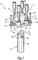
- the anchor assembly 10 comprises an anchor 12 and an insertion device 14.
- the anchor 12 comprises a body 15 defining a cavity 16.
- the anchor 12 further includes two elongate reinforcing members 18, in the form of cables, which extend through the body 15 and project outwardly therefrom on opposite sides of the body 15.
- the reinforcing members 18 are covered by the concrete.
- the reinforcing members 18 provide reinforcement to the concrete.
- An advantage of the reinforcing members 18 of the embodiment shown is that they are resiliently deformable and will spring back to their non-deformed positions in the event that, for example, a person steps on the anchor 12 before the concrete is poured over it.
- the anchor 12 is mounted on a support 20, which may be the ceiling mentioned above. Concrete is poured over the anchor 12 and across the ceiling to form a floor for the room above the ceiling. Therefore, the anchor 12 allows a user to suspend articles from the insertion device 14 inserted into the anchor 12 from the room below the ceiling.
- the body 15 comprises a holding member 22 fastened to the support 20.
- Two fastening formations in the form of lugs 24 are provided on the holding member 22.
- Each of the lugs 24 defines an aperture through which a fastener 26, such as a nail, can be driven into the support 20, thereby fastening the holding member 22 to the support 20.
- the body 15 further includes a cover member 28 mounted on the holding member 22.
- the cavity 16 is defined between the cover member 28 and the holding member 22.
- the holding member 22 defines an opening 30 through which the insertion device 14 can be inserted into the cavity 16.
- the cover member 28 includes axially projecting mounting tabs 32 receivable in sockets 34 defined around the edge of the holding member 22. The tabs 32 are received in the sockets 34 to attach the cover member 28 to the holding member 22.
- the cover member 28 has an internal surface 36 comprising an inner region 38 and an outer region 40.
- the inner region 38 is aligned with the opening 30.
- the outer region 40 of the internal surface 36 extends radially outwardly from the inner region 38 and is concavely curved.
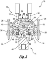
- the cover member 28 also has a cover wall 41 extending around, and from, the outer region 40 (see Figure 3 ).
- the tabs 32 extend from the cover wall 41.
- the holding member 22 has two receiving formations 42, in each of which a respective reinforcing member 18 is held.
- the holding member 22 defines opposed recesses 44, and each of the receiving formations 42 is in the form of a region of a respective one of the recesses 44.
- the receiving formations 42 are defined opposite each other by the holder 22 within the recesses 44.
- the opening 30 is defined between the receiving formations 42.
- the holding member 22 further comprises a support engaging portion for engaging the support 20.
- the recesses 44 are defined by a rim member 46, which may be in the form of a wall extending around the support engaging portion.
- the sockets 34 are defined on the opposite side of the rim member 46 to the recesses 44.
- each reinforcing member 18 extend out of the body 15 through gaps defined between the cover member 28 and the holding member 22.
- the insertion device 14 comprises a main part 48 and a securing member 49 rotatably attached to the main part 48 at an axis point 50.
- the axis point 50 is arranged at the centre of gravity of the securing member 49.
- the securing member 49 is in the form of a toggle.
- the securing member 49 is rotatably movable about the axis point 50 between securing and non-securing positions.
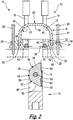
- the securing position of the securing member 49 is shown in Figures 5 and 6 .
- the non-securing position of the securing member 49 is shown in Figures 1 and 2 .
- the securing member 49 comprises two cooperating portions 52, each cooperating portion 52 having a respective tip 54.
- the two cooperating portions 52 are arranged opposite each other, with the axis point 50 arranged therebetween.
- the two tips 54 define an axis A represented by a broken line extending therebetween (see Figure 2 ).
- the axis A is offset from the axis point 50 of the securing member 49.
- Each of the two cooperating portions 52 comprises a respective first surface 56 extending from the respective tip 54.
- Each of the two cooperating portions 52 also has a respective second surface 58.
- Each of the second surfaces 58 extend from the respective first surface 56 to meet at an apex.
- the securing member 49 In order to insert the securing member 49 into the cavity 16, the securing member 49 is arranged, as shown in Figures 1 and 2 with one of the tips 54 upper most. When the insertion device 14 is inserted into the cavity 16, the tip 54 may initially engage the inner region 38 of the internal surface 36.
- Cooperation between the tip 54 and the outer region 40 of the internal surface 36 causes the securing member 49 to move the second surface 58 of the cooperating portion 52 into engagement with the inner region 38 of the internal surface 36.
- the second surface 58 of the cooperating portion 52 engages the inner region 38 of the internal surface 36 as the insertion device 14 is further moved into the cavity 16.
- the inner region 38 of the internal surface 36 of the cover member 28 cooperates with the second surface 58 of the cooperating portion 52 to urge the securing member 49 further towards the securing position.
- the cooperating portions 52 define respective concavities 60 to receive a respective one of the reinforcing members 18.
- Each concavity 60 is opposite the respective first and second surfaces 58.
- the securing member 49 engages the reinforcing members 18, which are received in the concavities 60.
- the insertion device 14 can be attached to an article to be suspended therefrom.
- the weight of the article is transmitted via the reinforcing members 18 to the concrete, thereby allowing a greater weight to be suspended than with prior art anchors.
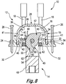
- Figures 7 and 8 show the situation where the securing member 49 is not moved fully to the securing position before it is moved into engagement with the reinforcing members 18.
- the tip 54 engages the reinforcing member 18.
- the securing member 49 is in a condition of unstable equilibrium.
- a downward force now applied to the insertion device 14 causes the securing member 49 to move either to the securing position shown in Figure 5 , or to the non-securing position shown in Figure 8 , so that the insertion device 14 is pulled downwardly, and the securing member 49 is pulled out of the cavity 16. The user can then reinsert the insertion device 14 into the cavity 16.
- an anchor assembly 10 comprising an anchor 12 and an insertion device 14 having a securing member 49 rotatably attached to the main part 48 of the insertion device 14 at the centre of gravity of the securing member 49.
- the anchor 12 includes reinforcing members 18 which are engaged by the securing member 49 to secure the insertion device 14 to the anchor 12.
- the anchor 12 includes a cover member 28 having an internal surface 36 that can cooperate with the securing member 49 to urge the securing member 49 to its securing position.
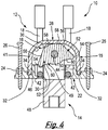
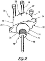
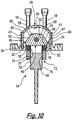
- FIGS 9 and 10 show a further anchor assembly 70, which comprises many of the same features of the anchor assembly 10 described above.
- the features of the anchor assembly 70 that are the same as the corresponding features of the anchor assembly 10 are designated with the same reference numerals.
- the anchor assembly 70 differs from the anchor assembly 10 in that the sockets 34 are defined between the rim member 46 and an outer wall 47.
- the outer wall 47 extends around the rim member 48, and around the cover member 28 when the tabs 32 of the cover member 28 are received in the sockets 34.
- the outer wall 47 extends around, and is the same height as, the cover wall 41.
- the cover wall 41 and the outer wall 47 provide protection against the ingress of concrete into the cavity 16 when the concrete is poured over the anchor 12.
- the anchor assembly 70 further includes a locking arrangement 72 comprising a locking member 74 having internal threads 76.
- the locking member 74 is in the form of nut.
- the locking arrangement 72 further includes external threads 78 formed on the main part 48.
- the insertion device 14 is inserted through the opening 30 defined in the holding member 22, and then manipulated so that the securing member 49 engages the reinforcing members 18 in the securing position.
- the locking member 74 is screwed onto the threaded main part 48 to engage the underside of the holding member 22.
- the locking member 74 is then tightened against the holding member 22 to pull the securing member 22 into tight engagement with the reinforcing members, thereby locking the securing member 22 against the reinforcing members 18
- the embodiment shown in Figures 9 and 10 provides the advantage that the possibility of the securing member 22 becoming dislodged from the reinforcing members, for example during seismic events, is significantly reduced.
Landscapes
- Engineering & Computer Science (AREA)
- Architecture (AREA)
- General Engineering & Computer Science (AREA)
- Physics & Mathematics (AREA)
- Electromagnetism (AREA)
- Civil Engineering (AREA)
- Structural Engineering (AREA)
- Mechanical Engineering (AREA)
- Joining Of Building Structures In Genera (AREA)
- Standing Axle, Rod, Or Tube Structures Coupled By Welding, Adhesion, Or Deposition (AREA)
Claims (15)
- Ankeranordnung (10), umfassend:
einen Anker (12), umfassend:einen Körper (15), der einen Hohlraum (16) definiert, wobei der Körper (15) ein Abdeckelement (28) umfasst, das sich über den Hohlraum (16) erstreckt; unddie Ankeranordnung (10) ferner Folgendes beinhaltet:eine Einführvorrichtung (14), die in den Hohlraum (16) einführbar ist, wobei die Einführvorrichtung (14) ein Sicherungselement (49) umfasst, das zwischen einer Sicherungs- und einer Nichtsicherungsposition bewegbar ist;wobei das Abdeckelement (28) mit dem Sicherungselement (49) kooperiert, um das Sicherungselement (49) in Richtung einer Sicherungsposition des Sicherungselements (49) zu drängen, wenn die Einführvorrichtung (14) in den Hohlraum (16) eingeführt wird;dadurch gekennzeichnet, dass der Anker (12) ein Verstärkungselement (18) umfasst, das sich durch den Hohlraum (16) und von dem Körper (15) nach außen erstreckt, wobei, wenn das bewegbare Sicherungselement (49) in der Sicherungsposition in dem Hohlraum (16) ist, das Sicherungselement (49) das Verstärkungselement (18) in Eingriff nehmen kann, um die Einführvorrichtung (14) an dem Anker (12) zu sichern. - Ankeranordnung (10) nach Anspruch 1, wobei der Anker (12) zwei der Verstärkungselemente (18) umfasst, die einander gegenüberliegend angeordnet sind, wobei eine Öffnung (30) zwischen den Verstärkungselementen (18) definiert ist.
- Ankeranordnung (10) nach Anspruch 1 oder 2, wobei der Körper (15) ein Halteelement (22) zum Halten der Verstärkungselemente (18) umfasst, wobei das Abdeckelement (28) an dem Halteelement (22) montierbar ist, und der Hohlraum (16) zwischen dem Abdeckelement (28) und dem Halteelement (22) definiert ist.
- Ankeranordnung (10) nach Anspruch 3, wobei das Abdeckelement (28) und das Halteelement (22) Anbringungsformationen zum Anbringen des Abdeckelements (28) an dem Halteelement (22) umfassen.
- Ankeranordnung (10) nach Anspruch 4, wobei die Anbringungsformationen eine Buchse (34) und eine Lasche (32) umfassen, die in der Buchse (34) aufnehmbar sind.
- Ankeranordnung (10) nach Anspruch 4 oder 5, wobei die Anbringungsformationen eine Vielzahl von Buchsen (34) und eine Vielzahl von Laschen (32) umfassen, die in den Buchsen (34) aufnehmbar sind.
- Ankeranordnung (10) nach einem der Ansprüche 3 bis 6, wobei das Halteelement (22) einen Basisabschnitt umfasst und das Halteelement (22) ferner eine oder mehrere Aufnahmeformationen (42) beinhaltet, um das oder jedes Verstärkungselement (18) aufzunehmen.
- Ankeranordnung (10) nach einem vorhergehenden Anspruch, wobei das Abdeckelement (28) eine Innenfläche (36) umfasst, die einen Innenbereich (38) und einen Außenbereich (40) aufweist, wobei der Innenbereich (38) auf die Öffnung (30) ausgerichtet ist.
- Ankeranordnung (10) nach einem vorhergehenden Anspruch, wobei das Sicherungselement (49) einen kooperierenden Abschnitt (52) umfasst, der eine Spitze (54), eine erste Fläche (56), die sich von der Spitze (54) erstreckt, und eine zweite Fläche (58) aufweist, die sich von der ersten Fläche (56) erstreckt;
wobei die Spitze (54) mit dem Körper (15) des Ankers (12) kooperierbar ist, um das Sicherungselement (49) in Richtung der Sicherungsposition zu drängen, wenn die Einführvorrichtung (14) in den Hohlraum (16) eingeführt wird. - Ankeranordnung (10) nach Anspruch 9, wobei die Einführvorrichtung (14) einen Hauptteil (48) umfasst, der einen Schwerpunkt aufweist, wobei das Sicherungselement (49) drehbar an dem Hauptteil (48) an dem Schwerpunkt angebracht ist.
- Ankeranordnung (10) nach Anspruch 10, wobei das Sicherungselement (49) zwei der vorgenannten kooperierenden Abschnitte (52) umfasst, wobei jeder kooperierende Abschnitt (52) eine jeweilige Spitze (54) umfasst, wobei die zwei kooperierenden Abschnitte (52) einander gegenüberliegend angeordnet sind.
- Ankeranordnung (10) nach Anspruch 11, wobei jeder der zwei kooperierenden Abschnitte (52) eine jeweilige erste Fläche (56) und eine jeweilige zweite Fläche (58) umfasst, wobei sich jede von den ersten Flächen (56) von der jeweiligen Spitze (54) erstreckt, und sich jede von den zweiten Flächen (58) von der jeweiligen ersten Fläche (56) erstreckt, wobei die Spitzen (54) der zwei kooperierenden Abschnitte (52) eine Achse definieren, die sich dazwischen erstreckt, wobei die Achse von dem Schwerpunkt des Sicherungselements (49) versetzt ist.
- Ankeranordnung (10) nach einem der Ansprüche 9 bis 12, wobei der oder jeder kooperierende Abschnitt (52) eine Konkavität (60) definiert, um das oder ein jeweiliges Verstärkungselement (18) aufzunehmen, wobei die oder jede Konkavität (60) der oder der jeweiligen ersten Fläche (56) gegenüberliegt.
- Ankeranordnung (10) nach Anspruch 9, wenn von Anspruch 1 abhängig, wobei das Abdeckelement (28) eine Innenfläche (36) umfasst, die einen Innenbereich (38) und einen Außenbereich (40) aufweist, wobei, wenn die Einführvorrichtung (14) in den Hohlraum (16) eingeführt wird, die Spitze (54) anfänglich den Innenbereich (38) der Innenfläche (36) in Eingriff nimmt, und bei weiterer Bewegung der Einführvorrichtung (14) in den Hohlraum (16) Kooperation zwischen der Spitze (54) und dem Innenbereich (38) der Innenfläche (36) bewirkt, dass sich das Sicherungselement (49) in Richtung der Sicherungsposition bewegt und die Spitze (54) den Außenbereich (40) der Innenfläche (36) in Eingriff nimmt, und Kooperation zwischen der Spitze (54) und dem Außenbereich (40) der Innenfläche (36) während der weiteren Einführung bewirkt, dass das Sicherungselement (49) die zweite Fläche (58) des kooperierenden Abschnittes (52) in Eingriff mit dem Innenbereich (38) der Innenfläche (36) bewegt, wodurch das Sicherungselement (49) weiter einwärts in Richtung der Sicherungsposition gedrängt wird, sodass der Innenbereich (38) der Innenfläche (36) mit der zweiten Fläche (58) des kooperierenden Abschnittes (52) kooperiert, um das Sicherungselement (49) in Richtung der Sicherungsposition zu drängen, wenn die Einführvorrichtung (14) weiter in den Hohlraum (16) bewegt wird.
- Ankeranordnung (10) nach Anspruch 14, wobei das Sicherungselement (49) in eine Zwischenposition zwischen der Sicherungs- und der Nichtsicherungsposition bewegbar ist, wobei, wenn sich das Sicherungselement (49) in der Zwischenposition in dem Hohlraum (16) befindet, die Spitze (54) des Sicherungselements (49) die Außenfläche des Verstärkungselements (18) in Eingriff nehmen kann.
Priority Applications (3)
| Application Number | Priority Date | Filing Date | Title |
|---|---|---|---|
| PL18746000T PL3649302T3 (pl) | 2017-07-03 | 2018-07-02 | Zespół kotwy |
| EP21167464.3A EP3868968B1 (de) | 2017-07-03 | 2018-07-02 | Anker |
| EP21167457.7A EP3865634B1 (de) | 2017-07-03 | 2018-07-02 | Einführungsvorrichtung |
Applications Claiming Priority (3)
| Application Number | Priority Date | Filing Date | Title |
|---|---|---|---|
| GBGB1710671.7A GB201710671D0 (en) | 2017-07-03 | 2017-07-03 | Anchor arrangement |
| GB1810753.2A GB2565639B (en) | 2017-07-03 | 2018-06-29 | Anchor assembly |
| PCT/GB2018/000101 WO2019008307A1 (en) | 2017-07-03 | 2018-07-02 | ANCHOR SET |
Related Child Applications (4)
| Application Number | Title | Priority Date | Filing Date |
|---|---|---|---|
| EP21167464.3A Division EP3868968B1 (de) | 2017-07-03 | 2018-07-02 | Anker |
| EP21167464.3A Division-Into EP3868968B1 (de) | 2017-07-03 | 2018-07-02 | Anker |
| EP21167457.7A Division EP3865634B1 (de) | 2017-07-03 | 2018-07-02 | Einführungsvorrichtung |
| EP21167457.7A Division-Into EP3865634B1 (de) | 2017-07-03 | 2018-07-02 | Einführungsvorrichtung |
Publications (2)
| Publication Number | Publication Date |
|---|---|
| EP3649302A1 EP3649302A1 (de) | 2020-05-13 |
| EP3649302B1 true EP3649302B1 (de) | 2021-05-26 |
Family
ID=59592709
Family Applications (3)
| Application Number | Title | Priority Date | Filing Date |
|---|---|---|---|
| EP21167457.7A Active EP3865634B1 (de) | 2017-07-03 | 2018-07-02 | Einführungsvorrichtung |
| EP21167464.3A Active EP3868968B1 (de) | 2017-07-03 | 2018-07-02 | Anker |
| EP18746000.1A Active EP3649302B1 (de) | 2017-07-03 | 2018-07-02 | Ankerkonstruktion |
Family Applications Before (2)
| Application Number | Title | Priority Date | Filing Date |
|---|---|---|---|
| EP21167457.7A Active EP3865634B1 (de) | 2017-07-03 | 2018-07-02 | Einführungsvorrichtung |
| EP21167464.3A Active EP3868968B1 (de) | 2017-07-03 | 2018-07-02 | Anker |
Country Status (13)
| Country | Link |
|---|---|
| US (3) | US11215320B2 (de) |
| EP (3) | EP3865634B1 (de) |
| JP (3) | JP7051911B2 (de) |
| AU (1) | AU2018295426B2 (de) |
| CA (1) | CA3062363A1 (de) |
| CL (1) | CL2019003715A1 (de) |
| DK (1) | DK3649302T3 (de) |
| ES (1) | ES2879363T3 (de) |
| GB (4) | GB201710671D0 (de) |
| MX (1) | MX2019014652A (de) |
| PL (1) | PL3649302T3 (de) |
| PT (1) | PT3649302T (de) |
| WO (1) | WO2019008307A1 (de) |
Families Citing this family (5)
| Publication number | Priority date | Publication date | Assignee | Title |
|---|---|---|---|---|
| US20240288115A1 (en) * | 2021-07-07 | 2024-08-29 | Gripple Limited | Anchor assembly |
| GB202109800D0 (en) * | 2021-07-07 | 2021-08-18 | Gripple Ltd | Anchor assembly |
| EP4124768A1 (de) | 2021-07-26 | 2023-02-01 | Hilti Aktiengesellschaft | Gewindestangenverbinder mit gewindelosen kontaktflächen |
| USD994478S1 (en) * | 2021-08-16 | 2023-08-08 | Gripple Limited | Anchor device |
| USD992404S1 (en) * | 2021-08-16 | 2023-07-18 | Gripple Limited | Anchor device |
Family Cites Families (24)
| Publication number | Priority date | Publication date | Assignee | Title |
|---|---|---|---|---|
| US1169635A (en) * | 1915-07-07 | 1916-01-25 | Lester A Grimes | Pipe-hanger. |
| US1684605A (en) * | 1926-11-22 | 1928-09-18 | Ewald F Techmer | Building construction |
| GB395835A (en) * | 1932-05-04 | 1933-07-27 | James Henry Bennetts | An improved device for anchoring attachments to concrete and like surfaces |
| US2164447A (en) * | 1936-09-14 | 1939-07-04 | Clarke Frederick Arthur | Coupling |
| DE920096C (de) * | 1953-03-04 | 1954-11-11 | Ingeborg Schwachula Geb Hering | Aufhaengevorrichtung fuer abzuhaengende Decken |
| US2800231A (en) * | 1954-08-17 | 1957-07-23 | Gordon M Hicks | Drain strainer |
| US2957279A (en) * | 1957-03-18 | 1960-10-25 | Lloyd L Mcnair | Ceiling suspension element |
| US3066775A (en) * | 1958-07-14 | 1962-12-04 | Wood Conversion Co | Ceiling hanger |
| NL127458C (de) * | 1963-02-26 | |||
| JPS4923683U (de) * | 1972-06-05 | 1974-02-28 | ||
| US4615514A (en) * | 1985-01-29 | 1986-10-07 | Hamlin Jerry J | Holding apparatus and method for securely positioning members to be joined by welding or the like |
| US4693389A (en) * | 1986-01-31 | 1987-09-15 | The Babcock & Wilcox Company | Reactor internals core barrel hole plug |
| US5417531A (en) * | 1994-02-09 | 1995-05-23 | Brown; Gordon A. | Locking cam anchor apparatus |
| US5702218A (en) * | 1995-12-13 | 1997-12-30 | Onofrio; Daniel | Fastener |
| DE29711251U1 (de) * | 1997-06-27 | 1998-11-12 | Emhart Inc., Newark, Del. | Halter aus Kunststoff mit verschwenkbaren Halteelementen |
| JP3702447B2 (ja) * | 2002-11-22 | 2005-10-05 | 株式会社ブレスト工業研究所 | デッキプレート用吊り金具 |
| JP2005061490A (ja) * | 2003-08-11 | 2005-03-10 | Sanko Techno Co Ltd | 中空構造物用取付け金具 |
| US6884012B2 (en) * | 2003-09-04 | 2005-04-26 | Illinois Tool Works Inc. | Heavy duty toggle bolt fastener assembly, and method of installing and removing the same |
| JP3103508U (ja) * | 2004-02-20 | 2004-08-12 | 昭進産業株式会社 | インサート取り付け具 |
| JP2005273741A (ja) * | 2004-03-24 | 2005-10-06 | Nippon Project Kk | あと施工アンカー |
| AU2004222810B1 (en) * | 2004-10-22 | 2005-04-07 | Combined Metal Fabrication Pty Ltd | A Toggle Pin |
| US20080108990A1 (en) * | 2006-11-02 | 2008-05-08 | St. Francis Medical Technologies, Inc. | Interspinous process implant having a fixed wing and a deployable wing and method of implantation |
| GB2492203B (en) * | 2011-06-21 | 2014-10-01 | Gripple Ltd | Anchor device |
| US11486432B2 (en) * | 2018-11-29 | 2022-11-01 | The Hillman Group, Inc. | Anchor assembly with toggle |
-
2017
- 2017-07-03 GB GBGB1710671.7A patent/GB201710671D0/en not_active Ceased
-
2018
- 2018-06-29 GB GB1810753.2A patent/GB2565639B/en active Active
- 2018-06-29 GB GB2010347.9A patent/GB2587478B/en active Active
- 2018-06-29 GB GB2010341.2A patent/GB2587477B/en active Active
- 2018-07-02 US US16/615,759 patent/US11215320B2/en active Active
- 2018-07-02 ES ES18746000T patent/ES2879363T3/es active Active
- 2018-07-02 PL PL18746000T patent/PL3649302T3/pl unknown
- 2018-07-02 DK DK18746000.1T patent/DK3649302T3/da active
- 2018-07-02 JP JP2019571311A patent/JP7051911B2/ja active Active
- 2018-07-02 EP EP21167457.7A patent/EP3865634B1/de active Active
- 2018-07-02 AU AU2018295426A patent/AU2018295426B2/en active Active
- 2018-07-02 PT PT187460001T patent/PT3649302T/pt unknown
- 2018-07-02 EP EP21167464.3A patent/EP3868968B1/de active Active
- 2018-07-02 WO PCT/GB2018/000101 patent/WO2019008307A1/en unknown
- 2018-07-02 EP EP18746000.1A patent/EP3649302B1/de active Active
- 2018-07-02 CA CA3062363A patent/CA3062363A1/en active Pending
- 2018-07-02 MX MX2019014652A patent/MX2019014652A/es unknown
-
2019
- 2019-12-17 CL CL2019003715A patent/CL2019003715A1/es unknown
-
2021
- 2021-11-30 US US17/537,918 patent/US11754223B2/en active Active
- 2021-11-30 US US17/537,910 patent/US11674637B2/en active Active
-
2022
- 2022-03-30 JP JP2022055400A patent/JP7375085B2/ja active Active
- 2022-03-30 JP JP2022055399A patent/JP7375084B2/ja active Active
Also Published As
Similar Documents
| Publication | Publication Date | Title |
|---|---|---|
| EP3649302B1 (de) | Ankerkonstruktion | |
| EP2723948B1 (de) | Ankervorrichtung | |
| EP3067574A1 (de) | Ein clip und eine befestigungsanordnung | |
| US6027091A (en) | Curtain clip | |
| KR101574463B1 (ko) | 천장용 캐링찬넬 고정행거 | |
| US4988249A (en) | Method for fastening an attachment or suspension device and a device for carrying out the method | |
| WO2005113202A1 (en) | Conduit anchor | |
| JPH02180304A (ja) | ハンガーブラケット | |
| US20240288115A1 (en) | Anchor assembly | |
| EP0733812B1 (de) | Blindbefestigungsvorrichtung | |
| CN117597524A (zh) | 锚固组件 | |
| JPH11141112A (ja) | 建物用化粧カバーの取付構造 | |
| KR20000006794A (ko) | 콘크리트 못의 부착물을 위한 고정장치 | |
| JPH11155723A (ja) | 壁ハンガー |
Legal Events
| Date | Code | Title | Description |
|---|---|---|---|
| STAA | Information on the status of an ep patent application or granted ep patent |
Free format text: STATUS: UNKNOWN |
|
| STAA | Information on the status of an ep patent application or granted ep patent |
Free format text: STATUS: THE INTERNATIONAL PUBLICATION HAS BEEN MADE |
|
| PUAI | Public reference made under article 153(3) epc to a published international application that has entered the european phase |
Free format text: ORIGINAL CODE: 0009012 |
|
| STAA | Information on the status of an ep patent application or granted ep patent |
Free format text: STATUS: REQUEST FOR EXAMINATION WAS MADE |
|
| 17P | Request for examination filed |
Effective date: 20200108 |
|
| AK | Designated contracting states |
Kind code of ref document: A1 Designated state(s): AL AT BE BG CH CY CZ DE DK EE ES FI FR GB GR HR HU IE IS IT LI LT LU LV MC MK MT NL NO PL PT RO RS SE SI SK SM TR |
|
| AX | Request for extension of the european patent |
Extension state: BA ME |
|
| DAV | Request for validation of the european patent (deleted) | ||
| DAX | Request for extension of the european patent (deleted) | ||
| GRAP | Despatch of communication of intention to grant a patent |
Free format text: ORIGINAL CODE: EPIDOSNIGR1 |
|
| STAA | Information on the status of an ep patent application or granted ep patent |
Free format text: STATUS: GRANT OF PATENT IS INTENDED |
|
| INTG | Intention to grant announced |
Effective date: 20210317 |
|
| GRAS | Grant fee paid |
Free format text: ORIGINAL CODE: EPIDOSNIGR3 |
|
| GRAA | (expected) grant |
Free format text: ORIGINAL CODE: 0009210 |
|
| STAA | Information on the status of an ep patent application or granted ep patent |
Free format text: STATUS: THE PATENT HAS BEEN GRANTED |
|
| RBV | Designated contracting states (corrected) |
Designated state(s): AL AT BE BG CH CY CZ DE DK EE ES FI FR GR HR HU IE IS IT LI LT LU LV MC MK MT NL NO PL PT RO RS SE SI SK SM TR |
|
| AK | Designated contracting states |
Kind code of ref document: B1 Designated state(s): AL AT BE BG CH CY CZ DE DK EE ES FI FR GR HR HU IE IS IT LI LT LU LV MC MK MT NL NO PL PT RO RS SE SI SK SM TR |
|
| REG | Reference to a national code |
Ref country code: CH Ref legal event code: EP |
|
| REG | Reference to a national code |
Ref country code: DE Ref legal event code: R096 Ref document number: 602018017751 Country of ref document: DE |
|
| REG | Reference to a national code |
Ref country code: AT Ref legal event code: REF Ref document number: 1396351 Country of ref document: AT Kind code of ref document: T Effective date: 20210615 |
|
| REG | Reference to a national code |
Ref country code: DK Ref legal event code: T3 Effective date: 20210618 |
|
| REG | Reference to a national code |
Ref country code: IE Ref legal event code: FG4D |
|
| REG | Reference to a national code |
Ref country code: PT Ref legal event code: SC4A Ref document number: 3649302 Country of ref document: PT Date of ref document: 20210628 Kind code of ref document: T Free format text: AVAILABILITY OF NATIONAL TRANSLATION Effective date: 20210621 |
|
| REG | Reference to a national code |
Ref country code: NL Ref legal event code: FP |
|
| REG | Reference to a national code |
Ref country code: SE Ref legal event code: TRGR |
|
| REG | Reference to a national code |
Ref country code: NO Ref legal event code: T2 Effective date: 20210526 |
|
| REG | Reference to a national code |
Ref country code: LT Ref legal event code: MG9D |
|
| PG25 | Lapsed in a contracting state [announced via postgrant information from national office to epo] |
Ref country code: FI Free format text: LAPSE BECAUSE OF FAILURE TO SUBMIT A TRANSLATION OF THE DESCRIPTION OR TO PAY THE FEE WITHIN THE PRESCRIBED TIME-LIMIT Effective date: 20210526 Ref country code: LT Free format text: LAPSE BECAUSE OF FAILURE TO SUBMIT A TRANSLATION OF THE DESCRIPTION OR TO PAY THE FEE WITHIN THE PRESCRIBED TIME-LIMIT Effective date: 20210526 Ref country code: HR Free format text: LAPSE BECAUSE OF FAILURE TO SUBMIT A TRANSLATION OF THE DESCRIPTION OR TO PAY THE FEE WITHIN THE PRESCRIBED TIME-LIMIT Effective date: 20210526 Ref country code: BG Free format text: LAPSE BECAUSE OF FAILURE TO SUBMIT A TRANSLATION OF THE DESCRIPTION OR TO PAY THE FEE WITHIN THE PRESCRIBED TIME-LIMIT Effective date: 20210826 |
|
| REG | Reference to a national code |
Ref country code: ES Ref legal event code: FG2A Ref document number: 2879363 Country of ref document: ES Kind code of ref document: T3 Effective date: 20211122 |
|
| PG25 | Lapsed in a contracting state [announced via postgrant information from national office to epo] |
Ref country code: LV Free format text: LAPSE BECAUSE OF FAILURE TO SUBMIT A TRANSLATION OF THE DESCRIPTION OR TO PAY THE FEE WITHIN THE PRESCRIBED TIME-LIMIT Effective date: 20210526 Ref country code: RS Free format text: LAPSE BECAUSE OF FAILURE TO SUBMIT A TRANSLATION OF THE DESCRIPTION OR TO PAY THE FEE WITHIN THE PRESCRIBED TIME-LIMIT Effective date: 20210526 Ref country code: IS Free format text: LAPSE BECAUSE OF FAILURE TO SUBMIT A TRANSLATION OF THE DESCRIPTION OR TO PAY THE FEE WITHIN THE PRESCRIBED TIME-LIMIT Effective date: 20210926 Ref country code: GR Free format text: LAPSE BECAUSE OF FAILURE TO SUBMIT A TRANSLATION OF THE DESCRIPTION OR TO PAY THE FEE WITHIN THE PRESCRIBED TIME-LIMIT Effective date: 20210827 |
|
| PG25 | Lapsed in a contracting state [announced via postgrant information from national office to epo] |
Ref country code: RO Free format text: LAPSE BECAUSE OF FAILURE TO SUBMIT A TRANSLATION OF THE DESCRIPTION OR TO PAY THE FEE WITHIN THE PRESCRIBED TIME-LIMIT Effective date: 20210526 Ref country code: SM Free format text: LAPSE BECAUSE OF FAILURE TO SUBMIT A TRANSLATION OF THE DESCRIPTION OR TO PAY THE FEE WITHIN THE PRESCRIBED TIME-LIMIT Effective date: 20210526 Ref country code: EE Free format text: LAPSE BECAUSE OF FAILURE TO SUBMIT A TRANSLATION OF THE DESCRIPTION OR TO PAY THE FEE WITHIN THE PRESCRIBED TIME-LIMIT Effective date: 20210526 Ref country code: SK Free format text: LAPSE BECAUSE OF FAILURE TO SUBMIT A TRANSLATION OF THE DESCRIPTION OR TO PAY THE FEE WITHIN THE PRESCRIBED TIME-LIMIT Effective date: 20210526 |
|
| REG | Reference to a national code |
Ref country code: DE Ref legal event code: R097 Ref document number: 602018017751 Country of ref document: DE |
|
| PLBE | No opposition filed within time limit |
Free format text: ORIGINAL CODE: 0009261 |
|
| STAA | Information on the status of an ep patent application or granted ep patent |
Free format text: STATUS: NO OPPOSITION FILED WITHIN TIME LIMIT |
|
| PG25 | Lapsed in a contracting state [announced via postgrant information from national office to epo] |
Ref country code: MC Free format text: LAPSE BECAUSE OF FAILURE TO SUBMIT A TRANSLATION OF THE DESCRIPTION OR TO PAY THE FEE WITHIN THE PRESCRIBED TIME-LIMIT Effective date: 20210526 |
|
| 26N | No opposition filed |
Effective date: 20220301 |
|
| PG25 | Lapsed in a contracting state [announced via postgrant information from national office to epo] |
Ref country code: IS Free format text: LAPSE BECAUSE OF FAILURE TO SUBMIT A TRANSLATION OF THE DESCRIPTION OR TO PAY THE FEE WITHIN THE PRESCRIBED TIME-LIMIT Effective date: 20210926 Ref country code: LU Free format text: LAPSE BECAUSE OF NON-PAYMENT OF DUE FEES Effective date: 20210702 Ref country code: AL Free format text: LAPSE BECAUSE OF FAILURE TO SUBMIT A TRANSLATION OF THE DESCRIPTION OR TO PAY THE FEE WITHIN THE PRESCRIBED TIME-LIMIT Effective date: 20210526 |
|
| REG | Reference to a national code |
Ref country code: AT Ref legal event code: UEP Ref document number: 1396351 Country of ref document: AT Kind code of ref document: T Effective date: 20210526 |
|
| P01 | Opt-out of the competence of the unified patent court (upc) registered |
Effective date: 20230523 |
|
| PG25 | Lapsed in a contracting state [announced via postgrant information from national office to epo] |
Ref country code: CY Free format text: LAPSE BECAUSE OF FAILURE TO SUBMIT A TRANSLATION OF THE DESCRIPTION OR TO PAY THE FEE WITHIN THE PRESCRIBED TIME-LIMIT Effective date: 20210526 |
|
| PG25 | Lapsed in a contracting state [announced via postgrant information from national office to epo] |
Ref country code: HU Free format text: LAPSE BECAUSE OF FAILURE TO SUBMIT A TRANSLATION OF THE DESCRIPTION OR TO PAY THE FEE WITHIN THE PRESCRIBED TIME-LIMIT; INVALID AB INITIO Effective date: 20180702 |
|
| PGFP | Annual fee paid to national office [announced via postgrant information from national office to epo] |
Ref country code: NO Payment date: 20230720 Year of fee payment: 6 Ref country code: IT Payment date: 20230731 Year of fee payment: 6 Ref country code: IE Payment date: 20230726 Year of fee payment: 6 Ref country code: ES Payment date: 20230821 Year of fee payment: 6 Ref country code: CH Payment date: 20230801 Year of fee payment: 6 Ref country code: AT Payment date: 20230718 Year of fee payment: 6 |
|
| PGFP | Annual fee paid to national office [announced via postgrant information from national office to epo] |
Ref country code: SE Payment date: 20230724 Year of fee payment: 6 Ref country code: FR Payment date: 20230720 Year of fee payment: 6 Ref country code: DK Payment date: 20230724 Year of fee payment: 6 Ref country code: DE Payment date: 20230720 Year of fee payment: 6 Ref country code: BE Payment date: 20230719 Year of fee payment: 6 |
|
| PG25 | Lapsed in a contracting state [announced via postgrant information from national office to epo] |
Ref country code: MK Free format text: LAPSE BECAUSE OF FAILURE TO SUBMIT A TRANSLATION OF THE DESCRIPTION OR TO PAY THE FEE WITHIN THE PRESCRIBED TIME-LIMIT Effective date: 20210526 |
|
| PGFP | Annual fee paid to national office [announced via postgrant information from national office to epo] |
Ref country code: CZ Payment date: 20240626 Year of fee payment: 7 |
|
| PGFP | Annual fee paid to national office [announced via postgrant information from national office to epo] |
Ref country code: PL Payment date: 20240625 Year of fee payment: 7 Ref country code: PT Payment date: 20240626 Year of fee payment: 7 |
|
| PGFP | Annual fee paid to national office [announced via postgrant information from national office to epo] |
Ref country code: TR Payment date: 20240628 Year of fee payment: 7 |
|
| PGFP | Annual fee paid to national office [announced via postgrant information from national office to epo] |
Ref country code: NL Payment date: 20240722 Year of fee payment: 7 |