EP3648270A1 - Kabelbearbeitungsvorrichtung - Google Patents
Kabelbearbeitungsvorrichtung Download PDFInfo
- Publication number
- EP3648270A1 EP3648270A1 EP18204135.0A EP18204135A EP3648270A1 EP 3648270 A1 EP3648270 A1 EP 3648270A1 EP 18204135 A EP18204135 A EP 18204135A EP 3648270 A1 EP3648270 A1 EP 3648270A1
- Authority
- EP
- European Patent Office
- Prior art keywords
- cable
- good
- processing device
- cables
- bad
- Prior art date
- Legal status (The legal status is an assumption and is not a legal conclusion. Google has not performed a legal analysis and makes no representation as to the accuracy of the status listed.)
- Granted
Links
Images




Classifications
-
- H—ELECTRICITY
- H01—ELECTRIC ELEMENTS
- H01B—CABLES; CONDUCTORS; INSULATORS; SELECTION OF MATERIALS FOR THEIR CONDUCTIVE, INSULATING OR DIELECTRIC PROPERTIES
- H01B13/00—Apparatus or processes specially adapted for manufacturing conductors or cables
-
- H—ELECTRICITY
- H02—GENERATION; CONVERSION OR DISTRIBUTION OF ELECTRIC POWER
- H02G—INSTALLATION OF ELECTRIC CABLES OR LINES, OR OF COMBINED OPTICAL AND ELECTRIC CABLES OR LINES
- H02G1/00—Methods or apparatus specially adapted for installing, maintaining, repairing or dismantling electric cables or lines
- H02G1/12—Methods or apparatus specially adapted for installing, maintaining, repairing or dismantling electric cables or lines for removing insulation or armouring from cables, e.g. from the end thereof
- H02G1/1202—Methods or apparatus specially adapted for installing, maintaining, repairing or dismantling electric cables or lines for removing insulation or armouring from cables, e.g. from the end thereof by cutting and withdrawing insulation
- H02G1/1248—Machines
-
- H—ELECTRICITY
- H01—ELECTRIC ELEMENTS
- H01R—ELECTRICALLY-CONDUCTIVE CONNECTIONS; STRUCTURAL ASSOCIATIONS OF A PLURALITY OF MUTUALLY-INSULATED ELECTRICAL CONNECTING ELEMENTS; COUPLING DEVICES; CURRENT COLLECTORS
- H01R43/00—Apparatus or processes specially adapted for manufacturing, assembling, maintaining, or repairing of line connectors or current collectors or for joining electric conductors
- H01R43/04—Apparatus or processes specially adapted for manufacturing, assembling, maintaining, or repairing of line connectors or current collectors or for joining electric conductors for forming connections by deformation, e.g. crimping tool
- H01R43/048—Crimping apparatus or processes
- H01R43/052—Crimping apparatus or processes with wire-feeding mechanism
-
- H—ELECTRICITY
- H01—ELECTRIC ELEMENTS
- H01R—ELECTRICALLY-CONDUCTIVE CONNECTIONS; STRUCTURAL ASSOCIATIONS OF A PLURALITY OF MUTUALLY-INSULATED ELECTRICAL CONNECTING ELEMENTS; COUPLING DEVICES; CURRENT COLLECTORS
- H01R43/00—Apparatus or processes specially adapted for manufacturing, assembling, maintaining, or repairing of line connectors or current collectors or for joining electric conductors
- H01R43/28—Apparatus or processes specially adapted for manufacturing, assembling, maintaining, or repairing of line connectors or current collectors or for joining electric conductors for wire processing before connecting to contact members, not provided for in groups H01R43/02 - H01R43/26
Definitions
- the present disclosure relates to a cable processing device which outputs a cable or a plurality of cables for removal after an assembly process has taken place.
- Cable processing devices or cable processing devices are usually equipped with a cable tray, which are designed, for example, in the form of a cable tray or removal tray.
- the cable processing device produces a plurality of cables that together form a wireless (a cable assembly). For example, a certain number of cables of the same type or groups of cables of the same type form a cordless.
- Such quality requirements include insufficiently stripped conductor ends, individual strands that have missed the intended opening of a termination piece (for example a plug contact, a ferrule or the like), crooked or insufficiently crimped connectors etc.
- a prefabricated cable that does not meet such a quality requirement is generally referred to as a bad cable and is usually disposed of as waste. Accordingly, a prefabricated cable that meets the quality requirement is generally referred to as a good cable.
- Cable processing devices are increasingly equipped with quality monitoring systems, the various process steps such. B. stripping and crimping, monitor and detect such bad cables. For this purpose, a quality monitoring system can observe, for example, that the stripping process and / or the crimping process for a component to be assembled is faulty, and then make an assessment that the cable currently being output is a bad cable.
- the quality monitoring system detects a bad cable
- the bad cable is caused to be marked so that it can be recognized by an operator. For example, if a contact is crimped incorrectly, this contact is caused to be disconnected again. Alternatively, if the conductor end is stripped incorrectly, for example, no contact is crimped on.
- a cable processing device comprises at least one processing unit for assembling a cable.
- the cable processing device also comprises a sorting device which can be controlled with a selection signal for outputting a cable taken over from the processing unit at least on a first side or on a second side according to the selection signal.
- a processing unit, or assembly unit is provided, for example, in the form of a stripping device, a crimping press device or the like, but is not limited to this.
- the selection signal is generated externally, for example, or the selection signal is generated internally by a suitable component of the cable processing device.
- the adopted cable is output on the first side or on the second side according to the selection signal.
- the sorting device always takes exactly one cable, typically a prefabricated cable, from the processing unit, whereupon the selection for this cable takes place in accordance with the selection signal. After the selection The sorting device takes over the next one cable from the processing unit, whereupon the selection for this cable takes place, etc.
- the selection that is made by activating the sorting device with the selection signal can, for example, cause good cables to always be output on one side (for example always on the first side) and bad cables always on the other side (for example always on the second side) ) are output. This can simplify the provision of a flawless wireless (a wireless that contains only good cables).
- the sorting device is a multiple trough that is rotatable about an axis of rotation.
- the axis of rotation runs approximately parallel to the cable axis of the adopted cable. The rotation around the axis of rotation takes place according to the selection signal.
- the sorting process can be accelerated with a selectively rotatable multiple trough.
- the sorting process itself can be carried out easily and safely in this way.
- the multiple tub includes two or more tub chambers.
- the multiple tub has three tub chambers of approximately the same size. Basin chambers of approximately the same size have approximately the same volume. With the rotatable mounting and approximately the same size tub chambers, in particular three tub chambers of approximately the same size, there can be the advantage that a central mounting is possible in the center of gravity, which reduces imbalance, etc.
- the cable processing device also includes a selection device.
- the selection device is set up to output the selection signal to the sorting device, depending on a detected assembly quality of the cable.
- An assembly quality as used herein, is, for example, a distinction between a good cable and a bad cable, as explained above. However, it is also possible to take intermediate qualities into account and to define one or more threshold values, depending on which the selection signal is generated.
- the cable processing device can comprise a detection unit for detection.
- the detection unit is set up to detect the quality of the cable assembly.
- a monitoring device for the crimping force integrated in the crimping press device mentioned above is a common example of a detection unit.
- the monitoring device is set up to use a force sensor to record the force curve when performing a crimping process (a pressing process of the stripped cable end with the contact) by means of the crimping press device and to compare it with a target curve. Process errors can be identified on the basis of the comparison. B. missing strands in contact.
- an image acquisition unit e.g. a digital camera
- an image evaluation unit is provided as the detection unit, wherein the image acquisition unit transmits an image of a representative area of a prefabricated cable recorded continuously or at fixed or definable time intervals to the image evaluation unit.
- the image evaluation unit executes, for example, an image evaluation software which uses the transmitted image to evaluate or detect the Carries out the quality of the underlying cable.
- the assembly quality of the cable comprises a sufficient quality of the cable, in which the cable is classified as a good cable, and it also comprises an insufficient quality of the cable, in which the cable is classified as a bad cable. It can be provided here that a good cable transfer device is arranged on the first side and a bad cable transfer device is arranged on the second side.
- a takeover device means a component or an element or a plurality of components or elements which are designed to take over a good cable or a bad cable and, if appropriate, to store it for a certain period of time.
- the good cable transfer device has a good cable removal trough. With the configuration of the good cable removal trough, an operator (or also an automatic removal device, for example a removal robot) is enabled to remove the good cable or cables contained in the good cable removal trough.
- the good cable take-over device includes a good cable storage tray and the described good cable removal tray.
- the good cable storage trough is designed to accept good cables from a plurality of cables contained in a wireless.
- the good cable storage tray is configured for transferring the plurality of cables into the good cable removal tray if the quantity of the plurality of cables corresponds to the size of the wireless cable. It is then possible for the cable tray to be removed can have exactly two states: Either it is empty, or there is exactly the amount of good cables available in the good cable trough that corresponds to a wireless one.
- the good cable storage trough prefferably be designed such that it can be tilted and / or pivoted relative to the removal trough in such a way that the plurality of cables slides into the good cable removal trough during transfer.
- This provides a particularly simple way of transferring cables from the good cable storage tray to the good cable removal tray.
- the tilting or pivoting is preferably carried out automatically.
- the tilting or pivoting is particularly preferably carried out by automatic control of a pneumatic actuator.
- the bad cable take-over device comprises a bad cable removal trough.
- an operator or also an automatic removal device, for example a removal robot is enabled to remove the bad cable (s) contained in the bad cable removal trough.
- the good cable removal trough is designed in such a way that it comprises a movable part and a fixed part.
- the moving part can be moved lengthways.
- the movable part is automatically longitudinally displaceable.
- the movable part is preferably pneumatically longitudinally displaceable.
- the bad cable removal trough is designed such that it comprises a movable part and a fixed part.
- the moving part can be moved lengthways.
- the moving part can be automatically moved lengthways.
- the movable part is preferably pneumatically longitudinally displaceable.
- the cable processing device also has a conveyor belt for transferring the cable from the at least one processing unit to the sorting device.
- Fig. 1 shows a schematic sectional view of a conventional cable processing device 100.
- the cable processing device 100 has a conveyor belt 20 which is driven by a drive motor 10 and on which assembled cables are transported from one or more processing stations of the cable processing device in the direction of a storage tray 30.
- the storage tray 30 can be pivoted about a pivot axis 40 by means of a controllable pivot cylinder 41, as indicated by the arrow. Good cables contained in the storage tray at a certain time, but also bad cables (not shown) fall or slide into the removal tray 50 during a pivoting movement and can be removed there.
- the buffer formed by the storage tray 30 enables the collection of a predetermined or determinable number of finished cables.
- a wireless or production lot is complete.
- the produced wireless is automatically transferred to the removal tray 50 by the described pivoting movement of the storage tray 30 or after confirmation by an operator, where it can be removed, for example, by hand, while the cable processing device 100 produces the next production batch and the cables belonging to this next production batch in the storage tray 30 pivoted upwards again.
- the conveyor belt 20 ensures that the cables remain stretched when being transported into the cable processing device 100 and during the processing of the trailing end (downstream end) of the cable. If this trailing end of the cable is dropped next to the conveyor belt, it slips in combination with its own weight the transport movement of the conveyor belt sideways from the conveyor belt 20 and falls into the storage tray 30.
- Fig. 2 is analogous to in a side sectional view Fig. 1 a cable processing device 100 according to an embodiment of the present disclosure.
- the cable processing device 100 according to the embodiment in turn has a conveyor belt 20 which is moved by a drive motor (not shown).
- a storage tray 30 can be pivoted about a pivot axis 40 by means of a pneumatically operated pivoting cylinder 41 approximately along the arrow direction of the arrow on the storage tray 30, so that cables located in the storage tray slide into a removal tray 50.
- Fig. 1 10 shows the cable processing device 100 according to the embodiment in FIG Fig. 2 a sorting device 60, which can be rotated in pulses or in sections about an axis of rotation D approximately parallel to the cable axis according to a selection signal.
- the sorting device 60 has a first trough chamber 1, a second trough chamber 2 and a third trough chamber 3, which are approximately of the same size (ie are of approximately the same volume) and are separated from one another by partitions. The partitions divide approximately at 120 ° intervals.
- a manufactured (prefabricated) cable comes from the conveyor belt 20 into a trough of the sorting device 60.
- the sorting device 60 receives a command from a machine control (for example a selection device 80) to either counterclockwise by approximately 120 ° or counterclockwise by approximately 120 ° Turn clockwise around the axis of rotation D.
- a machine control for example a selection device 80
- the cable in the tub chamber 1 in Fig. 2 would like it, after a rotation of about 120 ° counterclockwise where in Fig. 2 the tub chamber 2 is shown. Accordingly, the cable would be located in a clockwise direction where it is in Fig. 2 the tub chamber 3 is shown.
- the cable With a counterclockwise rotation, the cable accordingly falls or slips into the storage tray 30, which is located on a side A with respect to the sorting device 60. With a clockwise rotation, the cable falls or slips into another storage tray 70 located on the opposite side B.
- the storage tray 30 on side A serves as a good cable storage tray, while the storage tray 70 on side B serves as a bad cable storage tray.
- the good cable storage trough 30 pivots about the pivot axis by appropriate actuation of the pneumatic cylinder 41, so that the wireless is emptied into the good cable removal trough 50.
- the cable processing device 100 can produce the next lot.
- the bad cables land in the bad cable storage tray 70 accordingly. If there is still a lot in the good cable removal tray 50 after the lot size has been reached, the machine stops so that an operator can remove the cables.
- the sorting device 60 does not need to turn back after transferring the cable to side A or side B, but can directly the next cable in the conveyor belt 20 then facing Take up the tub chamber. As a result, the sorting process does not reduce the machine's time output.
- the selection device 80 is connected directly to the sorting device 60.
- the present disclosure is not limited to this, and there may also be an indirect connection between these elements, for example via an intermediate machine control (not shown).
- the selection device 80 it is also possible for the selection device 80 to be part of such a machine control.
- the selection device 80 outputs a selection signal S to the sorting device 60, which corresponds to an instruction for rotating the sorting device 60 either in the direction of the side A or in the direction of the side B.
- the selection time is, for example, a time-based, recurring time in the processing cycle of the cable processing device 100.
- the timing can be fixed or also variable.
- a variable cycle can be determined, for example, depending on the case, in that it is recognized that the takeover process of a taken over cable into the tub chamber facing the conveyor belt 20 is completed.
- the selection device 80 is also connected to a detection unit 90.
- the detection unit 90 has, for example, a digital camera or the like for capturing an image of the taken over cable, as well as a possibility for image processing of an image captured by the digital camera. It is also common for the detection unit 90 to include a force sensor (not shown) for crimp force monitoring, the detection unit 90 is set up to use the force sensor to compare a force profile when performing a crimping process with a target profile and to transmit the comparison or the comparison result to the selection device 80.
- the detection unit 90 or the selection device 80 connected to it detects whether the cable to be taken over, which will next be taken over into the tub chamber facing the conveyor belt 20, represents a good cable or a bad cable.
- the detection unit 90 or the selection device 80 connected to it detects whether the taken over cable, which was taken over into the tub chamber facing the conveyor belt 20, represents a good cable or a bad cable.
- the selection signal S is generated in accordance with the result of the detection.
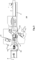
- FIG. 3 A top view of cable processing apparatus 100 is shown for purposes of illustration.
- the cable processing device 100 In order to assemble the cable, which is drawn in along a cable pull-in axis R and transported by a cable feeder 106 through the processing stations, the cable processing device 100 has a first crimping press 101, a second crimping press 102, a cutter head 105 for stripping, a first swivel unit 103 and a second Swivel unit 104 on.
- a good cable takeover device 31 which includes, for example, the good cable storage tray 30, is on the right in Fig. 3 to recognize. Details of the basic function of the cable processing device 100 can be found, for example, in the publication EP 2 442 413 A1 which is incorporated herein by reference.
- Fig. 4 shows a perspective view of the cable storage of the cable processing device according to the embodiment, while Fig. 5 a schematic perspective view of the cable storage Fig. 4 shows from a different perspective.
- the good cable take-over device 31 comprises a good cable removal trough 50, which has a movable part 50a and a fixed part 50b.
- the movable part 50a of the two-part good cable removal trough 50 can be displaceable longitudinally, for example by means of a pneumatic cylinder (not shown), so that short cables can be transported out of the part of the machine which is difficult to access under a protective hood and can also be removed while the machine is running. Even if it is not shown, this principle can in principle also be applied to the bad cable removal trough 70.
- the sorting device 60 in the embodiment is an elongated body which is rotatable overall about the axis of rotation D.
- the head of the pivot cylinder 41 is attached to the good cable storage tray 30 such that the good cable storage tray 30 outputs the good cables contained therein into the good cable removal tray 50 during a pivoting movement by means of the pivot cylinder 41.
Landscapes
- Engineering & Computer Science (AREA)
- Manufacturing & Machinery (AREA)
- Specific Conveyance Elements (AREA)
- Sorting Of Articles (AREA)
- Branching, Merging, And Special Transfer Between Conveyors (AREA)
- Discharge Of Articles From Conveyors (AREA)
- Testing Of Short-Circuits, Discontinuities, Leakage, Or Incorrect Line Connections (AREA)
- Insulated Conductors (AREA)
- Laying Of Electric Cables Or Lines Outside (AREA)
- Manufacturing Of Electrical Connectors (AREA)
Abstract
Description
- Die vorliegende Offenbarung betrifft eine Kabelbearbeitungsvorrichtung, welche ein Kabel oder eine Mehrzahl von Kabeln nach einem erfolgten Konfektioniervorgang zur Entnahme ausgibt.
- Kabelbearbeitungsvorrichtungen oder Kabelbearbeitungsvorrichtungen sind üblicherweise mit einer Kabelablage ausgestattet, die beispielsweise in der Form einer Kabelwanne oder Entnahmewanne ausgebildet sind. Typischerweise produziert die Kabelbearbeitungsvorrichtung eine Mehrzahl von Kabeln, die zusammen ein Kabellos (eine Kabelzusammenstellung) bilden. Beispielsweise bildet eine bestimmte Anzahl von gleichartig konfektionierten Kabeln oder von jeweils gleichartig konfektionierten Gruppen von Kabeln ein Kabellos.
- Verschiedene Prozessschritte bzw. Konfektionierungsschritte für ein zu konfektionierendes Kabel, wie z. B. ein Abisolierschritt, ein Crimpschritt und dergleichen, können ggf. fehlerhaft ausgeführt werden und zur Konfektionierung eines Kabels führen, das vorgegebenen oder vorgebbaren Qualitätsanforderungen nicht genügt.
- Beispiele für solche Qualitätsanforderungen umfassen unzureichend abisolierte Leiterenden, einzelne Litzen, die die Sollöffnung eines Abschlussstücks verfehlt haben (beispielsweise einem Steckkontakt, einer Aderendhülse oder dergleichen), schief oder unzureichend fest angecrimpte Steckverbinder usw.
- Ein konfektioniertes Kabel, das einer solchen Qualitätsanforderung nicht genügt, wird allgemein als Schlechtkabel bezeichnet und in der Regel als Ausschuss entsorgt. Entsprechend wird ein konfektioniertes Kabel, das der Qualitätsanforderung genügt, allgemein als Gutkabel bezeichnet. Kabelbearbeitungsvorrichtungen sind zunehmend mit Qualitätsüberwachungssystemen ausgestattet, die verschiedene Prozessschritte, wie z. B. das Abisolieren und das Crimpen, überwachen und solche Schlechtkabel erkennen können. Ein Qualitätsüberwachungssystem kann hierzu beispielsweise beobachten, dass der Abisoliervorgang und/oder der Crimpvorgang für ein zu konfektionierendes fehlerhaft verläuft, und daraufhin eine dahingehende Bewertung treffen, dass das aktuell ausgegebene Kabel ein Schlechtkabel ist.
- Ein herkömmlicher Ansatz ist im Folgenden beschrieben: Wenn das Qualitätsüberwachungssystem ein Schlechtkabel erkennt, wird veranlasst, dass das Schlechtkabel für eine Bedienperson erkennbar markiert wird. Beispielsweise wird bei einem fehlerhaft angecrimpten Kontakt veranlasst, dass dieser Kontakt wieder abgetrennt wird. Alternativ wird beispielsweise bei einem fehlerhaft abisolierten Leiterende veranlasst, dass kein Kontakt angecrimpt wird.
- Auch wenn für ein solches Schlechtkabel automatisiert ein fehlerfreies Kabel nachproduziert werden kann, gelangt das Schlechtkabel dennoch in die Kabelablage und muss von der Bedienperson aussortiert werden. Wenn die Bedienperson ein Schlechtkabel übersieht, bleibt dieses Schlechtkabel ein Teil des Kabelloses.
- Es besteht Bedarf an einer Kabelbearbeitungsvorrichtung, bei welcher der Vorgang zum Bereitstellen einer fehlerfreien Kabelloses verbessert ist. Die Aufgabe wird gelöst durch eine Kabelbearbeitungsvorrichtung gemäss Anspruch 1. Vorteilhafte Weiterbildungen sind in den abhängigen Ansprüchen angegeben. Es versteht sich, dass einzelne hierin beschriebene Ausführungsformen, Aspekte und/oder Merkmale miteinander kombiniert werden können oder entsprechend weggelassen werden können, wenn angemessen.
- Gemäss einem Aspekt wird eine Kabelbearbeitungsvorrichtung bereitgestellt. Die Kabelbearbeitungsvorrichtung umfasst mindestens eine Bearbeitungseinheit zur Konfektionierung eines Kabels. Die Kabelbearbeitungsvorrichtung umfasst ausserdem eine mit einem Selektionssignal ansteuerbare Sortiereinrichtung zum Ausgeben eines aus der Bearbeitungseinheit übernommenen Kabels zumindest auf einer ersten Seite oder auf einer zweiten Seite gemäss dem Selektionssignal.
- Eine Bearbeitungseinheit, oder Konfektionierungseinheit, ist beispielsweise in Form einer Abisolierungseinrichtung, einer Crimppresseinrichtung oder dergleichen bereitgestellt, aber darauf nicht beschränkt. Das Selektionssignal wird beispielsweise extern erzeugt, oder das Selektionssignal wird von einer geeigneten Komponente der Kabelbearbeitungsvorrichtung intern erzeugt. Typischerweise erfolgt die Ausgabe des übernommenen Kabels gemäss dem Selektionssignal entweder auf der ersten Seite oder auf der zweiten Seite. Besonders bevorzugt übernimmt die Sortiereinrichtung immer genau ein Kabel, typischerweise konfektioniertes Kabel, aus der Bearbeitungseinheit, woraufhin die Selektion für dieses übernommene Kabel gemäss dem Selektionssignal erfolgt. Im Anschluss an die Selektion übernimmt die Sortiereinrichtung das nächste eine Kabel aus der Bearbeitungseinheit, woraufhin die Selektion für dieses übernommene Kabel erfolgt, usw.
- Durch die Selektion, die durch Ansteuern der Sortiereinrichtung mit dem Selektionssignal erfolgt, kann beispielsweise veranlasst werden, dass Gutkabel immer auf der einen Seite (beispielsweise immer auf der ersten Seite) ausgegeben werden und Schlechtkabel immer auf der anderen Seite (beispielsweise immer auf der zweiten Seite) ausgegeben werden. Dies kann die Bereitstellung eines fehlerfreien Kabelloses (eines Kabelloses, das nur Gutkabel enthält) vereinfachen.
- Bei Ausführungsformen ist die Sortiereinrichtung eine Mehrfachwanne, die um eine Drehachse drehbar ist. Die Drehachse verläuft ungefähr parallel zur Kabelachse des übernommenen Kabels. Die Drehung um die Drehachse erfolgt gemäss dem Selektrionssignal.
- Mit einer selektiv drehbaren Mehrfachwanne kann der Sortiervorgang beschleunigt werden. Der Sortiervorgang selbst ist auf diese Weise einfach und sicher ausführbar.
- Bei Ausführungsformen umfasst die Mehrfachwanne zwei oder mehr Wannenkammern. Gemäss einer vorteilhaften Ausbildung weist die Mehrfachwanne drei etwa gleich grosse Wannenkammern auf. In etwa gleich grosse Wannenkammern haben ungefähr dasselbe Volumen. Bei der drehbaren Lagerung und in etwa gleich grossen Wannenkammern, insbesondere drei in etwa gleich grossen Wannenkammern, kann sich der Vorteil ergeben, dass eine zentrische Lagerung im Schwerpunkt möglich ist, wodurch Unwuchten usw. reduziert sind.
- Bei Ausführungsformen umfasst die Kabelbearbeitungsvorrichtung ausserdem eine Selektionseinrichtung. Die Selektionseinrichtung ist eingerichtet zum Ausgeben des Selektionssignals an die Sortiereinrichtung, und zwar abhängig von einer detektierten Konfektionierungsqualität des Kabels. Eine Konfektionierungsqualität, wie hierin verwendet, ist beispielsweise eine Unterscheidung in ein Gutkabel und ein Schlechtkabel, wie oben erläutert. Es ist aber auch möglich, dazwischenliegende Qualitäten zu berücksichtigen und einen oder mehrere Schwellenwerte zu definieren, in deren Abhängigkeit das Selektionssignal erzeugt wird.
- Zur Detektion kann die Kabelbearbeitungsvorrichtung in einer Weiterbildung dieser Ausführungsform eine Detektionseinheit umfassen. Die Detektionseinheit ist eingerichtet zur Detektion der Konfektionierungsqualität des Kabels.
- Als ein gebräuchliches Beispiel für eine Detektionseinheit ist eine in die oben erwähnte Crimppresseinrichtung integrierte Überwachungseinrichtung für die Crimpkraft. Die Überwachungseinrichtung ist dazu eingerichtet, unter Verwendung eines Kraftsensors den Kraftverlauf beim Durchführen eines Crimpvorganges (eines Verpressungsvorgangs des abisolierten Kabelendes mit dem Kontakt) mittels der Crimppresseinrichtung aufzuzeichnen und mit einem Soll-Verlauf zu vergleichen. Anhand des Vergleichs sind Prozessfehler erkennbar, z. B. fehlende Litzen im Kontakt.
- Als ein weiteres Beispiel sind als Detektionseinheit eine Bilderfassungseinheit (z. B. eine Digitalkamera) und eine Bildauswertungseinheit bereitgestellt, wobei die Bilderfassungseinheit ein kontinuierlich oder in festgelegten oder festlegbaren Zeitabständen erfasstes Bild eines repräsentativen Bereichs eines konfektionierten Kabels an die Bildauswertungseinheit übermittelt. Die Bildauswertungseinheit führt beispielweise eine Bildauswertungssoftware aus, die anhand des übermittelten Bildes die Bewertung bzw. Detektion der Konfektionierungsqualität des zugrundeliegenden Kabels durchführt.
- In einer Weiterbildung dieser Ausführungsform umfasst bei der Kabelbearbeitungsvorrichtung die Konfektionierungsqualität des Kabels eine ausreichende Qualität des Kabels, bei der das Kabel als Gutkabel klassifiziert wird, und sie umfasst ausserdem eine nicht ausreichende Qualität des Kabels, bei der das Kabel als Schlechtkabel klassifiziert wird. Es kann hierbei vorgesehen sein, dass auf der ersten Seite eine Gutkabel-Übernahmeeinrichtung und auf der zweiten Seite eine Schlechtkabel-Übernahmeeinrichtung angeordnet ist.
- Unter einer Übernahmeeinrichtung, wie hierin verwendet, wird ein Bauteil oder ein Element oder eine Mehrzahl von Bauteilen oder Elementen verstanden, die dazu ausgebildet sind, ein Gutkabel bzw. ein Schlechtkabel zu übernehmen und ggf. für einen gewissen Zeitraum aufzubewahren. Beispielsweise weist die Gutkabel-Übernahmeeinrichtung eine Gutkabel-Entnahmewanne auf. Einer Bedienperson (oder auch eine automatische Entnahmeeinrichtung, beispielweise ein Entnahmeroboter) wird es mit der Konfiguration der Gutkabel-Entnahmewanne ermöglicht, das bzw. die in der Gutkabel-Entnahmewanne enthaltenen Gutkabel zu entnehmen.
- Es kann vorgesehen sein, dass die Gutkabel-Übernahmeeinrichtung eine Gutkabel-Ablagewanne sowie die beschriebene Gutkabel-Entnahmewanne umfasst. Die Gutkabel-Ablagewanne ist zur Übernahme von Gutkabeln einer Mehrzahl von in einem Kabellos enthaltenen Kabeln ausgebildet. In diesem Kontext kann es auch vorgesehen sein, dass die Gutkabel-Ablagewanne zum Übergeben der Mehrzahl von Kabeln in die Gutkabel-Entnahmewanne konfiguriert ist, wenn die Menge der Mehrzahl von Kabeln der Grösse des Kabelloses entspricht. Es ist dann möglich, dass die Gutkabel-Entnahmewanne genau zwei Zustände einnehmen kann: Entweder ist sie leer, oder es steht genau die Menge an Gutkabeln in der Gutkabel-Entnahmewanne bereit, die einem Kabellos entspricht.
- Es ist möglich, dass die Gutkabel-Ablagewanne relativ zur Entnahmewanne derart verkippbar und/oder verschwenkbar ausgebildet ist, dass beim Übergeben die Mehrzahl von Kabeln in die Gutkabel-Entnahmewanne gleitet. Dadurch ist eine besonders einfache Möglichkeit der Kabelüberführung aus der Gutkabel-Ablagewanne in die Gutkabel-Entnahmewanne gegeben. Vorzugsweise erfolgt das Verkippen bzw. Verschwenken automatisch. Besonders vorzugsweise erfolgt das Verkippen bzw. Verschwenken durch eine automatische Ansteuerung eines pneumatischen Aktors.
- Ähnlich wie auf Seiten der Gutkabel umfasst bei Ausführungsformen die Schlechtkabel-Übernahmeeinrichtung eine Schlechtkabel-Entnahmewanne. Einer Bedienperson (oder auch eine automatische Entnahmeeinrichtung, beispielweise ein Entnahmeroboter) wird es mit der Konfiguration der Schlechtkabel-Entnahmewanne ermöglicht, das bzw. die in der Schlechtkabel-Entnahmewanne enthaltenen Schlechtkabel zu entnehmen.
- Die Gutkabel-Entnahmewanne ist bei Ausführungsformen so ausgebildet, dass sie einen beweglichen Teil und einen feststehenden Teil umfasst. Der bewegliche Teil ist längs verschiebbar. Insbesondere ist der bewegliche Teil automatisch längs verschiebbar. Vorzugsweise ist der bewegliche Teil pneumatisch längs verschiebbar.
- Alternativ oder zusätzlich ist bei Ausführungsformen die Schlechtkabel-Entnahmewanne so ausgebildet, dass sie einen beweglichen Teil und einen feststehenden Teil umfasst. Der bewegliche Teil ist längs verschiebbar. Insbesondere ist der bewegliche Teil automatisch längs verschiebbar. Vorzugsweise ist der bewegliche Teil pneumatisch längs verschiebbar.
- Bei Ausführungsformen weist die Kabelbearbeitungsvorrichtung ausserdem ein Transportband zum Übergeben des Kabels aus der mindestens einen Bearbeitungseinheit in die Sortiereinrichtung auf.
- Nachfolgend werden Ausführungsformen der vorliegenden Offenbarung anhand von Zeichnungen näher erläutert. In den Zeichnungen zeigen:
-
Fig. 1 : eine schematische seitliche Schnittansicht einer herkömmlichen Kabelbearbeitungsvorrichtung zur Erläuterung der technischen Grundlagen; -
Fig. 2 : eine schematische seitliche Schnittansicht einer Kabelbearbeitungsvorrichtung gemäss einer Ausführungsform; -
Fig. 3 : eine Draufsicht auf die Kabelbearbeitungsvorrichtung gemäss der Ausführungsform; -
Fig. 4 : eine schematische perspektivische Ansicht einer Kabelablage der Kabelbearbeitungsvorrichtung gemäss der Ausführungsform; und -
Fig. 5 : eine schematische perspektivische Ansicht der Kabelablage ausFig. 4 aus einer anderen Blickrichtung. - In der nachfolgenden Beschreibung von Ausführungsformen sind gleiche oder gleichartige Elemente mit denselben Bezugszeichen versehen. Deren wiederholte Beschreibung wird weggelassen.
-
Fig. 1 zeigt in einer schematischen Schnittansicht eine herkömmliche Kabelbearbeitungsvorrichtung 100. Die Kabelbearbeitungsvorrichtung 100 weist ein Transportband 20 auf, das von einem Antriebsmotor 10 angetrieben wird und auf welchem konfektionierte Kabel aus einer oder mehreren Bearbeitungsstationen der Kabelbearbeitungsvorrichtung in Richtung einer Ablagewanne 30 transportiert werden. Die Ablagewanne 30 ist mittels eines ansteuerbaren Schwenkzylinders 41 um eine Schwenkachse 40 schwenkbar, wie mit dem Pfeil angedeutet. In der Ablagewanne zu einem bestimmten Zeitpunkt enthaltene Gutkabel, aber auch Schelchtkabel, (nicht dargestellt) fallen bzw. rutschen bei einer Schwenkbewegung in die Entnahmewanne 50 und können dort entnommen werden. - Bei Kabelverarbeitungsmaschinen wie der in
Fig. 1 dargestellten herkömmlichen Kabelbearbeitungsvorrichtung 100 vom beschriebenen "Schwenktyp" ermöglicht der von der Ablagewanne 30 gebildete Zwischenspeicher das Sammeln einer vorbestimmten oder bestimmbaren Anzahl von fertig bearbeiteten Kabeln. Wenn die Anzahl erreicht ist, ist ein Kabellos oder Fertigungslos vollständig. Das produzierte Kabellos wird durch die beschriebene Schwenkbewegung der Ablagewanne 30 automatisch oder nach Quittierung durch eine Bedienperson in die Entnahmewanne 50 übergeben, wo sie beispielsweise von Hand entnommen werden können, während die Kabelbearbeitungsvorrichtung 100 das nächste Fertigungslos produziert und die zu diesem nächsten Fertigungslos gehörenden Kabel in der wieder aufwärts geschwenkten Ablagewanne 30 zwischenlagert. - Das Transportband 20 stellt sicher, dass die Kabel beim Hineintransportieren in die Kabelbearbeitungsvorrichtung 100 hinein und bei der Bearbeitung des nacheilenden Endes (Stromabwärts-Endes) des Kabels gestreckt bleibt. Wird dieses nacheilende Ende des Kabels neben dem Transportband fallen gelassen, rutscht es durch sein Eigengewicht in Kombination mit der Transportbewegung des Transportbandes seitwärts vom Transportband 20 und fällt in die Ablagewanne 30.
- In
Fig. 2 ist in einer seitlichen Schnittansicht analog zuFig. 1 eine Kabelbearbeitungsvorrichtung 100 gemäss einer Ausführungsform der vorliegenden Offenbarung dargestellt. Die Kabelbearbeitungsvorrichtung 100 gemäss der Ausführungsform weist wiederum ein Transportband 20 auf, das von einem (nicht dargestellten) Antriebsmotor bewegt wird. Eine Ablagewanne 30 ist um eine Schwenkachse 40 mittels eines pneumatisch betätigten Schwenkzylinders 41 in etwa entlang der Pfeilrichtung des Pfeils an der Ablagewanne 30 verschwenkbar, so dass in der Ablagewanne befindliche Kabel in eine Entnahmewanne 50 gleiten. - Zusätzlich zu der Kabelbearbeitungsvorrichtung 100 aus
Fig. 1 weist die Kabelbearbeitungsvorrichtung 100 gemäss der Ausführungsform inFig. 2 eine Sortiereinrichtung 60 auf, die um eine in etwa zur Kabelachse parallele Drehachse D gemäss einem Selektionssignal impuls- bzw. abschnittsweise drehbar ist. Die Sortiereinrichtung 60 weist in dem Ausführungsbeispiel eine erste Wannenkammer 1, eine zweite Wannenkammer 2 und eine dritte Wannenkammer 3 auf, die in etwa gleich gross sind (d. h. mit etwa gleichem Volumen ausgebildet sind) und mit Trennwänden voneinander getrennt sind. Die Trennwände bewirken eine Aufteilung ungefähr in 120°-Abständen. - Ein gefertigtes (konfektioniertes) Kabel gelangt vom Transportband 20 in eine Wanne der Sortiereinrichtung 60. Die Sortiereinrichtung 60 erhält von einer Maschinensteuerung (beispielsweise einer Selektionseinrichtung 80) einen Befehl, sich entweder um ca. 120° im Uhrzeigersinn oder um ca. 120° gegen den Uhrzeigersinn um die Drehachse D zu drehen. Ist beispielsweise das Kabel in die Wannenkammer 1 in
Fig. 2 gefallen, würde es sich nach einer Drehbewegung um ca. 120° gegen den Uhrzeigersinn dort befinden, wo inFig. 2 die Wannenkammer 2 gezeigt ist. Entsprechend würde sich das Kabel nach einer Drehbewegung um ca. 120° im Uhrzeigersinn dort befinden, wo inFig. 2 die Wannenkammer 3 gezeigt ist. - Bei einer Drehung gegen den Uhrzeigersinn fällt oder rutscht das Kabel entsprechend in die Ablagewanne 30, die sich auf einer Seite A bezogen auf die Sortiereinrichtung 60 befindet. Bei einer Drehung im Uhrzeigersinn fällt oder rutscht das Kabel in eine auf der gegenüberliegenden Seite B befindliche weitere Ablagewanne 70.
- In der Konfiguration gemäss der Ausführungsform in
Fig. 2 dient die Ablagewanne 30 auf Seite A als Gutkabel-Ablagewanne, während die Ablagewanne 70 auf Seite B als Schlechtkabel-Ablagewanne dient. - Wenn die Losgrösse in der Gutkabel-Ablagewanne 30 erreicht ist, schwenkt die Gutkabel-Ablagewanne 30 durch eine entsprechende Ansteuerung des Pneumatikzylinders 41 um die Schwenkachse herum, so dass das Kabellos in die Gutkabel-Entnahmewanne 50 entleert wird. Nach einem anschliessenden Hochschwenken kann die Kabelbearbeitungsvorrichtung 100 das nächste Los produzieren. Die Schlechtkabel landen entsprechend in der Schlechtkabel-Ablagewanne 70. Falls sich nach Erreichen der Losgrösse in der Gutkabel-Entnahmewanne 50 noch ein Los befindet, stoppt die Maschine, damit eine Bedienperson die Kabel entnehmen kann.
- Mit der in
Fig. 2 gezeigten Konfiguration der Sortiereinrichtung 60 mit drei Wannenkammern 1, 2, 3 braucht die Sortiereinrichtung 60 nach der Übergabe des Kabels auf die Seite A oder auf die Seite B nicht zurückzudrehen, sondern kann das nächste Kabel direkt in der dann dem Transportband 20 zugewandten Wannenkammer aufnehmen. Dadurch verringert der Sortiervorgang die zeitliche Ausbringungsleistung der Maschine nicht. - In dem in
Fig. 2 dargestellten Ausführungsbeispiel ist die Selektionseinrichtung 80 direkt mit der Sortiereinrichtung 60 verbunden. Die vorliegende Offenbarung ist darauf jedoch nicht beschränkt, und es kann auch eine indirekte Verbindung zwischen diesen Elementen bestehen, beispielsweise über eine zwischengeschaltete Maschinensteuerung (nicht dargestellt). Ausserdem ist es auch möglich, dass die Selektionseinrichtung 80 ein Teil einer solchen Maschinensteuerung ist. - Die Selektionseinrichtung 80 gibt zu einem Selektionszeitpunkt ein Selektionssignal S an die Sortiereinrichtung 60 aus, das einer Anweisung zum Drehen der Sortiereinrichtung 60 entweder in Richtung der Seite A oder in Richtung der Seite B entspricht. Der Selektionszeitpunkt ist beispielsweise ein zeitlich getakteter, wiederkehrender Zeitpunkt im Bearbeitungszyklus der Kabelbearbeitungsvorrichtung 100. Der Takt kann fix oder auch variabel sein. Ein variabler Takt kann beispielsweise fallabhängig dadurch festgelegt sein, dass erkannt wird, dass der Übernahmevorgang ein übernommenes Kabels in die jeweils dem Transportband 20 zugewandte Wannenkammer fertiggestellt ist.
- In
Fig. 2 ist die Selektionseinrichtung 80 ausserdem mit einer Detektionseinheit 90 verbunden. Die Detektionseinheit 90 weist beispielsweise eine Digitalkamera oder dergleichen zum Erfassen eines Bildes des übernommen Kabels auf, sowie eine Möglichkeit zur Bildverarbeitung eines von der Digitalkamera erfassten Bildes. Es ist auch gebräuchlich, dass die Detektionseinheit 90 einen Kraftsensor (nicht dargestellt) zur Crimpkraftüberwachung umfasst, wobei die Detektionseinheit 90 dazu eingerichtet ist, unter Verwendung des Kraftsensors einen Kraftverlauf beim Durchführen eines Crimpvorganges mit einem Soll-Verlauf zu vergleichen und den Vergleich oder das Vergleichsergebnis an die Selektionseinrichtung 80 zu übermitteln. - Die Detektionseinheit 90 bzw. die damit verbundene Selektionseinrichtung 80 erkennt, ob das zu übernehmende Kabel, das als nächstes in die dem Transportband 20 zugewandte Wannenkammer übernommen werden wird, ein Gutkabel oder ein Schlechtkabel darstellt. Alternativ erkennt die Detektionseinheit 90 bzw. die damit verbundene Selektionseinrichtung 80, ob das übernommene Kabel, das in die dem Transportband 20 zugewandte Wannenkammer übernommen wurde, ein Gutkabel oder ein Schlechtkabel darstellt. Das Selektionssignal S wird entsprechend dem Ergebnis der Erkennung erzeugt.
- In der Draufsicht in
Fig. 3 zu Erläuterungszwecken eine Draufsicht der Kabelbearbeitungsvorrichtung 100 dargestellt. Zur Konfektionierung des Kabels, das entlang einer Kabeleinzugsachse R eingezogen wird und von einem Kabelvorschub 106 durch die Bearbeitungsstationen transportiert wird, weist die Kabelbearbeitungsvorrichtung 100 eine erste Crimppresse 101, eine zweite Crimppresse 102, einen Messerkopf 105 zum Abisolieren, eine erste Schwenkeinheit 103 und eine zweite Schwenkeinheit 104 auf. Eine Gutkabel-Übernahmeeinrichtung 31, die beispielsweise die Gutkabel-Ablagewanne 30 einschliesst, ist auf der rechten Seite inFig. 3 zu erkennen. Einzelheiten der grundsätzlichen Funktion der Kabelbearbeitungsvorrichtung 100 sind beispielsweise in der DruckschriftEP 2 442 413 A1 beschrieben, die hierin durch Bezugnahme aufgenommen wird.Fig. 4 zeigt eine perspektivische Ansicht der Kabelablage der Kabelbearbeitungsvorrichtung gemäss der Ausführungsform, währendFig. 5 eine schematische perspektivische Ansicht der Kabelablage ausFig. 4 aus einer anderen Blickrichtung zeigt. - In
Fig. 4 ist erkennbar, dass die Gutkabel-Übernahmeeinrichtung 31 eine Gutkabel-Entnahmewanne 50 umfasst, die einen beweglichen Teil 50a und einen feststehenden Teil 50b aufweist. Der beweglichen Teil 50a der zweiteilig ausgeführten Gutkabel-Entnahmewanne 50 kann beispielsweise mittels eines (nicht dargestellten) Pneumatikzylinders längs verschiebbar sein, damit kurze Kabel aus dem schwer zugänglichen Teil der Maschine unter einer Schutzhaube heraustransportiert und auch bei laufender Maschine entnommen werden können. Auch wenn es nicht dargestellt ist, ist dieses Prinzip grundsätzlich auch auf die Schlechtkabel-Entnahmewanne 70 anwendbar. - In
Fig. 5 ist erkennbar, dass die Sortiervorrichtung 60 in der Ausführungsform ein langgestreckter Körper ist, der insgesamt um die Drehachse D drehbar ist. Der Kopf des Schwenkzylinders 41 ist derart an der Gutkabel-Ablagewanne 30 angebracht, dass die Gutkabel-Ablagewanne 30 bei einer Verschwenkbewegung mittels des Schwenkzylinders 41 die dort enthaltenen Gutkabel in die Gutkabel-Entnahmewanne 50 ausgibt. - Obwohl oben Ausführungsformen der Erfindung beschrieben wurden, ist die Erfindung nicht auf die beschriebene Kombination der Merkmale beschränkt. Die fachkundige Person wird erkennen, dass anderweitige Kombinationen der Merkmale in Abhängigkeit vom Einsatzzweck sinnvoll sein können, und dass einzelne Merkmale abgewandelt oder weggelassen werden können, wenn angemessen.
Claims (12)
- Kabelbearbeitungsvorrichtung (100), umfassend:- mindestens eine Bearbeitungseinheit (101, 103, 105) zur Konfektionierung eines Kabels;- eine mit einem Selektionssignal (S) ansteuerbare Sortiereinrichtung (60) zum Ausgeben eines aus der Bearbeitungseinheit übernommenen Kabels zumindest auf einer ersten Seite (A) oder auf einer zweiten Seite (B) gemäss dem Selektionssignal (S).
- Kabelbearbeitungsvorrichtung (100) nach Anspruch 1,
wobei die Sortiereinrichtung (60) eine Mehrfachwanne ist, die um eine Drehachse (D) gemäss dem Selektionssignal (S) drehbar ist, wobei die Drehachse (D) ungefähr parallel zur Kabelachse des übernommenen Kabels verläuft. - Kabelbearbeitungsvorrichtung (100) nach Anspruch 2,
wobei die Mehrfachwanne zwei oder mehr Wannenkammern (1, 2, 3) umfasst, insbesondere drei etwa gleich grosse Wannenkammern umfasst. - Kabelbearbeitungsvorrichtung (100) nach einem der vorhergehenden Ansprüche,
die ferner eine Selektionseinrichtung (80) zum Ausgeben des Selektionssignals (S) an die Sortiereinrichtung (60) in Abhängigkeit einer detektierten Konfektionierungsqualität des Kabels umfasst. - Kabelbearbeitungsvorrichtung (100) nach Anspruch 4,
die ferner eine Detektionseinheit (90) zur Detektion der Konfektionierungsqualität des Kabels umfasst. - Kabelbearbeitungsvorrichtung (100) nach Anspruch 4 oder 5,
wobei die Konfektionierungsqualität des Kabels eine ausreichende Qualität des Kabels umfasst, bei der das Kabel als Gutkabel klassifiziert wird, und eine nicht ausreichende Qualität des Kabels umfasst, bei der das Kabel als Schlechtkabel klassifiziert wird,
wobei auf der ersten Seite eine Gutkabel-Übernahmeeinrichtung (31) und auf der zweiten Seite eine Schlechtkabel-Übernahmeeinrichtung (70) angeordnet ist. - Kabelbearbeitungsvorrichtung (100) nach Anspruch 6,
wobei die Gutkabel-Übernahmeeinrichtung (31) eine Gutkabel-Entnahmewanne (50) umfasst. - Kabelbearbeitungsvorrichtung (100) nach Anspruch 7,
wobei die Gutkabel-Übernahmeeinrichtung (31) eine Gutkabel-Ablagewanne (30) zur Übernahme von Gutkabeln einer Mehrzahl von in einem Kabellos enthaltenen Kabeln sowie die Gutkabel-Entnahmewanne (50) umfasst. - Kabelbearbeitungsvorrichtung (100) nach Anspruch 8,
wobei die Gutkabel-Ablagewanne (30) zum Übergeben der Mehrzahl von Kabeln in die Gutkabel-Entnahmewanne (50) konfiguriert ist, wenn die Menge der Mehrzahl von Kabeln der Grösse des Kabelloses entspricht,
wobei die Gutkabel-Ablagewanne (30) insbesondere relativ zur Entnahmewanne derart verkippbar und/oder verschwenkbar ausgebildet ist, insbesondere automatisch und vorzugsweise pneumatisch derart verkippbar und/oder verschwenkbar ausgebildet ist, dass beim Übergeben die Mehrzahl von Kabeln in die Gutkabel-Entnahmewanne (50) gleitet. - Kabelbearbeitungsvorrichtung (100) nach einem der Ansprüche 6 bis 9,
wobei die Schlechtkabel-Übernahmeeinrichtung (70) eine Schlechtkabel-Entnahmewanne (70) umfasst. - Kabelbearbeitungsvorrichtung (100) nach einem der Ansprüche 6 bis 10,
wobei die Gutkabel-Entnahmewanne (50) und/oder die Schlechtkabel-Entnahmewanne (70) jeweils einen beweglichen Teil (50a) und einen feststehenden Teil (50b) umfasst, wobei der bewegliche Teil (50a) längs verschiebbar ist, insbesondere automatisch und vorzugsweise pneumatisch längs verschiebbar ist. - Kabelbearbeitungsvorrichtung (100) nach einem der vorhergehenden Ansprüche,
die ferner ein Transportband (20) zum Übergeben des Kabels aus der mindestens einen Bearbeitungseinheit in die Sortiereinrichtung (60) umfasst.
Priority Applications (4)
| Application Number | Priority Date | Filing Date | Title |
|---|---|---|---|
| EP18204135.0A EP3648270B1 (de) | 2018-11-02 | 2018-11-02 | Kabelbearbeitungsvorrichtung |
| US16/592,954 US11309675B2 (en) | 2018-11-02 | 2019-10-04 | Cable processing device |
| CN201910993718.8A CN111145958B (zh) | 2018-11-02 | 2019-10-18 | 缆线加工设备 |
| JP2019194283A JP7553234B2 (ja) | 2018-11-02 | 2019-10-25 | ケーブル処理装置 |
Applications Claiming Priority (1)
| Application Number | Priority Date | Filing Date | Title |
|---|---|---|---|
| EP18204135.0A EP3648270B1 (de) | 2018-11-02 | 2018-11-02 | Kabelbearbeitungsvorrichtung |
Publications (2)
| Publication Number | Publication Date |
|---|---|
| EP3648270A1 true EP3648270A1 (de) | 2020-05-06 |
| EP3648270B1 EP3648270B1 (de) | 2026-02-11 |
Family
ID=64172280
Family Applications (1)
| Application Number | Title | Priority Date | Filing Date |
|---|---|---|---|
| EP18204135.0A Active EP3648270B1 (de) | 2018-11-02 | 2018-11-02 | Kabelbearbeitungsvorrichtung |
Country Status (4)
| Country | Link |
|---|---|
| US (1) | US11309675B2 (de) |
| EP (1) | EP3648270B1 (de) |
| JP (1) | JP7553234B2 (de) |
| CN (1) | CN111145958B (de) |
Cited By (1)
| Publication number | Priority date | Publication date | Assignee | Title |
|---|---|---|---|---|
| WO2022190005A1 (de) * | 2021-03-09 | 2022-09-15 | Schleuniger Ag | Kabelstapler |
Families Citing this family (2)
| Publication number | Priority date | Publication date | Assignee | Title |
|---|---|---|---|---|
| EP3648270B1 (de) * | 2018-11-02 | 2026-02-11 | Komax Holding Ag | Kabelbearbeitungsvorrichtung |
| CN116534583B (zh) * | 2023-05-11 | 2025-12-12 | 罗森伯格亚太电子有限公司 | 一种用于代替人工自动化收线装置及其使用方法 |
Citations (4)
| Publication number | Priority date | Publication date | Assignee | Title |
|---|---|---|---|---|
| US5816384A (en) * | 1996-11-04 | 1998-10-06 | Hsu; Chiu-Lin | Cut type wire receiver |
| DE19735655A1 (de) * | 1996-11-30 | 1999-03-11 | Baumann Gmbh | Verfahren zum Herstellen von verdrillten, konfektionierten Leitungen sowie Vorrichtung zum Durchführen des Verfahrens |
| EP2442413A1 (de) | 2010-10-13 | 2012-04-18 | Komax Holding AG | Kabelbearbeitungseinrichtung mit Ablage |
| DE102013112118A1 (de) * | 2013-11-04 | 2015-05-07 | AAT Aston GmbH Geräte für Elektronik-Fertigung und Kabelbearbeitung | Kabelablagevorrichtung |
Family Cites Families (10)
| Publication number | Priority date | Publication date | Assignee | Title |
|---|---|---|---|---|
| JPH0286679U (de) * | 1988-12-22 | 1990-07-09 | ||
| EP0788200B1 (de) * | 1996-01-30 | 2007-01-03 | komax Holding AG | Kabelablagevorrichtung |
| JP3785272B2 (ja) * | 1998-06-10 | 2006-06-14 | 株式会社マキ製作所 | 農産物の仕分装置 |
| DE50306478D1 (de) * | 2002-09-26 | 2007-03-29 | Komax Holding Ag | Kabelbearbeitungsmaschine mit einer Schwenkeinrichtung zum Bedienen von Bearbeitungsstationen mit Kabelenden |
| US7043825B2 (en) * | 2003-02-17 | 2006-05-16 | Komax Holding Ag | Cable-processing device |
| WO2009038380A2 (en) | 2007-09-21 | 2009-03-26 | Cretem Co., Ltd. | Module for regulating quantity of various-shaped tablets in automatic tablet dispenser, and tablet dispensing method thereof |
| CN102036895B (zh) * | 2008-05-20 | 2012-10-24 | 施洛伊尼格控股有限公司 | 线缆传送设备 |
| JP2016046195A (ja) * | 2014-08-26 | 2016-04-04 | 株式会社シーアールティ | 電線加工品の製造装置及びその製造方法 |
| EP3336976B1 (de) * | 2016-12-16 | 2026-04-01 | Komax Holding Ag | Kabelbearbeitungseinrichtung |
| EP3648270B1 (de) * | 2018-11-02 | 2026-02-11 | Komax Holding Ag | Kabelbearbeitungsvorrichtung |
-
2018
- 2018-11-02 EP EP18204135.0A patent/EP3648270B1/de active Active
-
2019
- 2019-10-04 US US16/592,954 patent/US11309675B2/en active Active
- 2019-10-18 CN CN201910993718.8A patent/CN111145958B/zh active Active
- 2019-10-25 JP JP2019194283A patent/JP7553234B2/ja active Active
Patent Citations (4)
| Publication number | Priority date | Publication date | Assignee | Title |
|---|---|---|---|---|
| US5816384A (en) * | 1996-11-04 | 1998-10-06 | Hsu; Chiu-Lin | Cut type wire receiver |
| DE19735655A1 (de) * | 1996-11-30 | 1999-03-11 | Baumann Gmbh | Verfahren zum Herstellen von verdrillten, konfektionierten Leitungen sowie Vorrichtung zum Durchführen des Verfahrens |
| EP2442413A1 (de) | 2010-10-13 | 2012-04-18 | Komax Holding AG | Kabelbearbeitungseinrichtung mit Ablage |
| DE102013112118A1 (de) * | 2013-11-04 | 2015-05-07 | AAT Aston GmbH Geräte für Elektronik-Fertigung und Kabelbearbeitung | Kabelablagevorrichtung |
Cited By (3)
| Publication number | Priority date | Publication date | Assignee | Title |
|---|---|---|---|---|
| WO2022190005A1 (de) * | 2021-03-09 | 2022-09-15 | Schleuniger Ag | Kabelstapler |
| WO2022189829A1 (de) * | 2021-03-09 | 2022-09-15 | Schleuniger Ag | Kabelstapler, kabelbearbeitungsvorrichtung mit einem kabelstapler und verfahren zum sicheren befördern eines kabels |
| US12623867B2 (en) | 2021-03-09 | 2026-05-12 | Schleuniger Ag | Cable stacker, cable-processing apparatus comprising a cable stacker, and method for safely conveying a cable |
Also Published As
| Publication number | Publication date |
|---|---|
| JP7553234B2 (ja) | 2024-09-18 |
| JP2020069478A (ja) | 2020-05-07 |
| US20200144780A1 (en) | 2020-05-07 |
| CN111145958B (zh) | 2025-02-11 |
| US11309675B2 (en) | 2022-04-19 |
| EP3648270B1 (de) | 2026-02-11 |
| CN111145958A (zh) | 2020-05-12 |
Similar Documents
| Publication | Publication Date | Title |
|---|---|---|
| DE68927608T2 (de) | Vorrichtung zur anbringung von kabelgeschirr | |
| DE2628254C2 (de) | Vorrichtung zur Behandlung von mit Öffnungen versehenen Gegenständen | |
| DE3015846A1 (de) | Verfahren und vorrichtung zum automatischen positionieren der enden von drahtabschnitten | |
| DE69718555T2 (de) | Vorrichtung zum Stapeln von Blättern, insbesondere Geldscheinen, und zum Übertragen der Stapel | |
| EP2871736A1 (de) | Anlage zur Bearbeitung eines mehradrigen Kabels | |
| EP0348615A1 (de) | Verfahren zum automatischen Montieren von elektrischen Leitern mit Kontaktteilen in Steckergehäuse | |
| EP3648270B1 (de) | Kabelbearbeitungsvorrichtung | |
| EP3336976B1 (de) | Kabelbearbeitungseinrichtung | |
| EP0440955A1 (de) | Einrichtung zum automatischen Montieren von elektrischen Leitern mit Kontaktteilen in Steckergehäuse | |
| EP2592703B1 (de) | Variable Zuführeinrichtung für ein Crimpaggregat | |
| WO2018202286A1 (de) | Greifer | |
| DE102017121557A1 (de) | Verfahren und Vorrichtung zur Förderung und Positionierung von Werkstücken | |
| EP4216378B1 (de) | Kabelausrichteinrichtung und verfahren zum rotationslagerichtigen ausrichten von konfektionierten kabelenden zweier kabel eines kabelstrangs sowie anordnung zum bestücken von steckergehäusen mit kabelenden mit der kabelausrichteinrichtung | |
| DE2322064C3 (de) | Spulenwickelmaschine | |
| EP0788200B1 (de) | Kabelablagevorrichtung | |
| CH709498B1 (de) | Karussellspeicher für eine Bearbeitungsmaschine sowie Bearbeitungsmaschine mit einem derartigen Karussellspeicher. | |
| EP1079479B1 (de) | Kabelablagevorrichtung | |
| AT523722B1 (de) | Crimpwerkzeug | |
| DE102010017981A1 (de) | Einrichtung und Verfahren zum Zusammenführen von Leitern | |
| EP0584493B1 (de) | Kabelbündelungseinrichtung für Kabelverarbeitungsmaschinen | |
| DE2629634B2 (de) | Vorrichtung zum Vereinzeln von Münzen | |
| EP0269889A1 (de) | Einrichtung zum Testen und Sortieren von elektronischen Bauelementen, insbesondere von dual-in-line-IC's | |
| DE10000238A1 (de) | Verfahren und Gerät zum Sicherstellen eines Abstandes eines Funkenabgabespaltes von einer Zündkerze mittels Bilddatenverarbeitung | |
| BE1025910B1 (de) | Verfahren und Vorrichtung zur Herstellung von Bürsten und/oder Pinseln | |
| EP4674012A1 (de) | Zuführeinrichtung für einen crimpautomaten, crimpautomat, gurtband und gurtsystem, zuführsystem, verfahren zum betrieb des crimpautomaten, hybridsteckverbinder und bestückungsverfahren für denselben |
Legal Events
| Date | Code | Title | Description |
|---|---|---|---|
| PUAI | Public reference made under article 153(3) epc to a published international application that has entered the european phase |
Free format text: ORIGINAL CODE: 0009012 |
|
| STAA | Information on the status of an ep patent application or granted ep patent |
Free format text: STATUS: THE APPLICATION HAS BEEN PUBLISHED |
|
| AK | Designated contracting states |
Kind code of ref document: A1 Designated state(s): AL AT BE BG CH CY CZ DE DK EE ES FI FR GB GR HR HU IE IS IT LI LT LU LV MC MK MT NL NO PL PT RO RS SE SI SK SM TR |
|
| AX | Request for extension of the european patent |
Extension state: BA ME |
|
| STAA | Information on the status of an ep patent application or granted ep patent |
Free format text: STATUS: REQUEST FOR EXAMINATION WAS MADE |
|
| 17P | Request for examination filed |
Effective date: 20201105 |
|
| RAV | Requested validation state of the european patent: fee paid |
Extension state: TN Effective date: 20201105 Extension state: MA Effective date: 20201105 |
|
| RBV | Designated contracting states (corrected) |
Designated state(s): AL AT BE BG CH CY CZ DE DK EE ES FI FR GB GR HR HU IE IS IT LI LT LU LV MC MK MT NL NO PL PT RO RS SE SI SK SM TR |
|
| STAA | Information on the status of an ep patent application or granted ep patent |
Free format text: STATUS: EXAMINATION IS IN PROGRESS |
|
| 17Q | First examination report despatched |
Effective date: 20210924 |
|
| GRAP | Despatch of communication of intention to grant a patent |
Free format text: ORIGINAL CODE: EPIDOSNIGR1 |
|
| STAA | Information on the status of an ep patent application or granted ep patent |
Free format text: STATUS: GRANT OF PATENT IS INTENDED |
|
| INTG | Intention to grant announced |
Effective date: 20250909 |
|
| GRAS | Grant fee paid |
Free format text: ORIGINAL CODE: EPIDOSNIGR3 |
|
| GRAA | (expected) grant |
Free format text: ORIGINAL CODE: 0009210 |
|
| STAA | Information on the status of an ep patent application or granted ep patent |
Free format text: STATUS: THE PATENT HAS BEEN GRANTED |
|
| AK | Designated contracting states |
Kind code of ref document: B1 Designated state(s): AL AT BE BG CH CY CZ DE DK EE ES FI FR GB GR HR HU IE IS IT LI LT LU LV MC MK MT NL NO PL PT RO RS SE SI SK SM TR |
|
| REG | Reference to a national code |
Ref country code: CH Ref legal event code: F10 Free format text: ST27 STATUS EVENT CODE: U-0-0-F10-F00 (AS PROVIDED BY THE NATIONAL OFFICE) Effective date: 20260211 Ref country code: GB Ref legal event code: FG4D Free format text: NOT ENGLISH |
|
| REG | Reference to a national code |
Ref country code: DE Ref legal event code: R096 Ref document number: 502018016376 Country of ref document: DE |
|
| REG | Reference to a national code |
Ref country code: IE Ref legal event code: FG4D Free format text: LANGUAGE OF EP DOCUMENT: GERMAN |