EP3647408A1 - Fixed tube of nucleic acid extraction component, and nucleic acid extraction component - Google Patents
Fixed tube of nucleic acid extraction component, and nucleic acid extraction component Download PDFInfo
- Publication number
- EP3647408A1 EP3647408A1 EP18822770.6A EP18822770A EP3647408A1 EP 3647408 A1 EP3647408 A1 EP 3647408A1 EP 18822770 A EP18822770 A EP 18822770A EP 3647408 A1 EP3647408 A1 EP 3647408A1
- Authority
- EP
- European Patent Office
- Prior art keywords
- tube
- fixed tube
- opening
- nucleic acid
- membrane column
- Prior art date
- Legal status (The legal status is an assumption and is not a legal conclusion. Google has not performed a legal analysis and makes no representation as to the accuracy of the status listed.)
- Pending
Links
Images


Classifications
-
- B—PERFORMING OPERATIONS; TRANSPORTING
- B01—PHYSICAL OR CHEMICAL PROCESSES OR APPARATUS IN GENERAL
- B01L—CHEMICAL OR PHYSICAL LABORATORY APPARATUS FOR GENERAL USE
- B01L3/00—Containers or dishes for laboratory use, e.g. laboratory glassware; Droppers
- B01L3/50—Containers for the purpose of retaining a material to be analysed, e.g. test tubes
- B01L3/502—Containers for the purpose of retaining a material to be analysed, e.g. test tubes with fluid transport, e.g. in multi-compartment structures
- B01L3/5025—Containers for the purpose of retaining a material to be analysed, e.g. test tubes with fluid transport, e.g. in multi-compartment structures for parallel transport of multiple samples
- B01L3/50255—Multi-well filtration
-
- C—CHEMISTRY; METALLURGY
- C12—BIOCHEMISTRY; BEER; SPIRITS; WINE; VINEGAR; MICROBIOLOGY; ENZYMOLOGY; MUTATION OR GENETIC ENGINEERING
- C12N—MICROORGANISMS OR ENZYMES; COMPOSITIONS THEREOF; PROPAGATING, PRESERVING, OR MAINTAINING MICROORGANISMS; MUTATION OR GENETIC ENGINEERING; CULTURE MEDIA
- C12N15/00—Mutation or genetic engineering; DNA or RNA concerning genetic engineering, vectors, e.g. plasmids, or their isolation, preparation or purification; Use of hosts therefor
- C12N15/09—Recombinant DNA-technology
- C12N15/10—Processes for the isolation, preparation or purification of DNA or RNA
- C12N15/1003—Extracting or separating nucleic acids from biological samples, e.g. pure separation or isolation methods; Conditions, buffers or apparatuses therefor
- C12N15/1006—Extracting or separating nucleic acids from biological samples, e.g. pure separation or isolation methods; Conditions, buffers or apparatuses therefor by means of a solid support carrier, e.g. particles, polymers
-
- C—CHEMISTRY; METALLURGY
- C12—BIOCHEMISTRY; BEER; SPIRITS; WINE; VINEGAR; MICROBIOLOGY; ENZYMOLOGY; MUTATION OR GENETIC ENGINEERING
- C12N—MICROORGANISMS OR ENZYMES; COMPOSITIONS THEREOF; PROPAGATING, PRESERVING, OR MAINTAINING MICROORGANISMS; MUTATION OR GENETIC ENGINEERING; CULTURE MEDIA
- C12N15/00—Mutation or genetic engineering; DNA or RNA concerning genetic engineering, vectors, e.g. plasmids, or their isolation, preparation or purification; Use of hosts therefor
- C12N15/09—Recombinant DNA-technology
- C12N15/10—Processes for the isolation, preparation or purification of DNA or RNA
- C12N15/1003—Extracting or separating nucleic acids from biological samples, e.g. pure separation or isolation methods; Conditions, buffers or apparatuses therefor
- C12N15/1017—Extracting or separating nucleic acids from biological samples, e.g. pure separation or isolation methods; Conditions, buffers or apparatuses therefor by filtration, e.g. using filters, frits, membranes
-
- B—PERFORMING OPERATIONS; TRANSPORTING
- B01—PHYSICAL OR CHEMICAL PROCESSES OR APPARATUS IN GENERAL
- B01D—SEPARATION
- B01D63/00—Apparatus in general for separation processes using semi-permeable membranes
- B01D63/08—Flat membrane modules
- B01D63/087—Single membrane modules
-
- B—PERFORMING OPERATIONS; TRANSPORTING
- B01—PHYSICAL OR CHEMICAL PROCESSES OR APPARATUS IN GENERAL
- B01D—SEPARATION
- B01D63/00—Apparatus in general for separation processes using semi-permeable membranes
- B01D63/16—Rotary, reciprocated or vibrated modules
-
- B—PERFORMING OPERATIONS; TRANSPORTING
- B01—PHYSICAL OR CHEMICAL PROCESSES OR APPARATUS IN GENERAL
- B01D—SEPARATION
- B01D71/00—Semi-permeable membranes for separation processes or apparatus characterised by the material; Manufacturing processes specially adapted therefor
- B01D71/02—Inorganic material
- B01D71/024—Oxides
-
- B—PERFORMING OPERATIONS; TRANSPORTING
- B01—PHYSICAL OR CHEMICAL PROCESSES OR APPARATUS IN GENERAL
- B01L—CHEMICAL OR PHYSICAL LABORATORY APPARATUS FOR GENERAL USE
- B01L3/00—Containers or dishes for laboratory use, e.g. laboratory glassware; Droppers
- B01L3/50—Containers for the purpose of retaining a material to be analysed, e.g. test tubes
- B01L3/502—Containers for the purpose of retaining a material to be analysed, e.g. test tubes with fluid transport, e.g. in multi-compartment structures
- B01L3/5021—Test tubes specially adapted for centrifugation purposes
-
- B—PERFORMING OPERATIONS; TRANSPORTING
- B01—PHYSICAL OR CHEMICAL PROCESSES OR APPARATUS IN GENERAL
- B01L—CHEMICAL OR PHYSICAL LABORATORY APPARATUS FOR GENERAL USE
- B01L3/00—Containers or dishes for laboratory use, e.g. laboratory glassware; Droppers
- B01L3/50—Containers for the purpose of retaining a material to be analysed, e.g. test tubes
- B01L3/508—Containers for the purpose of retaining a material to be analysed, e.g. test tubes rigid containers not provided for above
- B01L3/5082—Test tubes per se
-
- B—PERFORMING OPERATIONS; TRANSPORTING
- B01—PHYSICAL OR CHEMICAL PROCESSES OR APPARATUS IN GENERAL
- B01D—SEPARATION
- B01D2313/00—Details relating to membrane modules or apparatus
- B01D2313/06—External membrane module supporting or fixing means
-
- B—PERFORMING OPERATIONS; TRANSPORTING
- B01—PHYSICAL OR CHEMICAL PROCESSES OR APPARATUS IN GENERAL
- B01D—SEPARATION
- B01D2313/00—Details relating to membrane modules or apparatus
- B01D2313/20—Specific housing
- B01D2313/205—Specific housing characterised by the shape
-
- B—PERFORMING OPERATIONS; TRANSPORTING
- B01—PHYSICAL OR CHEMICAL PROCESSES OR APPARATUS IN GENERAL
- B01D—SEPARATION
- B01D2323/00—Details relating to membrane preparation
- B01D2323/15—Use of additives
- B01D2323/20—Plasticizers
-
- B—PERFORMING OPERATIONS; TRANSPORTING
- B01—PHYSICAL OR CHEMICAL PROCESSES OR APPARATUS IN GENERAL
- B01D—SEPARATION
- B01D2325/00—Details relating to properties of membranes
- B01D2325/16—Membrane materials having positively charged functional groups
-
- B—PERFORMING OPERATIONS; TRANSPORTING
- B01—PHYSICAL OR CHEMICAL PROCESSES OR APPARATUS IN GENERAL
- B01L—CHEMICAL OR PHYSICAL LABORATORY APPARATUS FOR GENERAL USE
- B01L2200/00—Solutions for specific problems relating to chemical or physical laboratory apparatus
- B01L2200/06—Fluid handling related problems
- B01L2200/0631—Purification arrangements, e.g. solid phase extraction [SPE]
-
- B—PERFORMING OPERATIONS; TRANSPORTING
- B01—PHYSICAL OR CHEMICAL PROCESSES OR APPARATUS IN GENERAL
- B01L—CHEMICAL OR PHYSICAL LABORATORY APPARATUS FOR GENERAL USE
- B01L2200/00—Solutions for specific problems relating to chemical or physical laboratory apparatus
- B01L2200/06—Fluid handling related problems
- B01L2200/0647—Handling flowable solids, e.g. microscopic beads, cells, particles
-
- B—PERFORMING OPERATIONS; TRANSPORTING
- B01—PHYSICAL OR CHEMICAL PROCESSES OR APPARATUS IN GENERAL
- B01L—CHEMICAL OR PHYSICAL LABORATORY APPARATUS FOR GENERAL USE
- B01L2300/00—Additional constructional details
- B01L2300/04—Closures and closing means
- B01L2300/041—Connecting closures to device or container
- B01L2300/043—Hinged closures
-
- B—PERFORMING OPERATIONS; TRANSPORTING
- B01—PHYSICAL OR CHEMICAL PROCESSES OR APPARATUS IN GENERAL
- B01L—CHEMICAL OR PHYSICAL LABORATORY APPARATUS FOR GENERAL USE
- B01L2300/00—Additional constructional details
- B01L2300/06—Auxiliary integrated devices, integrated components
-
- B—PERFORMING OPERATIONS; TRANSPORTING
- B01—PHYSICAL OR CHEMICAL PROCESSES OR APPARATUS IN GENERAL
- B01L—CHEMICAL OR PHYSICAL LABORATORY APPARATUS FOR GENERAL USE
- B01L2300/00—Additional constructional details
- B01L2300/06—Auxiliary integrated devices, integrated components
- B01L2300/0681—Filter
-
- C—CHEMISTRY; METALLURGY
- C12—BIOCHEMISTRY; BEER; SPIRITS; WINE; VINEGAR; MICROBIOLOGY; ENZYMOLOGY; MUTATION OR GENETIC ENGINEERING
- C12Q—MEASURING OR TESTING PROCESSES INVOLVING ENZYMES, NUCLEIC ACIDS OR MICROORGANISMS; COMPOSITIONS OR TEST PAPERS THEREFOR; PROCESSES OF PREPARING SUCH COMPOSITIONS; CONDITION-RESPONSIVE CONTROL IN MICROBIOLOGICAL OR ENZYMOLOGICAL PROCESSES
- C12Q1/00—Measuring or testing processes involving enzymes, nucleic acids or microorganisms; Compositions therefor; Processes of preparing such compositions
- C12Q1/68—Measuring or testing processes involving enzymes, nucleic acids or microorganisms; Compositions therefor; Processes of preparing such compositions involving nucleic acids
- C12Q1/6806—Preparing nucleic acids for analysis, e.g. for polymerase chain reaction [PCR] assay
Definitions
- the invention relates to a fixed tube and, in particular, to a fixed tube of a nucleic acid extraction component and a nucleic acid extraction component.
- the precision medicine is a customized medical model based on human genome information, combined with related internal environmental information such as proteome and metabolome, to design optimal treatment plans for patients to maximize therapeutic effects and minimize side effects.
- Blood is a red opaque viscous liquid that flows through the blood vessels and heart of the human body.
- the main contents of blood include plasma, blood cells, and genetic material (chromosomes and genes).
- cfDNA cell free DNA
- ctDNA are circulating tumor DNA, which refers to DNA fragments in cfDNA released from a tumor.
- cfDNA free DNA fragments
- the amount of cfDNA in the blood is very low. In 1 ml of plasma, the amount of cfDNA is between about 1 ng and 100 ng, and the amount of ctDNA is much lower, which is only 0.1% ⁇ 5% of cfDNA.
- nucleic acid In the manual purification procedure for liquid biopsy to obtain cell free nucleic acid, a very small amount of nucleic acid, is generally extracted from the sample through a silica gel membrane in a column system.
- the conventional art is to use a small volume (e.g. 0.7 ml) of membrane column and to operate the purification procedure for multiple times, or to increase the size of the membrane column so as to obtain more nucleic acids in one operation with the larger volume (e.g. more than 10 ml) of membrane column and the corresponding larger silica gel membrane.
- the first method will consume a considerable amount of operating time and cost.
- the second method can obtain a larger amount of nucleic acids in one operation, but the silica gel membrane of the large membrane column is enlarged and thickened, so that more solution is required for eluting the nucleic acids from the silica gel membrane. Thus, the concentration of the obtained cell free nucleic acids will be reduced.
- An objective of this invention is to provide a fixed tube of a nucleic acid extraction component and a nucleic acid extraction component. Compared with the above-mentioned conventional art, the design of the nucleic acid extraction component of this invention can quickly and conveniently extract high concentration nucleic acids from a large volume of sample.
- the present invention discloses a fixed tube of a nucleic acid extraction component.
- the nucleic acid extraction component comprises a membrane column fitted in the fixed tube.
- the fixed tube comprises a tube body, a tube opening portion, and a bottom portion.
- the tube body extends along a first direction.
- One end of the tube opening portion distal from the tube body is provided with a protrusion, which protrudes along a second direction, and the first direction is perpendicular to the second direction.
- the bottom portion and the tube opening portion are respectively connected to two opposite sides of the tube body.
- the bottom portion is provided with a shoulder, and the shoulder of the bottom portion is connected to the membrane column.
- each of two opposite sides of the tube opening portion is configured with a first opening, and the first openings divide the protrusion into two sections.
- the bottom portion further comprises a stepwise structure and a fourth opening, the stepwise structure extends from the fourth opening along the first direction, the stepwise structure is connected with the membrane column, and the membrane column protrudes beyond the fixed tube through the stepwise structure.
- a diameter of the tube body is greater than a diameter of the stepwise structure.
- a diameter of the stepwise structure is gradually decreased in a direction departing from the tube body.
- the tube body is configured with a second opening, and the second opening extends along the first direction from one of the first openings to the stepwise structure.
- the fixed tube comprises a third opening, and the third opening extends along the first direction from the tube opening portion to the stepwise structure.
- the membrane column comprises a first top portion, and the shoulder of the fixed tube is fitted over an outer periphery of the first top portion of the membrane column.
- the present invention also discloses a nucleic acid extraction component, which comprises a membrane column and the above-mentioned fixed tube.
- the protrusion of the fixed tube contacts against an opening of a centrifugal tube.
- one end of the tube opening portion of the fixed tube distal from the tube body is provided with a protrusion.
- This configuration allows the operator to easily retrieve the fixed tube from the centrifugal tube.
- the membrane column does not fall in the bottom of the centrifugal tube during the centrifugal operation, so that the sample will not be spilled from the membrane column, thereby increasing the success rate of the operation.
- the design of the fixed tube and the membrane column of the nucleic acid extraction component of this invention can quickly and conveniently extract high concentration nucleic acids from a large volume of sample.
- the design of the first openings of the fixed tube can divide the protrusion into two sections, so that the operation of the extraction procedure can be easier.
- FIGS. 1 and 2 are exploded views of the nucleic acid extraction component according to an embodiment of this invention.
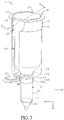
- FIG. 3 is a schematic diagram showing the assembled nucleic acid extraction component according to an embodiment of this invention.
- FIG. 4A is a sectional view of the nucleic acid extraction component of FIG. 3 along the line A-A.
- FIG. 4B is a sectional view of an inner tube according to another embodiment of this invention.
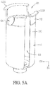
- FIGS. 5A and 5B are schematic diagrams showing the fixed tubes according to different embodiments of this invention.
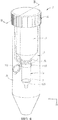
- FIG. 6 is a schematic diagram showing the assembled nucleic acid extraction component according to another embodiment of this invention.
- FIGS. 7 and 8 are an exploded view and an assembled view of a centrifugal component according to an embodiment of this invention.
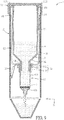
- FIG. 9 is a sectional view of the centrifugal component of FIG. 8 along the line B-B.
- the present invention extracts a very small amount of nucleic acid from a sample by a centrifuge machine with using a nucleic acid extraction component.
- the sample may be, for example but not limited to, blood, plasma, urine or tissue fluid.
- the nucleic acid extraction component of the invention can quickly and conveniently extract the larger volume of sample to obtain the high yield and high concentration nucleic acid without multiple extraction operations and enlarging the membrane column or membrane. The structure and features of the nucleic acid extraction component will be described in the following embodiments.
- FIGS. 1 to 4A Please refer to FIGS. 1 to 4A , wherein FIGS. 1 and 2 are exploded views of the nucleic acid extraction component according to an embodiment of this invention, FIG. 3 is a schematic diagram showing the assembled nucleic acid extraction component according to an embodiment of this invention, and FIG. 4A is a sectional view of the nucleic acid extraction component of FIG. 3 along the line A-A.
- the nucleic acid extraction component 1 comprises a fixed tube 11 and a membrane column 12.
- a membrane 3 is provided inside the membrane column 12.
- the nucleic acid extraction component 1 of this embodiment can further comprise an inner tube 13.
- the membrane column 12 is fitted in the fixed tube 11.
- the membrane column 12 is connected to the inner tube 13 and fitted in the fixed tube 11, and a part of the membrane column 12 is protruded beyond the fixed tube 11.
- the fixed tube 11, the membrane column 12 and the inner tube 13 are substantially cylindrical tubes, and the materials of the fixed tube 11, the membrane column 12 and the inner tube 13 are, for example but not limited to, plastic materials.
- the capacities and sizes of the fixed tube 11, the membrane column 12 and the inner tube 13 are not limited in this invention, and any configuration that the fixed tube 11, the membrane column 12 and the inner tube 13 can matched with each other is acceptable.
- the capacity of the membrane column 12 is between 0.5 ml and 1 ml, so that the membrane column 12 can only contain a few amount of sample.
- the membrane 3 configured inside the membrane column 12 is also very small.
- the capacity of the inner tube 13 is larger, which may contain the sample of more than 10 ml. Accordingly, when the sample solution contained in the membrane column 12 flows through the membrane 3, the sample contained in the inner tube 13 can be added to the membrane column 12. Since the inner tube 13 contains more sample volume, the membrane 3 can absorb more amount of nucleic acids after the centrifugal process, thereby extracting high concentration nucleic acid.
- the membrane column 12 and the inner tube 13 of this embodiment are two separated members, but this invention is not limited thereto.
- the membrane column 12 and the inner tube 13 can be integrally formed as a single structure, and this invention is not limited.
- the fixed tube 11 comprises a tube body 111, a tube opening portion 112, and a bottom portion 113.
- the tube body 111 extends along a first direction D1
- the bottom portion 113 and the tube opening portion 112 are respectively connected to two opposite sides of the tube body 111.
- One end of the tube opening portion 112 distal from the tube body 111 is provided with a protrusion 1121, which protrudes along a second direction D2.
- the first direction D1 is perpendicular to the second direction D2.
- the bottom portion 113 is provided with a shoulder 1131, a stepwise structure 1132, and a fourth opening 04.
- the diameter of the tube body 111 is greater than the diameter of the stepwise structure 1132, and the shoulder 1131 of the bottom portion 113 is connected to the membrane column 12.
- the stepwise structure 1132 extends from the fourth opening 04 along the first direction D1.
- the stepwise structure 1132 is connected with the membrane column 12, and the membrane column 12 protrudes beyond the fixed tube 11 through the stepwise structure 1132.
- the membrane column 12 protrudes beyond the fixed tube 11 through the fourth opening 04 of the bottom portion 113.
- each of two opposite sides of the tube opening portion 112 is configured with a first opening O1, and the first openings O1 divide the protrusion 1121 into two sections.
- an included angle is formed between the first direction D1 and the second direction D2.
- the included angle between the first direction D1 and the second direction D2 can be, for example but not limited to, 90 degrees.
- the included angle between the first direction D1 and the second direction D2 can be greater than 90 degrees (e.g. 120 degrees) or less than 90 degrees (e.g. 75 degrees), and this invention is not limited thereto.
- first openings O1 are formed at two opposite sides of the tube opening portion 112, respectively, so that the tube opening portion 112 and the protrusion 1121 can be divided into two sections.
- This configuration is benefit to the following operation.
- the diameter of the stepwise structure 1132 is gradually decreased in a direction departing from the tube body 111. That is, the part of the stepwise structure located farer away from the tube body 111 has a smaller diameter.
- One side of the tube body 111 is configured with a second opening 02, and the second opening 02 extends along the first direction D1 from one of the first openings O1 to the stepwise structure 1132.
- an additional second opening (not shown) can be formed at the other side of the tube body 111 opposite to the above-mentioned second opening 02.
- the additional second opening can also extend along the first direction D1 from the other one of the first openings O1.
- the fixed tube 11 is configured without the second opening 02 but is configured with a third opening 03.
- the third opening 03 extends along the first direction D1 from the protrusion 1121 of the tube opening portion 112 to the stepwise structure 1132.
- the fixed tube 11 can be configured without the first opening O1, the second opening 02, the third opening 03, and the stepwise structure 1132.
- the bottom portion 113 of the fixed tube 11 of this embodiment is configured with a shoulder 1131 and a fourth opening 04, but is configured without the stepwise structure 1132, the first opening O1, the second opening 02, and the third opening 03.
- the fixed tube 11 can be configured without the first opening O1, the second opening 02, and/or the third opening 03, but can be configured with the stepwise structure 1132.
- the fixed tube 11 can be configured without the stepwise structure 1132, but can be configured with the first opening O1, the second opening 02, and/or the third opening 03. This invention is not limited thereto.
- the membrane column 12 comprises a cylindrical tube portion 121, a first top portion 122 and a first bottom portion 125.
- the cylindrical tube portion 121 extends along a first direction D1, and the first top portion 122 and the first bottom portion 125 are connected with the opposite sides of the cylindrical tube portion 121, respectively.
- the first top portion 122 of the membrane column 12 has a ring shape
- the first bottom portion 125 has a funnel shape.
- the first bottom portion 125 and a part of the cylindrical tube portion 121 are protruded beyond the bottom portion 113 of the fixed tube 11.
- FIG. 3 the first bottom portion 125 and a part of the cylindrical tube portion 121 are protruded beyond the bottom portion 113 of the fixed tube 11.
- the bottom portion 113 of the fixed tube 11 is connected with the first top portion 122 of the membrane column 12, and the first bottom portion 125 of the membrane column 12 is protruded beyond the fixed tube 11 through the fourth opening 04 of the bottom portion 113.
- the membrane column 12 may not protrude beyond the fixed tube 11.
- the cylindrical tube portion 121 can be leveled with the bottom portion 113, or the cylindrical tube portion 121 can be sunk inside the bottom portion 113. This invention is not limited thereto.
- the diameter of the bottom portion 113 of the fixed tube 11 is configured corresponding to the diameter of the first top portion 122 of the membrane column 12, so that the shoulder 1131 of the fixed tube 11 can be fitted cover the outer periphery of the first top portion 122 of the membrane column 12.
- the extension portion 1221 of the first top portion 122 of the membrane column 12 is engaged with the shoulder 1131 of the fixed tube 11.
- the lower edge of the first top portion 122 of the membrane column 12 can be engaged with the stepwise structure 1132 of the bottom portion 113 of the fixed tube 11, thereby connecting the bottom portion 113 to the first top portion 122 of the membrane column 12.
- the diameter of the bottom portion 113 of the fixed tube 11 can be not configured corresponding to the diameter of the first top portion 122 of the membrane column 12, or they can be not tightly engaged.
- the lower edge of the first top portion 122 of the membrane column 12 can be engaged to the shoulder 1131 of the fixed tube 11 for connecting the membrane column 12 to the fixed tube 11, and this invention is not limited.
- the membrane column 12 of this embodiment further comprises a tube cap 123 and a connecting portion 124.
- the connecting portion 124 connects the tube cap 123 to the first top portion 122 of the membrane column 12.
- the tube cap 123 is configured to cover the first top portion 122 of the membrane column 12. Therefore, when the sample is placed inside the membrane column 12, the tube cap 123 can prevent the overflow of the sample (in practice, the tube cap 123 will be opened when extracting the nucleic acid).
- the tube body 111 is configured with a second opening 02
- the tube cap 123 can be moved downwardly from the first opening O1 to the shoulder 1131 through the second opening 02 of the tube body 111.
- the membrane column 12 can be disposed inside the fixe tube 11, and the first bottom portion 125 and a part of the cylindrical tube portion 121 of the membrane column 12 can be protruded beyond the fixed tube 11 through the fourth opening 04 of the bottom portion 113, thereby connecting the first top portion 122 of the membrane column 12 to the stepwise structure 1132.
- the membrane column 12 is configured without the tube cap 123 and the connecting portion 124, the second opening 02 of the tube body 111 is not needed.
- the inner tube 13 comprises a cylindrical tube portion 131, a second bottom portion 132 and a second top portion 133.
- the cylindrical tube portion 131 also extends along the first direction D1, and the second bottom portion 132 and the first top portion 133 are connected with the opposite sides of the cylindrical tube portion 131, respectively.
- the second top portion 133 has a ring shape
- the second bottom portion 132 has a funnel shape. The diameter thereof is corresponding to the diameter of the first top portion 122 of the membrane column 12, so that the second bottom portion 132 of the inner tube 13 can be inserted into the first top portion 122 of the membrane column 12 when connecting the inner tube 13 to the membrane column 12. Accordingly, the sample can flow from the inner tube 13 to the membrane column 12.
- the membrane column 12 when the membrane column 12 is connected to the inner tube 13 and is fitted inside the fixed tube 11, a part of the second bottom portion 132 of the inner tube 13 can be inserted into the membrane column 12 through the first top portion 122.
- the first top portion 122 of the membrane column 12 can be fitted over the outer periphery of the second bottom portion 132 of the inner tube 13, and then the inner tube 13 is disposed inside the fixed tube 11.
- the included angle ⁇ between the second bottom portion 132 and the cylindrical tube portion 131 can be greater than 157 degrees (as shown in FIG. 4A ) and be less than or equal to 180 degrees (as shown in FIG. 4B ).
- the inner tube 13 of this embodiment is not configured with the tube cap.
- the inner tube 13 can be configured with a tube cap (not shown) for covering the second top portion 133, and this invention is not limited.
- the membrane 3 is disposed inside the membrane column 12 and is located adjacent to the first bottom portion 125.
- the membrane 3 is, for example but not limited to, a silica membrane.
- the membrane 3 can carry positive charges, and the nucleic acids in the sample can carry negative charges after a pretreatment process. Accordingly, the nucleic acids can be attached to the membrane 3 due to the attraction of the positive and negative charges during the centrifugal process, and then the nucleic acids attached to the membrane 3 can be extracted in the following process.
- one end of the tube opening portion 112 distal from the tube body 111 is provided with a protrusion 1121 protruding along the second direction D2. This configuration allows the operator to easily retrieve the fixed tube 11.
- the design of the shoulder 1131 of the bottom portion 113 of the fixed tube 11 can be engaged with the membrane column 12, so that the sample will not be spilled from the membrane column 12 or the inner tube 13 during the centrifugal process, thereby increasing the success rate of the operation (if the membrane column 12 is not engaged, it may detach from the fixed tube 11 during the centrifugal process, so that the sample may be spilled from the membrane column 12 and will not pass through the membrane 3, resulting in the failure of the centrifugal process).
- the configuration of the first openings O1 of the fixed tube 11 can divide the protrusion 1121 into two sections, so that the extraction operation is easier.
- this design makes it easier to place the membrane column 12 and the inner tube 13 into the fixed tube 11, and to take the membrane column 12 and the inner tube 13 out of the fixed tube 11.
- the structural design of the nucleic acid extraction component 1 can quickly and conveniently extract larger yield and higher concentration of nucleic acid.
- FIGS. 7 to 9 wherein FIGS. 7 and 8 are an exploded view and an assembled view of a centrifugal component 2 according to an embodiment of this invention, and FIG. 9 is a sectional view of the centrifugal component 2 of FIG. 8 along the line B-B.
- the centrifugal component 2 comprises a nucleic acid extraction component 1, a centrifugal tube 21 and a tube cap 22.
- the specific technical features and modifications of the nucleic acid extraction component 1 can be referred to the above embodiments, so the detailed description thereof will be omitted.
- the capacity of the centrifugal tube 21 is, for example but not limited to, 50 ml.
- the membrane column 12 is connected to the inner tube 13 and then fitted in the fixed tube 11 so as to form the nucleic acid extraction component 1.
- the sample 4 is added into the inner tube 13 and the membrane column 12.
- the inner tube 13 has a larger capacity (e.g. more than 10 ml) for accommodating more sample 4.
- the nucleic acid extraction component 1 is placed into the centrifugal tube 21, so that the protrusion 1121 of the fixed tube 11 contacts against the tube opening 211 of the centrifugal tube 21, thereby installing the fixed tube 11 in the centrifugal tube 21.
- the entire centrifugal component 2 is disposed in the centrifuge machine. Then, the sample 4 can pass through the membrane 3 in the centrifugal process, and the nucleic acids in the sample 4 can be absorbed by the membrane 3, thereby extracting the nucleic acids from the sample 4.
- the inner tube 13 and the fixed tube 11 are not used.
- the capacity of the membrane column 12 is very small. Accordingly, it is needed to perform multiple operations for extracting a certain amount of nucleic acids, which will cause a lot of operation time and cost. If it is desired to obtain the required amount of nucleic acids in one operation, the size of the membrane column must be enlarged (e.g. more than 10 ml) for accommodating more sample, and a large-sized membrane is also needed for the enlarged membrane column.
- the above-mentioned method has the following three drawbacks.
- the concentration of the nucleic acid will be diluted, which may affect the following detection reaction (e.g. the NGS reaction).
- the pretreatment process for the sample is needed.
- the cleavage solution used in the pretreatment process contains a high concentration of salt, and even after washing with the washing solution, a small amount of salt still remains on the membrane.
- the membrane is too large, the amount of the remained salts is increased, and the remained salts will interfere the results of the following PCR (polymerization chain reaction).
- the multiple operation with the centrifugal component 2 is not needed, and the structure design of the fixed tube 11, the membrane column 12 and the inner tube 13 of the nucleic acid extraction component 1 can accommodate a larger amount of sample without enlarging the membrane column 12.
- the amount of nucleic acids in the liquid biopsy is very small and is far less than the maximum absorption amount of the membrane 3, so that the enlarged membrane 3 is not needed. Accordingly, the high yield of nucleic acids can be obtained by one operation. Therefore, this invention does not have the above three drawbacks, and can elute the membrane to obtain the nucleic acids with a fewer amount of solution. Compared with the conventional art, this invention only needs one extraction operation to obtain the higher yield and higher concentration nucleic acids.
- the membrane column 12 is supported by the fixed tube 11.
- the membrane column 12 can be took out of the fixed tube 11 and then placed in a collection tube (e.g. 2 ml), followed by the steps of washing, drying and elution. Accordingly, the membrane column 12 and the fixed tube 11 of this invention can be separated, and this design makes the following three steps much easier.
- the sample 4 can be eluted in, for example, a 1.5 ml centrifugal tube by utilizing a smaller volume of solution, thereby increasing the concentration of the nucleic acids.
- the membrane column 12 can be easily stored for the operation next time.
- one end of the tube opening portion of the fixed tube distal from the tube body is provided with a protrusion.
- This configuration allows the operator to easily retrieve the fixed tube from the centrifugal tube.
- the membrane column does not separate from the inner tube during the centrifugal operation, so that the sample will not be spilled from the membrane column, thereby increasing the success rate of the operation.
- the design of the fixed tube and the membrane column of the nucleic acid extraction component of this invention can quickly and conveniently extract high yield and high concentration nucleic acids from a large volume of sample.
- the design of the first openings of the fixed tube can divide the protrusion into two sections, so that the operation of the extraction procedure can be easier.
Abstract
Description
- This application claims the benefit of
CN Patent Application No. 201710519911.9 - The invention relates to a fixed tube and, in particular, to a fixed tube of a nucleic acid extraction component and a nucleic acid extraction component.
- With the advancement of human genome sequencing technology, the advance in biomedical analysis technology, and the development of big data analysis tools, the era of precision medicine has arrived. The precision medicine is a customized medical model based on human genome information, combined with related internal environmental information such as proteome and metabolome, to design optimal treatment plans for patients to maximize therapeutic effects and minimize side effects.
- Blood is a red opaque viscous liquid that flows through the blood vessels and heart of the human body. The main contents of blood include plasma, blood cells, and genetic material (chromosomes and genes). Among them, cfDNA (cell free DNA) are degraded DNA fragments found in plasma that are freely circulating in the blood stream, and ctDNA are circulating tumor DNA, which refers to DNA fragments in cfDNA released from a tumor.
- Almost everyone's blood contains free DNA fragments (cfDNA), which may be derived from cell apoptosis or necrosis, or may enter the blood by active release (severe exercise). However, the amount of cfDNA in the blood is very low. In 1 ml of plasma, the amount of cfDNA is between about 1 ng and 100 ng, and the amount of ctDNA is much lower, which is only 0.1%~5% of cfDNA.
- Some studies have indicated that the total amount of cfDNA in peripheral blood of patients with tumors is higher than that of healthy people. Based on these studies, if the amount of cfDNA is increased, it can be a good indication as a means for screening tumors. Therefore, the purification of a liquid biopsy to obtain a very small amount of cfDNA (a type of nucleic acid) is the first step in precision medicine.
- In the manual purification procedure for liquid biopsy to obtain cell free nucleic acid, a very small amount of nucleic acid, is generally extracted from the sample through a silica gel membrane in a column system. In order to obtain more nucleic acids, the conventional art is to use a small volume (e.g. 0.7 ml) of membrane column and to operate the purification procedure for multiple times, or to increase the size of the membrane column so as to obtain more nucleic acids in one operation with the larger volume (e.g. more than 10 ml) of membrane column and the corresponding larger silica gel membrane. However, the first method will consume a considerable amount of operating time and cost. The second method can obtain a larger amount of nucleic acids in one operation, but the silica gel membrane of the large membrane column is enlarged and thickened, so that more solution is required for eluting the nucleic acids from the silica gel membrane. Thus, the concentration of the obtained cell free nucleic acids will be reduced.
- An objective of this invention is to provide a fixed tube of a nucleic acid extraction component and a nucleic acid extraction component. Compared with the above-mentioned conventional art, the design of the nucleic acid extraction component of this invention can quickly and conveniently extract high concentration nucleic acids from a large volume of sample.
- The present invention discloses a fixed tube of a nucleic acid extraction component. The nucleic acid extraction component comprises a membrane column fitted in the fixed tube. The fixed tube comprises a tube body, a tube opening portion, and a bottom portion. The tube body extends along a first direction. One end of the tube opening portion distal from the tube body is provided with a protrusion, which protrudes along a second direction, and the first direction is perpendicular to the second direction. The bottom portion and the tube opening portion are respectively connected to two opposite sides of the tube body. The bottom portion is provided with a shoulder, and the shoulder of the bottom portion is connected to the membrane column.
- In one embodiment, each of two opposite sides of the tube opening portion is configured with a first opening, and the first openings divide the protrusion into two sections.
- In one embodiment, the bottom portion further comprises a stepwise structure and a fourth opening, the stepwise structure extends from the fourth opening along the first direction, the stepwise structure is connected with the membrane column, and the membrane column protrudes beyond the fixed tube through the stepwise structure.
- In one embodiment, a diameter of the tube body is greater than a diameter of the stepwise structure.
- In one embodiment, a diameter of the stepwise structure is gradually decreased in a direction departing from the tube body.
- In one embodiment, the tube body is configured with a second opening, and the second opening extends along the first direction from one of the first openings to the stepwise structure.
- In one embodiment, the fixed tube comprises a third opening, and the third opening extends along the first direction from the tube opening portion to the stepwise structure.
- In one embodiment, the membrane column comprises a first top portion, and the shoulder of the fixed tube is fitted over an outer periphery of the first top portion of the membrane column.
- The present invention also discloses a nucleic acid extraction component, which comprises a membrane column and the above-mentioned fixed tube.
- In one embodiment, the protrusion of the fixed tube contacts against an opening of a centrifugal tube.
- As mentioned above, in the fixed tube of a nucleic acid extraction component and the nucleic acid extraction component of this invention, one end of the tube opening portion of the fixed tube distal from the tube body is provided with a protrusion. This configuration allows the operator to easily retrieve the fixed tube from the centrifugal tube. In addition, due to the design of the bottom portion of the fixed tube, the membrane column does not fall in the bottom of the centrifugal tube during the centrifugal operation, so that the sample will not be spilled from the membrane column, thereby increasing the success rate of the operation. In addition, the design of the fixed tube and the membrane column of the nucleic acid extraction component of this invention can quickly and conveniently extract high concentration nucleic acids from a large volume of sample.
- In one embodiment of this invention, the design of the first openings of the fixed tube can divide the protrusion into two sections, so that the operation of the extraction procedure can be easier.
- The invention will become more fully understood from the detailed description and accompanying drawings.
-
FIGS. 1 and2 are exploded views of the nucleic acid extraction component according to an embodiment of this invention. -
FIG. 3 is a schematic diagram showing the assembled nucleic acid extraction component according to an embodiment of this invention. -
FIG. 4A is a sectional view of the nucleic acid extraction component ofFIG. 3 along the line A-A. -
FIG. 4B is a sectional view of an inner tube according to another embodiment of this invention. -
FIGS. 5A and5B are schematic diagrams showing the fixed tubes according to different embodiments of this invention. -
FIG. 6 is a schematic diagram showing the assembled nucleic acid extraction component according to another embodiment of this invention. -
FIGS. 7 and8 are an exploded view and an assembled view of a centrifugal component according to an embodiment of this invention. -
FIG. 9 is a sectional view of the centrifugal component ofFIG. 8 along the line B-B. - The fixed tube of a nucleic acid extraction component and the nucleic acid extraction component of this invention will be apparent from the following embodiments with reference to the accompanying drawings, wherein the same references relate to the same elements.
- In the nucleic acid purification process of liquid biopsy, the present invention extracts a very small amount of nucleic acid from a sample by a centrifuge machine with using a nucleic acid extraction component. The sample may be, for example but not limited to, blood, plasma, urine or tissue fluid. In addition, the nucleic acid extraction component of the invention can quickly and conveniently extract the larger volume of sample to obtain the high yield and high concentration nucleic acid without multiple extraction operations and enlarging the membrane column or membrane. The structure and features of the nucleic acid extraction component will be described in the following embodiments.
- Please refer to
FIGS. 1 to 4A , whereinFIGS. 1 and2 are exploded views of the nucleic acid extraction component according to an embodiment of this invention,FIG. 3 is a schematic diagram showing the assembled nucleic acid extraction component according to an embodiment of this invention, andFIG. 4A is a sectional view of the nucleic acid extraction component ofFIG. 3 along the line A-A. - As shown in
FIGS. 1 to 4A , the nucleicacid extraction component 1 comprises a fixedtube 11 and amembrane column 12. In this embodiment, amembrane 3 is provided inside themembrane column 12. In addition, the nucleicacid extraction component 1 of this embodiment can further comprise aninner tube 13. - The
membrane column 12 is fitted in the fixedtube 11. In this embodiment, themembrane column 12 is connected to theinner tube 13 and fitted in the fixedtube 11, and a part of themembrane column 12 is protruded beyond the fixedtube 11. Herein, the fixedtube 11, themembrane column 12 and theinner tube 13 are substantially cylindrical tubes, and the materials of the fixedtube 11, themembrane column 12 and theinner tube 13 are, for example but not limited to, plastic materials. In addition, the capacities and sizes of the fixedtube 11, themembrane column 12 and theinner tube 13 are not limited in this invention, and any configuration that the fixedtube 11, themembrane column 12 and theinner tube 13 can matched with each other is acceptable. In some embodiments, for example, the capacity of themembrane column 12 is between 0.5 ml and 1 ml, so that themembrane column 12 can only contain a few amount of sample. Of course, themembrane 3 configured inside themembrane column 12 is also very small. In some embodiments, the capacity of theinner tube 13 is larger, which may contain the sample of more than 10 ml. Accordingly, when the sample solution contained in themembrane column 12 flows through themembrane 3, the sample contained in theinner tube 13 can be added to themembrane column 12. Since theinner tube 13 contains more sample volume, themembrane 3 can absorb more amount of nucleic acids after the centrifugal process, thereby extracting high concentration nucleic acid. Moreover, themembrane column 12 and theinner tube 13 of this embodiment are two separated members, but this invention is not limited thereto. In some embodiments, themembrane column 12 and theinner tube 13 can be integrally formed as a single structure, and this invention is not limited. - The fixed
tube 11 comprises atube body 111, atube opening portion 112, and abottom portion 113. Thetube body 111 extends along a first direction D1, and thebottom portion 113 and thetube opening portion 112 are respectively connected to two opposite sides of thetube body 111. One end of thetube opening portion 112 distal from thetube body 111 is provided with aprotrusion 1121, which protrudes along a second direction D2. The first direction D1 is perpendicular to the second direction D2. Moreover, in this embodiment, thebottom portion 113 is provided with ashoulder 1131, astepwise structure 1132, and afourth opening 04. In this case, the diameter of thetube body 111 is greater than the diameter of thestepwise structure 1132, and theshoulder 1131 of thebottom portion 113 is connected to themembrane column 12. Thestepwise structure 1132 extends from thefourth opening 04 along the first direction D1. Thestepwise structure 1132 is connected with themembrane column 12, and themembrane column 12 protrudes beyond the fixedtube 11 through thestepwise structure 1132. In this embodiment, themembrane column 12 protrudes beyond the fixedtube 11 through thefourth opening 04 of thebottom portion 113. - In this embodiment, each of two opposite sides of the
tube opening portion 112 is configured with a first opening O1, and the first openings O1 divide theprotrusion 1121 into two sections. Herein, an included angle is formed between the first direction D1 and the second direction D2. In this embodiment, the included angle between the first direction D1 and the second direction D2 can be, for example but not limited to, 90 degrees. In different embodiments, the included angle between the first direction D1 and the second direction D2 can be greater than 90 degrees (e.g. 120 degrees) or less than 90 degrees (e.g. 75 degrees), and this invention is not limited thereto. Specifically, two first openings O1 are formed at two opposite sides of thetube opening portion 112, respectively, so that thetube opening portion 112 and theprotrusion 1121 can be divided into two sections. This configuration is benefit to the following operation. In addition, the diameter of thestepwise structure 1132 is gradually decreased in a direction departing from thetube body 111. That is, the part of the stepwise structure located farer away from thetube body 111 has a smaller diameter. Thus, when themembrane column 12 is connected with theinner tube 13 and fitted inside the fixedtube 11, themembrane column 12 and theinner tube 13 can be fixed, so that themembrane column 12 will not be separated from theinner tube 13. - One side of the
tube body 111 is configured with asecond opening 02, and thesecond opening 02 extends along the first direction D1 from one of the first openings O1 to thestepwise structure 1132. In different embodiments, an additional second opening (not shown) can be formed at the other side of thetube body 111 opposite to the above-mentionedsecond opening 02. The additional second opening can also extend along the first direction D1 from the other one of the first openings O1. Alternatively, as shown inFIG. 5A , except the first openings O1, the fixedtube 11 is configured without thesecond opening 02 but is configured with athird opening 03. Thethird opening 03 extends along the first direction D1 from theprotrusion 1121 of thetube opening portion 112 to thestepwise structure 1132. In some embodiments, the fixedtube 11 can be configured without the first opening O1, thesecond opening 02, thethird opening 03, and thestepwise structure 1132. As shown inFIG. 5B , thebottom portion 113 of the fixedtube 11 of this embodiment is configured with ashoulder 1131 and afourth opening 04, but is configured without thestepwise structure 1132, the first opening O1, thesecond opening 02, and thethird opening 03. Alternatively, in other embodiments, the fixedtube 11 can be configured without the first opening O1, thesecond opening 02, and/or thethird opening 03, but can be configured with thestepwise structure 1132. In other embodiments, the fixedtube 11 can be configured without thestepwise structure 1132, but can be configured with the first opening O1, thesecond opening 02, and/or thethird opening 03. This invention is not limited thereto. - The
membrane column 12 comprises acylindrical tube portion 121, a firsttop portion 122 and afirst bottom portion 125. Thecylindrical tube portion 121 extends along a first direction D1, and the firsttop portion 122 and thefirst bottom portion 125 are connected with the opposite sides of thecylindrical tube portion 121, respectively. In this embodiment, the firsttop portion 122 of themembrane column 12 has a ring shape, and thefirst bottom portion 125 has a funnel shape. As shown inFIG. 3 , thefirst bottom portion 125 and a part of thecylindrical tube portion 121 are protruded beyond thebottom portion 113 of the fixedtube 11. In addition, as shown inFIG. 4A , thebottom portion 113 of the fixedtube 11 is connected with the firsttop portion 122 of themembrane column 12, and thefirst bottom portion 125 of themembrane column 12 is protruded beyond the fixedtube 11 through thefourth opening 04 of thebottom portion 113. Of course, in different embodiments, themembrane column 12 may not protrude beyond the fixedtube 11. For example, thecylindrical tube portion 121 can be leveled with thebottom portion 113, or thecylindrical tube portion 121 can be sunk inside thebottom portion 113. This invention is not limited thereto. - Specifically, in order to fix the
membrane column 12 by the fixedtube 11, the diameter of thebottom portion 113 of the fixedtube 11 is configured corresponding to the diameter of the firsttop portion 122 of themembrane column 12, so that theshoulder 1131 of the fixedtube 11 can be fitted cover the outer periphery of the firsttop portion 122 of themembrane column 12. As shown inFIG. 4A , theextension portion 1221 of the firsttop portion 122 of themembrane column 12 is engaged with theshoulder 1131 of the fixedtube 11. Thus, the lower edge of the firsttop portion 122 of themembrane column 12 can be engaged with thestepwise structure 1132 of thebottom portion 113 of the fixedtube 11, thereby connecting thebottom portion 113 to the firsttop portion 122 of themembrane column 12. To be noted, in some embodiments, the diameter of thebottom portion 113 of the fixedtube 11 can be not configured corresponding to the diameter of the firsttop portion 122 of themembrane column 12, or they can be not tightly engaged. For example, the lower edge of the firsttop portion 122 of themembrane column 12 can be engaged to theshoulder 1131 of the fixedtube 11 for connecting themembrane column 12 to the fixedtube 11, and this invention is not limited. In addition, themembrane column 12 of this embodiment further comprises atube cap 123 and a connectingportion 124. The connectingportion 124 connects thetube cap 123 to the firsttop portion 122 of themembrane column 12. In this embodiment, thetube cap 123 is configured to cover the firsttop portion 122 of themembrane column 12. Therefore, when the sample is placed inside themembrane column 12, thetube cap 123 can prevent the overflow of the sample (in practice, thetube cap 123 will be opened when extracting the nucleic acid). - In addition, with reference to
FIG. 3 , in this embodiment, since thetube body 111 is configured with asecond opening 02, when themembrane column 12 is disposed in the fixedtube 11, thetube cap 123 can be moved downwardly from the first opening O1 to theshoulder 1131 through thesecond opening 02 of thetube body 111. Accordingly, themembrane column 12 can be disposed inside thefixe tube 11, and thefirst bottom portion 125 and a part of thecylindrical tube portion 121 of themembrane column 12 can be protruded beyond the fixedtube 11 through thefourth opening 04 of thebottom portion 113, thereby connecting the firsttop portion 122 of themembrane column 12 to thestepwise structure 1132. In other embodiments, as shown inFIG. 6 , if themembrane column 12 is configured without thetube cap 123 and the connectingportion 124, thesecond opening 02 of thetube body 111 is not needed. - In this embodiment, the
inner tube 13 comprises acylindrical tube portion 131, asecond bottom portion 132 and a secondtop portion 133. Thecylindrical tube portion 131 also extends along the first direction D1, and thesecond bottom portion 132 and the firsttop portion 133 are connected with the opposite sides of thecylindrical tube portion 131, respectively. In this embodiment, the secondtop portion 133 has a ring shape, and thesecond bottom portion 132 has a funnel shape. The diameter thereof is corresponding to the diameter of the firsttop portion 122 of themembrane column 12, so that thesecond bottom portion 132 of theinner tube 13 can be inserted into the firsttop portion 122 of themembrane column 12 when connecting theinner tube 13 to themembrane column 12. Accordingly, the sample can flow from theinner tube 13 to themembrane column 12. Moreover, in this embodiment, when themembrane column 12 is connected to theinner tube 13 and is fitted inside the fixedtube 11, a part of thesecond bottom portion 132 of theinner tube 13 can be inserted into themembrane column 12 through the firsttop portion 122. Thus, the firsttop portion 122 of themembrane column 12 can be fitted over the outer periphery of thesecond bottom portion 132 of theinner tube 13, and then theinner tube 13 is disposed inside the fixedtube 11. As shown inFIGS. 4A and4B , the included angle α between thesecond bottom portion 132 and thecylindrical tube portion 131 can be greater than 157 degrees (as shown inFIG. 4A ) and be less than or equal to 180 degrees (as shown inFIG. 4B ). This configuration can prevent the residual sample around the included angle α, thereby further improving the extraction efficiency of the nucleicacid extraction component 1. In addition, theinner tube 13 of this embodiment is not configured with the tube cap. However, in other embodiments, theinner tube 13 can be configured with a tube cap (not shown) for covering the secondtop portion 133, and this invention is not limited. - The
membrane 3 is disposed inside themembrane column 12 and is located adjacent to thefirst bottom portion 125. In some embodiments, themembrane 3 is, for example but not limited to, a silica membrane. Themembrane 3 can carry positive charges, and the nucleic acids in the sample can carry negative charges after a pretreatment process. Accordingly, the nucleic acids can be attached to themembrane 3 due to the attraction of the positive and negative charges during the centrifugal process, and then the nucleic acids attached to themembrane 3 can be extracted in the following process. - As mentioned above, in the nucleic
acid extraction component 1 of this embodiment, one end of thetube opening portion 112 distal from thetube body 111 is provided with aprotrusion 1121 protruding along the second direction D2. This configuration allows the operator to easily retrieve the fixedtube 11. In addition, the design of theshoulder 1131 of thebottom portion 113 of the fixedtube 11 can be engaged with themembrane column 12, so that the sample will not be spilled from themembrane column 12 or theinner tube 13 during the centrifugal process, thereby increasing the success rate of the operation (if themembrane column 12 is not engaged, it may detach from the fixedtube 11 during the centrifugal process, so that the sample may be spilled from themembrane column 12 and will not pass through themembrane 3, resulting in the failure of the centrifugal process). In addition, the configuration of the first openings O1 of the fixedtube 11 can divide theprotrusion 1121 into two sections, so that the extraction operation is easier. For example, this design makes it easier to place themembrane column 12 and theinner tube 13 into the fixedtube 11, and to take themembrane column 12 and theinner tube 13 out of the fixedtube 11. In addition, since theinner tube 13 has a larger capacity for accommodating more sample but the size of themembrane 3 is remained, the structural design of the nucleicacid extraction component 1 can quickly and conveniently extract larger yield and higher concentration of nucleic acid. - Please refer to
FIGS. 7 to 9 , whereinFIGS. 7 and8 are an exploded view and an assembled view of acentrifugal component 2 according to an embodiment of this invention, andFIG. 9 is a sectional view of thecentrifugal component 2 ofFIG. 8 along the line B-B. - In this embodiment, the
centrifugal component 2 comprises a nucleicacid extraction component 1, acentrifugal tube 21 and atube cap 22. The specific technical features and modifications of the nucleicacid extraction component 1 can be referred to the above embodiments, so the detailed description thereof will be omitted. - In some embodiments, the capacity of the
centrifugal tube 21 is, for example but not limited to, 50 ml. In practice, themembrane column 12 is connected to theinner tube 13 and then fitted in the fixedtube 11 so as to form the nucleicacid extraction component 1. Afterwards, thesample 4 is added into theinner tube 13 and themembrane column 12. In this case, theinner tube 13 has a larger capacity (e.g. more than 10 ml) for accommodatingmore sample 4. Next, the nucleicacid extraction component 1 is placed into thecentrifugal tube 21, so that theprotrusion 1121 of the fixedtube 11 contacts against thetube opening 211 of thecentrifugal tube 21, thereby installing the fixedtube 11 in thecentrifugal tube 21. After closing thetube cap 22 to cover the centrifugal tube 21 (by, for example but not limited to, locking), the entirecentrifugal component 2 is disposed in the centrifuge machine. Then, thesample 4 can pass through themembrane 3 in the centrifugal process, and the nucleic acids in thesample 4 can be absorbed by themembrane 3, thereby extracting the nucleic acids from thesample 4. - In the conventional art of extracting the nucleic acids, the
inner tube 13 and the fixedtube 11 are not used. In addition, the capacity of themembrane column 12 is very small. Accordingly, it is needed to perform multiple operations for extracting a certain amount of nucleic acids, which will cause a lot of operation time and cost. If it is desired to obtain the required amount of nucleic acids in one operation, the size of the membrane column must be enlarged (e.g. more than 10 ml) for accommodating more sample, and a large-sized membrane is also needed for the enlarged membrane column. - However, the above-mentioned method has the following three drawbacks. (1) When a large-sized membrane is used to obtain the same amount of nucleic acids, the nucleic acids will be distributed on and attached to the large-sized membrane, but the solution (e.g. pure water) for eluting the membrane may not cover the entire membrane, which can cause the low recovery rate of the nucleic acids. (2) If more solution is provided to eluting the membrane, the concentration of the nucleic acid will be diluted, which may affect the following detection reaction (e.g. the NGS reaction). (3) In order to make the nucleic acids to carry negative charges, the pretreatment process for the sample is needed. However, the cleavage solution used in the pretreatment process contains a high concentration of salt, and even after washing with the washing solution, a small amount of salt still remains on the membrane. When the membrane is too large, the amount of the remained salts is increased, and the remained salts will interfere the results of the following PCR (polymerization chain reaction).
- In this embodiment, the multiple operation with the
centrifugal component 2 is not needed, and the structure design of the fixedtube 11, themembrane column 12 and theinner tube 13 of the nucleicacid extraction component 1 can accommodate a larger amount of sample without enlarging themembrane column 12. In addition, the amount of nucleic acids in the liquid biopsy is very small and is far less than the maximum absorption amount of themembrane 3, so that theenlarged membrane 3 is not needed. Accordingly, the high yield of nucleic acids can be obtained by one operation. Therefore, this invention does not have the above three drawbacks, and can elute the membrane to obtain the nucleic acids with a fewer amount of solution. Compared with the conventional art, this invention only needs one extraction operation to obtain the higher yield and higher concentration nucleic acids. - To be noted, in the above embodiment, the
membrane column 12 is supported by the fixedtube 11. In order to perform the following elution process for obtaining the nucleic acids easier, themembrane column 12 can be took out of the fixedtube 11 and then placed in a collection tube (e.g. 2 ml), followed by the steps of washing, drying and elution. Accordingly, themembrane column 12 and the fixedtube 11 of this invention can be separated, and this design makes the following three steps much easier. In addition, thesample 4 can be eluted in, for example, a 1.5 ml centrifugal tube by utilizing a smaller volume of solution, thereby increasing the concentration of the nucleic acids. Moreover, themembrane column 12 can be easily stored for the operation next time. - As mentioned above, in the fixed tube of a nucleic acid extraction component and the nucleic acid extraction component of this invention, one end of the tube opening portion of the fixed tube distal from the tube body is provided with a protrusion. This configuration allows the operator to easily retrieve the fixed tube from the centrifugal tube. In addition, due to the design of the bottom portion of the fixed tube, the membrane column does not separate from the inner tube during the centrifugal operation, so that the sample will not be spilled from the membrane column, thereby increasing the success rate of the operation. In addition, the design of the fixed tube and the membrane column of the nucleic acid extraction component of this invention can quickly and conveniently extract high yield and high concentration nucleic acids from a large volume of sample.
- In one embodiment of this invention, the design of the first openings of the fixed tube can divide the protrusion into two sections, so that the operation of the extraction procedure can be easier.
- Although the invention has been described with reference to specific embodiments, this description is not meant to be construed in a limiting sense. Various modifications of the disclosed embodiments, as well as alternative embodiments, will be apparent to persons skilled in the art. It is, therefore, contemplated that the appended claims will cover all modifications that fall within the true scope of the invention.
Claims (10)
- A fixed tube of a nucleic acid extraction component, wherein the nucleic acid extraction component comprises a membrane column fitted in the fixed tube, which is characterized in that the fixed tube comprises:a tube body extending along a first direction;a tube opening portion, wherein one end of the tube opening portion distal from
the tube body is provided with a protrusion, which protrudes along a second direction, and the first direction is perpendicular to the second direction; anda bottom portion, wherein the bottom portion and the tube opening portion are
respectively connected to two opposite sides of the tube body, the bottom portion is provided with a shoulder, and the shoulder of the bottom portion is connected to the membrane column. - The fixed tube of claim 1, which is characterized in that each of two opposite sides of the tube opening portion is configured with a first opening, and the first openings divide the protrusion into two sections.
- The fixed tube of claim 2, which is characterized in that the bottom portion further comprises a stepwise structure and a fourth opening, the stepwise structure extends from the fourth opening along the first direction, the stepwise structure is connected with the membrane column, and the membrane column protrudes beyond the fixed tube through the stepwise structure.
- The fixed tube of claim 3, which is characterized in that a diameter of the tube body is greater than a diameter of the stepwise structure.
- The fixed tube of claim 3, which is characterized in that a diameter of the stepwise structure is gradually decreased in a direction departing from the tube body.
- The fixed tube of claim 3, which is characterized in that the tube body is configured with a second opening, and the second opening extends along the first direction from one of the first openings to the stepwise structure.
- The fixed tube of claim 3, which is characterized in that the fixed tube comprises a third opening, and the third opening extends along the first direction from the tube opening portion to the stepwise structure.
- The fixed tube of claim 1, which is characterized in that the membrane column comprises a first top portion, and the shoulder of the fixed tube is fitted over an outer periphery of the first top portion of the membrane column.
- A nucleic acid extraction component, which is characterized in that the nucleic acid extraction component comprises:a membrane column; anda fixed tube of any of claims 1 to 8.
- The nucleic acid extraction component of claim 9, which is characterized in that the protrusion of the fixed tube contacts against an opening of a centrifugal tube.
Applications Claiming Priority (2)
| Application Number | Priority Date | Filing Date | Title |
|---|---|---|---|
| CN201710519911.9A CN109207340B (en) | 2017-06-30 | 2017-06-30 | Nucleic acid extraction assembly |
| PCT/CN2018/089930 WO2019001228A1 (en) | 2017-06-30 | 2018-06-05 | Fixed tube of nucleic acid extraction component, and nucleic acid extraction component |
Publications (2)
| Publication Number | Publication Date |
|---|---|
| EP3647408A1 true EP3647408A1 (en) | 2020-05-06 |
| EP3647408A4 EP3647408A4 (en) | 2021-03-24 |
Family
ID=64741090
Family Applications (1)
| Application Number | Title | Priority Date | Filing Date |
|---|---|---|---|
| EP18822770.6A Pending EP3647408A4 (en) | 2017-06-30 | 2018-06-05 | Fixed tube of nucleic acid extraction component, and nucleic acid extraction component |
Country Status (4)
| Country | Link |
|---|---|
| US (1) | US11365406B2 (en) |
| EP (1) | EP3647408A4 (en) |
| CN (1) | CN109207340B (en) |
| WO (1) | WO2019001228A1 (en) |
Families Citing this family (4)
| Publication number | Priority date | Publication date | Assignee | Title |
|---|---|---|---|---|
| EP3924712A4 (en) * | 2019-02-13 | 2022-11-23 | The Trustees of Columbia University in the City of New York | Medical apparatus and method for collection and preparation of biological samples |
| KR102500163B1 (en) * | 2020-07-14 | 2023-02-15 | 주식회사 미루시스템즈 | Pipet for separation of nucleic acid and method of separating nucleic acid by using the same |
| KR102427536B1 (en) * | 2020-07-14 | 2022-08-02 | 주식회사 미루시스템즈 | Pipet for separation of nucleic acid and method of separating nucleic acid by using the same |
| CN113234576B (en) * | 2021-05-07 | 2022-07-29 | 青岛大学附属医院 | Improved novel coronavirus storage test tube |
Family Cites Families (31)
| Publication number | Priority date | Publication date | Assignee | Title |
|---|---|---|---|---|
| DE3843610A1 (en) * | 1988-01-13 | 1989-07-27 | Stephan Dr Diekmann | DISCONNECTING OR REACTION PILLAR UNIT |
| CN1299413A (en) | 1998-04-02 | 2001-06-13 | 李璟日 | Glass microfiber column and method for the prepn. and purification of plasmid DNA using the same |
| CN2394917Y (en) * | 1999-02-03 | 2000-09-06 | 王欣波 | Rotary centrifugal column for nucleic acid |
| DE20111082U1 (en) * | 2001-07-06 | 2001-10-31 | Macherey Nagel Gmbh & Co Hg | Device for the treatment of biomolecules |
| US20030091989A1 (en) | 2001-08-20 | 2003-05-15 | Whatman, Inc. | DNA purification and recovery from high particulate and solids samples |
| US20030098271A1 (en) * | 2001-11-26 | 2003-05-29 | Ralph Somack | Capsule and tray systems for combined sample collection, archiving, purification, and PCR |
| US20070148649A1 (en) | 2003-10-21 | 2007-06-28 | Fuji Photo Film Co., Ltd. | Cartridge for nucleic acid separation and purification and method for producing the same |
| US7897378B2 (en) * | 2004-03-18 | 2011-03-01 | Roche Molecular Systems, Inc. | Method and device for purifying nucleic acids |
| EP1807207B1 (en) * | 2004-09-30 | 2013-10-23 | Kurashiki Boseki Kabushiki Kaisha | Multiple cartridge and cartridge array frame |
| CN2793074Y (en) * | 2005-02-07 | 2006-07-05 | 宁波唯奥基因科技发展有限公司 | DNA extractor |
| KR101006562B1 (en) * | 2008-06-27 | 2011-01-07 | 포항공과대학교 산학협력단 | Nucleic acid extraction method |
| WO2010065018A1 (en) * | 2008-12-04 | 2010-06-10 | Thermogenesis Corp. | Apparatus and method for separating and isolating components of a biological fluid |
| CN201527375U (en) * | 2009-06-16 | 2010-07-14 | 上海捷瑞生物工程有限公司 | Nucleic acid separating and purifying column |
| EP2675494B1 (en) * | 2011-02-17 | 2016-05-18 | Nestec S.A. | Apparatus and method for isolating leukocytes and tumor cells by filtration |
| US9304070B2 (en) * | 2011-07-13 | 2016-04-05 | Emd Millipore Corporation | All-in-one sample preparation device and method |
| US20140018529A1 (en) * | 2012-07-12 | 2014-01-16 | E I Du Pont De Nemours And Company | Nucleic acid isolation and purification system |
| CN105122031B (en) * | 2012-11-20 | 2019-02-01 | 纽约哥伦比亚大学董事会 | Medical Devices and method for collecting biological sample |
| CN103571914B (en) * | 2013-02-25 | 2015-11-25 | 哈尔滨医科大学 | Obtain acquisition method and the device of nucleic acid clinical samples |
| CN104043491B (en) * | 2013-03-13 | 2016-08-10 | 精浚科技股份有限公司 | Suction pipe fitting |
| CN204058439U (en) | 2013-07-12 | 2014-12-31 | 中国人民解放军疾病预防控制所 | A kind of instrument cases for nucleic acid rapid extraction |
| CN104059849B (en) * | 2013-07-12 | 2017-01-18 | 中国人民解放军疾病预防控制所 | Device and method used for rapid extraction of nucleic acid |
| CN105980846B (en) * | 2014-02-21 | 2018-12-07 | 宝生物工程美国有限公司 | The method of column spinner and its manufacture and use including poly- (acid) UF membrane matrix |
| CN203846026U (en) * | 2014-05-20 | 2014-09-24 | 厦门艾德生物医药科技有限公司 | Device for collecting circulating tumor cell |
| CN204022828U (en) | 2014-07-24 | 2014-12-17 | 精专生医股份有限公司 | The device of extracting nucleic acid molecule |
| CN105441318B (en) | 2014-08-15 | 2018-02-13 | 冠研(上海)专利技术有限公司 | It is configured with the nucleic acid product extraction equipment of barriers |
| CN105062888B (en) * | 2015-09-02 | 2017-09-15 | 苏州东胜兴业科学仪器有限公司 | Bar magnet pipe sleeve, multi-joint component and instrument for extracting nucleic acid |
| CN205182760U (en) * | 2015-10-16 | 2016-04-27 | 南京汉隆实验器材有限公司 | Can invert eccentric centrifuging tube |
| CN205774465U (en) * | 2016-05-27 | 2016-12-07 | 疏义林 | A kind of vacuum nucleic acid extraction column for extracting cfDNA |
| CN206069861U (en) * | 2016-07-11 | 2017-04-05 | 四川农业大学 | A kind of centrifuge tube for separating plant intercellular washing fluids |
| CN106546674A (en) * | 2016-10-20 | 2017-03-29 | 北京蛋白质组研究中心 | With the method and its special purpose device of a small amount of sample fast enriching, separation, identification and quantitative endogenous transcription factor and its compound |
| TWM551624U (en) | 2017-06-30 | 2017-11-11 | 開啟基因股份有限公司 | Fixed tube of nucleic acid extraction assembly and nucleic acid extraction assembly |
-
2017
- 2017-06-30 CN CN201710519911.9A patent/CN109207340B/en active Active
-
2018
- 2018-06-05 EP EP18822770.6A patent/EP3647408A4/en active Pending
- 2018-06-05 WO PCT/CN2018/089930 patent/WO2019001228A1/en active Application Filing
- 2018-06-05 US US16/626,834 patent/US11365406B2/en active Active
Also Published As
| Publication number | Publication date |
|---|---|
| CN109207340A (en) | 2019-01-15 |
| US20200131503A1 (en) | 2020-04-30 |
| WO2019001228A1 (en) | 2019-01-03 |
| EP3647408A4 (en) | 2021-03-24 |
| US11365406B2 (en) | 2022-06-21 |
| CN109207340B (en) | 2022-08-12 |
Similar Documents
| Publication | Publication Date | Title |
|---|---|---|
| US11365406B2 (en) | Fixed tube of nucleic acid extraction component, and nucleic acid extraction component | |
| JP7208210B2 (en) | Ultramicroscopic sample management device for biological fluids | |
| RU2747438C2 (en) | Device for obtaining blood sample | |
| ES2748062T3 (en) | Biological fluid sampling transfer device and biological fluid separation and testing system | |
| ES2662110T3 (en) | Biological fluid sample transfer device and biological fluid separation and analysis system | |
| JP2012228518A (en) | Separation container and separation method | |
| US20160129438A1 (en) | Method of separating biological fluids into component parts using a fluids concentration cup assembly with hourglass shape | |
| US20070131612A1 (en) | Cell separation method and apparatus | |
| JP2022187024A (en) | Biological fluid collection device and collection module | |
| US20210283599A1 (en) | Separator | |
| WO2020093824A1 (en) | Automated nucleic acid extraction method and device | |
| JPH039737B2 (en) | ||
| TWM551624U (en) | Fixed tube of nucleic acid extraction assembly and nucleic acid extraction assembly | |
| CN107811658A (en) | Tissue specimen collection and separator | |
| US10921218B2 (en) | Devices and methods for laser capture microdissection | |
| CN207287738U (en) | Multifunctional magnetic-force frame | |
| CN108192813A (en) | A kind of trace dna elutes collection device | |
| KR102527629B1 (en) | Container for tissue adhesiveness | |
| JP2022044735A (en) | Sample applicator for point-of-care device | |
| TWI695731B (en) | Method and device of automatic nucleic acid extraction | |
| AU2019217369B2 (en) | Biological fluid collection and stabilization system | |
| JP2006304683A (en) | Petri dish for selectively collecting sperms | |
| CN206927902U (en) | A kind of DNA thickening filtrations device | |
| CN206799618U (en) | A kind of Novel adjustable centrifuge tube | |
| CN208440621U (en) | A kind of trace dna elution collection device |
Legal Events
| Date | Code | Title | Description |
|---|---|---|---|
| STAA | Information on the status of an ep patent application or granted ep patent |
Free format text: STATUS: THE INTERNATIONAL PUBLICATION HAS BEEN MADE |
|
| PUAI | Public reference made under article 153(3) epc to a published international application that has entered the european phase |
Free format text: ORIGINAL CODE: 0009012 |
|
| STAA | Information on the status of an ep patent application or granted ep patent |
Free format text: STATUS: REQUEST FOR EXAMINATION WAS MADE |
|
| 17P | Request for examination filed |
Effective date: 20200107 |
|
| AK | Designated contracting states |
Kind code of ref document: A1 Designated state(s): AL AT BE BG CH CY CZ DE DK EE ES FI FR GB GR HR HU IE IS IT LI LT LU LV MC MK MT NL NO PL PT RO RS SE SI SK SM TR |
|
| AX | Request for extension of the european patent |
Extension state: BA ME |
|
| DAV | Request for validation of the european patent (deleted) | ||
| DAX | Request for extension of the european patent (deleted) | ||
| A4 | Supplementary search report drawn up and despatched |
Effective date: 20210224 |
|
| RIC1 | Information provided on ipc code assigned before grant |
Ipc: B01D 63/00 20060101ALI20210218BHEP Ipc: B01L 3/00 20060101ALI20210218BHEP Ipc: C12N 15/10 20060101ALI20210218BHEP Ipc: C12M 1/00 20060101ALI20210218BHEP Ipc: C12M 1/24 20060101AFI20210218BHEP Ipc: C12Q 1/68 20180101ALI20210218BHEP Ipc: C12M 1/12 20060101ALI20210218BHEP |