EP3647244B1 - Knife-type folding machine - Google Patents
Knife-type folding machine Download PDFInfo
- Publication number
- EP3647244B1 EP3647244B1 EP19205900.4A EP19205900A EP3647244B1 EP 3647244 B1 EP3647244 B1 EP 3647244B1 EP 19205900 A EP19205900 A EP 19205900A EP 3647244 B1 EP3647244 B1 EP 3647244B1
- Authority
- EP
- European Patent Office
- Prior art keywords
- roller
- sheet
- unit
- knife
- conveying
- Prior art date
- Legal status (The legal status is an assumption and is not a legal conclusion. Google has not performed a legal analysis and makes no representation as to the accuracy of the status listed.)
- Active
Links
Images


Classifications
-
- B—PERFORMING OPERATIONS; TRANSPORTING
- B65—CONVEYING; PACKING; STORING; HANDLING THIN OR FILAMENTARY MATERIAL
- B65H—HANDLING THIN OR FILAMENTARY MATERIAL, e.g. SHEETS, WEBS, CABLES
- B65H45/00—Folding thin material
- B65H45/12—Folding articles or webs with application of pressure to define or form crease lines
- B65H45/18—Oscillating or reciprocating blade folders
-
- B—PERFORMING OPERATIONS; TRANSPORTING
- B65—CONVEYING; PACKING; STORING; HANDLING THIN OR FILAMENTARY MATERIAL
- B65H—HANDLING THIN OR FILAMENTARY MATERIAL, e.g. SHEETS, WEBS, CABLES
- B65H45/00—Folding thin material
- B65H45/12—Folding articles or webs with application of pressure to define or form crease lines
-
- B—PERFORMING OPERATIONS; TRANSPORTING
- B65—CONVEYING; PACKING; STORING; HANDLING THIN OR FILAMENTARY MATERIAL
- B65H—HANDLING THIN OR FILAMENTARY MATERIAL, e.g. SHEETS, WEBS, CABLES
- B65H45/00—Folding thin material
- B65H45/12—Folding articles or webs with application of pressure to define or form crease lines
- B65H45/16—Rotary folders
-
- B—PERFORMING OPERATIONS; TRANSPORTING
- B65—CONVEYING; PACKING; STORING; HANDLING THIN OR FILAMENTARY MATERIAL
- B65H—HANDLING THIN OR FILAMENTARY MATERIAL, e.g. SHEETS, WEBS, CABLES
- B65H9/00—Registering, e.g. orientating, articles; Devices therefor
- B65H9/06—Movable stops or gauges, e.g. rising and falling front stops
-
- B—PERFORMING OPERATIONS; TRANSPORTING
- B65—CONVEYING; PACKING; STORING; HANDLING THIN OR FILAMENTARY MATERIAL
- B65H—HANDLING THIN OR FILAMENTARY MATERIAL, e.g. SHEETS, WEBS, CABLES
- B65H2301/00—Handling processes for sheets or webs
- B65H2301/40—Type of handling process
- B65H2301/44—Moving, forwarding, guiding material
- B65H2301/443—Moving, forwarding, guiding material by acting on surface of handled material
- B65H2301/4431—Moving, forwarding, guiding material by acting on surface of handled material by means with operating surfaces contacting opposite faces of material
- B65H2301/44314—Moving, forwarding, guiding material by acting on surface of handled material by means with operating surfaces contacting opposite faces of material between belts and cylinder
-
- B—PERFORMING OPERATIONS; TRANSPORTING
- B65—CONVEYING; PACKING; STORING; HANDLING THIN OR FILAMENTARY MATERIAL
- B65H—HANDLING THIN OR FILAMENTARY MATERIAL, e.g. SHEETS, WEBS, CABLES
- B65H2404/00—Parts for transporting or guiding the handled material
- B65H2404/10—Rollers
- B65H2404/15—Roller assembly, particular roller arrangement
- B65H2404/152—Arrangement of roller on a movable frame
- B65H2404/1521—Arrangement of roller on a movable frame rotating, pivoting or oscillating around an axis, e.g. parallel to the roller axis
-
- B—PERFORMING OPERATIONS; TRANSPORTING
- B65—CONVEYING; PACKING; STORING; HANDLING THIN OR FILAMENTARY MATERIAL
- B65H—HANDLING THIN OR FILAMENTARY MATERIAL, e.g. SHEETS, WEBS, CABLES
- B65H2404/00—Parts for transporting or guiding the handled material
- B65H2404/10—Rollers
- B65H2404/15—Roller assembly, particular roller arrangement
- B65H2404/152—Arrangement of roller on a movable frame
- B65H2404/1522—Arrangement of roller on a movable frame moving linearly in feeding direction
-
- B—PERFORMING OPERATIONS; TRANSPORTING
- B65—CONVEYING; PACKING; STORING; HANDLING THIN OR FILAMENTARY MATERIAL
- B65H—HANDLING THIN OR FILAMENTARY MATERIAL, e.g. SHEETS, WEBS, CABLES
- B65H2404/00—Parts for transporting or guiding the handled material
- B65H2404/10—Rollers
- B65H2404/15—Roller assembly, particular roller arrangement
- B65H2404/153—Arrangements of rollers facing a transport surface
- B65H2404/1532—Arrangements of rollers facing a transport surface the transport surface being a belt
-
- B—PERFORMING OPERATIONS; TRANSPORTING
- B65—CONVEYING; PACKING; STORING; HANDLING THIN OR FILAMENTARY MATERIAL
- B65H—HANDLING THIN OR FILAMENTARY MATERIAL, e.g. SHEETS, WEBS, CABLES
- B65H2513/00—Dynamic entities; Timing aspects
- B65H2513/10—Speed
- B65H2513/11—Speed angular
-
- B—PERFORMING OPERATIONS; TRANSPORTING
- B65—CONVEYING; PACKING; STORING; HANDLING THIN OR FILAMENTARY MATERIAL
- B65H—HANDLING THIN OR FILAMENTARY MATERIAL, e.g. SHEETS, WEBS, CABLES
- B65H2701/00—Handled material; Storage means
- B65H2701/10—Handled articles or webs
- B65H2701/13—Parts concerned of the handled material
- B65H2701/131—Edges
- B65H2701/1313—Edges trailing edge
Definitions
- the present invention relates to a knife-type folding machine in which a sheet is folded by a knife blade.
- EP 1 251 095 A2 relates to a blade folder with a continuous front stop and adjustable side stops.
- EP 1900668 A2 relates to a device for positioning the trailing edge of sheets in a blade folder.
- DE 299 04 757 U1 relates to a device for holding down and loading sheets moved in a combination folding machine.
- DE 19 931 768 A1 relates to a transport device for unit loads in sheet form.
- a conventional knife-type folding machine has a frame provided with a conveying path of a sheet (The technical term "sheet” means a signature as well as a sheet of paper.), a conveying unit attached to the frame so as to convey the sheet along the conveying path, and a stopper attached to the frame and extending across the conveying path at a right angle in such a way that the sheet is positioned at a predetermined folding position on the conveying path by coming into contact with the stopper at a leading end thereof (see, for example, JP 2007-261726 A and WO 2011/086700 A1 ).
- the conveying unit consists of a pair of a drive roller and an idle roller which are attached to the frame and extend perpendicularly to a conveying direction at upstream and downstream ends of the conveying path, a conveyor belt extended between the drive roller and the idle roller, and a motor circulating the conveyor belt.
- a transport surface of the conveyor belt is positioned in the conveying path.
- a pair of side guides are attached to the stopper and extended in a conveying direction on both sides of the folding position.
- One of the pair of side guides acts as a reference guide for positioning the sheet in a direction perpendicular to the conveying direction, while the other of the pair of side guides is elastically biased by a spring and positions the sheet in a direction perpendicular to the conveying direction at the folding position by pushing one side of the sheet entering the folding position toward the one of the pair of side guides so as to contact the other side of the sheet with the one of the pair of side guides.
- the knife-type folding machine also has a pair of folding rollers attached to the frame and extending along the conveying path under the folding position, and a knife blade extending parallel with the pair of folding rollers and opposed to a gap of the pair of folding rollers above the pair of folding rollers.
- the conveying path is provided with an opening through which the knife blade can pass in a vertical direction
- a slider crank mechanism is attached to the frame so as to reciprocate the knife blade in a vertical direction between a first position in which the knife blade is arranged above the folding position and a second position in which the knife blade comes close to the gap of the pair od folding rollers under the folding position.
- a crank of the slider crank mechanism makes a turn, and during the one turn of the crank, the knife blade fixed to one end of a rod which is connected to the crank performs a reciprocating motion in which the knife blade moves downward from the first position to the second position and moves upward from the second position to the first position.
- the knife blade moves downward from the first position to the second position, the sheet passes through the opening of the conveying path while being folded in two by the knife blade and is inserted between the pair of folding rollers, and then the sheet is folded in two by the pair of folding rollers while the knife blade moves upward from the second position to the first position.
- some of conventional knife-type folding machines have an anti-bounce roller unit arranged at an upstream end of the folding position to prevent bounce of the sheet from the stopper.
- the anti-bounce roller unit includes a roller support arranged above the folding position, at least one slide guide extending in the conveying direction above the conveying path, the roller support being slidably attached to the at least one slide guide, a support drive mechanism sliding the roller support back and forth, and at least one roller attached to the roller support so as to rotate around a horizontal axis extending at a right angle to the conveying direction while being pressed against the conveyor belt of the conveying unit.
- a position of the at least one roller is set by hand before operation of the knife-type folding machine.
- the at least one roller strongly contacts with a tail end of the sheet abutting on the stopper, the pair of side guides stops working and resistance is created at insertion of the sheet into the pair of folding rollers by the knife blade, which causes inclination of the sheet to the stopper.
- an operator sets the at least one roller in a manner such that an outer surface of the at least one roller adequately contacts with the tail end of the sheet positioned at the folding position by repeating fine adjustment of the position of the at least one roller while visually checking the contact condition between the outer surface of the at least one roller and the tail end of the sheet abutted on the stopper.
- knife-type folding machines capable of automatically setting the position of a roller or rollers of an anti-bounce roller unit based on length information of a sheet and setting position information of a stopper, but even if the sheet length is the same, a position at which the roller or rollers adequately contact with a tail end of the sheet fluctuates according to thickness of the sheet (in a signature, the number of stacked sheets).
- the position of the roller or the rollers of the anti-bounce roller unit automatically set should be fine-adjusted by an operator so that work efficiency decreases as above.
- an object of the present invention to provide a knife-type folding machine facilitating rapid setting of a roller or rollers of an anti-bounce roller unit.
- the present invention provides a knife-type folding machine comprising: a conveying unit conveying a sheet along a conveying path; a stopper extending across the conveying path at a right angle, the sheet being positioned at a predetermined folding position on the conveying path by coming into contact with the stopper at leading end thereof; a knife-type folding unit folding the sheet positioned at the folding position in a conveying direction; and an anti-bounce roller unit arranged at an upstream end of the folding position to prevent bounce of the sheet from the stopper, wherein the conveying unit includes a pair of drive and idle rollers which are arranged at upstream and downstream ends of the conveying path, a plurality of conveyor belts extended between the pair of drive and idle rollers, conveying surfaces of the plurality of conveyor belts forming the conveying path, and a roller drive mechanism rotating the drive roller, wherein the anti-bounce roller unit includes a roller support arranged above the folding position, at least one slide guide extending in the conveying direction above the conveying
- sheet means a signature as well as a sheet of paper (the same applies hereafter).
- the senor has a plurality of elements to be detected fixed to one end face of the at least one roller in such a way that the elements to be detected are arranged at a constant angular pitch along a circumference around a rotation axis of the at least one roller, and a proximity sensor fixed to the roller support in such a way that the proximity sensor faces the elements to be detected and detecting the elements to be detected.
- the senor has a disc to be detected fixed concentrically to one end face of the at least one roller, a plurality of through holes being formed on the disc to be detected at a constant angular pitch along a circumference of the disc to be detected, and a pair of photoelectric elements attached to the roller support in such a way that the photoelectric elements are arranged opposite each other across the through holes.
- the senor is a rotary encoder or a potentiometer attached to the rotation axis of the at least one roller of the anti-bounce roller unit.
- the plurality of conveyor belts of the conveying unit are continuously rotated at a constant speed so that a sheet is conveyed to the folding position and positioned at the folding position while the knife-type folding unit is kept on the standby state.
- the at least one roller of the anti-bounce roller unit is moved from an upstream or a downstream of a tail end of the sheet positioned at the folding position toward the tail end at a constant speed, and a rotational speed of the at least one roller is monitored while the at least one roller is moved, and the at least one roller is stopped moving when the rotational speed of the at least one roller starts to change.
- an outer surface of the at least one roller contacts adequately with the tail end of the sheet positioned at the folding position.
- Fig. 1 is a perspective view of a knife-type folding machine according to an embodiment of the present invention, in which the knife-type folding machine operates in setting mode.
- a knife-type folding machine comprises a conveying unit 2 conveying a sheet S along a conveying path 1, and a stopper 3 extending across the conveying path 1 at a right angle.
- the sheet S is positioned at a predetermined folding position P on the conveying path 1 by coming into contact with the stopper 3 at a leading end thereof.
- the knife-type folding machine also comprises a knife-type folding unit 4 folding the sheet S positioned at the folding position P in a conveying direction (indicated by an arrow X).
- the conveying unit 2 has a pair of drive and idle rollers 5 and 6 attached to a frame F at upstream and down stream ends of the conveying path 1 and extending at a right angle to the conveying direction (arrow X), and a plurality of conveyor belts 7 extended between the drive and idle rollers 5 and 6. Conveying surfaces of the conveyor belts 7 form the conveying path 1.
- a plurality of elongate support plates 8 and 8a are attached on the frame F under the conveyor belts 7 so as to support the underside of the conveying surfaces of the conveyor belts 7 and extended along the conveying path 1.
- the conveying unit 2 further has a motor (roller drive mechanism) 9 attached to the frame F so as to rotate the drive roller 5.
- a motor roller drive mechanism 9 attached to the frame F so as to rotate the drive roller 5.
- the drive roller 5 is rotated by the motor 9 and thereby the conveyor belts 7 are circulated, so that the sheet S is conveyed along the conveying path 1.
- the stopper 3 slidably attached to a pair of slide guides 10a, 10b fixed to the frame F on both sides of the conveying path 1 and extended in the conveying direction (arrow X).
- the stopper 3 can be fixed at a desired position on the slide guides 10a, 10b and thereby, a position of the stopper 3 can be adjusted in the conveying direction (arrow X).
- a pair of side guides 33a, 33b is attached to the stopper 3 and extended in the conveying direction (arrow X) on both sides of the folding position P.
- One side guide 33a of the pair of side guides 33a, 33b functions as a reference guide for positioning the sheet S in a direction perpendicular to the conveying direction (arrow X), while the other side guide 33b of the pair of side guides 33a, 33b is elastically biased by a spring (not shown) and pushes one side of the sheet S entering the folding position P toward the side guide 33a in such a manner that the sheet S contacts with the side guide 33a at the other side thereof so as to be positioned in a direction perpendicular to the conveying direction (arrow X) at the folding position.
- the pair of side guides 33a, 33b can be independently moved in a direction perpendicular to the conveying direction (arrow X) by a drive mechanism (not shown) and therefore, the position of these side guides 33a, 33b can be adjusted automatically according to the size of the sheet S.
- the knife-type folding unit 4 has a knife blade 11 and a pair of folding rollers 12a, 12b which face each other in a vertical direction across the conveying path 1.
- the pair of folding rollers 12a, 12b is attached to the frame F and extended in the conveying direction (arrow X) under the conveying path 1 (a central support plate 8a), and the knife blade 11 extends parallel with the pair of folding rollers 12a, 12b and is arranged opposite to a gap between the pair of folding rollers 12a, 12b above the pair of folding rollers 12a, 12b.
- the support plate 8a is provided with an opening 13 through which the knife blade 11 can pass in a vertical direction.
- the knife-type folding unit 4 also has a knife drive mechanism 15 attached to the frame F through a support arm 14 so as to reciprocate the knife blade 11 in a vertical direction between a first position in which the knife blade 11 is arranged above the conveying path 1 and a second position in which the knife blade 11 comes close to the gap between the pair of folding rollers 12a, 12b under the conveying path 1.
- the knife blade 11 reciprocates in a manner such that the knife blade 11 returns from the first position to the first position via the second position.
- the knife-type folding machine further comprises an anti-bounce roller unit 16 arranged at an upstream end of the folding position P to prevent bounce of the sheet S from the stopper 3.
- the anti-bounce roller unit 16 includes an inverted U-shaped bracket 17 extending across the opening 13 above the folding position P, and a roller support 19 composed of a rectangular block 18 fixed on an upper surface of the bracket 17.
- the block 18 has through holes extending in the conveying direction (arrow X) on both sides thereof and a screw hole passing through the block in the conveying direction (arrow X) at the center thereof.
- the anti-bounce roller unit 16 also includes a pair of slide guides 20a, 20b extending in the conveying direction (arrow X) above the conveying path 1 and inserted through the through holes, and a threaded shaft 21 extending in the conveying direction (arrow X) and supported by the frame F so as to be rotatable around an axis thereof at a fixed position.
- the threaded shaft 21 is screwed into the screw hole of the block 18 at one end thereof.
- the anti-bounce roller unit 16 further includes a motor 22 fixed to the frame F. A drive shaft of the motor 22 is connected directly to the other end of the threaded shaft 21.
- the threaded shaft 21 and the motor 22 configure a support drive mechanism.
- a position of the roller support 19 can be adjusted in the conveying direction (arrow X) by the threaded shaft 21 being rotated by the motor 22 forward and reverse.
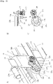
- Fig. 2A is an enlarged perspective view of a region surrounded by a circle in Fig. 1
- Fig. 2B is a plan view illustrating a configuration near a roller of the anti-bounce roller unit shown in Fig. 1
- Fig. 2C is a side view illustrating a configuration near the roller of the anti-bounce roller unit shown in Fig. 1 .
- the bracket 17 has a pair of levers 23a, 23b at exterior surfaces of both sides thereof.
- Each of the levers 23a, 23b is attached to the bracket 17 by screws 24 so as to be rotatable around one end thereof.
- a roller 25a, 25b is attached to the other end of each of the levers 23a, 23b so as to be rotatable around a horizontal axis 26 extending at a right angle to the conveying direction (arrow X) on the associated conveyor belt 7.
- a torsion spring 27 is arranged between the screw 24 and the lever 23a, 23b so as to elastically bias the lever 23a, 23b in a direction that the roller 25a, 25b is pressed against the conveyor belt 7.
- the strength of pressure of roller 25a, 25b against the conveyor belt 7 can be adjusted by adjustment of tightening force of the screw 24.
- a disc 28 to be detected is fixed concentrically to an end face of one roller 25b of the rollers 25a, 25b which faces the associated lever 23b.
- the disc 28 to be detected is composed of a disc-shaped body 28a, and a plurality of protrusions 28b formed at regular intervals on an outer periphery of the disc-shaped body 28a.
- a proximity sensor 29 is fixed on a surface of the lever 23b which faces the disc 28 to be detected and corresponds to the protrusions 28b so as to detect the protrusions 28b.
- the protrusions 28b of the disc 28 to be detected are sequentially detected by the proximity sensor 29 and a detection signal as pulse signals is output from the proximity sensor 29, and a rotational speed of the roller 25b can be detected by monitoring these pulse signals.
- a pair of guide plates 30a, 30b is attached to the frame F and extends in the conveying direction (arrow X) on both sides of the opening 13 above the conveying path 1.
- the sheet S is conveyed to the folding position P while passing through a gap between the conveying path 1 and lower ends of the guide plates 30a, 30b.
- the knife-type folding machine can switch operation between a normal operation mode and a setting mode.
- the plurality of conveyor belts 7 of the conveying unit 2 are continuously rotated at a constant speed so that the sheet S is conveyed to the folding position P and positioned at the folding position P while the knife-type folding unit 4 is kept on a standby state in which the knife blade 11 remains in the first position).
- the knife-type folding machine further comprises a roller rotational speed monitoring unit 31 receiving the detection signal from the proximity sensor 29 and sending an appropriate position arrival signal when the rotational speed of the roller 25b starts to change in the setting mode, and a roller position setting unit 32 operatively connected to the motor 22 of the anti-bounce roller unit 16 and activating the motor 22 (and the threaded shaft 21) in the setting mode so as to move the roller 25b from an upstream or a downstream of a tail end of the sheet S positioned at the folding position P toward the tail end at a constant speed and stopping the motor 22 (and the threaded shaft 21) when the roller position setting unit 32 receives the appropriate position arrival signal.
- roller rotational speed monitoring unit 31 and the roller position setting unit 32 will be explained in detail.
- Figs. 3A through 3D are side views illustrating a method of position setting of the roller 25b of the anti-bounce roller unit 16 of the knife-type folding machine of the present invention during operation in the setting mode.
- the roller position setting unit 32 activates the motor 22 (and the threaded shaft 21) so as to move the roller 25b from an upstream of a tail end of the sheet S positioned at the folding position P (see, Fig. 3A ) toward the tail end at a constant speed.
- the roller 25b From the time the roller 25b starts moving until the roller 25b contacts with the tail end of the sheet S, the roller 25b contacts with the conveyor belt 7 rotated at a constant speed so that the roller 25b rotates at a constant rotational speed according to the difference between the movement speed of the roller 25b and the rotational speed of the conveyor belt 7. Consequently, during this time, the proximity sensor 29 outputs pulse signals (detection signal) with constant frequency.
- the appropriate position arrival signal is received by the roller position setting unit 32 and the roller position setting unit 32 stops the motor 22 (and threaded shaft 21).
- the outer surface of the roller 25b contacts adequately with the tail end of the sheet S positioned at the folding position P.
- the roller position setting unit 32 activates the motor 22 (and the threaded shaft 21) so as to move the roller 25b from a downstream of the tail end of the sheet S positioned at the folding position P (see, Fig. 3C ) toward the tail end at a constant speed.
- the roller 25b From the time the roller 25b starts moving until the roller 25b comes down on the conveyor belt 7, the roller 25b contacts with the sheet S which is at rest so that the roller 25b rotates at a constant rotational speed according to the movement speed of the roller 25b. Consequently, during this time, the proximity sensor 29 outputs pulse signals (detection signal) with constant frequency.
- the appropriate position arrival signal is received by the roller position setting unit 32 and the roller position setting unit 32 stops the motor 22 (and threaded shaft 21).
- the outer surface of the roller 25b contacts adequately with the tail end of the sheet S positioned at the folding position P.
- the sheet S is accurately positioned by the stopper 3and the pair of side guides 33a, 33b and does not tilt with respect to the stopper 3 when the sheet S is inserted between the pair of folding rollers 12a, 12b by the knife blade 11.
- the setting of the roller 25b of the anti-bounce roller unit 16 is carried out automatically so that work efficiency greatly improved.
- the sensor for detecting the rotational speed of the roller 25b of the anti-bounce roller unit 16 is composed of the disc 28 to be detected and the proximity sensor 29 in the above embodiment
- the sensor for detecting the rotational speed of the roller 25b may comprise a disc to be detected fixed concentrically to one end face of the roller 25b, a plurality of through holes being formed on the disc to be detected at a constant angular pitch along a circumference of the disc to be detected, and a pair of photoelectric elements attached to the roller support in such a way that the photoelectric elements are arranged opposite each other across the through holes.
- the sensor for detecting the rotational speed of the roller 25b may be a rotary encoder or a potentiometer attached to the rotation axis of the roller 25b.
- the roller rotational speed monitoring unit 31 comprises a display showing the rotational speed of the roller 25b and a button for transmitting the appropriate position arrival signal. Then an operator monitors changes in the rotational speed of the roller 25b while watching the display, and, when the rotational speed changes, he pushes the button so as to send the appropriate position arrival signal to the roller position setting unit 32.
- the setting of the roller 25b of the anti-bounce roller unit 16 is semiautomated.
Landscapes
- Folding Of Thin Sheet-Like Materials, Special Discharging Devices, And Others (AREA)
Applications Claiming Priority (1)
| Application Number | Priority Date | Filing Date | Title |
|---|---|---|---|
| JP2018202498A JP7146255B2 (ja) | 2018-10-29 | 2018-10-29 | ナイフ折り機 |
Publications (2)
| Publication Number | Publication Date |
|---|---|
| EP3647244A1 EP3647244A1 (en) | 2020-05-06 |
| EP3647244B1 true EP3647244B1 (en) | 2022-10-19 |
Family
ID=68392749
Family Applications (1)
| Application Number | Title | Priority Date | Filing Date |
|---|---|---|---|
| EP19205900.4A Active EP3647244B1 (en) | 2018-10-29 | 2019-10-29 | Knife-type folding machine |
Country Status (4)
| Country | Link |
|---|---|
| US (1) | US11180339B2 (https=) |
| EP (1) | EP3647244B1 (https=) |
| JP (1) | JP7146255B2 (https=) |
| CN (1) | CN111099424B (https=) |
Family Cites Families (15)
| Publication number | Priority date | Publication date | Assignee | Title |
|---|---|---|---|---|
| GB191324301A (en) * | 1913-10-27 | 1914-08-27 | Cleveland Folding Mach Co | Improvements in Paper Folding Machines. |
| DE1561159A1 (de) * | 1966-07-01 | 1970-02-26 | Guenter Mattka | Bogenfalzmaschine |
| DE4131314A1 (de) * | 1991-09-20 | 1993-03-25 | Meteor Siegen Apparat Schmeck | Faltanlage fuer bogenfoermiges faltgut |
| DE4315095A1 (de) * | 1993-05-06 | 1994-11-10 | Stahl Gmbh & Co Maschf | Verfahren zum Betreiben einer Falzmaschine |
| DE19606821A1 (de) * | 1996-02-23 | 1997-08-28 | Boewe Systec Ag | Schwertfalzwerk |
| DE29904757U1 (de) * | 1999-03-16 | 1999-06-17 | Heidelberger Druckmaschinen Ag, 69115 Heidelberg | Falzmaschine mit Niederhalteeinrichtung |
| DE19931768A1 (de) | 1999-07-08 | 2001-01-11 | Schaeffler Waelzlager Ohg | Transportvorrichtung |
| JP3433800B2 (ja) * | 2000-10-04 | 2003-08-04 | 株式会社東京機械製作所 | 輪転機のチョッパー折り装置 |
| DE10119415A1 (de) | 2001-04-20 | 2002-10-24 | Heidelberger Druckmasch Ag | Schwertfalzwerk mit durchgehendem Vorderkantenanschlag und verstellbaren Seitenkantenanschlägen |
| DE20307172U1 (de) * | 2003-05-08 | 2003-07-10 | Maschinenbau Oppenweiler Binder GmbH & Co. KG, 71570 Oppenweiler | Schwertfalzwerk |
| JP4302706B2 (ja) * | 2006-03-28 | 2009-07-29 | ホリゾン・インターナショナル株式会社 | 紙折装置 |
| DE102006042880A1 (de) | 2006-09-13 | 2008-03-27 | Heidelberger Druckmaschinen Ag | Vorrichtung zum Positionieren einer Hinterkante von Bogen |
| DE102009020362A1 (de) * | 2009-05-07 | 2010-11-11 | Heidelberger Druckmaschinen Ag | Vorrichtung zum Positionieren von Bogen in einer Falzmaschine |
| WO2011086700A1 (ja) | 2010-01-18 | 2011-07-21 | ホリゾン・インターナショナル株式会社 | ナイフ折り装置 |
| CN104925577A (zh) * | 2014-03-17 | 2015-09-23 | 柯尼卡美能达办公系统研发(无锡)有限公司 | 折纸机构、纸张后处理装置、成册系统 |
-
2018
- 2018-10-29 JP JP2018202498A patent/JP7146255B2/ja active Active
-
2019
- 2019-10-21 US US16/658,205 patent/US11180339B2/en active Active
- 2019-10-28 CN CN201911031281.6A patent/CN111099424B/zh active Active
- 2019-10-29 EP EP19205900.4A patent/EP3647244B1/en active Active
Also Published As
| Publication number | Publication date |
|---|---|
| CN111099424B (zh) | 2022-12-30 |
| JP2020070111A (ja) | 2020-05-07 |
| CN111099424A (zh) | 2020-05-05 |
| US11180339B2 (en) | 2021-11-23 |
| JP7146255B2 (ja) | 2022-10-04 |
| EP3647244A1 (en) | 2020-05-06 |
| US20200130981A1 (en) | 2020-04-30 |
Similar Documents
| Publication | Publication Date | Title |
|---|---|---|
| JP6198313B2 (ja) | 回転式打抜機 | |
| JP6161120B2 (ja) | ミシン目加工装置 | |
| US11511450B2 (en) | Slicing machine with product recognition device | |
| EP3640172B1 (en) | Knife-type folding machine | |
| US11254120B2 (en) | Conveyance device and image inspection device | |
| US7344016B2 (en) | Method and device for orienting flat items of mail towards a narrow edge | |
| EP3647244B1 (en) | Knife-type folding machine | |
| US5752593A (en) | Belt feeder centering method and apparatus | |
| JP6198314B2 (ja) | ミシン目加工装置 | |
| JP2000313518A (ja) | ベルトコンベア装置 | |
| US20080230984A1 (en) | Sheet material stacking apparatus and method of stacking sheet material | |
| US20250073938A1 (en) | Slicing machine, in particular slicer, and method | |
| JP5534532B2 (ja) | ナイフ折り装置 | |
| US11180338B2 (en) | Veneer moving apparatus | |
| US6860481B2 (en) | Sheet stacking device | |
| US4867437A (en) | Method and apparatus for stacking sheet articles in their original order in a selected one of a pair of hoppers | |
| CN109311614B (zh) | 用于检测片材元件加工机中双片材的检测系统和片材元件加工机 | |
| EP3592680B1 (en) | Document scanner with automated document alignment system | |
| JP2553762Y2 (ja) | スライス装置用原木ガイド装置 | |
| JP2014201382A (ja) | シート搬送装置 | |
| JP6188142B2 (ja) | ミシン目加工装置 | |
| JPH0745287Y2 (ja) | ベニヤ単板切断装置 | |
| JPH08301486A (ja) | 検出装置 | |
| JPH0542667A (ja) | 巻取材料のエツジ位置制御機構のための自己診断装置 | |
| JP2016155611A (ja) | 連続用紙処理装置及び連続用紙処理方法 |
Legal Events
| Date | Code | Title | Description |
|---|---|---|---|
| PUAI | Public reference made under article 153(3) epc to a published international application that has entered the european phase |
Free format text: ORIGINAL CODE: 0009012 |
|
| STAA | Information on the status of an ep patent application or granted ep patent |
Free format text: STATUS: THE APPLICATION HAS BEEN PUBLISHED |
|
| AK | Designated contracting states |
Kind code of ref document: A1 Designated state(s): AL AT BE BG CH CY CZ DE DK EE ES FI FR GB GR HR HU IE IS IT LI LT LU LV MC MK MT NL NO PL PT RO RS SE SI SK SM TR |
|
| AX | Request for extension of the european patent |
Extension state: BA ME |
|
| STAA | Information on the status of an ep patent application or granted ep patent |
Free format text: STATUS: REQUEST FOR EXAMINATION WAS MADE |
|
| 17P | Request for examination filed |
Effective date: 20200706 |
|
| RBV | Designated contracting states (corrected) |
Designated state(s): AL AT BE BG CH CY CZ DE DK EE ES FI FR GB GR HR HU IE IS IT LI LT LU LV MC MK MT NL NO PL PT RO RS SE SI SK SM TR |
|
| GRAP | Despatch of communication of intention to grant a patent |
Free format text: ORIGINAL CODE: EPIDOSNIGR1 |
|
| STAA | Information on the status of an ep patent application or granted ep patent |
Free format text: STATUS: GRANT OF PATENT IS INTENDED |
|
| INTG | Intention to grant announced |
Effective date: 20220531 |
|
| GRAS | Grant fee paid |
Free format text: ORIGINAL CODE: EPIDOSNIGR3 |
|
| GRAA | (expected) grant |
Free format text: ORIGINAL CODE: 0009210 |
|
| STAA | Information on the status of an ep patent application or granted ep patent |
Free format text: STATUS: THE PATENT HAS BEEN GRANTED |
|
| AK | Designated contracting states |
Kind code of ref document: B1 Designated state(s): AL AT BE BG CH CY CZ DE DK EE ES FI FR GB GR HR HU IE IS IT LI LT LU LV MC MK MT NL NO PL PT RO RS SE SI SK SM TR |
|
| REG | Reference to a national code |
Ref country code: GB Ref legal event code: FG4D |
|
| REG | Reference to a national code |
Ref country code: CH Ref legal event code: EP |
|
| REG | Reference to a national code |
Ref country code: DE Ref legal event code: R096 Ref document number: 602019020756 Country of ref document: DE |
|
| REG | Reference to a national code |
Ref country code: IE Ref legal event code: FG4D |
|
| REG | Reference to a national code |
Ref country code: AT Ref legal event code: REF Ref document number: 1525437 Country of ref document: AT Kind code of ref document: T Effective date: 20221115 |
|
| REG | Reference to a national code |
Ref country code: LT Ref legal event code: MG9D |
|
| REG | Reference to a national code |
Ref country code: NL Ref legal event code: MP Effective date: 20221019 |
|
| REG | Reference to a national code |
Ref country code: AT Ref legal event code: MK05 Ref document number: 1525437 Country of ref document: AT Kind code of ref document: T Effective date: 20221019 |
|
| PG25 | Lapsed in a contracting state [announced via postgrant information from national office to epo] |
Ref country code: NL Free format text: LAPSE BECAUSE OF FAILURE TO SUBMIT A TRANSLATION OF THE DESCRIPTION OR TO PAY THE FEE WITHIN THE PRESCRIBED TIME-LIMIT Effective date: 20221019 |
|
| PG25 | Lapsed in a contracting state [announced via postgrant information from national office to epo] |
Ref country code: SE Free format text: LAPSE BECAUSE OF FAILURE TO SUBMIT A TRANSLATION OF THE DESCRIPTION OR TO PAY THE FEE WITHIN THE PRESCRIBED TIME-LIMIT Effective date: 20221019 Ref country code: PT Free format text: LAPSE BECAUSE OF FAILURE TO SUBMIT A TRANSLATION OF THE DESCRIPTION OR TO PAY THE FEE WITHIN THE PRESCRIBED TIME-LIMIT Effective date: 20230220 Ref country code: NO Free format text: LAPSE BECAUSE OF FAILURE TO SUBMIT A TRANSLATION OF THE DESCRIPTION OR TO PAY THE FEE WITHIN THE PRESCRIBED TIME-LIMIT Effective date: 20230119 Ref country code: LT Free format text: LAPSE BECAUSE OF FAILURE TO SUBMIT A TRANSLATION OF THE DESCRIPTION OR TO PAY THE FEE WITHIN THE PRESCRIBED TIME-LIMIT Effective date: 20221019 Ref country code: FI Free format text: LAPSE BECAUSE OF FAILURE TO SUBMIT A TRANSLATION OF THE DESCRIPTION OR TO PAY THE FEE WITHIN THE PRESCRIBED TIME-LIMIT Effective date: 20221019 Ref country code: ES Free format text: LAPSE BECAUSE OF FAILURE TO SUBMIT A TRANSLATION OF THE DESCRIPTION OR TO PAY THE FEE WITHIN THE PRESCRIBED TIME-LIMIT Effective date: 20221019 Ref country code: AT Free format text: LAPSE BECAUSE OF FAILURE TO SUBMIT A TRANSLATION OF THE DESCRIPTION OR TO PAY THE FEE WITHIN THE PRESCRIBED TIME-LIMIT Effective date: 20221019 |
|
| PG25 | Lapsed in a contracting state [announced via postgrant information from national office to epo] |
Ref country code: RS Free format text: LAPSE BECAUSE OF FAILURE TO SUBMIT A TRANSLATION OF THE DESCRIPTION OR TO PAY THE FEE WITHIN THE PRESCRIBED TIME-LIMIT Effective date: 20221019 Ref country code: PL Free format text: LAPSE BECAUSE OF FAILURE TO SUBMIT A TRANSLATION OF THE DESCRIPTION OR TO PAY THE FEE WITHIN THE PRESCRIBED TIME-LIMIT Effective date: 20221019 Ref country code: LV Free format text: LAPSE BECAUSE OF FAILURE TO SUBMIT A TRANSLATION OF THE DESCRIPTION OR TO PAY THE FEE WITHIN THE PRESCRIBED TIME-LIMIT Effective date: 20221019 Ref country code: IS Free format text: LAPSE BECAUSE OF FAILURE TO SUBMIT A TRANSLATION OF THE DESCRIPTION OR TO PAY THE FEE WITHIN THE PRESCRIBED TIME-LIMIT Effective date: 20230219 Ref country code: HR Free format text: LAPSE BECAUSE OF FAILURE TO SUBMIT A TRANSLATION OF THE DESCRIPTION OR TO PAY THE FEE WITHIN THE PRESCRIBED TIME-LIMIT Effective date: 20221019 Ref country code: GR Free format text: LAPSE BECAUSE OF FAILURE TO SUBMIT A TRANSLATION OF THE DESCRIPTION OR TO PAY THE FEE WITHIN THE PRESCRIBED TIME-LIMIT Effective date: 20230120 |
|
| REG | Reference to a national code |
Ref country code: CH Ref legal event code: PL |
|
| REG | Reference to a national code |
Ref country code: BE Ref legal event code: MM Effective date: 20221031 |
|
| PG25 | Lapsed in a contracting state [announced via postgrant information from national office to epo] |
Ref country code: LU Free format text: LAPSE BECAUSE OF NON-PAYMENT OF DUE FEES Effective date: 20221029 |
|
| REG | Reference to a national code |
Ref country code: DE Ref legal event code: R097 Ref document number: 602019020756 Country of ref document: DE |
|
| PG25 | Lapsed in a contracting state [announced via postgrant information from national office to epo] |
Ref country code: SM Free format text: LAPSE BECAUSE OF FAILURE TO SUBMIT A TRANSLATION OF THE DESCRIPTION OR TO PAY THE FEE WITHIN THE PRESCRIBED TIME-LIMIT Effective date: 20221019 Ref country code: RO Free format text: LAPSE BECAUSE OF FAILURE TO SUBMIT A TRANSLATION OF THE DESCRIPTION OR TO PAY THE FEE WITHIN THE PRESCRIBED TIME-LIMIT Effective date: 20221019 Ref country code: MC Free format text: LAPSE BECAUSE OF FAILURE TO SUBMIT A TRANSLATION OF THE DESCRIPTION OR TO PAY THE FEE WITHIN THE PRESCRIBED TIME-LIMIT Effective date: 20221019 Ref country code: LI Free format text: LAPSE BECAUSE OF NON-PAYMENT OF DUE FEES Effective date: 20221031 Ref country code: EE Free format text: LAPSE BECAUSE OF FAILURE TO SUBMIT A TRANSLATION OF THE DESCRIPTION OR TO PAY THE FEE WITHIN THE PRESCRIBED TIME-LIMIT Effective date: 20221019 Ref country code: DK Free format text: LAPSE BECAUSE OF FAILURE TO SUBMIT A TRANSLATION OF THE DESCRIPTION OR TO PAY THE FEE WITHIN THE PRESCRIBED TIME-LIMIT Effective date: 20221019 Ref country code: CZ Free format text: LAPSE BECAUSE OF FAILURE TO SUBMIT A TRANSLATION OF THE DESCRIPTION OR TO PAY THE FEE WITHIN THE PRESCRIBED TIME-LIMIT Effective date: 20221019 Ref country code: CH Free format text: LAPSE BECAUSE OF NON-PAYMENT OF DUE FEES Effective date: 20221031 |
|
| PLBE | No opposition filed within time limit |
Free format text: ORIGINAL CODE: 0009261 |
|
| STAA | Information on the status of an ep patent application or granted ep patent |
Free format text: STATUS: NO OPPOSITION FILED WITHIN TIME LIMIT |
|
| PG25 | Lapsed in a contracting state [announced via postgrant information from national office to epo] |
Ref country code: SK Free format text: LAPSE BECAUSE OF FAILURE TO SUBMIT A TRANSLATION OF THE DESCRIPTION OR TO PAY THE FEE WITHIN THE PRESCRIBED TIME-LIMIT Effective date: 20221019 Ref country code: AL Free format text: LAPSE BECAUSE OF FAILURE TO SUBMIT A TRANSLATION OF THE DESCRIPTION OR TO PAY THE FEE WITHIN THE PRESCRIBED TIME-LIMIT Effective date: 20221019 |
|
| 26N | No opposition filed |
Effective date: 20230720 |
|
| PG25 | Lapsed in a contracting state [announced via postgrant information from national office to epo] |
Ref country code: BE Free format text: LAPSE BECAUSE OF NON-PAYMENT OF DUE FEES Effective date: 20221031 |
|
| PG25 | Lapsed in a contracting state [announced via postgrant information from national office to epo] |
Ref country code: IE Free format text: LAPSE BECAUSE OF NON-PAYMENT OF DUE FEES Effective date: 20221029 |
|
| PG25 | Lapsed in a contracting state [announced via postgrant information from national office to epo] |
Ref country code: SI Free format text: LAPSE BECAUSE OF FAILURE TO SUBMIT A TRANSLATION OF THE DESCRIPTION OR TO PAY THE FEE WITHIN THE PRESCRIBED TIME-LIMIT Effective date: 20221019 |
|
| PG25 | Lapsed in a contracting state [announced via postgrant information from national office to epo] |
Ref country code: HU Free format text: LAPSE BECAUSE OF FAILURE TO SUBMIT A TRANSLATION OF THE DESCRIPTION OR TO PAY THE FEE WITHIN THE PRESCRIBED TIME-LIMIT; INVALID AB INITIO Effective date: 20191029 |
|
| PG25 | Lapsed in a contracting state [announced via postgrant information from national office to epo] |
Ref country code: CY Free format text: LAPSE BECAUSE OF FAILURE TO SUBMIT A TRANSLATION OF THE DESCRIPTION OR TO PAY THE FEE WITHIN THE PRESCRIBED TIME-LIMIT Effective date: 20221019 |
|
| PG25 | Lapsed in a contracting state [announced via postgrant information from national office to epo] |
Ref country code: MK Free format text: LAPSE BECAUSE OF FAILURE TO SUBMIT A TRANSLATION OF THE DESCRIPTION OR TO PAY THE FEE WITHIN THE PRESCRIBED TIME-LIMIT Effective date: 20221019 Ref country code: IT Free format text: LAPSE BECAUSE OF FAILURE TO SUBMIT A TRANSLATION OF THE DESCRIPTION OR TO PAY THE FEE WITHIN THE PRESCRIBED TIME-LIMIT Effective date: 20221019 |
|
| PG25 | Lapsed in a contracting state [announced via postgrant information from national office to epo] |
Ref country code: TR Free format text: LAPSE BECAUSE OF FAILURE TO SUBMIT A TRANSLATION OF THE DESCRIPTION OR TO PAY THE FEE WITHIN THE PRESCRIBED TIME-LIMIT Effective date: 20221019 |
|
| PG25 | Lapsed in a contracting state [announced via postgrant information from national office to epo] |
Ref country code: BG Free format text: LAPSE BECAUSE OF FAILURE TO SUBMIT A TRANSLATION OF THE DESCRIPTION OR TO PAY THE FEE WITHIN THE PRESCRIBED TIME-LIMIT Effective date: 20221019 |
|
| PG25 | Lapsed in a contracting state [announced via postgrant information from national office to epo] |
Ref country code: MT Free format text: LAPSE BECAUSE OF FAILURE TO SUBMIT A TRANSLATION OF THE DESCRIPTION OR TO PAY THE FEE WITHIN THE PRESCRIBED TIME-LIMIT Effective date: 20221019 |
|
| PGFP | Annual fee paid to national office [announced via postgrant information from national office to epo] |
Ref country code: DE Payment date: 20251021 Year of fee payment: 7 |
|
| PGFP | Annual fee paid to national office [announced via postgrant information from national office to epo] |
Ref country code: GB Payment date: 20251022 Year of fee payment: 7 |
|
| PGFP | Annual fee paid to national office [announced via postgrant information from national office to epo] |
Ref country code: FR Payment date: 20251030 Year of fee payment: 7 |