EP3647166A1 - Trailer with double hinge tailgate - Google Patents
Trailer with double hinge tailgate Download PDFInfo
- Publication number
- EP3647166A1 EP3647166A1 EP19206476.4A EP19206476A EP3647166A1 EP 3647166 A1 EP3647166 A1 EP 3647166A1 EP 19206476 A EP19206476 A EP 19206476A EP 3647166 A1 EP3647166 A1 EP 3647166A1
- Authority
- EP
- European Patent Office
- Prior art keywords
- pillar
- latching member
- actuator
- latching
- opening
- Prior art date
- Legal status (The legal status is an assumption and is not a legal conclusion. Google has not performed a legal analysis and makes no representation as to the accuracy of the status listed.)
- Withdrawn
Links
- 230000000717 retained effect Effects 0.000 claims abstract description 4
- 230000013011 mating Effects 0.000 description 3
- 230000006835 compression Effects 0.000 description 1
- 238000007906 compression Methods 0.000 description 1
- 230000000694 effects Effects 0.000 description 1
- 238000000926 separation method Methods 0.000 description 1
- 239000007787 solid Substances 0.000 description 1
- 239000011343 solid material Substances 0.000 description 1
Images


Classifications
-
- B—PERFORMING OPERATIONS; TRANSPORTING
- B62—LAND VEHICLES FOR TRAVELLING OTHERWISE THAN ON RAILS
- B62D—MOTOR VEHICLES; TRAILERS
- B62D33/00—Superstructures for load-carrying vehicles
- B62D33/02—Platforms; Open load compartments
- B62D33/023—Sideboard or tailgate structures
- B62D33/027—Sideboard or tailgate structures movable
- B62D33/037—Latching means therefor
-
- B—PERFORMING OPERATIONS; TRANSPORTING
- B60—VEHICLES IN GENERAL
- B60P—VEHICLES ADAPTED FOR LOAD TRANSPORTATION OR TO TRANSPORT, TO CARRY, OR TO COMPRISE SPECIAL LOADS OR OBJECTS
- B60P1/00—Vehicles predominantly for transporting loads and modified to facilitate loading, consolidating the load, or unloading
- B60P1/04—Vehicles predominantly for transporting loads and modified to facilitate loading, consolidating the load, or unloading with a tipping movement of load-transporting element
- B60P1/26—Means for controlling movement of tailboards or sideboards
-
- E—FIXED CONSTRUCTIONS
- E05—LOCKS; KEYS; WINDOW OR DOOR FITTINGS; SAFES
- E05D—HINGES OR SUSPENSION DEVICES FOR DOORS, WINDOWS OR WINGS
- E05D15/00—Suspension arrangements for wings
- E05D15/48—Suspension arrangements for wings allowing alternative movements
- E05D15/50—Suspension arrangements for wings allowing alternative movements for opening at either of two opposite edges
- E05D15/505—Suspension arrangements for wings allowing alternative movements for opening at either of two opposite edges by radial separation of the hinge parts at the hinge axis
-
- B—PERFORMING OPERATIONS; TRANSPORTING
- B62—LAND VEHICLES FOR TRAVELLING OTHERWISE THAN ON RAILS
- B62D—MOTOR VEHICLES; TRAILERS
- B62D33/00—Superstructures for load-carrying vehicles
- B62D33/02—Platforms; Open load compartments
- B62D33/023—Sideboard or tailgate structures
- B62D33/027—Sideboard or tailgate structures movable
- B62D33/0273—Movable tailboards for vehicles comprising non-movable sideboards, e.g. pick-up trucks
-
- E—FIXED CONSTRUCTIONS
- E05—LOCKS; KEYS; WINDOW OR DOOR FITTINGS; SAFES
- E05Y—INDEXING SCHEME ASSOCIATED WITH SUBCLASSES E05D AND E05F, RELATING TO CONSTRUCTION ELEMENTS, ELECTRIC CONTROL, POWER SUPPLY, POWER SIGNAL OR TRANSMISSION, USER INTERFACES, MOUNTING OR COUPLING, DETAILS, ACCESSORIES, AUXILIARY OPERATIONS NOT OTHERWISE PROVIDED FOR, APPLICATION THEREOF
- E05Y2900/00—Application of doors, windows, wings or fittings thereof
- E05Y2900/50—Application of doors, windows, wings or fittings thereof for vehicles
- E05Y2900/53—Type of wing
- E05Y2900/544—Tailboards, tailgates or sideboards opening downwards
Definitions
- the present invention relates to trailers and more particularly to improvements in relation to hinge arrangements to allow trailer panels such as tailgates to be hinged about 2 different axes.
- So called box trailers are a type of trailer well known in the art which have a chassis on which is supported a trailer base with four side panel upstanding from the base, each side panel extending between a pair of adjacent corner pillars, to form a cubic enclosure around the base. It is common for at least one of the side panels, typically the rear end or tailgate panel, to have a hinge connection to the trailer to enable the panel to be folded down to facilitate loading and unloading.
- the support side pillars for the hinging panel furthermore include an upper hinge jaw, the upper hinge jaws being aligned with each other on a common axis which defines an upper hinge axis between the side pillars, and a lower hinge, the lower hinge jaws being aligned with each other on a common axis which defines a lower hinge axis between the side pillars.
- the upper and lower hinge jaws are spaced from each other to match the spacing of the upper and lower hinge posts of the panel such that when the hinging panel is engaged to extend between the side pillars, each of the upper hinge posts of the panel engages in a respective one of the upper hinge jaws, and each of the lower hinge posts of the panel engages in a respective one of the lower hinge jaws.
- Retainers such as retaining pins, are then engageable in each of the jaws to retain each hinge post in its respective jaw in a manner which allows rotation of the pins within their respective jaws about their longitudinal axis.
- This known system has the drawbacks that it can be difficult and fiddly for a person to release and re-secure the hinging panel alone due to the need to remove and re-fit the retaining pins at opposing sides of the panel. Furthermore, there is the risk of losing the retaining pins or their being stolen, and the fit of the posts within the jaws is typically quite loose, leading to significant rattling during use of the trailer.
- a mounting pillar for a double hinging trailer panel the pillar being an elongated member which extends longitudinally between first and second ends, the pillar having a first transverse opening formed in its outer surface proximate the first end and a second transverse opening formed in its outer surface proximate the second end, each of said openings extending at least partially across the width of the pillar and being sufficiently wide and deep such that, in use, the entire transverse periphery of a hinge post of a trailer panel is fully engageable in each opening, the pillar further comprising a first latching member associated with the first transverse opening and a second latching member associated with the second transverse opening, each of said first and second latching members being moveable longitudinally along the pillar between first and second positions, and each of the latching members having an opening formed therein and a retaining hook which forms an undercut which connects to the opening, wherein in the first position of each latching member, the opening is aligned with the associated
- a mounting pillar according to the present invention has the advantage that it provides a self contained, releasable hinge point at both the top and the bottom of the pillar which are easily opened and closed by operation of a common actuator and which operate in opposite senses so that only one can be opened at a time.
- This enables a trailer panel, such as a tailgate, to be operated in either a top hinging or a bottom hinging configuration in a particularly straightforward manner which does not require separation of parts which could become lost.
- each transverse opening extends across the entire width of the pillar so that a hinge post engages therein protrudes from either side of the pillar.
- each transverse opening may instead extending only partially across the width of the pillar so that an end of a hinge post engaged in the transverse opening is housed within the transverse opening.
- the Pillar is preferably tubular with the latching members and actuator being housed inside the pillar.
- the latching members and actuator may be formed as sleeves which locate on the outside of the pillar, in which case the pillar need not be tubular.
- Each latching member preferably has biasing means associated with it which biases it into its second position, operation of the actuator moving the respective latching member from its second position to its first position against the loading of the biasing means.
- biasing means may be provided for each latching member, but in a preferred embodiment, a single biasing means operates on both latching members.
- the biasing means comprises a spring which is attached, preferably hooked at each end, to both the first and second latching member and acts to urge them towards each other, operation of the actuator moving a respective one of the latching members away from the other of the latching members and into its first position.
- the actuator is located between the first and second latching members, the biasing means urging the first and second latching members into engagement with opposing ends of the actuator.
- the actuator then preferably includes a lever which protrudes through a slot in the pillar to enable a user to move the actuator longitudinally in the pillar from outside. The slot will then extend longitudinally partially along the pillar from the middle towards each end.
- the actuator is preferably rotatable, at least to a limited degree, within the pillar, and the slot advantageously intersects, at each end, a transverse slot so as to enable the actuator to be rotated once the respective latching member has reached its first position, so as to lock the actuator in place against the biasing force of the biasing means.
- a stop is preferably associated with each latching member to limit its movement towards the opposing latching member.
- Each latching means is preferably configured with the tip of its retaining hook pointing towards the actuator such that each latching member is moved away from the opposing latching member in order to move it into its first position.
- the present invention further provides a trailer having a double hinging trailer panel, comprising a base having a mounting pillar according to the invention provided proximate opposing ends of at one least side of the base, the transverse openings proximate a first end of each pillar being aligned along a common axis which defines a first hinge axis, and the transverse openings proximate a second end of each pillar being aligned along a common axis which defines a second hinge axis.
- the trailer preferably also includes a trailer panel having first and second hinge posts extending from opposing ends of the panel, the hinge posts on each end being spaced to correspond with the spacing between the transverse openings in the mounting pillars of the trailer such that trailer panel is engageable with the at least one side of the base with each of the hinges aligned with one of the transverse openings, the hinge posts being sized to be engageable in said transverse openings in a manner which allows each to rotation in its transverse opening about its longitudinal axis.
- Trailer 1 has a corner pillar 2 on each corner to support the side panels 3 which extend around the base 4.
- the illustrated corner pillar 2 has an upper pair of jaws 5 which form one side of an upper hinge for the panel 3, and a lower pair of jaws 6 which form one side of a lower hinge for the panel 3.
- Each pair of jaws 5, 6 is sufficiently spaced such that a mouth 5a, 6a defined between them is wide and deep enough to enable a hinge post 7 which extends longitudinally from a side of the panel 3 to fully engage transversely of the pillar 2 in the mouth and to be retained therein by a locking pin which is engageable through the jaws to close the mouth 5a, 6a whilst allowing the pin to rotate about its longitudinal axis.
- FIG. 2 to 7 there is shown a double hinging trailer panel assembly embodying the present invention.
- the panel is a back or tailgate panel, which fits onto the back of the trailer, it will be understood that it is equally applicable to other panels and may be implements on multiple panels of the same trailer.
- the tailgate panel 10 itself is similar to panel designs which are used with the prior art system illustrated in Figure 1 , being generally rectilinear in shape with opposing top 11, bottom 12 and side 13 14 edges.
- Each of the side edges 13, 14 has upper 15a and lower 15b hinge posts provided thereon which extend outwardly and away from the side edges parallel to the top and bottom edges 11, 12, the upper hinge posts 15a extending along a common longitudinal axis which defines an upper hinge line, and the lower hinge posts 15b extending along a common longitudinal axis which defines a lower hinge line which is parallel to but spaced apart from the upper hinge line.
- each corner pillar 16 is tubular, and in the illustrated embodiment, square in cross-section, although other cross sectional shapes are possible.
- Each pillar 16 has an upper transverse opening 17 and a lower transverse open 18 provided in its rear side, the openings 17, 18 being spaced longitudinally along the pillar 16 to correspond with the spacing between the upper and lower hinge posts 15a, 15b on the mating panel 10 such that when the panel 10 is engaged with the pillar 16, the upper hinge post 15a locates with the upper transverse opening 17 and the lower hinge post 15b engages with the lower transverse opening 18.
- Each of the transverse openings 17, 18 extends across the entire width of the side in which it is formed and is sufficiently wide and deep to allow the circumference of the mating hinge post 15a, 15b to be fully receiving in the opening 17, 18 so that an retaining hook 19b, 20b, housed within the pillar 16 can engaged between the post 15a, 15b and the mouth of the opening 17, 18 to lock each post 15a, 15b in its associated opening 17, 18 as set out below.
- the opening preferably taper outwardly towards the rear side of the pillar 16 so that they are wider at the mouth, as shown in Figure 4b , to make it easier for a user to locate the hinge posts in the openings 17, 18.
- each pillar 16 Housed within each pillar 16 is pair of latching members - an upper latching member 19 associated with the upper transverse opening 17, and a lower latching member 20 associated with the lower transverse opening 18, as well as an actuator 21 which sits between and is engageable with both the upper latching member 19 and the lower latching member 20.
- Both the latching members 19, 20 and the actuator 21 are slidably moveable longitudinally within the pillar, optionally within stop limits as set out below, and the actuator 21 includes a lever 21a which extends through a slot 23 in the rear side of the pillar and may be used by an operators to slide the actuator up and down within the pillar 16 to effect movement of the latching members 19, 20 to open and close the openings 17, 18 as described below.
- the slot 23 is generally C-shaped, having lateral top and bottom sections extending from the longitudinal main part of the slot, as shown in Figure 4a , and the actuator 21 has a circular cross-section such that it can rotate about the longitudinal axis of the pillar 16. In this way, when the lever 21a reaches the top or bottom of the longitudinal section of the slot 23, it may be moved across into the connecting lateral section in order to hold the actuator 21 in its raised or lowered position against a centring force applied by biasing means described below.
- each of the latching members 19, 20 has an opening 19a, 20a which extends from a side which faces the mouth of the associated transverse opening 17, 18 away from said mouth and then turns 90 degrees and extends behind retaining hook 19b, 20b formed on the latching member 19, 20 to form an undercut region 19c, 20c.
- the openings 19a, 20a are sized to allow the circumference of the hinge posts 15a, 15b to pass therealong.
- the mating hinge post 15a, 15b can be engaged in the tranverse opening 17, 18 of the pillar 16 so as to pass transversely through the pillar 16 and locate in the opening 19a, 20a of the latch member 19, 20.
- the latch member 19, 20 is then moved from its first, open position, to a second, closed position by sliding in a direction to move its retaining hook 19b, 20b into alignment with its associated transverse opening 17, 18 and move the hinge post 15a, 15b into the undercut region 19c, 20c, thereby trapping the hinge post 15a, 15b in the transverse opening 17, 18 so as to prevent it being removed therefrom.
- the side of the undercut region 19c, 20c and transverse opening 17, 18 is such that, when trapped, each hinge post15a, 15b can still rotate within the transverse opening 17, 18 about its longitudinal axis so as to form a hinge for the panel 10.
- the upper and lower latching members 19, 20 are configured in the pillar 16 in opposing sense such that the longitudinal movement of the upper latching member 19 from its open to its closed position is opposite to the longitudinal movement of the lower latching member 20 from its open to its closed position.
- the actuator 21 in order to open the upper latching member 19 it is moved upwards, whereas in order to move the lower latching member 20 it is moved downwards. This is achieved by movement of the actuator 21 in the required direction.
- the actuator locates between the upper and lower latching members 19, 20 with a spring 22 extending between the latching members 19, 20 and through the actuator 21, which spring acts to bias the latching members 19, 20 towards each other and into abutment with the actuator 21 in which they are each in their closed position shown in Figure 4b .
- the actuator 21 IN order to open the upper transverse opening 17, the actuator 21 is moved upwards by the user sliding the lever 21a upwards as shown in Figure 6 . This pushes the upper latching member 19 upwards against the biasing action of the spring 22, lifting the retaining hook 19b away from the upper transverse opening 17 and allowing an upper hinge post 15a to be inserted into or removed from the upper transverse opening 17. If there is already a hinge post 15b engaged in the lower transverse opening 18, it will prevent upwards movement of the lower latching member 20. Otherwise, the lower latching member may optionally be prevented from moving upwards with the upper latching member 19 and the actuator 21, under the loading of the spring 22, by a stop provided on the inside of the pillar 16, or may be allowed to move upwards with the upper latching member 19 and actuator 21.
- a stop may again optionally be provided in the pillar to prevent the upper latching member 19 moving downwards beyond its closed position in the event that there is no hinge post engaged therein during opening of the lower transverse member 18, or the upper latching member 19 may be allowed to move downwards beyond its closed position with the lower latching member 18 and actuator 21 in the event that no hinge post is engaged therein.
- the co-linear arrangement of the pairs of upper and lower hinge posts and the corresponding collinear alignment of upper pairs and lower pairs of transverse openings on pairs of pillars on adjacent corners means that, when the lower hinge posts are released from the lower latching members, the panel 10 is free to hinge about the upper hinge posts and vice-versa. Furthermore, the panel 10 can be completely removed from the trailer by releasing one of the upper and lower hinge posts and then the other of the upper and lower hinge posts.
- the described embodiment has the actuator engaging between the upper and lower latching members, it will be appreciated that other configurations are possible, the important feature being that the movement of the upper latching member from its open to closed positions be in the opposite send to the movement of the lower latching member from its open to closed positions, and vice-versa, so as to ensure that both transverse openings are not opened simultaneously.
- the upper and lower latching members may overlap each other, with one telescoping inside the other or the two having overlapping front and back extension panels.
- Overlapping actuation slots could then be provided in the two latching members through which an actuating lever extends such that, when the level is moved in one direction, it engages the bottom of the slot of one latching member whilst travelling along the other in a lost motion manner, causing only one latching member to move.
- the lever When the lever is moved in the other direction, it engages the bottom of the slot of the other actuating member whilst travelling along the slot of the first, thereby effecting movement of only the other latching member.
- each latching member may be provided for each latching member, which could, for example, engage between the respective biasing member and the actuator, be a compression spring which locates between an end of each latching member and the adjacent end of the pillar to urges the latching member away from said end, between the latching member and another part of the pillar of the like.
- the retaining hook and undercut portions of the latching members may be oriented the other way round so that moving each latching member towards the longitudinal middle of the pillar opens each transverse opening, the biasing means then urging each latching member away from the middle of the pillar.
- each latching member is formed by a pair of spaced apart plates which each have an opening, an undercut region and a retaining hook, the plates being joined at the top and bottom by transverse plates.
- Other designs are, however, also possible such as being formed from solid material.
- each retaining hook which faces away from the undercut region may advantageously be inclined relative to the plane of the rear surface of the pillar such that the tip of the retaining hook is further from the rear surface of the pillar than the base of the hook. This will enable a hinge post pressed against the outer surface of the hook to develop a camming action with the hook, causing it to move away from its closed position towards it open position, against the biasing force of the spring, automatically when the hinge post is pressed against it, thereby making latching of the hinge posts into the transverse openings easier.
Landscapes
- Engineering & Computer Science (AREA)
- Mechanical Engineering (AREA)
- Transportation (AREA)
- Chemical & Material Sciences (AREA)
- Combustion & Propulsion (AREA)
- Body Structure For Vehicles (AREA)
Abstract
A mounting pillar 16 for a trailer panel 10 has first 17 and second 18 transverse openings sized to fully receive a hinge post 15a, 15b of the trailer panel 10 therein. First and second latching members 19, 20 are associated with the transverse openings 17, 18. Each of the latching members 19, 20 is moveable along the pillar 16, and has an opening 19a, 20a and a retaining hook 19b, 20b which forms an undercut 19c, 20c which connects to the opening 19a, 20a. In one position of each latching member 19, 20, the opening 19a, 20a is aligned with the associated pillar transverse opening 17, 18 such that, in use, a hinge post 15a, 15b engaged with its longitudinal axis extending across the transverse opening 17, 18 engages in the opening 19a, 20a in the latching member 19, 20. In another position of each latching member 19, 20, the retaining hook 19b, 20b is aligned with the transverse opening 17, 18 so as to close it. The hinge post 15a, 15b engaged in the transverse opening 17, 18 is thereby retained in the undercut 19c, 20c behind the retaining hook 19b, 20b while being rotatable about its longitudinal axis.
Description
- The present invention relates to trailers and more particularly to improvements in relation to hinge arrangements to allow trailer panels such as tailgates to be hinged about 2 different axes.
- So called box trailers are a type of trailer well known in the art which have a chassis on which is supported a trailer base with four side panel upstanding from the base, each side panel extending between a pair of adjacent corner pillars, to form a cubic enclosure around the base. It is common for at least one of the side panels, typically the rear end or tailgate panel, to have a hinge connection to the trailer to enable the panel to be folded down to facilitate loading and unloading. This is typically achieved by a hinge connection between the bottom edge of the panel and the base, together with posts on the supporting corner pillars which engage through respective apertures in retaining wings provided close to the upper ends of opposing sides of the panel, suitable locking means such as locking pins being engageable through the posts to retain the wings on the posts and hence the panel in the raised position.
- It is further known in the art to provide such trailers with double hinged panels, that is ones which can pivot about either the bottom edge to enable the panel to be folded down for loading and unloading, or about the top edge to enable the panel to be pivoted upwards about its upper edge for allowing unloading of the trailer by tipping. This achieved by providing the hinging panel with a pair of upper hinge posts which extend outwardly away from the upper ends of the side edges of the hinging panel along a common longitudinal axis which defines an upper hinge axis for the panel, and a pair of lower hinge posts which extend outwardly away from the lower ends of the side edges of the hinging panel along a common longitudinal axis which defines a lower hinge axis for the panel. The support side pillars for the hinging panel furthermore include an upper hinge jaw, the upper hinge jaws being aligned with each other on a common axis which defines an upper hinge axis between the side pillars, and a lower hinge, the lower hinge jaws being aligned with each other on a common axis which defines a lower hinge axis between the side pillars. The upper and lower hinge jaws are spaced from each other to match the spacing of the upper and lower hinge posts of the panel such that when the hinging panel is engaged to extend between the side pillars, each of the upper hinge posts of the panel engages in a respective one of the upper hinge jaws, and each of the lower hinge posts of the panel engages in a respective one of the lower hinge jaws. Retainers, such as retaining pins, are then engageable in each of the jaws to retain each hinge post in its respective jaw in a manner which allows rotation of the pins within their respective jaws about their longitudinal axis.
- This known system has the drawbacks that it can be difficult and fiddly for a person to release and re-secure the hinging panel alone due to the need to remove and re-fit the retaining pins at opposing sides of the panel. Furthermore, there is the risk of losing the retaining pins or their being stolen, and the fit of the posts within the jaws is typically quite loose, leading to significant rattling during use of the trailer.
- According to a first aspect of the present invention there is provided a mounting pillar for a double hinging trailer panel, the pillar being an elongated member which extends longitudinally between first and second ends, the pillar having a first transverse opening formed in its outer surface proximate the first end and a second transverse opening formed in its outer surface proximate the second end, each of said openings extending at least partially across the width of the pillar and being sufficiently wide and deep such that, in use, the entire transverse periphery of a hinge post of a trailer panel is fully engageable in each opening, the pillar further comprising a first latching member associated with the first transverse opening and a second latching member associated with the second transverse opening, each of said first and second latching members being moveable longitudinally along the pillar between first and second positions, and each of the latching members having an opening formed therein and a retaining hook which forms an undercut which connects to the opening, wherein in the first position of each latching member, the opening is aligned with the associated transverse opening in the pillar such that, in use, a hinge post engaged with its longitudinal axis extending across the transverse opening engages in the opening in the latching member, and in the second position of each latching member, the retaining hook is aligned with the transverse opening so as to close it whereby a hinge post engaged in the transverse opening is engaged in the undercut behind the retaining hook and is thereby retained in the transverse opening in a manner which allows rotation of the hinge post about its longitudinal axis, and wherein said first and second latching members arranged in opposing orientations such that they move in opposite directions to move from their first to their second positions, and the pillar further including an actuator positioned between said first and second latching members and moveable in a first direction in order to move said first latching member from said second position to said first position and moveable in a second direction in order to move said second latching member from said second position to said first position.
- A mounting pillar according to the present invention has the advantage that it provides a self contained, releasable hinge point at both the top and the bottom of the pillar which are easily opened and closed by operation of a common actuator and which operate in opposite senses so that only one can be opened at a time. This enables a trailer panel, such as a tailgate, to be operated in either a top hinging or a bottom hinging configuration in a particularly straightforward manner which does not require separation of parts which could become lost.
- Preferably, each transverse opening extends across the entire width of the pillar so that a hinge post engages therein protrudes from either side of the pillar. However, each transverse opening may instead extending only partially across the width of the pillar so that an end of a hinge post engaged in the transverse opening is housed within the transverse opening.
- The Pillar is preferably tubular with the latching members and actuator being housed inside the pillar. Alternatively, the latching members and actuator may be formed as sleeves which locate on the outside of the pillar, in which case the pillar need not be tubular.
- Each latching member preferably has biasing means associated with it which biases it into its second position, operation of the actuator moving the respective latching member from its second position to its first position against the loading of the biasing means. Separate biasing means may be provided for each latching member, but in a preferred embodiment, a single biasing means operates on both latching members. IN particular, the biasing means comprises a spring which is attached, preferably hooked at each end, to both the first and second latching member and acts to urge them towards each other, operation of the actuator moving a respective one of the latching members away from the other of the latching members and into its first position.
- Preferably, the actuator is located between the first and second latching members, the biasing means urging the first and second latching members into engagement with opposing ends of the actuator. For configurations in which the latching members and actuator are housed within a tubular pillar, the actuator then preferably includes a lever which protrudes through a slot in the pillar to enable a user to move the actuator longitudinally in the pillar from outside. The slot will then extend longitudinally partially along the pillar from the middle towards each end. The actuator is preferably rotatable, at least to a limited degree, within the pillar, and the slot advantageously intersects, at each end, a transverse slot so as to enable the actuator to be rotated once the respective latching member has reached its first position, so as to lock the actuator in place against the biasing force of the biasing means.
- A stop is preferably associated with each latching member to limit its movement towards the opposing latching member.
- Each latching means is preferably configured with the tip of its retaining hook pointing towards the actuator such that each latching member is moved away from the opposing latching member in order to move it into its first position.
- The present invention further provides a trailer having a double hinging trailer panel, comprising a base having a mounting pillar according to the invention provided proximate opposing ends of at one least side of the base, the transverse openings proximate a first end of each pillar being aligned along a common axis which defines a first hinge axis, and the transverse openings proximate a second end of each pillar being aligned along a common axis which defines a second hinge axis.
- The trailer preferably also includes a trailer panel having first and second hinge posts extending from opposing ends of the panel, the hinge posts on each end being spaced to correspond with the spacing between the transverse openings in the mounting pillars of the trailer such that trailer panel is engageable with the at least one side of the base with each of the hinges aligned with one of the transverse openings, the hinge posts being sized to be engageable in said transverse openings in a manner which allows each to rotation in its transverse opening about its longitudinal axis.
- IN order that the invention may be well understood, there will now be described an embodiment thereof, given by way of example, reference being made to the accompanying drawings, in which:
-
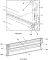
Figure 1 is an view of a hinge configuration for a trailer tailgate known from the prior art; -
Figure 2 is a perspective view of a double hinging trailer panel which forms part of the present invention; -
Figure 3 is a perspective view of one end of the trailer panel ofFigure 2 mounted to a trailer corner pillar of the invention in a closed position; -
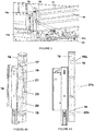
Figures 4a and 4b are transparency perspective and side views of the trailer corner pillar ofFigure 3 in a fully locked position; -
Figure 5 is an exploded side view of a latch mechanism which is housed within the trailer pillar ofFigures 4a and 4b ; -
Figures 6A and 6B are transparency side and solid perspective views of the corner pillar ofFigure 4 in a bottom hinging configuration; -
Figure 7 is a transparency side view of the corner pillar ofFigure 4 in a top hinging configuration; and -
Figure 8 is a perspective view of the corner pillar ofFigure 4 in a fully locked configuration. - Referring first to
Figure 1 , there is a part of a double hinging trailer tailgate arrangement known in the art.Trailer 1 has acorner pillar 2 on each corner to support theside panels 3 which extend around thebase 4. The illustratedcorner pillar 2 has an upper pair ofjaws 5 which form one side of an upper hinge for thepanel 3, and a lower pair ofjaws 6 which form one side of a lower hinge for thepanel 3. Each pair ofjaws mouth hinge post 7 which extends longitudinally from a side of thepanel 3 to fully engage transversely of thepillar 2 in the mouth and to be retained therein by a locking pin which is engageable through the jaws to close themouth - In this way, to enable top opening of the panel, the locking pins in the upper pair of
jaws 5 of theadjacent corner pillars 2 are removed, allowing the upper hinge posts to be released from theupper jaws 5 and thepanel 3 rotated about the hinge created by the engagement of lower hinge posts in between the lower pairs ofjaws 6 provided on theadjacent corner pillars 2. Similarly to enable top hinging of the panel for tipping of the trailer, upper hinge posts are re-engaged between theupper jaws 5 and locked in place, after which lower hinge posts are released from thelower jaws 6 by removing locking pins, thereby allowing the panel to hinge about the upper hinge posts. - Referring next to
Figures 2 to 7 , there is shown a double hinging trailer panel assembly embodying the present invention. Although in the illustrated embodiment the panel is a back or tailgate panel, which fits onto the back of the trailer, it will be understood that it is equally applicable to other panels and may be implements on multiple panels of the same trailer. - The
tailgate panel 10 itself, illustrated inFigure 2 , is similar to panel designs which are used with the prior art system illustrated inFigure 1 , being generally rectilinear in shape with opposing top 11, bottom 12 andside 13 14 edges. Each of the side edges 13, 14 has upper 15a and lower 15b hinge posts provided thereon which extend outwardly and away from the side edges parallel to the top andbottom edges - The
panel 10 mounts in place on the back of the trailer between a pair ofcorner pillars 16 which are secured to the rear corners of the trailer in a suitable manner. As shown inFigures 4a - Figure 5 , eachcorner pillar 16 is tubular, and in the illustrated embodiment, square in cross-section, although other cross sectional shapes are possible. Eachpillar 16 has an uppertransverse opening 17 and a lower transverse open 18 provided in its rear side, theopenings pillar 16 to correspond with the spacing between the upper andlower hinge posts mating panel 10 such that when thepanel 10 is engaged with thepillar 16, theupper hinge post 15a locates with the uppertransverse opening 17 and thelower hinge post 15b engages with the lowertransverse opening 18. Each of thetransverse openings mating hinge post opening hook pillar 16 can engaged between thepost opening post opening pillar 16 so that they are wider at the mouth, as shown inFigure 4b , to make it easier for a user to locate the hinge posts in theopenings - Housed within each
pillar 16 is pair of latching members - anupper latching member 19 associated with the uppertransverse opening 17, and alower latching member 20 associated with the lowertransverse opening 18, as well as anactuator 21 which sits between and is engageable with both the upper latchingmember 19 and thelower latching member 20. Both the latchingmembers actuator 21 are slidably moveable longitudinally within the pillar, optionally within stop limits as set out below, and theactuator 21 includes alever 21a which extends through aslot 23 in the rear side of the pillar and may be used by an operators to slide the actuator up and down within thepillar 16 to effect movement of the latchingmembers openings slot 23 is generally C-shaped, having lateral top and bottom sections extending from the longitudinal main part of the slot, as shown inFigure 4a , and theactuator 21 has a circular cross-section such that it can rotate about the longitudinal axis of thepillar 16. In this way, when thelever 21a reaches the top or bottom of the longitudinal section of theslot 23, it may be moved across into the connecting lateral section in order to hold theactuator 21 in its raised or lowered position against a centring force applied by biasing means described below. - As shown more clearly in
Figure 5 , each of the latchingmembers opening transverse opening hook member region openings hinge posts members opening transverse opening pillar 16, themating hinge post tranverse opening pillar 16 so as to pass transversely through thepillar 16 and locate in theopening latch member transverse opening latch member retaining hook transverse opening hinge post undercut region hinge post transverse opening undercut region transverse opening transverse opening panel 10. - The upper and
lower latching members pillar 16 in opposing sense such that the longitudinal movement of theupper latching member 19 from its open to its closed position is opposite to the longitudinal movement of thelower latching member 20 from its open to its closed position. In particular, in the illustrated embodiment, as shown inFigure 4b , in order to open theupper latching member 19 it is moved upwards, whereas in order to move thelower latching member 20 it is moved downwards. This is achieved by movement of theactuator 21 in the required direction. The actuator locates between the upper andlower latching members spring 22 extending between the latchingmembers actuator 21, which spring acts to bias the latchingmembers actuator 21 in which they are each in their closed position shown inFigure 4b . - IN order to open the upper
transverse opening 17, theactuator 21 is moved upwards by the user sliding thelever 21a upwards as shown inFigure 6 . This pushes the upper latchingmember 19 upwards against the biasing action of thespring 22, lifting the retaininghook 19b away from the uppertransverse opening 17 and allowing anupper hinge post 15a to be inserted into or removed from the uppertransverse opening 17. If there is already ahinge post 15b engaged in the lowertransverse opening 18, it will prevent upwards movement of thelower latching member 20. Otherwise, the lower latching member may optionally be prevented from moving upwards with the upper latchingmember 19 and theactuator 21, under the loading of thespring 22, by a stop provided on the inside of thepillar 16, or may be allowed to move upwards with the upper latchingmember 19 andactuator 21. - When the
actuator lever 22 is released, the tension in the spring will cause the upper latchingmember 19 to move back down into its closed position. The operation is reversed when the lower transverse opening is to be opening, with thelever 22 then being moved downwards rather than upwards. A stop may again optionally be provided in the pillar to prevent the upper latchingmember 19 moving downwards beyond its closed position in the event that there is no hinge post engaged therein during opening of the lowertransverse member 18, or the upper latchingmember 19 may be allowed to move downwards beyond its closed position with thelower latching member 18 andactuator 21 in the event that no hinge post is engaged therein. - As with the prior art systems, the co-linear arrangement of the pairs of upper and lower hinge posts and the corresponding collinear alignment of upper pairs and lower pairs of transverse openings on pairs of pillars on adjacent corners means that, when the lower hinge posts are released from the lower latching members, the
panel 10 is free to hinge about the upper hinge posts and vice-versa. Furthermore, thepanel 10 can be completely removed from the trailer by releasing one of the upper and lower hinge posts and then the other of the upper and lower hinge posts. - Although the described embodiment has the actuator engaging between the upper and lower latching members, it will be appreciated that other configurations are possible, the important feature being that the movement of the upper latching member from its open to closed positions be in the opposite send to the movement of the lower latching member from its open to closed positions, and vice-versa, so as to ensure that both transverse openings are not opened simultaneously. For example, the upper and lower latching members may overlap each other, with one telescoping inside the other or the two having overlapping front and back extension panels. Overlapping actuation slots could then be provided in the two latching members through which an actuating lever extends such that, when the level is moved in one direction, it engages the bottom of the slot of one latching member whilst travelling along the other in a lost motion manner, causing only one latching member to move. When the lever is moved in the other direction, it engages the bottom of the slot of the other actuating member whilst travelling along the slot of the first, thereby effecting movement of only the other latching member.
- Instead of a single biasing spring being provided which extends between the two latching members, a separate spring may be provided for each latching member, which could, for example, engage between the respective biasing member and the actuator, be a compression spring which locates between an end of each latching member and the adjacent end of the pillar to urges the latching member away from said end, between the latching member and another part of the pillar of the like.
- It is also possible that the retaining hook and undercut portions of the latching members may be oriented the other way round so that moving each latching member towards the longitudinal middle of the pillar opens each transverse opening, the biasing means then urging each latching member away from the middle of the pillar.
- In the illustrated embodiment, each latching member is formed by a pair of spaced apart plates which each have an opening, an undercut region and a retaining hook, the plates being joined at the top and bottom by transverse plates. Other designs are, however, also possible such as being formed from solid material.
- The side of each retaining hook which faces away from the undercut region may advantageously be inclined relative to the plane of the rear surface of the pillar such that the tip of the retaining hook is further from the rear surface of the pillar than the base of the hook. This will enable a hinge post pressed against the outer surface of the hook to develop a camming action with the hook, causing it to move away from its closed position towards it open position, against the biasing force of the spring, automatically when the hinge post is pressed against it, thereby making latching of the hinge posts into the transverse openings easier.
Claims (15)
- A mounting pillar for a double hinging trailer panel, the pillar being an elongated member which extends longitudinally between first and second ends, the pillar having a first transverse opening formed in its outer surface proximate the first end and a second transverse opening formed in its outer surface proximate the second end, each of said openings extending at least partially across the width of the pillar and being sufficiently wide and deep such that, in use, the entire cross section of a hinge post of a trailer panel is fully engageable in each opening, the pillar further comprising a first latching member associated with the first transverse opening and a second latching member associated with the second transverse opening, each of said first and second latching members being moveable longitudinally along the pillar between first and second positions, and each of the latching members having an opening formed therein and a retaining hook which forms an undercut which connects to the opening, wherein in the first position of each latching member, the opening is aligned with the associated transverse opening in the pillar such that, in use, a hinge post engaged with its longitudinal axis extending across the transverse opening engages in the opening in the latching member, and in the second position of each latching member, the retaining hook is aligned with the transverse opening so as to close it whereby a hinge post engaged in the transverse opening is engaged in the undercut behind the retaining hook and is thereby retained in the transverse opening in a manner which allows rotation of the hinge post about its longitudinal axis, and wherein said first and second latching members are arranged in opposing orientations such that they move in opposite directions to move from their first to their second positions, and the pillar further including an actuator positioned between said first and second latching members and moveable in a first direction in order to move said first latching member from said second position to said first position and moveable in a second direction in order to move said second latching member from said second position to said first position.
- A mounting pillar according to claim 1, wherein each transverse opening extends across the entire width of the pillar so that a hinge post engages therein protrudes from either side of the pillar.
- A mounting pillar according to claim 1, wherein each transverse opening may instead extending only partially across the width of the pillar so that an end of a hinge post engaged in the transverse opening is housed within the transverse opening.
- A mounting pillar according to any of the preceding claims, wherein the pillar is tubular with the latching members and actuator being housed inside the pillar.
- A mounting pillar according to any of claims 1 to 3, wherein the latching members and actuator are formed as sleeves which locate on the outside of the pillar.
- A mounting pillar according to any of the preceding claims, wherein each latching member has an associated biasing means, the each latching member being biased into its second position by the associated biasing means, operation of the actuator moving the respective latching member from its second position to its first position against the loading of the biasing means.
- A mounting pillar according to claim 6, wherein separate biasing means are provided for each latching member.
- A mounting pillar according to claim 6, wherein a single biasing means operates on both latching members, the biasing means preferably comprising a spring which is attached, preferably hooked at each end, to both the first and second latching member and acts to urge them towards each other, operation of the actuator moving a respective one of the latching members away from the other of the latching members and into its first position.
- A mounting pillar according to any of claims 6 to 8, wherein the actuator is located between the first and second latching members, the biasing means urging the first and second latching members into engagement with opposing ends of the actuator.
- A mounting pillar according to any of the preceding claims, wherein the latching members and actuator are housed within a tubular pillar, the actuator including a lever which protrudes through a slot in the pillar to enable a user to move the actuator longitudinally in the pillar from outside.
- A mounting pillar according to claim 10, wherein the slot extends longitudinally partially along the pillar from the middle towards each end.
- A mounting pillar according to claim 10 or claim 112, wherein the actuator is rotatable, at least to a limited degree, within the pillar, and the slot intersects, at each end, a transverse slot so as to enable the actuator to be rotated once the respective latching member has reached its first position, so as to lock the actuator in place against the biasing force of the biasing means.
- A mounting pillar according to any of the preceding claims, wherein a stop is associated with each latching member to limit its movement towards the opposing latching member, and/or wherein each latching means is configured with the tip of its retaining hook pointing towards the actuator such that each latching member is moved away from the opposing latching member in order to move it into its first position.
- A trailer having a double hinging trailer panel, comprising a base having a mounting pillar according to any of the preceding claims proximate opposing ends of at one least side of the base, the transverse openings proximate a first end of each pillar being aligned along a common axis which defines a first hinge axis, and the transverse openings proximate a second end of each pillar being aligned along a common axis which defines a second hinge axis.
- A trailer according to claim 16, further comprising a trailer panel having first and second hinge posts extending from opposing ends of the panel, the hinge posts on each end being spaced to correspond with the spacing between the transverse openings in the mounting pillars of the trailer such that trailer panel is engageable with the at least one side of the base with each of the hinges aligned with one of the transverse openings, the hinge posts being sized to be engageable in said transverse openings in a manner which allows each to rotation in its transverse opening about its longitudinal axis.
Applications Claiming Priority (1)
| Application Number | Priority Date | Filing Date | Title |
|---|---|---|---|
| GB1817891.3A GB2578626B (en) | 2018-11-01 | 2018-11-01 | Trailer with double hinge tailgate |
Publications (1)
| Publication Number | Publication Date |
|---|---|
| EP3647166A1 true EP3647166A1 (en) | 2020-05-06 |
Family
ID=64655695
Family Applications (1)
| Application Number | Title | Priority Date | Filing Date |
|---|---|---|---|
| EP19206476.4A Withdrawn EP3647166A1 (en) | 2018-11-01 | 2019-10-31 | Trailer with double hinge tailgate |
Country Status (2)
| Country | Link |
|---|---|
| EP (1) | EP3647166A1 (en) |
| GB (1) | GB2578626B (en) |
Families Citing this family (1)
| Publication number | Priority date | Publication date | Assignee | Title |
|---|---|---|---|---|
| CN110588805B (en) * | 2019-09-29 | 2024-02-09 | 山东荣昊专用汽车有限公司 | Up-down bidirectional open-close type trailer carriage |
Citations (5)
| Publication number | Priority date | Publication date | Assignee | Title |
|---|---|---|---|---|
| GB688122A (en) * | 1949-09-19 | 1953-02-25 | Edwin George Freeman | Improvements in or relating to hinge means for doors, ramps, vehicle tail boards and the like |
| US4691956A (en) * | 1985-08-12 | 1987-09-08 | Cook's Truck Body Mfg., Inc. | Counterbalanced tailgate for dump boxes |
| DE20206823U1 (en) * | 2002-04-29 | 2003-09-11 | Franz Xaver Meiller Fahrzeug- und Maschinenfabrik - GmbH & Co KG, 80997 München | Locking mechanism for tip-up truck pendulum-operated tailgate has swivel bearing jaw for drive shaft |
| US20100181795A1 (en) * | 2009-01-20 | 2010-07-22 | Kosta Papanikolaou | Universal tailgate hinge |
| EP2857261A2 (en) * | 2013-10-07 | 2015-04-08 | Scattolini S.p.A. | Truck with tipping body |
Family Cites Families (2)
| Publication number | Priority date | Publication date | Assignee | Title |
|---|---|---|---|---|
| US5556152A (en) * | 1995-09-11 | 1996-09-17 | Dunlap, Deceased; Charles L. | Tailgate |
| US7150486B2 (en) * | 2003-08-14 | 2006-12-19 | Mitsui Mining & Smelting Co., Ltd. | Latch device for biaxial hinge tailgate |
-
2018
- 2018-11-01 GB GB1817891.3A patent/GB2578626B/en active Active
-
2019
- 2019-10-31 EP EP19206476.4A patent/EP3647166A1/en not_active Withdrawn
Patent Citations (5)
| Publication number | Priority date | Publication date | Assignee | Title |
|---|---|---|---|---|
| GB688122A (en) * | 1949-09-19 | 1953-02-25 | Edwin George Freeman | Improvements in or relating to hinge means for doors, ramps, vehicle tail boards and the like |
| US4691956A (en) * | 1985-08-12 | 1987-09-08 | Cook's Truck Body Mfg., Inc. | Counterbalanced tailgate for dump boxes |
| DE20206823U1 (en) * | 2002-04-29 | 2003-09-11 | Franz Xaver Meiller Fahrzeug- und Maschinenfabrik - GmbH & Co KG, 80997 München | Locking mechanism for tip-up truck pendulum-operated tailgate has swivel bearing jaw for drive shaft |
| US20100181795A1 (en) * | 2009-01-20 | 2010-07-22 | Kosta Papanikolaou | Universal tailgate hinge |
| EP2857261A2 (en) * | 2013-10-07 | 2015-04-08 | Scattolini S.p.A. | Truck with tipping body |
Also Published As
| Publication number | Publication date |
|---|---|
| GB201817891D0 (en) | 2018-12-19 |
| GB2578626A (en) | 2020-05-20 |
| GB2578626B (en) | 2020-12-30 |
Similar Documents
| Publication | Publication Date | Title |
|---|---|---|
| DE1630488C3 (en) | Rear door for station wagons | |
| US9393855B2 (en) | Truck cap assembly | |
| US3489456A (en) | Cargo compartment cover for pickup truck | |
| EP0159206B1 (en) | Lateral access doors for bodies of vehicles and containers | |
| EP3647166A1 (en) | Trailer with double hinge tailgate | |
| DE102010046635B4 (en) | Motor vehicle with a passenger compartment and a rear-side cargo space and storage container for this | |
| EP1770236B1 (en) | Sliding door assembly and corresponding truck | |
| US5011215A (en) | Escape door system | |
| US5873204A (en) | Cart with multi-position doors | |
| JP5005397B2 (en) | Vehicle gate opening and closing device | |
| US6616199B1 (en) | Two stage latch for heavy duty engine cover | |
| EP2958771B1 (en) | Commercial vehicle having a modular body | |
| EP1112917A2 (en) | Stanchion for a tarpaulin | |
| KR102005557B1 (en) | Endgate of a freight car | |
| EP1894820A1 (en) | Hinge for openable side boards or tail gates of cargo carrying vehicles | |
| FR2843606A1 (en) | Automobile hatchback door comprises vertical articulation and locking fingers located on lateral edges and horizontal articulation and locking fingers on transverse edge allowing disengagement of door from rest of vehicle by means of handle | |
| JP2002121962A (en) | Wing body structure | |
| JP6619727B2 (en) | Truck door opening / closing mechanism | |
| JPH08156707A (en) | Carrier for ladder | |
| US6017068A (en) | Gate latch | |
| EP1710110B1 (en) | Locking mechanism for mounting bracket supporting soft top material and folding top | |
| US8215718B2 (en) | Multi-position end gate assembly | |
| FR2835233A1 (en) | Retractor for automobile door closing lateral opening comprises interior frame mounted in opening with interior fixings to chassis and external frame connected to internal frame, exterior frame locked relative to interior frame | |
| FR2785883A1 (en) | Sliding door for truck isothermal compartment has gas spring to hold door guide rail in selected position | |
| FR2987006A1 (en) | Articulation device for articulation of rear door of tilting bucket of dump lorry, has thrust bearing comprising female cusp that is fixed at bucket, and articulation plate fixed on rear door and comprising male cusp and articulated rod |
Legal Events
| Date | Code | Title | Description |
|---|---|---|---|
| PUAI | Public reference made under article 153(3) epc to a published international application that has entered the european phase |
Free format text: ORIGINAL CODE: 0009012 |
|
| STAA | Information on the status of an ep patent application or granted ep patent |
Free format text: STATUS: THE APPLICATION HAS BEEN PUBLISHED |
|
| AK | Designated contracting states |
Kind code of ref document: A1 Designated state(s): AL AT BE BG CH CY CZ DE DK EE ES FI FR GB GR HR HU IE IS IT LI LT LU LV MC MK MT NL NO PL PT RO RS SE SI SK SM TR |
|
| AX | Request for extension of the european patent |
Extension state: BA ME |
|
| STAA | Information on the status of an ep patent application or granted ep patent |
Free format text: STATUS: THE APPLICATION IS DEEMED TO BE WITHDRAWN |
|
| 18D | Application deemed to be withdrawn |
Effective date: 20201107 |