EP3645832B1 - Elektrische stromverteilung für frakturierungsbetrieb - Google Patents
Elektrische stromverteilung für frakturierungsbetrieb Download PDFInfo
- Publication number
- EP3645832B1 EP3645832B1 EP18825305.8A EP18825305A EP3645832B1 EP 3645832 B1 EP3645832 B1 EP 3645832B1 EP 18825305 A EP18825305 A EP 18825305A EP 3645832 B1 EP3645832 B1 EP 3645832B1
- Authority
- EP
- European Patent Office
- Prior art keywords
- transport
- voltage level
- fracturing
- medium voltage
- hydration
- Prior art date
- Legal status (The legal status is an assumption and is not a legal conclusion. Google has not performed a legal analysis and makes no representation as to the accuracy of the status listed.)
- Active
Links
Images


Classifications
-
- E—FIXED CONSTRUCTIONS
- E21—EARTH OR ROCK DRILLING; MINING
- E21B—EARTH OR ROCK DRILLING; OBTAINING OIL, GAS, WATER, SOLUBLE OR MELTABLE MATERIALS OR A SLURRY OF MINERALS FROM WELLS
- E21B21/00—Methods or apparatus for flushing boreholes, e.g. by use of exhaust air from motor
- E21B21/06—Arrangements for treating drilling fluids outside the borehole
- E21B21/062—Arrangements for treating drilling fluids outside the borehole by mixing components
-
- F—MECHANICAL ENGINEERING; LIGHTING; HEATING; WEAPONS; BLASTING
- F04—POSITIVE - DISPLACEMENT MACHINES FOR LIQUIDS; PUMPS FOR LIQUIDS OR ELASTIC FLUIDS
- F04B—POSITIVE-DISPLACEMENT MACHINES FOR LIQUIDS; PUMPS
- F04B23/00—Pumping installations or systems
- F04B23/02—Pumping installations or systems having reservoirs
-
- B—PERFORMING OPERATIONS; TRANSPORTING
- B01—PHYSICAL OR CHEMICAL PROCESSES OR APPARATUS IN GENERAL
- B01F—MIXING, e.g. DISSOLVING, EMULSIFYING OR DISPERSING
- B01F25/00—Flow mixers; Mixers for falling materials, e.g. solid particles
- B01F25/20—Jet mixers, i.e. mixers using high-speed fluid streams
-
- C—CHEMISTRY; METALLURGY
- C09—DYES; PAINTS; POLISHES; NATURAL RESINS; ADHESIVES; COMPOSITIONS NOT OTHERWISE PROVIDED FOR; APPLICATIONS OF MATERIALS NOT OTHERWISE PROVIDED FOR
- C09K—MATERIALS FOR MISCELLANEOUS APPLICATIONS, NOT PROVIDED FOR ELSEWHERE
- C09K8/00—Compositions for drilling of boreholes or wells; Compositions for treating boreholes or wells, e.g. for completion or for remedial operations
- C09K8/60—Compositions for stimulating production by acting on the underground formation
- C09K8/80—Compositions for reinforcing fractures, e.g. compositions of proppants used to keep the fractures open
-
- E—FIXED CONSTRUCTIONS
- E21—EARTH OR ROCK DRILLING; MINING
- E21B—EARTH OR ROCK DRILLING; OBTAINING OIL, GAS, WATER, SOLUBLE OR MELTABLE MATERIALS OR A SLURRY OF MINERALS FROM WELLS
- E21B41/00—Equipment or details not covered by groups E21B15/00 - E21B40/00
- E21B41/0085—Adaptations of electric power generating means for use in boreholes
-
- E—FIXED CONSTRUCTIONS
- E21—EARTH OR ROCK DRILLING; MINING
- E21B—EARTH OR ROCK DRILLING; OBTAINING OIL, GAS, WATER, SOLUBLE OR MELTABLE MATERIALS OR A SLURRY OF MINERALS FROM WELLS
- E21B43/00—Methods or apparatus for obtaining oil, gas, water, soluble or meltable materials or a slurry of minerals from wells
- E21B43/25—Methods for stimulating production
- E21B43/26—Methods for stimulating production by forming crevices or fractures
- E21B43/2607—Surface equipment specially adapted for fracturing operations
-
- F—MECHANICAL ENGINEERING; LIGHTING; HEATING; WEAPONS; BLASTING
- F01—MACHINES OR ENGINES IN GENERAL; ENGINE PLANTS IN GENERAL; STEAM ENGINES
- F01D—NON-POSITIVE DISPLACEMENT MACHINES OR ENGINES, e.g. STEAM TURBINES
- F01D15/00—Adaptations of machines or engines for special use; Combinations of engines with devices driven thereby
- F01D15/10—Adaptations for driving, or combinations with, electric generators
-
- F—MECHANICAL ENGINEERING; LIGHTING; HEATING; WEAPONS; BLASTING
- F01—MACHINES OR ENGINES IN GENERAL; ENGINE PLANTS IN GENERAL; STEAM ENGINES
- F01L—CYCLICALLY OPERATING VALVES FOR MACHINES OR ENGINES
- F01L15/00—Valve-gear or valve arrangements, e.g. with reciprocatory slide valves, other than provided for in groups F01L17/00 - F01L29/00
- F01L15/10—Valve-gear or valve arrangements, e.g. with reciprocatory slide valves, other than provided for in groups F01L17/00 - F01L29/00 with main slide valve and auxiliary valve dragged thereby
-
- F—MECHANICAL ENGINEERING; LIGHTING; HEATING; WEAPONS; BLASTING
- F04—POSITIVE - DISPLACEMENT MACHINES FOR LIQUIDS; PUMPS FOR LIQUIDS OR ELASTIC FLUIDS
- F04B—POSITIVE-DISPLACEMENT MACHINES FOR LIQUIDS; PUMPS
- F04B17/00—Pumps characterised by combination with, or adaptation to, specific driving engines or motors
- F04B17/03—Pumps characterised by combination with, or adaptation to, specific driving engines or motors driven by electric motors
-
- H—ELECTRICITY
- H01—ELECTRIC ELEMENTS
- H01R—ELECTRICALLY-CONDUCTIVE CONNECTIONS; STRUCTURAL ASSOCIATIONS OF A PLURALITY OF MUTUALLY-INSULATED ELECTRICAL CONNECTING ELEMENTS; COUPLING DEVICES; CURRENT COLLECTORS
- H01R13/00—Details of coupling devices of the kinds covered by groups H01R12/70 or H01R24/00 - H01R33/00
-
- H—ELECTRICITY
- H02—GENERATION; CONVERSION OR DISTRIBUTION OF ELECTRIC POWER
- H02K—DYNAMO-ELECTRIC MACHINES
- H02K11/00—Structural association of dynamo-electric machines with electric components or with devices for shielding, monitoring or protection
- H02K11/04—Structural association of dynamo-electric machines with electric components or with devices for shielding, monitoring or protection for rectification
- H02K11/049—Rectifiers associated with stationary parts, e.g. stator cores
-
- H—ELECTRICITY
- H02—GENERATION; CONVERSION OR DISTRIBUTION OF ELECTRIC POWER
- H02K—DYNAMO-ELECTRIC MACHINES
- H02K7/00—Arrangements for handling mechanical energy structurally associated with dynamo-electric machines, e.g. structural association with mechanical driving motors or auxiliary dynamo-electric machines
- H02K7/18—Structural association of electric generators with mechanical driving motors, e.g. with turbines
- H02K7/1807—Rotary generators
- H02K7/1823—Rotary generators structurally associated with turbines or similar engines
-
- H—ELECTRICITY
- H02—GENERATION; CONVERSION OR DISTRIBUTION OF ELECTRIC POWER
- H02M—APPARATUS FOR CONVERSION BETWEEN AC AND AC, BETWEEN AC AND DC, OR BETWEEN DC AND DC, AND FOR USE WITH MAINS OR SIMILAR POWER SUPPLY SYSTEMS; CONVERSION OF DC OR AC INPUT POWER INTO SURGE OUTPUT POWER; CONTROL OR REGULATION THEREOF
- H02M7/00—Conversion of AC power input into DC power output; Conversion of DC power input into AC power output
-
- H—ELECTRICITY
- H03—ELECTRONIC CIRCUITRY
- H03K—PULSE TECHNIQUE
- H03K17/00—Electronic switching or gating, i.e. not by contact-making and –breaking
Definitions
- Hydraulic fracturing has been commonly used by the oil and gas industry to stimulate production of hydrocarbon producing wells, such as oil and/or gas wells.
- Hydraulic fracturing sometimes called “fracing” or “fracking” is the process of injecting fracturing fluid into a wellbore to fracture the subsurface geological formations and release hydrocarbons.
- the fracturing fluid is pumped into a wellbore at a pressure sufficient to cause fissures within the underground geological formations. Once inside the wellbore, the fracturing fluid fractures the underground formation.
- the fracturing fluid may include water, various chemical additives, and proppants that promote the extraction of the hydrocarbon reserves, such as oil and/or gas.
- Proppants such as fracturing sand, prevent fissures and fractures in the underground formation from closing; thereby, allowing the formation to remain open so that hydrocarbons flow through the hydrocarbon wells.
- a typical fracturing operation uses fracturing equipment, personnel to operate and maintain the fracturing equipment, large amounts of fuel to power the fracturing operations, and relatively large volumes of fracturing fluids.
- planning for fracturing operations is complex and encompasses a variety of logistical challenges that include minimizing the on-site area or "footprint" of the fracturing operations, providing adequate power and/or fuel to continuously power the fracturing operations, increasing the efficiency of the hydraulic fracturing equipment, and reducing the environmental impact resulting from fracturing operations.
- US 2016/177678 A1 teaches providing mobile electric power comprising a power generation transport configured to convert hydrocarbon fuel to electricity and an inlet and exhaust transport configured to: couple to at least one side of the power generation transport such that the inlet and exhaust transport is not connected to a top side of the power generation transport, provide ventilation air and combustion air to the power generation transport, collect exhaust air from the power generation transport, and filter the exhaust air.
- a fracturing pump transport comprising a first pump configured to pressurize and pump fracturing fluid, a second pump configured to pressurize and pump the fracturing fluid, and a dual shaft electric motor comprises a shaft and configured to receive electric power from a power source and drive in parallel, both the first pump and the second pump with the shaft.
- US 2015/114652 A1 teaches The disclosure contained herein describes systems, units, and methods usable to stimulate a formation including a pump usable to pressurize fluid, an electric-powered driver in communication with and actuating the pump, and an electrical power source in communication with and powering the electric-powered driver.
- the electrical power source can include on-site generators and/or grid power sources, and transformers can be used to alter the voltage received to a voltage suitable for powering the electric-powered driver.
- Air moving devices associated with the electric-powered driver can be used to provide air proximate to the pump to disperse gasses.
- the pump can be used to fracture a formation.
- an apparatus comprising a hydration tank, a fracturing blender, and an internal manifold system.
- the internal manifold system couples the hydration tank and the fracturing blender to route fluid between the hydration tank and the fracturing blender.
- the apparatus also comprises a single transport frame that couples the hydration tank, the fracturing blender, and the internal manifold system to form a single transport.
- Also described is a method for producing fracturing fluid comprising receiving source fluid from one or more inlet manifolds of a single transport and driving a first pump mounted on the single transport to route the source fluid from the inlet manifolds into a hydration tank mounted on the single transport.
- the method also drives second pump mounted on the single transport to route hydrated fluid produced by the hydration tank to a blending tub mounted on the single transport and discharges fracturing fluid produced by the blending tub to one or more outlet manifolds of the single transport.
- a transport comprising a transport frame, an internal manifold system coupled to the transport frame, and a hydration tank coupled to the transport frame.
- the hydration tank is configured to receive a source fluid from the internal manifold system, produce a hydrated fluid with a target viscosity based on the source fluid, and output the hydrated fluid to the internal manifold system.
- the transport also comprises a blender coupled to the transport frame, where the blender is configured to receive the hydrated fluid from the internal manifold system, produce a fracturing fluid based on the hydrated fluid, and discharge the hydrated fluid to the internal manifold system.
- the delivery rate of the hydrated fluid for the hydration tank corresponds to an amount of fracturing fluid the blender provides to one or more fracturing pump transports.
- an electric fracturing system comprises a switch gear transport electrically connected to a power generation source to provide electric power at a first voltage level.
- the electric fracturing system also comprises an electrical cable that supplies electric power at the first voltage level and a fracturing pump transport electrically connected to the switch gear transport via only the electrical cable.
- the fracturing pump transport comprises a transformer that steps down the electric power received at the first voltage level to a lower voltage level.
- the fracturing pump transport is not electrically connected to the switch gear transport via another electrical cable at a voltage level that differs from the first voltage level.
- a transport that comprises a single transport frame and an electric prime mover mounted on the single transport frame.
- the pump is coupled to the electric prime mover and mounted on the single transport frame and a transformer coupled to the electric prime mover and mounted on the single transport frame.
- the transformer is configured to receive electric power at a first voltage level from a power source via a single cable assembly and step down the electric power at the first voltage level to a lower voltage level.
- the transformer is also configured to supply the electric power at the lower voltage level to the electric prime mover, where the transport is not connected to any other cable assemblies that supply electric power at the first voltage level and other voltage levels.
- the method comprises receiving, at a transport, electric power from a mobile source of electricity at a first voltage level, where the first voltage level falls within a range of 1,000 V to 35 kilovolts and supplying, from the transport, the electric power to a fracturing pump transport at the first voltage level using only a first, single cable connection.
- the method also includes supplying, from the transport, the electric power to a second transport at the first voltage level using only a second, single cable connection.
- fracturing sand is used in this disclosure to serve as a non-limiting example of a proppant used as a component of fracturing fluid.
- Frracturing sand is also used herein to collectively refer to both wet and dry fracturing sand.
- Embodiments in this disclosure are not limited to fracturing sand and any other type of proppant, such as man-made ceramics, aluminum beads and sintered bauxite, can be used with the various embodiments presented in the disclosure.
- the term “fracturing sand” can be interchanged throughout this disclosure with the term “proppants.”
- wet fracturing sand refers to a quantity of fracturing sand that contains a moisture content of about one percent or more, which is typically determined based on weight. "Dry fracturing sand” refers to quantities of fracturing sand that contain a moisture content of less than about one percent.
- liquefying wet fracturing sand refers to enhancing and transforming the flow properties of wet fracturing sand to be substantially similar to dry fracturing sand in order to accurately control the amount of metered fracturing sand. Wet fracturing sand can liquefy and flow when shaken with force.
- transport refers to any transportation assembly, including, but not limited to, a trailer, truck, skid, rail car, and/or barge used to transport relatively heavy structures and/or other types of articles, such as fracturing equipment and fracturing sand.
- a transport could be independently movable from another transport.
- a first transport can be mounted or connected to a motorized vehicle that independently moves the first transport while an unconnected second transport remains stationary.
- the term “trailer” refers to a transportation assembly used to transport relatively heavy structures and/or other types of articles (such as fracturing equipment and fracturing sand) that can be attached and/or detached from a transportation vehicle used to pull or tow the trailer.
- the transportation vehicle is able to independently move and tow a first trailer while an unconnected second trailer remains stationary.
- the trailer includes mounts and manifold systems to connect the trailer to other fracturing equipment within a fracturing system or fleet.
- lay-down trailer refers to a a trailer that includes two sections with different vertical heights.
- One of the sections or the upper section is positioned at or above the trailer axles and another section or the lower section is positioned at or below the trailer axles.
- the main trailer beams of the lay-down trailer may be resting on the ground when in operational mode and/or when uncoupled from a transportation vehicle, such as a tractor.
- the term “low voltage” refers to a voltage range from about 50 volts (V) to 1,000 V for alternating current (AC) electric power.
- the term “medium voltage” refers to a voltage range from about 1,000 V to about 35 kilovolts (kV) for AC electric power
- the term “high voltage” refers to a voltage range greater than 35 kV for AC electric power.
- the terms “low voltage,” “medium voltage,” and “high voltage” generally refer to voltage ranges in AC electric power, the disclosure is not limited to AC electric power and could also utilize current (DC) voltage.
- the term “electrical connection” refers to connecting one transport to another transport using one or more electrical cables.
- the term “electrical cable” can be interchanged throughout this disclosure with the term “power cable” “power cable connection,” “cable connection,” or “electrical cable connection.”
- the terms “electrical cable,” “power cable” “power cable connection,” “cable connection,” and “electrical cable connection” refer to a single cable assembly that bundles together one or more wires (e.g., copper wires) that carry AC or DC electric current to provide electric power.
- the single cable assembly also includes other wire types, such as fiber optic wires that perform other functions besides providing electric power.
- the fiber optic wires are able to carry light for the purposes of transferring communication signals.
- a fracturing fleet may replace two or more different transports with a single hydration-blender transport.
- the hydration-blender transport includes a hydration tank and a blender unit (e.g., a single configuration blender or a dual configuration blender) interconnected with each other using the hydration-blender transport's internal manifold system.
- the internal manifold system directly couples the hydration tank and blender unit such that the hydration tank is able to provide fracturing fluid to the blender unit without requiring manifolds or other fluid connections (e.g., piping or hoses) that are external to the hydration-blender transport.
- source fluid such as water or a fluid mixture (e.g., water with chemical additives)
- the hydration-blender transport comprises a plurality of electric prime movers that drive a plurality of pumps.
- the hydration-blender transport can transfer the source fluid to the hydration tank and blender unit, or completely by-pass the hydration tank and blender unit and transport the source fluid directly to one or more outlet manifolds.
- the hydration-blender transport is able to perform a variety of operations that include, but are not limited to straight through operations, hydration-blender operations, and split stream operations.
- a power distribution system positions the voltage step down operation downstream and in close proximity to the fracturing equipment within a mobile fracturing system.
- a fracturing pump transport and a hydration-blender transport both include transformers that step down a supplied voltage level to one or more lower voltage levels that the fracturing equipment (e.g., electric prime movers) utilizes.
- the transports could also include drives (e.g., variable frequency drives (VFDs)) to control and monitor the electric prime movers.
- VFDs variable frequency drives
- the mobile fracturing system is able to reduce the number of transports by eliminating the use of an auxiliary unit transport (e.g., auxiliary unit transport 106 in FIG. 2 ) and/or drive power transports (e.g., drive power transports 104 in FIG. 2 ).
- a switch gear transport within the mobile fracturing system is then able to directly provide to the other transports, such as a hydration-blender transport and the fracturing pump transport, electric power at a relatively high medium voltage level (e.g., 13.8 kV); thereby, reducing the number of electrical cables to power fracturing equipment.
- the switch gear transport is connected to each fracturing pump transport using a single electrical cable that supplies electric power at 13.8 kV.
- Each transformer mounted on the fracturing pump transport is then able to step down the supplied electric power to different voltage levels (e.g., 4.2 kV and 480 V) and provide enough electric current to power fracturing equipment.
- FIG. 1 is a schematic diagram of a a well site 100 that comprises a wellhead 101 and a mobile fracturing system 103.
- a mobile fracturing system 103 may perform fracturing operations to complete a well and/or transform a drilled well into a production well.
- the well site 100 may be a site where operators are in the process of drilling and completing a well. Operators may start the well completion process with vertical drilling, running production casing, and cementing within the wellbore. The operators may also insert a variety of downhole tools into the wellbore and/or as part of a tool string used to drill the wellbore.
- fracturing operations for well site 100 may last several days or weeks.
- the mobile fracturing system 103 includes a mobile source of electricity 102 configured to generate electricity by converting hydrocarbon fuel, such as natural gas, obtained from one or more other sources (e.g., a producing wellhead, gathering pipe systems and/or pipelines) at well site 100, from a remote offsite location, and/or another relatively convenient location near the mobile source of electricity 102.
- the mobile source of electricity 102 supplies the generated electricity to fracturing equipment to power fracturing operations at one or more well sites.
- the mobile source of electricity 102 may supply electric power to fracturing equipment within the mobile fracturing system 103 that includes, but is not limited to, the switch gear transport 112, drive power transports 104, auxiliary unit transport 106, blender transport 110, data van 114, hydration transport 118, auxiliary power transport 120, and fracturing pump transports 108 in order to deliver fracturing fluid through wellhead 101 to subsurface geological formations.
- the switch gear transport 112 may receive the electricity generated from the mobile source of electricity 102 via one or more electrical connections.
- the switch gear transport 112 uses 13.8 kilovolts (kV) electrical connections to receive power from the mobile source of electricity 102.
- the switch gear transport 112 may comprise a plurality of electrical disconnect switches, fuses, transformers, and/or circuit protectors to protect other fracturing equipment within the mobile fracturing system 103.
- the switch gear transport 112 may then transfer the electricity received from the mobile source of electricity 102 to the drive power transports 104 and auxiliary unit transports 106.
- the power distribution system to supply power from the mobile source of electricity 102 to the mobile fracturing system 103 is discussed in more detail in FIG. 2 .
- the auxiliary unit transport 106 may comprise a transformer and a control system to control, monitor, and provide power to the electrically connected fracturing equipment.
- the auxiliary unit transport 106 receives a relatively higher medium voltage (e.g., 13.8 kV) electrical connection and steps down the electric power to a lower voltage. For example, the auxiliary unit transport 106 steps down the voltage level from 13.8 kV to 480 V.
- the auxiliary unit transport 106 may then provide the stepped down voltage to other fracturing equipment, such as the blender transport 110, sand storage and conveyor, data van 114, and lighting equipment.
- the drive power transports 104 may be configured to monitor and control one or more electric prime movers located on the fracturing pump transports 108 via a plurality of connections, such as electrical connections (e.g., copper wires), fiber optics, wireless, and/or combinations thereof.
- the drive power transports 104 may also receive power from the switch gear transport 112 and step down the 13.8 kV electrical connection to lower voltages.
- the drive power transports 104 may step down the voltage to 4.2 kV rather than other lower voltage levels, such as 600 V, in order to reduce cable size of the electrical cable and the number of electrical cables used to connect the mobile fracturing system 103.
- the fracturing pump transport 108 utilizes the electric power received from the drive power transport 104 to power one or more electric prime movers that convert electric power to mechanical power in order to drive one or more pumps.
- the hydration transport 118 combines a fluid, such as water from a frac tank, with a polymer-based slurry to produce a hydrated fluid with a target viscosity.
- the polymer-based slurry may be a viscous slurry concentrate that contains hydratable polymers that include, but are not limited to guar gum, hydroxypropyl guar (HPG), carboxymethyl HPG, carboxymethyl hydroxyethyl cellulose, and combinations thereof. Because the polymer-based slurry has a specified hydration rate, the viscosity level of the hydrated fluid after initially combining the polymer-based slurry with the fluid may not equal the target viscosity.
- the hydrated fluid requires a certain amount of mixing time (also known as residence time) to hydrate the polymer-based slurry so that the hydrated fluid reaches the target viscosity. For example, after combining the source fluid with the polymer-based slurry, the viscosity of the hydrated fluid increases as the degree of hydration of the polymer-based slurry increases.
- the blender transport 110 receives electric power from the auxiliary unit transport 106 to power a plurality of electric prime movers to perform a variety of blending operations.
- some of the electric prime movers may drive one or more pumps to route source fluid to the blender transport 110 to produce fracturing fluid.
- Non-limiting examples include directing source fluid (e.g., hydrated fluid from the hydration transport 118) received at one or more inlet manifolds into one or more blending tubs and/or discharging fracturing fluid via one or more outlet manifolds to supply fracturing fluid to the fracturing pump transports 108.
- Other electric prime movers may power other blending operations, such as metering the fracturing sand into the blending tubs and mixing hydrated fluid with fracturing sand to form the fracturing fluid.
- the data van 114 may be part of a control network system, where the data van 114 acts as a control center configured to monitor and provide operating instructions in order to remotely operate the hydration transport 118, the blender transport 110, the mobile source of electricity 102, fracturing pump transport 108 and/or other fracturing equipment within the mobile fracturing system 103.
- the data van 114 may communicate via the control network system with the VFDs located within the drive power transports 104 that operate and monitor the health of the electric motors used to drive the pumps on the fracturing pump transports 108.
- Other fracturing equipment shown in FIG. 1 such as gas conditioning transport, frac tanks, chemical storage of chemical additives, sand conveyor, and sand container storage are known by persons of ordinary skill in the art, and therefore are not discussed in further detail.
- the mobile fracturing system 103 could include a single hydration-blender transport (not shown in FIG. 1 ).
- the hydration-blender transport receives electric power from the auxiliary unit transport 106 to power a plurality of electric prime movers to perform a variety of hydration and blending operation.
- the hydration tank of the hydration-blender transport could be configured to perform a continuous hydration process to hydrate a polymer-based slurry with the source fluid to reach the target viscosity.
- the hydration tank may direct the hydrated fluid to travel a torturous flow path that delays supplying the hydrated fluid to the blender unit.
- the torturous flow path may be configured to provide a minimal amount of residence time for a given flow rate to produce hydrated fluid with the target viscosity. Moreover, the torturous flow path is configured to hold a targeted volume of hydrated fluid to sustain a delivery rate of the hydrated fluid to the blender unit. For example, to provide a targeted flow rate of about 80 to 100 barrels per minute (bpm) and a residence time of about three minutes, the torturous flow path or volume of the hydration tank would need to hold at least about 240 barrels. As the hydrated fluid travels through the torturous flow path, the torturous flow path may also be configured to further mix, agitate, and apply shear forces that enhance hydration of the polymer-based slurry.
- the torturous flow path for the hydration tank may be implemented using a variety of methods known by persons of ordinary skill in the art.
- the hydration-blender transport may include a dual configuration blender that comprises electric prime movers (e.g., electric motors) for the rotating machinery.
- the dual configuration blender may have two separate blending tubs configured to be independent and redundant, where any one or both of the blending tubs may receive hydrated fluid that originated from any of the inlet manifolds. In other words, source fluid received from any of the inlet manifolds may subsequently be hydrated and then blended by any one or both of the blending tubs.
- the blended fracturing fluid is discharged out of any of the outlet manifolds.
- the dual configuration blender may have a blending capacity of up to about 240 bpm.
- Other examples of the hydration-blender transport may utilize a single configuration blender that only has a single blending tub.
- Combining the hydration tank and blender into a single hydration-blender transport also allows the hydration-blender transport to support a variety of operation modes, such as straight through operation mode, hydration operation mode, and/or split stream operation mode.
- the hydration-blender transport receives the source fluid from one or more inlet manifolds and directly discharges the source fluid to one or more outlet manifolds by having the source fluid bypass both the hydration tank and blending tubs of the blender unit.
- the hydration-blender transport supplies source fluid, which can also be referred to as clean fluid, to one or more fracturing pump transports 108.
- the hydration-blender transport directs the source fluid into the hydration tank, pumps the hydrated fluid into the blending tubs to form fracturing fluid and discharges the fracturing fluid, which can also be referred to as dirty fluid, to one or more outlet manifolds.
- the hydration-blender transport is able to discharge both clean fluid and dirty fluid to different outlet manifolds.
- a portion of the source fluid bypasses both the hydration tank and blending tubs and directly flows out to the outlet manifolds, and a remaining portion of the source fluid is directed into the hydration tank to generate the dirty fluid.
- the hydration-blender transport is flexible enough to provide clean fluid, dirty fluid, or both based on an operator's desired fracturing operation.
- the mobile fracturing system 103 may have some of the fracturing pump transports 108 pump clean fluid and other fracturing pump transports 108 pump dirty fluid as fracturing fluid.
- An operator may desire to utilize clean fluid as fracturing fluid because of the potential benefits of increasing and enhancing the life of fracturing pumps.
- pumps and manifold equipment exposed to dirty fluid are often susceptible to higher maintenance costs and/or decreases in useful life when compared to pumps and manifold equipment operating with clean fluid.
- an operator may reduce fracturing operating costs.
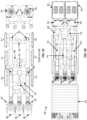
- FIG. 2 is a schematic diagram of a medium-low voltage power distribution system for the mobile fracturing system 103.
- the voltage and current levels referenced in FIG. 2 generally refer to AC electric power, other examples could have the mobile fracturing system 103 configured to be powered using DC electric power.
- the mobile source of electricity 102 provides power by connecting to the switch gear transport 112 using three medium voltage (e.g., 13.8 kV) cable connections.
- the mobile source of electricity 102 includes a turbine-electric generator transport that compresses and mixes combustion air with hydrocarbon gas to spin and generate mechanical energy and then converts the mechanical energy to electricity.
- the mobile source of electricity 102 could also include an inlet and exhaust transport that provides ventilation and combustion air to the turbine-electric generator transport when generating electricity. Configuring and utilizing a turbine-electric generator transport and an inlet and exhaust transport are discussed and shown in more detail in U.S. Patent 9,534,473, filed December 16, 2015 by Jeffrey G. Morris et al. and entitled "Mobile Electric Power Generation for Hydration Fracturing of Subsurface Geological Formations,".
- the mobile source of electricity 102 could include other transport configurations to employ a centralized source of electricity that powers fracturing equipment.
- the switch gear transport 112 contains a transformer that steps down the medium voltage (e.g., 13.8 kV) electric power to a low voltage level (e.g., 480 V) and provides a low voltage (e.g., 480 V) electrical connection to other transports.
- a low voltage level e.g., 480 V
- the switch gear transport 112 connects to the drive power transports 104 and the auxiliary unit transport 106 using the 480 V electrical connection.
- FIG. 2 also illustrates that the switch gear transport 112 utilizes four 480 V cable connections from an auxiliary power transport 120 that provides electric power to ignite, start, or power on the mobile source of electricity 102 and/or provide ancillary power where peak electric power demand exceeds the electric power output of mobile source of electricity 102.
- the switch gear transport 112 may also include a transformer to step down the electric power from a medium voltage level (e.g., 13.8 kV) to a relatively lower medium voltage level (e.g., 4.2 kV) and provide the relatively lower medium voltage level (e.g., 4.2 kV) directly to the drive power transports 104.
- a medium voltage level e.g. 13.8 kV
- a relatively lower medium voltage level e.g., 4.2 kV
- the relatively lower medium voltage level e.g., 4.2 kV
- both the hydration transport 118, blender transport 110, and fracturing pump transports 108 do not contain transformers to step down the voltage for the switch gear transport's 112 electric power. Instead, the voltages supplied to power the fracturing equipment (e.g., the electric prime movers) are stepped down upstream at different transports within the mobile fracturing system 103.
- the fracturing equipment e.g., the electric prime movers
- the drive power transports 104 may be operable to step down a medium voltage level (e.g., 13.8 kV) that the switch gear transport 112 supplies to a relatively lower medium voltage level (e.g., 4.2 kV), and the auxiliary unit transport 106 may be able to step down a medium voltage level (e.g., 13.8 kV) that the switch gear transport 112 supplies to a low voltage level (e.g., 480 V).
- switch gear transport 112 may include other transformers that step down the voltage to other voltages.
- the drive power transports 104 and auxiliary unit transport 106 then supply the stepped down voltages to power electric prime movers mounted on transports (e.g., blender transport 110 and fracturing pump transports 108) and other fracturing equipment.
- the transformers and/or drives (e.g., VFDs) for controlling the electric prime movers may be placed on drive power transports 104 and/or auxiliary unit transport 106 because the fracturing pump transports 108 and/or blender transports 110 may not have enough space or may exceed a specific weight limit.
- the switch gear transport 112 provides a medium voltage (e.g., 13.8 kV) electrical connection and a low voltage (e.g., 480 V) electrical connection to the drive power transports 104.
- each drive power transport 104 receives a single medium voltage (e.g., 13.8 kV) cable connection from the switch gear transport 112 and utilizes transformers to step down the voltage level of the received electric power from the medium voltage level (e.g., 13.8 kV) to a relatively lower medium voltage level (e.g., 4.2 kV).
- Each drive power transport 104 also receives a single low voltage (e.g., 480 V) cable connection from the switch gear transport 112.
- each drive power transport 104 After the drive power transports 104 receives electric power from the switch gear transport 112, each drive power transport 104 provides electric power to two different fracturing pump transports 108.
- the mobile fracturing system 103 implements a 2:1 ratio regarding the number of fracturing pump transports 108 that receive electric power from a drive power transport 104.
- Other examples could have different ratios where the drive power transport 104 supply power to a single fracturing pump transport 108 (e.g., 1:1 ratio) or more than two fracturing pump transport 108 (e.g., 3:1 or 4:1 ratio).
- each drive power transport 104 supplies a low voltage (e.g., 480 V) cable connection and two relatively lower medium voltage (e.g., 4.2 kV) cable connections to power each fracturing pump transport 108.
- the low voltage cable connection may supply electric power to drives (e.g., VFDs) and/or other electrical equipment (e.g., sensors) mounted on the fracturing pump transport 108.
- the two medium voltage (e.g., 4.2 kV) cable connections supply electric power to one or more electric prime movers that drive one or more pumps that pump fracturing fluid into a wellbore.
- the fracturing pump transport 108 contains a 5,000 horsepower (HP) dual-shaft electric motor that utilizes about 600 amperes (A) of electric current to operate.
- the dual-shaft electric motor could be a dual-shaft electric motor that is discussed and shown in more detail in U.S. Patent 9,534,473, filed December 16, 2015 by Jeffrey G. Morris et al. and entitled "Mobile Electric Power Generation for Hydration Fracturing of Subsurface Geological Formations.”
- each of the medium voltage (e.g., 4.2 kV) cable connections could provide about 300 A of electric current.
- Having a single medium voltage (e.g., 4.2 kV) electrical cable that provides 600 A of electric current to the dual-shaft electric motor may not be desirable because of safety concerns with the relatively high current flow. Besides safety concerns regarding the relatively high current (e.g., 600 A) flow, having a single electrical cable could also cause connection and/or disconnections issues because of the thicker cable size used to support relatively high current flow.
- a medium voltage (e.g., 4.2 kV) electrical cable that provides 600 A of electric current to the dual-shaft electric motor may not be desirable because of safety concerns with the relatively high current flow.
- having a single electrical cable could also cause connection and/or disconnections issues because of the thicker cable size used to support relatively high current flow.
- FIG. 2 also illustrates that the switch gear transport 112 supplies a single medium voltage (e.g., 13.8 kV) cable connection and a single low voltage (e.g., 480 V) cable connection to an auxiliary unit transport 106.
- the auxiliary unit transport 106 includes at least one transformer to step down the voltage from the medium voltage level (13.8 kV) to the low voltage level (e.g., 480 V).
- the auxiliary unit transport 106 supplies a low voltage level (e.g., 480 V) electrical connection to both the hydration transport 118 and blender transport 110.
- a low voltage level e.g., 480 V
- the hydration transport 118 and blender transport 110 are separate and independent from each other, where the hydration transport 118 receives two low voltage (e.g., 480 V) cable connections and the blender transport 110 receives eight low voltage (e.g., 480 V) cable connections from the auxiliary unit transport 106.
- the auxiliary unit transport 106 provide a low voltage (e.g., 480 V) electrical connection (e.g., ten cable connections) to a single hydration-blender unit transport for when the blender transport 110 and hydration transport 118 are integrated into a single transport.
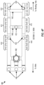
- FIG. 3 is a schematic diagram of an embodiment of a medium voltage power distribution system for the mobile fracturing system 302.
- the power distribution system moves the voltage step down further downstream by placing transformers 310 and/or 312 on the fracturing pump transports 304 and hydration-blender transport 306.
- the mobile fracturing system 302 reduces the number of transports by eliminating the need for an auxiliary unit transport (e.g., auxiliary unit transport 106 in FIG. 2 ) and/or drive power transports (e.g., drive power transports 104 in FIG. 2 ).
- the drives e.g., VFDs
- VFDs to control and monitor the electric prime movers of the fracturing pump transports 304 and transformers 310 and/or 312 for stepping down the voltage for the electric power are mounted on the fracturing pump transport 304 and the hydration-blender transport 306.
- FIG. 3 illustrates that switch gear transport 308 connects to a mobile source of electricity 102 with six medium voltage (e.g., 13.8 kV) cable connections.
- the switch gear transport also connects to an auxiliary power transport 120 with one medium voltage (e.g., 13.8 kV) cable connection.
- the switch gear transport 308 also includes a transformer 312 that steps down electric power received at a medium voltage level (e.g., 13.8 kV) from the auxiliary power transport 120 to a low voltage level (e.g., 480 V).
- the low voltage level (e.g., 480 V) connection may provide electric power to ignite, start, or power on the mobile source of electricity 102.
- a medium voltage level e.g., 13.8 kV
- the low voltage level (e.g., 480 V) connection may provide electric power to ignite, start, or power on the mobile source of electricity 102.
- FIG. 3 illustrates that switch gear transport 308 connects to a mobile source of electricity 102
- the switch gear transport 308 does not output or provide low voltage (e.g., 480 V) electrical connections to other transports. Specifically, the switch gear transport 308 outputs and supplies medium voltage (e.g., 13.8 kV) cable connections directly to the hydration-blender transport 306 and the fracturing pump transport 304 without connecting to any intermediate transports (e.g., drive power transport 104 and auxiliary unit transport 106 in FIG. 2 ).
- medium voltage e.g. 13.8 kV
- switch gear transport 308 generates a total seven medium voltage (e.g., 13.8 kV) cable connection, where each fracturing pump transports 304 is directly connected to the switch gear transport 308 with a single medium voltage (e.g., 13.8 kV) cable connection.
- the switch gear transport 308 also directly connects to the hydration-blender transport 306 using a single medium voltage (e.g., 13.8 kV) cable connection.
- the medium voltage power distribution system shown in FIG. 3 is able to reduce the number of electrical cables used to supply electric power to the fracturing pump transport 304 and hydration-blender transport 306 when compared to the medium-low power distribution system shown in FIG. 2 .
- the medium voltage power distribution system in FIG. 3 is able to reduce the number of electrical cables that provide power to each fracturing pump transport 304.
- the mobile fracturing system 302 reduces the number of electrical cables from three electrical cables to one electrical cable for each fracturing pump transport 304.
- a further reduction of electrical cables is shown by supplying one electrical cable to the hydration-blender transport 306 instead of the ten electrical cables used to power both the blender transport 110 and hydration transport 118.
- the medium voltage power distribution system is able to utilize less electrical cables is that each electrical cable does not need to supply a relatively high current (e.g., 600 A) to each of the fracturing pump transports 304 and hydration-blender transport 306.
- Supplying electric power at relatively lower current levels avoids the safety concerns and/or connection/disconnection issues associated with using a single electrical cable that supplies relatively high current (e.g., 600 A).
- Each fracturing pump transport 304 may include one or more transformers to step down the voltage received from the switch gear transport 308 to different voltage levels.
- each fracturing pump transport 304 may include two separate and independent transformers, a first transformer 310 to step down to a voltage level of 4.2 kV and a second transformer 312 to step down to a voltage level of 480 V.
- each fracturing pump transport 304 could include a single transformer that produces multiple voltages levels.
- the fracturing pump transport 304 may mount a three phase or three winding transformer to step down the voltage to two different voltage levels.
- Transformers 310 and 312 are configured to supply enough electric current to power the prime movers, drivers, and/or other control instrumentation.
- FIG. 3 also illustrates that the hydration-blender transport 306 may include a transformer that steps down the voltage level to 480 V.
- the hydration-blender transport 306 can use the stepped down voltages levels to provide electric power to the electric prime movers for the hydration-blender transport 306, drives, and/or other control instrumentation mounted on the hydration-blender transport 306.
- the hydration-blender transport 306 may also be configured to provide electric power at the 480 V voltage level to other downstream fracturing equipment, such as the sand conveyor.
- the medium voltage power distribution system may utilize two electrical connections to provide electric power to the sand conveyor.
- switch gear transport 308 provides electric power to a hydration-blender transport 306
- other embodiments could have the switch gear transport 308 separately connect to a hydration transport and a blender transport.
- the switch gear transport 308 may connect to the hydration transport using a single medium voltage (e.g., 13.8 kV) cable connection and another single medium voltage (e.g., 13.8 kV) cable connection to connect to the blender transport.
- a single medium voltage e.g., 13.8 kV
- another single medium voltage e.g., 13.8 kV
- the transports become individually autonomous by removing the need for other separate support-based trailers, such as the auxiliary unit transport and drive power transports that provide power conversion and/or drive control.
- Having autonomous trailers allows the mobile fracturing system 302 to become scalable and flexible, where each fracturing pump transport may be interchangeable with each other. For example, if the well is relatively small, the mobile fracturing system 302 may have a reduced number of fracturing pump transports 304 (e.g., four transports instead of six transports).
- more fracturing pump transports 304 can be stacked to increase pumping capacity without utilizing additional support-based transports (e.g., drive power transports 104 shown in FIGS. 1 and 2 ).
- the disclosure describes a switch gear transport 308 receiving electric power from a mobile source of electric.
- the switch gear transport 308 receive electric power from other types of power sources, such as a power grid or a stationary power source.
- the mobile fracturing system 302 shown in FIG. 3 may utilize a separate hydration transport and blender transport instead of the hydration-blender transport 306.
- FIG. 4A illustrates a side view of a hydration-blender transport 400 that comprises a hydration tank 402, a blender unit 404, an electric prime mover 406, a pump 408, and multiple manifold groups 410, 412, and 414.
- FIG. 4A also depicts that the hydration-blender transport 400 as a trailer that includes four axles.
- Other examples of the hydration-blender transport 400 may vary the number of axles depending on the weight of the fracturing equipment and/or the size of the hydration tank 402.
- the hydration-blender transport 400 may include three axles to allow for mounting of a hydration tank 402 with larger volume. By removing the axle 401 from the trailer, the hydration-blender transport 400 has more available space to mount a larger hydration tank 402.
- the manifold groups 410, 412, and 414 may be configured as inlet manifolds that receive source fluid and/or outlet manifolds that supply fracturing fluid to one or more fracturing pump transports.
- the manifold groups 410, 412, and 414 are coupled to the hydration-blender transport's 400 internal manifold system to route fluid within the hydration-blender transport 400.
- the electric prime movers 406 e.g., electric motors
- the internal manifold system includes a plurality of valves (not shown in FIG. 4A ) configured to isolate different sections of the internal manifold system.
- the internal manifold system may comprise a hydration tank manifold system 416, a hydration-blender manifold system 418, a blender output manifold system 420, an interconnector manifold system 424, and an under tank manifold system 430.
- the interconnector manifold system 424 may connect the manifold groups 410, 412, and 414, the pumps 408, the hydration tank manifold system 416, the hydration-blender manifold system 418, and the under tank manifold system 430 to each other.
- connection points 426 and 432 may be used to connect the interconnector manifold system 424 to the under tank manifold system 430.
- the hydration tank manifold system 416 may be configured to receive source fluid from one or more of the manifold groups 410, 412, and 414 via the interconnector manifold system 424 to transport the source fluid within the hydration tank 402.
- the hydration-blender manifold system 418 transports the hydrated fluid from the hydration tank 402 to blending tubs 454. Once the blending tubs 454 mix fracturing sand with the hydrated fluid to form fracturing fluid, the blender output manifold system 420 may then transport the fracturing fluid from the blender unit 404 to one or more manifold groups 410, 412, and 414.
- a feedback manifold system 428 may be configured to feedback liquid within the hydration tank 402 to maintain a desired level of hydrated fluid.
- the under tank manifold system 430 may be configured to connect the manifold groups 410, 412, and 414 to each other.
- the internal manifold system shown in FIG. 4 may include other components known by persons of ordinary skill in the art to monitor fluid properties and/or direct fluids within the hydration-blender transport 400, such as flow meters, densitometers, and valves.
- the hydration-blender transport 400 may include a power and control system 436.
- the power and control system 436 may include a drive (e.g., a VFD) to control the electric prime movers 406 and a transformer to step down incoming voltage.
- the transformer is configured to receive a relative higher voltage (e.g., 13.8 kV) and step down the voltage level to 480 V.
- the power and control system 436 may also be configured to provide electric power at the 480 V voltage level to other downstream fracturing equipment, such as the sand conveyor.
- the power and control system 436 may include the drive to control the electric prime movers 406, but may not include the transformer and instead receives power at the stepped down voltage (e.g., 480 V) from another transport.
- the blending tub 454 mixes the fracturing sand and hydrated fluid received from the hydration-blender manifold system 418 to produce the fracturing fluid that discharges via the blender output manifold system 420.
- the blending tub 454 may discharge the fracturing fluid using a pump (not shown in FIG. 4A ) driven by a prime mover.
- the metering component 452 is an auger positioned at an incline to meter the fracturing sand into a blending tub 454.
- Other examples of the blender unit 404 may have the metering component 452 positioned in a straight or horizontal orientation.
- Correctly controlling and metering fracturing sand into the blending tub 454 affects the overall proppant concentration of the fracturing fluid (e.g., weight of the slurry). Controlling the overall proppant concentration is advantageous because the overall proppant concentration could affect the proppant transport and the propped fracture dimensions of the subsurface geological formations and the realization of the hydraulic fracturing treatment.
- the crossing manifolds 440 and 442 allow fracturing fluid to be discharged to either side or both sides of the hydration-blender transport 400 and also allows the hydration tank to receive source fluid from either side of the hydration-blender transport 400.
- Each side of the under tank manifold system 430 also includes the manifold groups 410, 412, and 414, where each manifold group can be isolated using values (not shown in FIG. 4B ).
- the crossing manifolds 440 and 442 may include valves to allow or prevent fluid from flowing to both sides of the under tank manifold system 430.
- FIG. 4B also illustrates that the under tank manifold system 430 includes three pump connection points 446, connection points 426, and a connection point 432.
- the three pump connection points 446 interconnect the under tank manifold system 430 to the pumps 408 shown in FIG. 4A.
- FIG. 4A illustrates that the electric prime movers 406 are positioned above the pumps 408 such that one or more of the electric prime movers 406 may drive one or more pumps 408.
- the pumps 408 are then able to direct source fluid and/or fracturing fluid into and out of the under tank manifold system 430.
- the pumps 408 may be able to pump source fluid received from one or more manifold groups 410, 412, and 414 to the interconnector manifold system 424 via connection points 426.
- One or more valves can be set according to the operation mode for the hydration-blender transport 400.
- a valve associated with the connection point 432 may be set to an open position such that source fluid received from the manifold groups 410, 412, and 414 is sent directly to another manifold groups 410, 412, and 414 (e.g., manifold group 412) and bypasses the hydration tank 402.
- connection point 432 may be used to bypass the hydration tanks 402 and blending tubs 454 and directly pump source fluid received from one or more manifold groups 410, 412, and 414 back out to other manifold groups 410, 412, and 414.
- FIG. 4C illustrates a cross sectional view of the hydration-blender transport 400 that depicts the inside of the hydration tank 402.
- the inside of the hydration tank 402 includes the interconnector manifold system 424 that allows the pumps, driven by electric prime movers 406, to direct fluid to different sections of the internal manifold system.
- the interconnector manifold system 424 connects to the hydration tank manifold system 416 via connection points 462 and 438 and connects to the hydration-blender manifold system 418 via connection point 464.
- the pumps are able to direct source fluid received at one or more manifold groups 410, 412, and 414 to the hydration tank via the hydration tank manifold system 416 and/or pump hydrated fluid to the blending tubs 454 via the hydration-blender manifold system 418.
- FIG. 4D illustrates a top view of the hydration-blender transport 400 that depicts the top of the hydration tank 402.
- the hydration tank manifold system 416 receives source fluid and directs that source fluid to a diffuser located at the top of the hydration tank 402.
- the diffuser combines the source fluid with the polymer-based slurry and feeds the hydrated fluid to a tortuous flow path within the hydration tank 402.
- the hydration-blender manifold system 418 obtains the hydrated fluid via the interconnector manifold system 424 and supplies the hydrated fluid to the blending tubs 454.
- the hydration-blender manifold system 418 includes two different manifold connections, where each manifold connection supplies hydrated fluid to one of the blending tubs 454. Afterwards, the blending tub discharges the fracturing fluid via the blender output manifold system 420.
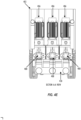
- FIG. 4E illustrates a cross sectional view of the hydration-blender transport 400 that corresponds to section cut A-A shown in FIG. 4D .
- the electric prime mover 406 and pump 408 combination is mounted in an upright position such that the electric prime mover 406 is mounted on top of the pump 408.
- the pumps 408 are also connected to the under tank manifold system 430. Three different electric prime mover 406 and pump 408 combinations may be used to provide enough power to simultaneously pump source fluid into the hydration-blender transport 400, pump hydrated fluid into the blending tubs 454, and/or pump fluid out of the hydration-blender transport 400.
- the pumps 408 may be centrifugal pumps.
- FIG. 4F illustrates an under tank cross sectional view of another example of a hydration-blender transport 400.
- FIG. 4F represents the C-C cross sectional view illustration of an under tank manifold system 480 that is substantially similar to the under tank manifold system 430 shown in FIG. 4B .
- the under tank manifold system 480 is similar to the under tank manifold system 430 except that the under tank manifold system 480 includes a sump 482 for collecting and remove fluid from the hydration tank 402.
- the operator may empty fluid stored within the hydration tank 402 before transportation.
- An operator is able to divert stored fluid within the hydration tank 402 to the sump 482 when discharging fluid out of the hydration tank 402.
- FIG. 5 illustrates an example of a hydration-blender transport 500 that includes a single blending tub.
- FIG. 5 illustrates a top view of the hydration-blender transport 500 that depicts the top of the hydration tank.
- FIG. 5 is similar to FIG. 4D except that manifolds within the hydration-blender manifold system 418 and blender output manifold system 420 that correspond to the missing blending tub have been removed.
- the hydration-blender manifold system 418 supplies the hydrated fluid to only one blending tub 454.
- the hydration-blender manifold system 418 includes only one manifold connection to supply hydrated fluid to the one blending tubs 454. Afterwards, the blending tub 454 discharges the fracturing fluid via the blender output manifold system 420(e.g., using a pump not shown in FIG. 5 ), which only has one outlet manifold connection to the blending tub 454.
- FIG. 5 illustrates that three electric prime movers 406 may be used to drive three pumps 408, other examples of the hydration-blender transport 500 could include two electric prime movers 406 that drive two pumps 408.
- FIG. 6 is a flow chart of an example of a method 600 to provide fracturing fluid using a single hydration-blender transport.
- Method 600 may correspond to the hydration-blender operation mode and the split-stream operation mode.
- the use and discussion of FIG. 6 is only an example to facilitate explanation and is not intended to limit the disclosure to this specific example.
- FIG. 6 illustrates that the blocks within method 600 are implemented in a sequential order, method 600 is not limited to this sequential order.
- one or more of the blocks, such as blocks 604 and 606, could be implemented in parallel.
- Method 600 may start at block 602 by receiving source fluid from one or more inlet/outlet manifolds. To implement block 602, method 600 may configure one or more values within the hydration-blender transport such that some of the inlet/outlet manifolds are configured to receive source fluid and some of the of inlet/outlet manifolds discharge fracturing fluid. Method 600 may then move to block 604 and drive one or more pumps to route the source fluid from the inlet/outlet manifolds into a hydration tank. In one example, method 600 may use electric prime movers to drive pumps to route the source fluid.
- Method 600 continues to block 606 and hydrates a polymer-based slurry with the source fluid to produce hydrated fluid with a target viscosity.
- method 600 may utilize a tortuous flow path that provides enough residence time and a flow rate to supply fracturing fluid to a blender unit. Afterwards, method 600 moves to block 608 and drives one or more pumps to route the hydrated fluid into one or more blending tubs. Method 600 then moves to block 610 and mixes the hydrated fluid with metered fracturing sand to produce fracturing fluid. Afterwards, method 600 continues to block 612 and drives one or more pumps to discharge the fracturing fluid from the blending tubs. Prior to discharging the fracturing fluid, method 600 may configure one or more valves to direct which inlet/outlet manifolds receive the fracturing fluid.
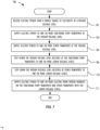
- FIG. 7 is a flow chart of an example of a method 700 to supply electric power to fracturing equipment using a medium voltage power distribution system.
- the medium voltage power distribution system that includes the switch gear transport 308 and transformers 310 and 312 shown in FIG. 3 can implement method 700.
- the use and discussion of FIG. 7 is only an example to facilitate explanation and is not intended to limit the disclosure to this specific example.
- FIG. 7 illustrates that the blocks within method 700 are implemented in a sequential order, method 700 is not limited to this sequential order.
- one or more of the blocks, such as blocks 704 and 706, could be implemented in parallel.
- Method 700 may start at block 702 by receiving electric power from a mobile source of electricity at a medium voltage level. As an example, method 700 receives electric power at 13.8 kV or at some other relatively higher medium voltage level from the mobile source of electricity. In one or more other examples, method 700 may receive electric power from other power sources, such as a power grid or a power plant. Method 700 may then move to block 704 and supply electric power to one or more fracturing pump transports at the medium voltage level (e.g., 13.8 kV). At block 704, method 700 does not step down the electric power received from the mobile source of electricity to a lower voltage level using transformers. Instead, method 700 at block 706 supplies electric power to one or more transports at the medium voltage level. As discussed with reference to FIG. 3 , method 700 is able to reduce the number of electrical cables used to supply electric power to transports, such as fracturing pump transport 304 and hydration-blender transport 306, when compared to the medium-low power distribution system shown in FIG. 2 .
- Method 700 continues to block 708 and steps down the medium voltage level received at the fracturing pump transports to one or more lower voltage levels.
- method 700 may step down the voltage level to a lower medium voltage level (e.g., 4.2 kV) or a low voltage level (e.g., 600 V or 480 V).
- a lower medium voltage level e.g., 4.2 kV
- a low voltage level e.g. 600 V or 480 V.
- method 700 can step down the voltage at a hydration transport, a blender transport, a hydration-blender transport, or combinations thereof. Stepping down the voltage at the different transports also reduces the number of transports by eliminating the auxiliary unit transport. Subsequently, method 700 may move to block 712 and supply electric power to one or more electric prime movers mounted on the fracturing pump transports and other transports with the lower voltage levels.
Landscapes
- Engineering & Computer Science (AREA)
- Life Sciences & Earth Sciences (AREA)
- Geology (AREA)
- Mining & Mineral Resources (AREA)
- General Life Sciences & Earth Sciences (AREA)
- Mechanical Engineering (AREA)
- Geochemistry & Mineralogy (AREA)
- Physics & Mathematics (AREA)
- Environmental & Geological Engineering (AREA)
- Fluid Mechanics (AREA)
- General Engineering & Computer Science (AREA)
- Chemical & Material Sciences (AREA)
- Power Engineering (AREA)
- Materials Engineering (AREA)
- Organic Chemistry (AREA)
- Chemical Kinetics & Catalysis (AREA)
- Other Liquid Machine Or Engine Such As Wave Power Use (AREA)
- Insulated Conductors (AREA)
- Electric Cable Arrangement Between Relatively Moving Parts (AREA)
- Cable Transmission Systems, Equalization Of Radio And Reduction Of Echo (AREA)
- Connection Of Motors, Electrical Generators, Mechanical Devices, And The Like (AREA)
- Ac-Ac Conversion (AREA)
- Testing Relating To Insulation (AREA)
- Optical Communication System (AREA)
Claims (13)
- Elektrisches Frakturierungssystem (302), umfassend:einen Schaltanlagentransport (308), der elektrisch mit einer Stromerzeugungsquelle (102) verbunden ist und konfiguriert ist, um Strom auf einem ersten Mittelspannungspegel aus der Stromerzeugungsquelle zu empfangen;ein erstes Stromkabel (6), das mit dem Schaltanlagentransport (308) verbunden ist und einen ersten Strom auf dem ersten Mittelspannungspegel aus dem Schaltanlagentransport (308) zuführt; undeinen Frakturierungspumpentransport (304), umfassend: mindestens einen ersten Transformator (310, 312), einen Antrieb, eine Pumpe und eine elektrische Antriebsmaschine, die jeweils an dem Frakturierungspumpentransport (304) angeordnet sind, wobei der Frakturierungspumpentransport (304) nur über das erste Stromkabel (6) mit dem Schaltanlagentransport (308) elektrisch verbunden ist, wobei der erste von dem Schaltanlagentransport (308) über das erste Stromkabel (6) zugeführte Strom an dem mindestens einen ersten Transformator (310, 312) empfangen wird; und wobei der mindestens eine erste Transformator (310, 312) mit der elektrischen Antriebsmaschine und dem Antrieb elektrisch verbunden ist,wobei der mindestens eine erste Transformator (310, 312) konfiguriert ist, um den auf dem ersten Mittelspannungspegel empfangenen Strom auf einen ersten niedrigeren Mittelspannungspegel abzusenken, der die elektrische Antriebsmaschine versorgt; undwobei der mindestens eine erste Transformator (310, 312) ferner konfiguriert ist, um den auf dem ersten Mittelspannungspegel empfangenen ersten Strom auf einen ersten Niederspannungspegel abzusenken, der niedriger ist als der erste niedrigere Mittelspannungspegel und der den Antrieb versorgt.
- System nach Anspruch 1, wobei der erste Mittelspannungspegel und der erste niedrigere Mittelspannungspegel in einen Bereich von 1000 Volt bis 35 Kilovolt fallen.
- System nach Anspruch 2, wobei der erste Mittelspannungspegel auf 13,8 kV eingestellt ist.
- System nach Anspruch 1, wobei der erste Niederspannungspegel in einen Bereich von 50 Volt bis 1000 Volt fällt.
- System nach Anspruch 1, wobei der Schaltanlagentransport (308) über ein zweites Stromkabel (1) elektrisch mit einer Hilfsstromquelle (120) verbunden ist, die einen zweiten Strom auf dem ersten Mittelspannungspegel bereitstellt, wobei der Strom der Hilfsquelle (120) an einem zweiten Transformator (312) an dem Schaltanlagentransport (308) empfangen wird, der konfiguriert ist, um den ersten Mittelspannungspegel auf einen zweiten Niederspannungspegel abzusenken.
- System nach Anspruch 5, wobei der zweite Niederspannungspegel eine Spannung zum Zünden, Starten oder Betreiben der Stromerzeugungsquelle (102) ist.
- System nach Anspruch 6, ferner umfassend:ein drittes Stromkabel (1), das mit dem Schaltanlagentransport (308) verbunden ist und einen dritten Strom auf dem ersten Mittelspannungspegel aus dem Schaltanlagentransport (308) zuführt; undeinen Mischer-Hydrierungs-Transport (306), der über das dritte Stromkabel (1) elektrisch mit dem Schaltanlagentransport (308) verbunden ist, ohne mit irgendwelchen Zwischentransporten verbunden zu sein, die zwischen dem Schaltanlagentransport (308) und dem Mischer-Hydrierungs-Transport (306) angeordnet sind;wobei der Mischer-Hydrierungs-Transport (306) optional ferner einen dritten Transformator umfasst, der den dritten Strom vom ersten Mittelspannungspegel auf den ersten Niederspannungspegel absenkt.
- System (302) nach Anspruch 1, wobei der mindestens eine erste Transformator (310, 312) eines der Folgenden umfasst:einen einzelnen Transformator (310, 312), der konfiguriert ist, um den ersten Mittelspannungspegel auf den ersten niedrigeren Mittelspannungspegel und den ersten Niederspannungspegel abzusenken; undeinen Transformator (310), der konfiguriert ist, um den ersten Mittelspannungspegel auf den ersten niedrigeren Mittelspannungspegel abzusenken, und einen anderen Transformator (312), der konfiguriert ist, um den ersten Mittelspannungspegel auf den ersten Niederspannungspegel abzusenken.
- Verfahren zur Verteilung von Strom für Frakturierungsgvorgänge, wobei das Verfahren Folgendes umfasst:Empfangen eines ersten Stroms aus einer Stromerzeugungsquelle (102) auf einem ersten Mittelspannungspegel an einem Schaltanlagentransport (308);Zuführen des ersten Stroms auf dem ersten Mittelspannungspegel aus dem Schaltanlagentransport (308) unter Verwendung nur einer ersten Kabelverbindung (6);Empfangen des ersten Stroms auf dem ersten Mittelspannungspegel, der direkt unter Verwendung der ersten Kabelverbindung (6) zugeführt wird, an einem Frakturierungspumpentransport (304);Absenken des ersten Mittelspannungspegels mit mindestens einem an dem Frakturierungspumpentransport (304) angeordneten ersten Transformator (310, 312) sowohl auf einen niedrigeren Mittelspannungspegel als auch auf einen Niederspannungspegel;Betreiben einer an dem Frakturierungspumpentransport (304) angeordneten elektrischen Antriebsmaschine mit dem unteren Mittelspannungspegel;Betreiben eines an dem Frakturierungspumpentransport (304) angeordneten Antriebs mit dem Niederspannungspegel; undSteuern der Ausgabe der betriebenen elektrischen Antriebsmaschine mit dem betriebenen Antrieb.
- Verfahren nach Anspruch 9, ferner umfassend:Zuführen eines zweiten Stroms auf dem ersten Mittelspannungspegel aus dem Schaltanlagentransport (308) unter Verwendung nur einer zweiten Kabelverbindung (1); undEmpfangen des unter Verwendung der zweiten Kabelverbindung (1) direkt zugeführten zweiten Stroms auf dem ersten Mittelspannungspegel an einem Mischer-Transport (306), einem Hydrierungs-Transport (306) und/oder einem Mischer-Hydrierungs-Transport (306).
- Verfahren nach Anspruch 9, wobei der erste Mittelspannungspegel und der niedrigere Mittelspannungspegel in einen Bereich von 1000 Volt bis 35 Kilovolt fallen.
- Verfahren nach Anspruch 9, wobei der Niederspannungspegel in einen Bereich von 50 Volt bis 1000 Volt fällt.
- Verfahren nach Anspruch 9, ferner umfassend das Empfangen von Strom auf dem ersten Mittelspannungspegel aus einem Hilfsstromtransport (120) am Schaltanlagentransport (308);Absenken des Stroms aus dem Hilfsstromtransport (120) vom ersten Mittelspannungspegel auf den Niederspannungspegel mit einem am Schaltanlagentransport (308) angeordneten zweiten Transformator (312); undZuführen des Stroms auf dem Niederspannungspegel aus dem Schaltanlagentransport (308) an die Stromerzeugungsquelle, um die Stromerzeugungsquelle (102) zu zünden und zu starten.
Priority Applications (1)
| Application Number | Priority Date | Filing Date | Title |
|---|---|---|---|
| EP25166917.2A EP4554064A3 (de) | 2017-06-29 | 2018-06-28 | Elektrische stromverteilung für frakturierungsbetrieb |
Applications Claiming Priority (2)
| Application Number | Priority Date | Filing Date | Title |
|---|---|---|---|
| US201762526869P | 2017-06-29 | 2017-06-29 | |
| PCT/US2018/039982 WO2019006108A1 (en) | 2017-06-29 | 2018-06-28 | ELECTRICAL POWER DISTRIBUTION FOR FRACTURING OPERATION |
Related Child Applications (1)
| Application Number | Title | Priority Date | Filing Date |
|---|---|---|---|
| EP25166917.2A Division EP4554064A3 (de) | 2017-06-29 | 2018-06-28 | Elektrische stromverteilung für frakturierungsbetrieb |
Publications (3)
| Publication Number | Publication Date |
|---|---|
| EP3645832A1 EP3645832A1 (de) | 2020-05-06 |
| EP3645832A4 EP3645832A4 (de) | 2021-06-09 |
| EP3645832B1 true EP3645832B1 (de) | 2025-04-02 |
Family
ID=64737887
Family Applications (3)
| Application Number | Title | Priority Date | Filing Date |
|---|---|---|---|
| EP18822709.4A Withdrawn EP3645833A4 (de) | 2017-06-29 | 2018-06-28 | Hydratationsmischertransport für den frakturierungsbetrieb |
| EP25166917.2A Pending EP4554064A3 (de) | 2017-06-29 | 2018-06-28 | Elektrische stromverteilung für frakturierungsbetrieb |
| EP18825305.8A Active EP3645832B1 (de) | 2017-06-29 | 2018-06-28 | Elektrische stromverteilung für frakturierungsbetrieb |
Family Applications Before (2)
| Application Number | Title | Priority Date | Filing Date |
|---|---|---|---|
| EP18822709.4A Withdrawn EP3645833A4 (de) | 2017-06-29 | 2018-06-28 | Hydratationsmischertransport für den frakturierungsbetrieb |
| EP25166917.2A Pending EP4554064A3 (de) | 2017-06-29 | 2018-06-28 | Elektrische stromverteilung für frakturierungsbetrieb |
Country Status (10)
| Country | Link |
|---|---|
| US (4) | US10415332B2 (de) |
| EP (3) | EP3645833A4 (de) |
| AR (3) | AR112485A1 (de) |
| BR (2) | BR112019028085B1 (de) |
| CA (3) | CA3123640C (de) |
| ES (1) | ES3021412T3 (de) |
| HU (1) | HUE072015T2 (de) |
| MX (2) | MX2019015581A (de) |
| PL (1) | PL3645832T3 (de) |
| WO (2) | WO2019006106A1 (de) |
Families Citing this family (114)
| Publication number | Priority date | Publication date | Assignee | Title |
|---|---|---|---|---|
| US11255173B2 (en) | 2011-04-07 | 2022-02-22 | Typhon Technology Solutions, Llc | Mobile, modular, electrically powered system for use in fracturing underground formations using liquid petroleum gas |
| US9140110B2 (en) | 2012-10-05 | 2015-09-22 | Evolution Well Services, Llc | Mobile, modular, electrically powered system for use in fracturing underground formations using liquid petroleum gas |
| US11708752B2 (en) | 2011-04-07 | 2023-07-25 | Typhon Technology Solutions (U.S.), Llc | Multiple generator mobile electric powered fracturing system |
| US9995218B2 (en) | 2012-11-16 | 2018-06-12 | U.S. Well Services, LLC | Turbine chilling for oil field power generation |
| US9970278B2 (en) | 2012-11-16 | 2018-05-15 | U.S. Well Services, LLC | System for centralized monitoring and control of electric powered hydraulic fracturing fleet |
| US10232332B2 (en) | 2012-11-16 | 2019-03-19 | U.S. Well Services, Inc. | Independent control of auger and hopper assembly in electric blender system |
| US9745840B2 (en) | 2012-11-16 | 2017-08-29 | Us Well Services Llc | Electric powered pump down |
| US9650879B2 (en) | 2012-11-16 | 2017-05-16 | Us Well Services Llc | Torsional coupling for electric hydraulic fracturing fluid pumps |
| US9893500B2 (en) | 2012-11-16 | 2018-02-13 | U.S. Well Services, LLC | Switchgear load sharing for oil field equipment |
| US10020711B2 (en) | 2012-11-16 | 2018-07-10 | U.S. Well Services, LLC | System for fueling electric powered hydraulic fracturing equipment with multiple fuel sources |
| US9410410B2 (en) | 2012-11-16 | 2016-08-09 | Us Well Services Llc | System for pumping hydraulic fracturing fluid using electric pumps |
| US10407990B2 (en) | 2012-11-16 | 2019-09-10 | U.S. Well Services, LLC | Slide out pump stand for hydraulic fracturing equipment |
| US10036238B2 (en) | 2012-11-16 | 2018-07-31 | U.S. Well Services, LLC | Cable management of electric powered hydraulic fracturing pump unit |
| US10526882B2 (en) | 2012-11-16 | 2020-01-07 | U.S. Well Services, LLC | Modular remote power generation and transmission for hydraulic fracturing system |
| US11476781B2 (en) | 2012-11-16 | 2022-10-18 | U.S. Well Services, LLC | Wireline power supply during electric powered fracturing operations |
| US10254732B2 (en) | 2012-11-16 | 2019-04-09 | U.S. Well Services, Inc. | Monitoring and control of proppant storage from a datavan |
| US11959371B2 (en) | 2012-11-16 | 2024-04-16 | Us Well Services, Llc | Suction and discharge lines for a dual hydraulic fracturing unit |
| US11449018B2 (en) | 2012-11-16 | 2022-09-20 | U.S. Well Services, LLC | System and method for parallel power and blackout protection for electric powered hydraulic fracturing |
| US10119381B2 (en) | 2012-11-16 | 2018-11-06 | U.S. Well Services, LLC | System for reducing vibrations in a pressure pumping fleet |
| CA2908276C (en) | 2014-10-14 | 2022-11-01 | Us Well Services Llc | Parallel power and blackout protection for electric hydraulic fracturing |
| MX383620B (es) | 2014-12-19 | 2025-03-14 | Typhon Tech Solutions Llc | Generacion de energia electrica movil para la fracturacion hidraulica de formaciones geologicas de subsuperficie. |
| US12078110B2 (en) | 2015-11-20 | 2024-09-03 | Us Well Services, Llc | System for gas compression on electric hydraulic fracturing fleets |
| US12027831B2 (en) | 2016-04-15 | 2024-07-02 | U.S. Well Services, LLC | Switchgear load sharing for oil field equipment |
| WO2018074995A1 (en) * | 2016-10-17 | 2018-04-26 | Halliburton Energy Services, Inc. | Improved distribution unit |
| US11181107B2 (en) | 2016-12-02 | 2021-11-23 | U.S. Well Services, LLC | Constant voltage power distribution system for use with an electric hydraulic fracturing system |
| US12442338B2 (en) * | 2017-01-25 | 2025-10-14 | Electronic Power Design, Inc. | Mobile electric fracking trailer power supply system |
| US11624326B2 (en) | 2017-05-21 | 2023-04-11 | Bj Energy Solutions, Llc | Methods and systems for supplying fuel to gas turbine engines |
| CA3123640C (en) | 2017-06-29 | 2023-08-29 | Jeffrey G. Morris | Hydration-blender transport for fracturing operation |
| US10280724B2 (en) | 2017-07-07 | 2019-05-07 | U.S. Well Services, Inc. | Hydraulic fracturing equipment with non-hydraulic power |
| CA3078509A1 (en) | 2017-10-05 | 2019-04-11 | U.S. Well Services, LLC | Instrumented fracturing slurry flow system and method |
| WO2019075475A1 (en) | 2017-10-13 | 2019-04-18 | U.S. Well Services, LLC | AUTOMATIC FRACTURING SYSTEM AND METHOD |
| AR114805A1 (es) | 2017-10-25 | 2020-10-21 | U S Well Services Llc | Método y sistema de fracturación inteligente |
| WO2019113153A1 (en) | 2017-12-05 | 2019-06-13 | U.S. Well Services, Inc. | High horsepower pumping configuration for an electric hydraulic fracturing system |
| CA3084596A1 (en) | 2017-12-05 | 2019-06-13 | U.S. Well Services, LLC | Multi-plunger pumps and associated drive systems |
| WO2019152981A1 (en) * | 2018-02-05 | 2019-08-08 | U.S. Well Services, Inc. | Microgrid electrical load management |
| CA3097051A1 (en) | 2018-04-16 | 2019-10-24 | U.S. Well Services, LLC | Hybrid hydraulic fracturing fleet |
| US11211801B2 (en) | 2018-06-15 | 2021-12-28 | U.S. Well Services, LLC | Integrated mobile power unit for hydraulic fracturing |
| CA3107917C (en) * | 2018-08-01 | 2024-01-23 | Typhon Technology Solutions, Llc | Switch gear transport that distributes power for fracturing operations |
| US10648270B2 (en) | 2018-09-14 | 2020-05-12 | U.S. Well Services, LLC | Riser assist for wellsites |
| WO2020076902A1 (en) * | 2018-10-09 | 2020-04-16 | U.S. Well Services, LLC | Modular switchgear system and power distribution for electric oilfield equipment |
| US10914155B2 (en) | 2018-10-09 | 2021-02-09 | U.S. Well Services, LLC | Electric powered hydraulic fracturing pump system with single electric powered multi-plunger pump fracturing trailers, filtration units, and slide out platform |
| US10738580B1 (en) | 2019-02-14 | 2020-08-11 | Service Alliance—Houston LLC | Electric driven hydraulic fracking system |
| CA3072788C (en) | 2019-02-14 | 2024-02-27 | National Service Alliance - Houston Llc | Parameter monitoring and control for an electric driven hydraulic fracking system |
| CA3072660C (en) | 2019-02-14 | 2020-12-08 | National Service Alliance - Houston Llc | Electric driven hydraulic fracking operation |
| US10794165B2 (en) | 2019-02-14 | 2020-10-06 | National Service Alliance—Houston LLC | Power distribution trailer for an electric driven hydraulic fracking system |
| US10753153B1 (en) | 2019-02-14 | 2020-08-25 | National Service Alliance—Houston LLC | Variable frequency drive configuration for electric driven hydraulic fracking system |
| US11578577B2 (en) | 2019-03-20 | 2023-02-14 | U.S. Well Services, LLC | Oversized switchgear trailer for electric hydraulic fracturing |
| WO2020231483A1 (en) | 2019-05-13 | 2020-11-19 | U.S. Well Services, LLC | Encoderless vector control for vfd in hydraulic fracturing applications |
| US11560845B2 (en) | 2019-05-15 | 2023-01-24 | Bj Energy Solutions, Llc | Mobile gas turbine inlet air conditioning system and associated methods |
| WO2020251978A1 (en) | 2019-06-10 | 2020-12-17 | U.S. Well Services, LLC | Integrated fuel gas heater for mobile fuel conditioning equipment |
| CA3143799A1 (en) * | 2019-07-01 | 2021-01-07 | National Oilwell Varco, L.P. | Close coupled fluid processing system |
| US11542786B2 (en) | 2019-08-01 | 2023-01-03 | U.S. Well Services, LLC | High capacity power storage system for electric hydraulic fracturing |
| US11108234B2 (en) | 2019-08-27 | 2021-08-31 | Halliburton Energy Services, Inc. | Grid power for hydrocarbon service applications |
| CA3092829C (en) | 2019-09-13 | 2023-08-15 | Bj Energy Solutions, Llc | Methods and systems for supplying fuel to gas turbine engines |
| CA3092863C (en) | 2019-09-13 | 2023-07-18 | Bj Energy Solutions, Llc | Fuel, communications, and power connection systems and related methods |
| US12338772B2 (en) | 2019-09-13 | 2025-06-24 | Bj Energy Solutions, Llc | Systems, assemblies, and methods to enhance intake air flow to a gas turbine engine of a hydraulic fracturing unit |
| US11002189B2 (en) | 2019-09-13 | 2021-05-11 | Bj Energy Solutions, Llc | Mobile gas turbine inlet air conditioning system and associated methods |
| US12065968B2 (en) | 2019-09-13 | 2024-08-20 | BJ Energy Solutions, Inc. | Systems and methods for hydraulic fracturing |
| CA3092865C (en) | 2019-09-13 | 2023-07-04 | Bj Energy Solutions, Llc | Power sources and transmission networks for auxiliary equipment onboard hydraulic fracturing units and associated methods |
| US11015594B2 (en) | 2019-09-13 | 2021-05-25 | Bj Energy Solutions, Llc | Systems and method for use of single mass flywheel alongside torsional vibration damper assembly for single acting reciprocating pump |
| US10815764B1 (en) | 2019-09-13 | 2020-10-27 | Bj Energy Solutions, Llc | Methods and systems for operating a fleet of pumps |
| US10895202B1 (en) | 2019-09-13 | 2021-01-19 | Bj Energy Solutions, Llc | Direct drive unit removal system and associated methods |
| US10989180B2 (en) | 2019-09-13 | 2021-04-27 | Bj Energy Solutions, Llc | Power sources and transmission networks for auxiliary equipment onboard hydraulic fracturing units and associated methods |
| CA3092868A1 (en) | 2019-09-13 | 2021-03-13 | Bj Energy Solutions, Llc | Turbine engine exhaust duct system and methods for noise dampening and attenuation |
| US11015536B2 (en) | 2019-09-13 | 2021-05-25 | Bj Energy Solutions, Llc | Methods and systems for supplying fuel to gas turbine engines |
| US11604113B2 (en) | 2019-09-13 | 2023-03-14 | Bj Energy Solutions, Llc | Fuel, communications, and power connection systems and related methods |
| CA3197583A1 (en) | 2019-09-13 | 2021-03-13 | Bj Energy Solutions, Llc | Fuel, communications, and power connection systems and related methods |
| US11459863B2 (en) | 2019-10-03 | 2022-10-04 | U.S. Well Services, LLC | Electric powered hydraulic fracturing pump system with single electric powered multi-plunger fracturing pump |
| US12012952B2 (en) | 2019-11-18 | 2024-06-18 | U.S. Well Services, LLC | Electrically actuated valves for manifold trailers or skids |
| WO2021108985A1 (zh) * | 2019-12-03 | 2021-06-10 | 烟台杰瑞石油装备技术有限公司 | 一种压裂的井场布局系统 |
| WO2021134063A1 (en) | 2019-12-27 | 2021-07-01 | U.S. Well Services, LLC | Systems and methods for fluid end health monitoring |
| US11009162B1 (en) | 2019-12-27 | 2021-05-18 | U.S. Well Services, LLC | System and method for integrated flow supply line |
| US11846167B2 (en) | 2019-12-30 | 2023-12-19 | U.S. Well Services, LLC | Blender tub overflow catch |
| US11885206B2 (en) | 2019-12-30 | 2024-01-30 | U.S. Well Services, LLC | Electric motor driven transportation mechanisms for fracturing blenders |
| US11960305B2 (en) | 2019-12-31 | 2024-04-16 | U.S. Well Services, LLC | Automated blender bucket testing and calibration |
| US11492886B2 (en) | 2019-12-31 | 2022-11-08 | U.S. Wells Services, LLC | Self-regulating FRAC pump suction stabilizer/dampener |
| US11560887B2 (en) | 2019-12-31 | 2023-01-24 | U.S. Well Services, LLC | Segmented fluid end plunger pump |
| CN111456697B (zh) * | 2020-04-07 | 2022-05-03 | 四川宏华石油设备有限公司 | 一种电动混配设备 |
| US11708829B2 (en) | 2020-05-12 | 2023-07-25 | Bj Energy Solutions, Llc | Cover for fluid systems and related methods |
| US10968837B1 (en) | 2020-05-14 | 2021-04-06 | Bj Energy Solutions, Llc | Systems and methods utilizing turbine compressor discharge for hydrostatic manifold purge |
| US11428165B2 (en) | 2020-05-15 | 2022-08-30 | Bj Energy Solutions, Llc | Onboard heater of auxiliary systems using exhaust gases and associated methods |
| US11208880B2 (en) | 2020-05-28 | 2021-12-28 | Bj Energy Solutions, Llc | Bi-fuel reciprocating engine to power direct drive turbine fracturing pumps onboard auxiliary systems and related methods |
| US11109508B1 (en) | 2020-06-05 | 2021-08-31 | Bj Energy Solutions, Llc | Enclosure assembly for enhanced cooling of direct drive unit and related methods |
| US11208953B1 (en) | 2020-06-05 | 2021-12-28 | Bj Energy Solutions, Llc | Systems and methods to enhance intake air flow to a gas turbine engine of a hydraulic fracturing unit |
| US10961908B1 (en) | 2020-06-05 | 2021-03-30 | Bj Energy Solutions, Llc | Systems and methods to enhance intake air flow to a gas turbine engine of a hydraulic fracturing unit |
| US11022526B1 (en) | 2020-06-09 | 2021-06-01 | Bj Energy Solutions, Llc | Systems and methods for monitoring a condition of a fracturing component section of a hydraulic fracturing unit |
| US10954770B1 (en) | 2020-06-09 | 2021-03-23 | Bj Energy Solutions, Llc | Systems and methods for exchanging fracturing components of a hydraulic fracturing unit |
| US11066915B1 (en) | 2020-06-09 | 2021-07-20 | Bj Energy Solutions, Llc | Methods for detection and mitigation of well screen out |
| US11111768B1 (en) | 2020-06-09 | 2021-09-07 | Bj Energy Solutions, Llc | Drive equipment and methods for mobile fracturing transportation platforms |
| US11125066B1 (en) | 2020-06-22 | 2021-09-21 | Bj Energy Solutions, Llc | Systems and methods to operate a dual-shaft gas turbine engine for hydraulic fracturing |
| US11939853B2 (en) | 2020-06-22 | 2024-03-26 | Bj Energy Solutions, Llc | Systems and methods providing a configurable staged rate increase function to operate hydraulic fracturing units |
| US11028677B1 (en) | 2020-06-22 | 2021-06-08 | Bj Energy Solutions, Llc | Stage profiles for operations of hydraulic systems and associated methods |
| US11933153B2 (en) | 2020-06-22 | 2024-03-19 | Bj Energy Solutions, Llc | Systems and methods to operate hydraulic fracturing units using automatic flow rate and/or pressure control |
| US11473413B2 (en) | 2020-06-23 | 2022-10-18 | Bj Energy Solutions, Llc | Systems and methods to autonomously operate hydraulic fracturing units |
| US11466680B2 (en) | 2020-06-23 | 2022-10-11 | Bj Energy Solutions, Llc | Systems and methods of utilization of a hydraulic fracturing unit profile to operate hydraulic fracturing units |
| US11149533B1 (en) | 2020-06-24 | 2021-10-19 | Bj Energy Solutions, Llc | Systems to monitor, detect, and/or intervene relative to cavitation and pulsation events during a hydraulic fracturing operation |
| US11220895B1 (en) | 2020-06-24 | 2022-01-11 | Bj Energy Solutions, Llc | Automated diagnostics of electronic instrumentation in a system for fracturing a well and associated methods |
| US11193361B1 (en) | 2020-07-17 | 2021-12-07 | Bj Energy Solutions, Llc | Methods, systems, and devices to enhance fracturing fluid delivery to subsurface formations during high-pressure fracturing operations |
| EP4186132A4 (de) | 2020-07-24 | 2024-10-16 | Voltagrid LLC | Common-bus-schaltanlage für mobile hybride mikronetze |
| US12500423B2 (en) | 2020-07-24 | 2025-12-16 | Voltagrid Llc | Mobile hybrid microgrid |
| CN112691570A (zh) * | 2020-12-31 | 2021-04-23 | 重庆市能源投资集团科技有限责任公司 | 一种用于煤矿井下压裂的加砂混合单元 |
| US11557940B2 (en) | 2021-02-08 | 2023-01-17 | Halliburton Energy Services, Inc. | Oilfield equipment configurable to receive power modules to utilize primary and secondary energy sources |
| CN112864817B (zh) | 2021-03-10 | 2025-06-06 | 烟台杰瑞石油装备技术有限公司 | 配电装置、配电拖车、电驱系统和电驱系统的操作方法 |
| US11639654B2 (en) | 2021-05-24 | 2023-05-02 | Bj Energy Solutions, Llc | Hydraulic fracturing pumps to enhance flow of fracturing fluid into wellheads and related methods |
| US11591888B2 (en) | 2021-06-18 | 2023-02-28 | Bj Energy Solutions, Llc | Hydraulic fracturing blender system |
| CN113404478A (zh) * | 2021-08-19 | 2021-09-17 | 四川宏华电气有限责任公司 | 一种页岩气全电动自动化压裂作业设备及方法 |
| CA3180024A1 (en) | 2021-10-25 | 2023-04-25 | Bj Energy Solutions, Llc | Systems and methods to reduce acoustic resonance or disrupt standing wave formation in a fluid manifold of a high-pressure fracturing system |
| US11725582B1 (en) * | 2022-04-28 | 2023-08-15 | Typhon Technology Solutions (U.S.), Llc | Mobile electric power generation system |
| US11913317B2 (en) | 2022-05-05 | 2024-02-27 | Colton Willis | Proppants processing system and method |
| US11955782B1 (en) * | 2022-11-01 | 2024-04-09 | Typhon Technology Solutions (U.S.), Llc | System and method for fracturing of underground formations using electric grid power |
| US12105481B1 (en) | 2023-03-15 | 2024-10-01 | Horizontal Wireline Services, Llc | System and method for automatic depth positioning of wire conveyed operations |
| US12186720B2 (en) | 2023-04-05 | 2025-01-07 | Texas Integrity Acid Solutions, Llc | Systems and methods for acid mixing |
| US12196067B1 (en) | 2023-06-16 | 2025-01-14 | Bj Energy Solutions, Llc | Hydraulic fracturing arrangement and blending system |
| US12577866B2 (en) | 2024-08-28 | 2026-03-17 | Spm Oil & Gas Inc. | Piping assembly for hydraulic fracturing manifold |
Family Cites Families (44)
| Publication number | Priority date | Publication date | Assignee | Title |
|---|---|---|---|---|
| US5512811A (en) | 1994-01-21 | 1996-04-30 | Sundstrand Corporation | Starter/generator system having multivoltage generation capability |
| US6193402B1 (en) * | 1998-03-06 | 2001-02-27 | Kristian E. Grimland | Multiple tub mobile blender |
| AU2003219848A1 (en) * | 2002-02-22 | 2003-09-09 | Flotek Indutries, Inc. | Mobile blending apparatus |
| US20040008571A1 (en) * | 2002-07-11 | 2004-01-15 | Coody Richard L. | Apparatus and method for accelerating hydration of particulate polymer |
| US7221061B2 (en) | 2002-12-02 | 2007-05-22 | Caterpillar Inc | Power generation system having an external process module |
| US20070132243A1 (en) | 2004-03-05 | 2007-06-14 | Engine & Energy Technology Corporation | Auxiliary power unit for a diesel powered transport vehicle |
| SE531694C2 (sv) * | 2007-12-19 | 2009-07-07 | Oehlins Racing Ab | Stötdämpare med dubbelkolv |
| CA2634861C (en) | 2008-06-11 | 2011-01-04 | Hitman Holdings Ltd. | Combined three-in-one fracturing system |
| US8828413B2 (en) * | 2009-02-24 | 2014-09-09 | New York University | Peptoid oligomers, pharmaceutical compositions and methods of using the same |
| US8698437B2 (en) * | 2009-05-15 | 2014-04-15 | Siemens Industry, Inc. | System and method for providing auxiliary power by regeneration power management in mobile mining equipment |
| ES2692897T3 (es) | 2011-04-07 | 2018-12-05 | Evolution Well Services, Llc | Sistema energizado eléctricamente, modular, móvil para uso en formaciones subterráneas de fracturación |
| US9140110B2 (en) * | 2012-10-05 | 2015-09-22 | Evolution Well Services, Llc | Mobile, modular, electrically powered system for use in fracturing underground formations using liquid petroleum gas |
| US8882336B1 (en) | 2011-08-26 | 2014-11-11 | McClinton Energy Group, LLC | Hydro-blender |
| US8899823B2 (en) | 2011-12-09 | 2014-12-02 | Advanced Stimulation Technology, Inc. | Gel hydration unit |
| AR087298A1 (es) | 2012-04-06 | 2014-03-12 | Evolution Well Services | Sistema movil, modular, alimentado electricamente para utilizar en la fractura de formaciones subterraneas |
| US20130306322A1 (en) * | 2012-05-21 | 2013-11-21 | General Electric Company | System and process for extracting oil and gas by hydraulic fracturing |
| US10407990B2 (en) * | 2012-11-16 | 2019-09-10 | U.S. Well Services, LLC | Slide out pump stand for hydraulic fracturing equipment |
| US11476781B2 (en) | 2012-11-16 | 2022-10-18 | U.S. Well Services, LLC | Wireline power supply during electric powered fracturing operations |
| US9410410B2 (en) * | 2012-11-16 | 2016-08-09 | Us Well Services Llc | System for pumping hydraulic fracturing fluid using electric pumps |
| US11449018B2 (en) * | 2012-11-16 | 2022-09-20 | U.S. Well Services, LLC | System and method for parallel power and blackout protection for electric powered hydraulic fracturing |
| US9893500B2 (en) | 2012-11-16 | 2018-02-13 | U.S. Well Services, LLC | Switchgear load sharing for oil field equipment |
| US10020711B2 (en) * | 2012-11-16 | 2018-07-10 | U.S. Well Services, LLC | System for fueling electric powered hydraulic fracturing equipment with multiple fuel sources |
| US9745840B2 (en) * | 2012-11-16 | 2017-08-29 | Us Well Services Llc | Electric powered pump down |
| US10232332B2 (en) | 2012-11-16 | 2019-03-19 | U.S. Well Services, Inc. | Independent control of auger and hopper assembly in electric blender system |
| US9995218B2 (en) | 2012-11-16 | 2018-06-12 | U.S. Well Services, LLC | Turbine chilling for oil field power generation |
| US10036238B2 (en) * | 2012-11-16 | 2018-07-31 | U.S. Well Services, LLC | Cable management of electric powered hydraulic fracturing pump unit |
| US20140238683A1 (en) * | 2013-02-27 | 2014-08-28 | Nabors Alaska Drilling, Inc. | Integrated Arctic Fracking Apparatus and Methods |
| US9322397B2 (en) * | 2013-03-06 | 2016-04-26 | Baker Hughes Incorporated | Fracturing pump assembly and method thereof |
| US20150114652A1 (en) | 2013-03-07 | 2015-04-30 | Prostim Labs, Llc | Fracturing systems and methods for a wellbore |
| US9452394B2 (en) * | 2013-06-06 | 2016-09-27 | Baker Hughes Incorporated | Viscous fluid dilution system and method thereof |
| MX383620B (es) * | 2014-12-19 | 2025-03-14 | Typhon Tech Solutions Llc | Generacion de energia electrica movil para la fracturacion hidraulica de formaciones geologicas de subsuperficie. |
| US10378326B2 (en) * | 2014-12-19 | 2019-08-13 | Typhon Technology Solutions, Llc | Mobile fracturing pump transport for hydraulic fracturing of subsurface geological formations |
| US9587649B2 (en) * | 2015-01-14 | 2017-03-07 | Us Well Services Llc | System for reducing noise in a hydraulic fracturing fleet |
| CA3200448C (en) * | 2015-03-04 | 2024-02-27 | Stewart & Stevenson Llc | Well fracturing systems with electrical motors and methods of use |
| US10076733B2 (en) | 2016-03-08 | 2018-09-18 | Evolution Well Services, Llc | Utilizing wet fracturing sand for hydraulic fracturing operations |
| US10855142B2 (en) | 2016-04-19 | 2020-12-01 | Supreme Electrical Services, Inc. | Power system for well service pumps |
| EP3264088A1 (de) | 2016-07-02 | 2018-01-03 | Universite De Liege | Verfahren zur frühdiagnose von immunvermittelter entzündungskrankheit |
| CA3040459C (en) | 2016-10-14 | 2021-02-16 | Dresser-Rand Company | Hydraulic fracturing system |
| US11181107B2 (en) | 2016-12-02 | 2021-11-23 | U.S. Well Services, LLC | Constant voltage power distribution system for use with an electric hydraulic fracturing system |
| US10953936B2 (en) * | 2016-12-09 | 2021-03-23 | David W. Lutz | Double stretch trailer |
| US10971284B2 (en) * | 2017-06-27 | 2021-04-06 | Halliburton Energy Services, Inc. | Power and communications cable for coiled tubing operations |
| CA3123640C (en) | 2017-06-29 | 2023-08-29 | Jeffrey G. Morris | Hydration-blender transport for fracturing operation |
| WO2019113153A1 (en) | 2017-12-05 | 2019-06-13 | U.S. Well Services, Inc. | High horsepower pumping configuration for an electric hydraulic fracturing system |
| US11753916B2 (en) * | 2019-05-31 | 2023-09-12 | Stewart & Stevenson Llc | Integrated fracking system |
-
2018
- 2018-06-28 CA CA3123640A patent/CA3123640C/en active Active
- 2018-06-28 CA CA3067854A patent/CA3067854C/en active Active
- 2018-06-28 US US16/021,649 patent/US10415332B2/en active Active
- 2018-06-28 US US16/021,691 patent/US10519730B2/en active Active
- 2018-06-28 BR BR112019028085-5A patent/BR112019028085B1/pt active IP Right Grant
- 2018-06-28 MX MX2019015581A patent/MX2019015581A/es unknown
- 2018-06-28 EP EP18822709.4A patent/EP3645833A4/de not_active Withdrawn
- 2018-06-28 WO PCT/US2018/039976 patent/WO2019006106A1/en not_active Ceased
- 2018-06-28 BR BR112019028081-2A patent/BR112019028081B1/pt active IP Right Grant
- 2018-06-28 HU HUE18825305A patent/HUE072015T2/hu unknown
- 2018-06-28 PL PL18825305.8T patent/PL3645832T3/pl unknown
- 2018-06-28 WO PCT/US2018/039982 patent/WO2019006108A1/en not_active Ceased
- 2018-06-28 EP EP25166917.2A patent/EP4554064A3/de active Pending
- 2018-06-28 CA CA3068067A patent/CA3068067C/en active Active
- 2018-06-28 AR ARP180101796 patent/AR112485A1/es active IP Right Grant
- 2018-06-28 ES ES18825305T patent/ES3021412T3/es active Active
- 2018-06-28 MX MX2019015565A patent/MX390088B/es unknown
- 2018-06-28 EP EP18825305.8A patent/EP3645832B1/de active Active
- 2018-06-28 AR ARP180101795 patent/AR112484A1/es active IP Right Grant
-
2019
- 2019-11-21 US US16/691,277 patent/US11608696B2/en active Active
-
2022
- 2022-01-21 AR ARP220100125A patent/AR125438A2/es active IP Right Grant
-
2023
- 2023-03-20 US US18/123,860 patent/US12234695B2/en active Active
Also Published As
Similar Documents
| Publication | Publication Date | Title |
|---|---|---|
| US12234695B2 (en) | Electric power distribution for fracturing operation | |
| US20240209719A1 (en) | Electric powered pump down | |
| AU2023258385B2 (en) | Mobile electric power generation for hydraulic fracturing of subsurface geological formations | |
| US20200340340A1 (en) | Modular remote power generation and transmission for hydraulic fracturing system | |
| CA2945281C (en) | Electric powered pump down |
Legal Events
| Date | Code | Title | Description |
|---|---|---|---|
| STAA | Information on the status of an ep patent application or granted ep patent |
Free format text: STATUS: THE INTERNATIONAL PUBLICATION HAS BEEN MADE |
|
| PUAI | Public reference made under article 153(3) epc to a published international application that has entered the european phase |
Free format text: ORIGINAL CODE: 0009012 |
|
| STAA | Information on the status of an ep patent application or granted ep patent |
Free format text: STATUS: REQUEST FOR EXAMINATION WAS MADE |
|
| 17P | Request for examination filed |
Effective date: 20191230 |
|
| AK | Designated contracting states |
Kind code of ref document: A1 Designated state(s): AL AT BE BG CH CY CZ DE DK EE ES FI FR GB GR HR HU IE IS IT LI LT LU LV MC MK MT NL NO PL PT RO RS SE SI SK SM TR |
|
| AX | Request for extension of the european patent |
Extension state: BA ME |
|
| DAV | Request for validation of the european patent (deleted) | ||
| DAX | Request for extension of the european patent (deleted) | ||
| RIN1 | Information on inventor provided before grant (corrected) |
Inventor name: JENSEN, NEAL Inventor name: BODISHBAUGH, ADRIAN BENJAMIN Inventor name: MORRIS, JEFFREY, G. |
|
| RIN1 | Information on inventor provided before grant (corrected) |
Inventor name: MORRIS, JEFFREY, G. Inventor name: BODISHBAUGH, ADRIAN BENJAMIN Inventor name: JENSEN, NEAL |
|
| A4 | Supplementary search report drawn up and despatched |
Effective date: 20210507 |
|
| RIC1 | Information provided on ipc code assigned before grant |
Ipc: E21B 43/26 20060101AFI20210430BHEP Ipc: E21B 7/00 20060101ALI20210430BHEP Ipc: E21B 41/00 20060101ALI20210430BHEP Ipc: E21B 43/25 20060101ALI20210430BHEP Ipc: H02K 7/00 20060101ALI20210430BHEP |
|
| STAA | Information on the status of an ep patent application or granted ep patent |
Free format text: STATUS: EXAMINATION IS IN PROGRESS |
|
| 17Q | First examination report despatched |
Effective date: 20230519 |
|
| GRAP | Despatch of communication of intention to grant a patent |
Free format text: ORIGINAL CODE: EPIDOSNIGR1 |
|
| STAA | Information on the status of an ep patent application or granted ep patent |
Free format text: STATUS: GRANT OF PATENT IS INTENDED |
|
| INTG | Intention to grant announced |
Effective date: 20241029 |
|
| GRAS | Grant fee paid |
Free format text: ORIGINAL CODE: EPIDOSNIGR3 |
|
| GRAA | (expected) grant |
Free format text: ORIGINAL CODE: 0009210 |
|
| STAA | Information on the status of an ep patent application or granted ep patent |
Free format text: STATUS: THE PATENT HAS BEEN GRANTED |
|
| AK | Designated contracting states |
Kind code of ref document: B1 Designated state(s): AL AT BE BG CH CY CZ DE DK EE ES FI FR GB GR HR HU IE IS IT LI LT LU LV MC MK MT NL NO PL PT RO RS SE SI SK SM TR |
|
| REG | Reference to a national code |
Ref country code: GB Ref legal event code: FG4D |
|
| REG | Reference to a national code |
Ref country code: CH Ref legal event code: EP |
|
| REG | Reference to a national code |
Ref country code: DE Ref legal event code: R096 Ref document number: 602018080765 Country of ref document: DE |
|
| REG | Reference to a national code |
Ref country code: IE Ref legal event code: FG4D |
|
| REG | Reference to a national code |
Ref country code: ES Ref legal event code: FG2A Ref document number: 3021412 Country of ref document: ES Kind code of ref document: T3 Effective date: 20250526 |
|
| PGFP | Annual fee paid to national office [announced via postgrant information from national office to epo] |
Ref country code: NL Payment date: 20250516 Year of fee payment: 8 |
|
| PGFP | Annual fee paid to national office [announced via postgrant information from national office to epo] |
Ref country code: MC Payment date: 20250602 Year of fee payment: 8 |
|
| PGFP | Annual fee paid to national office [announced via postgrant information from national office to epo] |
Ref country code: FI Payment date: 20250620 Year of fee payment: 8 |
|
| PGFP | Annual fee paid to national office [announced via postgrant information from national office to epo] |
Ref country code: DE Payment date: 20250507 Year of fee payment: 8 Ref country code: PL Payment date: 20250429 Year of fee payment: 8 |
|
| PGFP | Annual fee paid to national office [announced via postgrant information from national office to epo] |
Ref country code: GB Payment date: 20250508 Year of fee payment: 8 |
|
| PGFP | Annual fee paid to national office [announced via postgrant information from national office to epo] |
Ref country code: IS Payment date: 20250610 Year of fee payment: 8 Ref country code: NO Payment date: 20250610 Year of fee payment: 8 |
|
| PGFP | Annual fee paid to national office [announced via postgrant information from national office to epo] |
Ref country code: LU Payment date: 20250611 Year of fee payment: 8 Ref country code: BE Payment date: 20250516 Year of fee payment: 8 |
|
| PGFP | Annual fee paid to national office [announced via postgrant information from national office to epo] |
Ref country code: FR Payment date: 20250508 Year of fee payment: 8 |
|
| PGFP | Annual fee paid to national office [announced via postgrant information from national office to epo] |
Ref country code: AT Payment date: 20250528 Year of fee payment: 8 |
|
| PGFP | Annual fee paid to national office [announced via postgrant information from national office to epo] |
Ref country code: IE Payment date: 20250509 Year of fee payment: 8 |
|
| PGFP | Annual fee paid to national office [announced via postgrant information from national office to epo] |
Ref country code: SE Payment date: 20250514 Year of fee payment: 8 |
|
| REG | Reference to a national code |
Ref country code: NL Ref legal event code: MP Effective date: 20250402 |
|
| PGFP | Annual fee paid to national office [announced via postgrant information from national office to epo] |
Ref country code: HU Payment date: 20250529 Year of fee payment: 8 |
|
| PG25 | Lapsed in a contracting state [announced via postgrant information from national office to epo] |
Ref country code: NL Free format text: LAPSE BECAUSE OF FAILURE TO SUBMIT A TRANSLATION OF THE DESCRIPTION OR TO PAY THE FEE WITHIN THE PRESCRIBED TIME-LIMIT Effective date: 20250402 |
|
| REG | Reference to a national code |
Ref country code: AT Ref legal event code: MK05 Ref document number: 1781432 Country of ref document: AT Kind code of ref document: T Effective date: 20250402 |
|
| PG25 | Lapsed in a contracting state [announced via postgrant information from national office to epo] |
Ref country code: PT Free format text: LAPSE BECAUSE OF FAILURE TO SUBMIT A TRANSLATION OF THE DESCRIPTION OR TO PAY THE FEE WITHIN THE PRESCRIBED TIME-LIMIT Effective date: 20250804 Ref country code: FI Free format text: LAPSE BECAUSE OF FAILURE TO SUBMIT A TRANSLATION OF THE DESCRIPTION OR TO PAY THE FEE WITHIN THE PRESCRIBED TIME-LIMIT Effective date: 20250402 |
|
| PGFP | Annual fee paid to national office [announced via postgrant information from national office to epo] |
Ref country code: ES Payment date: 20250702 Year of fee payment: 8 |
|
| REG | Reference to a national code |
Ref country code: LT Ref legal event code: MG9D |
|
| PG25 | Lapsed in a contracting state [announced via postgrant information from national office to epo] |
Ref country code: GR Free format text: LAPSE BECAUSE OF FAILURE TO SUBMIT A TRANSLATION OF THE DESCRIPTION OR TO PAY THE FEE WITHIN THE PRESCRIBED TIME-LIMIT Effective date: 20250703 |
|
| PG25 | Lapsed in a contracting state [announced via postgrant information from national office to epo] |
Ref country code: BG Free format text: LAPSE BECAUSE OF FAILURE TO SUBMIT A TRANSLATION OF THE DESCRIPTION OR TO PAY THE FEE WITHIN THE PRESCRIBED TIME-LIMIT Effective date: 20250402 |
|
| PG25 | Lapsed in a contracting state [announced via postgrant information from national office to epo] |
Ref country code: HR Free format text: LAPSE BECAUSE OF FAILURE TO SUBMIT A TRANSLATION OF THE DESCRIPTION OR TO PAY THE FEE WITHIN THE PRESCRIBED TIME-LIMIT Effective date: 20250402 |
|
| PG25 | Lapsed in a contracting state [announced via postgrant information from national office to epo] |
Ref country code: AT Free format text: LAPSE BECAUSE OF FAILURE TO SUBMIT A TRANSLATION OF THE DESCRIPTION OR TO PAY THE FEE WITHIN THE PRESCRIBED TIME-LIMIT Effective date: 20250402 |
|
| PGFP | Annual fee paid to national office [announced via postgrant information from national office to epo] |
Ref country code: CH Payment date: 20250701 Year of fee payment: 8 |
|
| PG25 | Lapsed in a contracting state [announced via postgrant information from national office to epo] |
Ref country code: RS Free format text: LAPSE BECAUSE OF FAILURE TO SUBMIT A TRANSLATION OF THE DESCRIPTION OR TO PAY THE FEE WITHIN THE PRESCRIBED TIME-LIMIT Effective date: 20250702 |
|
| PG25 | Lapsed in a contracting state [announced via postgrant information from national office to epo] |
Ref country code: IS Free format text: LAPSE BECAUSE OF FAILURE TO SUBMIT A TRANSLATION OF THE DESCRIPTION OR TO PAY THE FEE WITHIN THE PRESCRIBED TIME-LIMIT Effective date: 20250802 |
|
| REG | Reference to a national code |
Ref country code: HU Ref legal event code: AG4A Ref document number: E072015 Country of ref document: HU |
|
| PG25 | Lapsed in a contracting state [announced via postgrant information from national office to epo] |
Ref country code: LV Free format text: LAPSE BECAUSE OF FAILURE TO SUBMIT A TRANSLATION OF THE DESCRIPTION OR TO PAY THE FEE WITHIN THE PRESCRIBED TIME-LIMIT Effective date: 20250402 |
|
| REG | Reference to a national code |
Ref country code: DE Ref legal event code: R097 Ref document number: 602018080765 Country of ref document: DE |
|
| PG25 | Lapsed in a contracting state [announced via postgrant information from national office to epo] |
Ref country code: SM Free format text: LAPSE BECAUSE OF FAILURE TO SUBMIT A TRANSLATION OF THE DESCRIPTION OR TO PAY THE FEE WITHIN THE PRESCRIBED TIME-LIMIT Effective date: 20250402 Ref country code: DK Free format text: LAPSE BECAUSE OF FAILURE TO SUBMIT A TRANSLATION OF THE DESCRIPTION OR TO PAY THE FEE WITHIN THE PRESCRIBED TIME-LIMIT Effective date: 20250402 |
|
| PG25 | Lapsed in a contracting state [announced via postgrant information from national office to epo] |
Ref country code: CZ Free format text: LAPSE BECAUSE OF FAILURE TO SUBMIT A TRANSLATION OF THE DESCRIPTION OR TO PAY THE FEE WITHIN THE PRESCRIBED TIME-LIMIT Effective date: 20250402 |
|
| PG25 | Lapsed in a contracting state [announced via postgrant information from national office to epo] |
Ref country code: EE Free format text: LAPSE BECAUSE OF FAILURE TO SUBMIT A TRANSLATION OF THE DESCRIPTION OR TO PAY THE FEE WITHIN THE PRESCRIBED TIME-LIMIT Effective date: 20250402 |
|
| PG25 | Lapsed in a contracting state [announced via postgrant information from national office to epo] |
Ref country code: RO Free format text: LAPSE BECAUSE OF FAILURE TO SUBMIT A TRANSLATION OF THE DESCRIPTION OR TO PAY THE FEE WITHIN THE PRESCRIBED TIME-LIMIT Effective date: 20250402 Ref country code: SK Free format text: LAPSE BECAUSE OF FAILURE TO SUBMIT A TRANSLATION OF THE DESCRIPTION OR TO PAY THE FEE WITHIN THE PRESCRIBED TIME-LIMIT Effective date: 20250402 |
|
| PG25 | Lapsed in a contracting state [announced via postgrant information from national office to epo] |
Ref country code: IT Free format text: LAPSE BECAUSE OF FAILURE TO SUBMIT A TRANSLATION OF THE DESCRIPTION OR TO PAY THE FEE WITHIN THE PRESCRIBED TIME-LIMIT Effective date: 20250402 |
|
| PLBE | No opposition filed within time limit |
Free format text: ORIGINAL CODE: 0009261 |
|
| STAA | Information on the status of an ep patent application or granted ep patent |
Free format text: STATUS: NO OPPOSITION FILED WITHIN TIME LIMIT |
|
| REG | Reference to a national code |
Ref country code: CH Ref legal event code: L10 Free format text: ST27 STATUS EVENT CODE: U-0-0-L10-L00 (AS PROVIDED BY THE NATIONAL OFFICE) Effective date: 20260211 |
|
| 26N | No opposition filed |
Effective date: 20260105 |